EP1860455B1 - Position measuring system and method using wireless broadband (WIBRO) signal - Google Patents
Position measuring system and method using wireless broadband (WIBRO) signal Download PDFInfo
- Publication number
- EP1860455B1 EP1860455B1 EP07018112A EP07018112A EP1860455B1 EP 1860455 B1 EP1860455 B1 EP 1860455B1 EP 07018112 A EP07018112 A EP 07018112A EP 07018112 A EP07018112 A EP 07018112A EP 1860455 B1 EP1860455 B1 EP 1860455B1
- Authority
- EP
- European Patent Office
- Prior art keywords
- base station
- terminal
- neighboring base
- mob
- message
- Prior art date
- Legal status (The legal status is an assumption and is not a legal conclusion. Google has not performed a legal analysis and makes no representation as to the accuracy of the status listed.)
- Not-in-force
Links
- 238000000034 method Methods 0.000 title claims abstract description 40
- 238000005259 measurement Methods 0.000 claims abstract description 107
- 230000005540 biological transmission Effects 0.000 claims description 20
- 230000004044 response Effects 0.000 claims description 15
- 238000010295 mobile communication Methods 0.000 description 8
- 230000006854 communication Effects 0.000 description 5
- 238000004891 communication Methods 0.000 description 4
- 238000000691 measurement method Methods 0.000 description 4
- 230000001934 delay Effects 0.000 description 3
- 239000000284 extract Substances 0.000 description 3
- 238000012935 Averaging Methods 0.000 description 2
- 238000010586 diagram Methods 0.000 description 2
- 238000012827 research and development Methods 0.000 description 2
- 238000004364 calculation method Methods 0.000 description 1
- 230000008859 change Effects 0.000 description 1
- 230000001419 dependent effect Effects 0.000 description 1
- 230000001360 synchronised effect Effects 0.000 description 1
Images


Classifications
-
- G—PHYSICS
- G01—MEASURING; TESTING
- G01S—RADIO DIRECTION-FINDING; RADIO NAVIGATION; DETERMINING DISTANCE OR VELOCITY BY USE OF RADIO WAVES; LOCATING OR PRESENCE-DETECTING BY USE OF THE REFLECTION OR RERADIATION OF RADIO WAVES; ANALOGOUS ARRANGEMENTS USING OTHER WAVES
- G01S5/00—Position-fixing by co-ordinating two or more direction or position line determinations; Position-fixing by co-ordinating two or more distance determinations
- G01S5/02—Position-fixing by co-ordinating two or more direction or position line determinations; Position-fixing by co-ordinating two or more distance determinations using radio waves
- G01S5/0205—Details
- G01S5/0236—Assistance data, e.g. base station almanac
-
- G—PHYSICS
- G01—MEASURING; TESTING
- G01S—RADIO DIRECTION-FINDING; RADIO NAVIGATION; DETERMINING DISTANCE OR VELOCITY BY USE OF RADIO WAVES; LOCATING OR PRESENCE-DETECTING BY USE OF THE REFLECTION OR RERADIATION OF RADIO WAVES; ANALOGOUS ARRANGEMENTS USING OTHER WAVES
- G01S5/00—Position-fixing by co-ordinating two or more direction or position line determinations; Position-fixing by co-ordinating two or more distance determinations
- G01S5/02—Position-fixing by co-ordinating two or more direction or position line determinations; Position-fixing by co-ordinating two or more distance determinations using radio waves
- G01S5/0284—Relative positioning
-
- G—PHYSICS
- G01—MEASURING; TESTING
- G01S—RADIO DIRECTION-FINDING; RADIO NAVIGATION; DETERMINING DISTANCE OR VELOCITY BY USE OF RADIO WAVES; LOCATING OR PRESENCE-DETECTING BY USE OF THE REFLECTION OR RERADIATION OF RADIO WAVES; ANALOGOUS ARRANGEMENTS USING OTHER WAVES
- G01S5/00—Position-fixing by co-ordinating two or more direction or position line determinations; Position-fixing by co-ordinating two or more distance determinations
- G01S5/02—Position-fixing by co-ordinating two or more direction or position line determinations; Position-fixing by co-ordinating two or more distance determinations using radio waves
- G01S5/10—Position of receiver fixed by co-ordinating a plurality of position lines defined by path-difference measurements, e.g. omega or decca systems
-
- H—ELECTRICITY
- H04—ELECTRIC COMMUNICATION TECHNIQUE
- H04W—WIRELESS COMMUNICATION NETWORKS
- H04W64/00—Locating users or terminals or network equipment for network management purposes, e.g. mobility management
Definitions
- the present invention generally relates to a Wireless Broadband (WiBro) system, and in particular, to a system and method for measuring the position of a terminal in a WiBro system.
- WiBro Wireless Broadband
- a mobile communication system performs a hand-over (or hand-off) in which a communication path is switched to the cell of the target base station using a specific signal to continue communication.
- a range between a base station and a terminal is calculated using a Round Trip Delay (RTD) signal transmitted from the base station to the terminal and a hand-over to a base station that is nearest to the terminal is performed.
- RTD Round Trip Delay
- This method is based on the fact that in a context where all base stations operate with the same absolute time, if it takes time t for a signal from a base station to arrive in a terminal, it also takes time t for the terminal to send a signal to the base station (communication paths for transmission/reception are the same) and thus a signal delay between the terminal and the base station is 2t.
- the RTD is based on the distance between the base station and the terminal.
- the RTD can be used for not only a hand-over but also measurement of the position of the terminal.
- a single base station needs to measure RTDs for at least three terminals, or at least three base stations needs to simultaneously receive a signal from a single terminal.
- US 6,356,763 describes that a mobile communication station in a wireless communication network is used to measure the respective times of arrival of radio signals respectively transmitted by a plurality of radio transmitters in the network.
- the mobile communication station is provided with real time difference information indicative of differences between a time base used by a radio transmitter serving the mobile communication station and respective time bases used by the other radio transmitters.
- the mobile communication station determines, in response to the real time difference information and relative to the time base used by the radio transmitter serving the mobile communication station, a plurality of points in time at which the respective radio signals are expected to arrive at the mobile communication station. For each radio signal, the mobile communication station monitors for arrival of the radio signal during a period of time after the point in time at which the radio signal is expected to arrive.
- WO 02/17669 A1 provides a method for positioning a mobile station applying a principle based on signal propagation time differences so that the method uses in the radio signal propagation time measurement those base stations which either do not have functioning repeaters in their coverage areas or, if there are not enough such base stations, the base station delays will be compensated for.
- a hand-over between a base station and a terminal is performed using relative delay information.
- the relative delay information is used only as a parameter for synchronizing the terminal with a new base station during the hand-over.
- the relative delay information is also based on the distance between the terminal and the base station but is not used for measurement of the position of the terminal. Thus, the relative delay may be used for calculation of the position of the terminal.
- the position of the terminal would be more easily measured because it is not necessary for a single base station to measure RTDs for at least three terminals, or for at least three base stations to simultaneously receive a signal from a single terminal.
- the object of the present invention to provide a system and method for measuring the position of a terminal using a hand-over parameter of a WiBro signal.
- a position measuring system using a WiBro signal includes a main base station for providing information about neighboring base stations and transmitting a neighboring base station scan result from a terminal, the terminal for receiving the information about the neighboring base stations, scanning the neighboring base stations in response to a position measurement request, and transmitting the neighboring base station scan result, and a Position Determination Entity (PDE) for measuring the position of the terminal using relative delay information between the main base station and the neighboring base stations, which is included in the neighboring base station scan result, and base station position information.
- PDE Position Determination Entity
- a position measuring system using a WiBro signal includes a PDE for providing base station position information, a main base station for providing information about neighboring base stations, and a terminal for scanning the neighboring base stations in response to a position measurement request, measuring relative delay information between the main base station and the neighboring base stations, and measuring its position using the relative delay information and the base station position information provided from the PDE.
- a position measuring method using a WiBro signal includes a main base station providing to a terminal information about neighboring base stations, the terminal scanning the neighboring base stations and transmitting a neighboring base station scan result to a PDE, and a PDE measuring the position of the terminal using relative delay information between the main base station and the neighboring base stations, which is included in the neighboring base station scan result, and previously stored base station position information.
- a position measuring method using a WiBro signal includes a main base station providing to a terminal information about neighboring base stations, the terminal scanning the neighboring base stations and transmitting a neighboring base station scan result to a PDE, and a PDE measuring the position of the terminal using relative delay information between the main base station and the neighboring base stations, which is included in the neighboring base station scan result, and previously stored base station position information.
- a position measuring system measures the position of a terminal using relative delay information that is a hand-over parameter of a WiBro signal.
- a terminal receives neighboring base station information from a main base station, scans its neighboring base stations if it is determined that it is necessary to do so, and transmits the scan result to the main base station through a MOB_SCN_REPORT message that includes the scan result.
- FIG. 1 illustrates the MOB_SCN_REPORT message in the WiBro system.
- the MOB_SCN_REPORT message includes parameters such as Neighbor BS ID, BS CINR mean, BS RSSI mean, and Relative Delay as part of the scan result. Theses parameters are used during a hand-over.
- Relative Delay 10 indicates the relative delay of a downlink signal transmitted from a neighboring base station of a terminal with respect to a downlink signal transmitted from a main base station.
- the Relative Delay 10 implies a difference between the time required for the downlink signal of the main base station to arrive in the terminal and the time required for the downlink signal from the neighboring base station to arrive in the terminal.
- FIG. 2 is a diagram used to illustrate relative delay information according to the present invention.
- a terminal 100 receives downlink signals from a main base station 201 and a neighboring base station 203. Since a distance r1 between the terminal 100 and the main base station 201 and a distance r2 between the terminal 100 and the neighboring base station 203 are different from each other, the two downlink signals received by the terminal 100 has a signal delay difference corresponding to a distance difference of (r2-r1). Information about the signal delay difference between the main base station 201 and the neighboring base station 203 is the relative delay information.
- the distance difference (r2-r1) can be acquired using the relative delay information.
- a position measuring system calculates the distance difference, i.e., a difference between a distance between a main base station and a terminal and a distance between a neighboring base station and the terminal, using the relative delay information and measures the position of the terminal using the calculated distance difference.
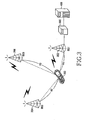
- FIG. 3 illustrates a position measuring system using relative delay information according to the present invention.
- the position measuring system includes a terminal 100, a main base station (BS1) 202, neighboring base stations (BS2 and BS3) 204 and 206, a control station 300, and a Position Determination Entity (PDE) 400.
- BS1 main base station
- BS2 and BS3 neighboring base stations
- PDE Position Determination Entity
- the main base station 202 communicates with the terminal 100 and provides information about the neighboring base stations 204 and 206.
- the terminal 100 determines whether it is necessary to scan the neighboring base stations 204 and 206 in response to a position measurement request. If it is necessary to scan the neighboring base stations 204 and 206, the terminal 100 transmits to the communicating main base station 202 a request for information required to scan the neighboring base stations 204 and 206, receives the information from the main base station 202, and scans the neighboring base stations 204 and 206.
- the information required for the scan includes the time required to scan the neighboring base stations 204 and 206, the number of scan operations, and a scan result reporting mode.
- the terminal 100 After scanning the neighboring base stations 204 and 206, the terminal 100 transmits the scan result to the main base station 202.
- the scan result includes relative delay information indicating a difference between time T 0 required for a downlink signal of the main base station 202 to arrive in the terminal 100 and time T 1 required for a downlink signal from the neighboring base station 204 to arrive in the terminal 100, a difference between time T 0 and time T 2 required for a downlink signal from the neighboring base station 206 to arrive in the terminal 100, and base station ID information.
- the main base station 202 transmits to the control station 300 the scan result from the terminal 100.
- the control station 300 delivers the received scan result to the PDE 400.
- the PDE 400 Upon receipt of the scan result from the control station 300, the PDE 400 extracts the relative delay information and the base station ID information from the received scan result and measures the position of the terminal 100 using the relative delay information and the position information of the base stations 202, 204, and 206 corresponding to the base station ID information.
- the PDE 400 calculates a distance difference of (R1-R2) between the distance R1 between the main base station 202 and the terminal 100 and the distance R2 between the neighboring base station 204 and the terminal 100, and a distance difference of (R1-R3) between the distance R1 and the distance R3 between the neighboring base station 206 and the terminal 100, each using the relative delay information.
- the PDE 400 may calculate the position of the terminal 100 using a trigonometric measurement method with the relative delay information and the position information of the base stations 202, 204, and 206 corresponding to the base station ID information.
- the PDE 400 requires at least two pieces of relative delay information to measure the position of the terminal 100.
- the PDE 400 may calculate the position of the terminal 100 and transmit the calculated position to the terminal 100 as described above, the terminal 100 may measure its position using relative delay information through a position measurement application implemented therein.
- the position measuring system since the position measuring system according to the present invention measures the position of the terminal using relative delay information used in a hand-over, it does not require additional data measurement for positioning and can use a parameter that helps the hand-over for position measurement.
- FIG. 4 is a flowchart illustrating a position measuring method using relative delay information according to a first embodiment of the present invention.
- the terminal 100 requests position measurement and, when a WiBro network is used, a position measurement request from the terminal 100 and a neighboring base station scan result are delivered to the PDE 400 through the main base station (BS1) 202 and the control station 300.
- the main base station (BS1) 202 broadcasts a MOB_NBR_ADV message including information about its neighboring base stations (BS2 and BS3) 204 and 206 in step 402.
- the MOB_NBR_ADV message may be used when a position measurement request is generated by a need to measure the position of the terminal 100 or a need for the main base station 202 to secure a measurement value required for measuring the position of the terminal 100.
- FIG. 9 illustrates the structure of the MOB_NBR_ADV message according to the present invention.
- the MOB_NBR_ADV message includes parameters such as Operator ID, interval (from BS), N_Neighbors, RAS_EIRP, and Neighbor RASID.
- Operator ID is a unique network ID used in a cell in which the terminal 100 is registered.
- Interval is the broadcasting interval of the MOB_NBR_ADV message, i.e., the transmission time interval of the MOB_NRB_ADV message in a Base Station (BS).
- the transmission time interval of the MOB_NRB ADV message in the BS is up to 1 second.
- N_Neighbors composed of 8 bits, is a value combining a Base Station Identification (BSID), a preamble index, and a Downlink Channel Descriptor (DCD) of a neighboring base station.
- BSID Base Station Identification
- DCD Downlink Channel Descriptor
- Remote Access Server (RAS)_EIRP composed of 8 bits, is an Effective Isotropic Radiated Power (EIRP) of a neighboring base station and has an integer value ranging between 128 dBm and +127 dBm.
- EIRP Effective Isotropic Radiated Power
- Neighbor RASID is an RAS ID parameter of least significant 24 bits included in a DL-MAP message for a neighboring base station.
- the Neighbor RASID field is provided only when the first bit of Skip-Optional-Field is 0.
- the MOB_NBR_ADV message includes basic information required for the terminal 100 to scan its neighboring base stations, such as the IDs and number of the neighboring base stations.
- the terminal 100 receives the MOB_NBR_ADV message from the main base station 202 in step 404.
- the terminal 100 can acquire information about its neighboring base stations 204 and 206 from the received MOB_NBR_ADV message.
- the terminal 100 After receipt of the MOB_NBR_ADV message, the terminal 100 determines if a position measurement request is generated in step 406.
- the position measurement request may be generated by a need for the terminal 100 to check its position or a need for the main base station 202 to measure the position of the terminal 100.
- the terminal 100 may transmit a position measurement request message after receipt of the MOB_NBR_ADV message as mentioned above, it may also receive the MOB_NBR_ADV message after transmitting the position measurement request message. In other words, the receipt of the MOB_NBR_ADV message may precede or follow the transmission of the position measurement request message.
- the terminal 100 transmits a position measurement request (MOB_SCN_REQ) message to the main base station 202 in step 408.
- the position measurement request message is an MOB_SCN_REQ message for requesting scanning of the neighboring base stations 204 and 206, and the terminal 100 changes a field value of the MOB_SCN_REQ message to indicate that the MOB_SCN_REQ message is not intended for a hand-over, but is intended for position measurement, and transmits the MOB_SCN_REQ message to the main base station 202.
- the terminal 100 may change code values of a scanning type field into '0b111' to indicate that the MOB_SCN_REQ message is intended for a position measurement.
- FIG. 10 illustrates the structure of the MOB_SCN_REQ message according to the present invention.
- the MOB_SCN_REQ message includes parameters such as Scan duration, Interleaving Interval, Scan Iteration, and Scanning type.
- Scan duration composed of 8 bits, indicates a scan period requested by the terminal 100.
- the scan period may be requested in frame units.
- Interleaving Interval indicates a time interval between actual scan periods, which is required for a general communication process between the terminal 100 and the main base station 202.
- Scan Iteration indicates the number of scan operations performed by the terminal 100.
- code values required for a hand-over are set as indicated by A.
- the code values of Scanning type are changed to those for indicating that the MOB_SCN_REQ message is intended for a position measurement.
- code values of Scanning type are changed in an embodiment of the present invention, code values of any other field that allows the use of reserved code values may be used.
- the main base station 202 transmits the MOB_SCN_REQ message to the control station 300 in step 410.
- the control station 300 transmits the position measurement request message to the PDE 400 in step 412.
- the PDE 400 Upon receipt of the position measurement request message from the terminal 100 through the control station 300, the PDE 400 connects to the terminal 100 through the control station 300 in step 414.
- the PDE 400 transmits a MOB_MSPOS_REQ message transmission command to the control station 300 in step 416.
- the MOB_MSPOS_REQ message transmission command is a command for requesting the main base station 202 to transmit an MOB_SCN_RSP message including information for scanning the neighboring base stations 204 and 206 to the terminal 100.
- the control station 300 receives the MOB_MSPOS_REQ message transmission command and transmits the received MOB_MSPOS_REQ message transmission command to the main base station 202 in step 418.
- the main base station 202 then transmits the MOB_SCN_RSP message to the terminal 100 in step 420.
- the main base station 202 transmits the MOB_SCN_RSP message to the terminal 100 after changing a specific field of the MOB_SCN_RSP message to indicate that the MOB_SCN_RSP message is intended for position measurement.
- the main base station 202 changes the code value of Scanning type of the MOB_SCN_RSP message to '0b111'.
- a reserved code value of another specific field may also be used to indicate that the MOB_SCN_RSP message is intended for position measurement.
- the MOB_SCN_RSP message may be directly transmitted from the main base station 202 to the terminal 100 without a need for the MOB_SCN_RSP transmission command from the PDE 400 or the control station 300.
- the MOB_SCN_RSP message includes information from the MOB_NBR_ADV message, which is required for scanning neighboring base stations, such as time required for a scan operation, the number of scan operations, and a scan result reporting mode.
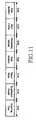
- FIG. 11 illustrates the structure of the MOB_SCN_RSP message according to the present invention.
- the MOB_SCN_RSP message includes parameters such as Scan duration, Start Frame, Interleaving Interval, Scan iteration, Report Mode, Scan Report Period, and Scanning type.
- Scan duration is a parameter indicating a period assigned by the main base station 202 in order for the terminal 100 to scan or associate available neighboring base stations.
- Start Frame composed of 4 bits, is measured from a corresponding frame when the MOB_SCN_RSP message is received.
- Start Frame is set to 0, it means that the first scan period of a next frame begins.
- Interleaving Interval composed of 8 bits, indicates an interval between scan operations when the terminal 100 operates normally.
- Scan iteration composed of 8 bits, indicates the number of intervals between scan operations.
- Report Mode composed of 2 bits, indicates a method for reporting a Carrier to Interference and Noise Ratio (CINR) of a neighboring base station measured during a scan period.
- CINR Carrier to Interference and Noise Ratio
- RAS Remote Access Server
- Report Mode 10
- Report Mode 11 is a reserved mode.
- Scan Report Period composed of 8 bits, indicates a period during which the terminal 100 reports the channel quality measurement result to the main base station 202.
- Scanning type composed of 3 bits, has code values for indicating that the MOB_SCN_RSP message is intended for position measurement.
- the terminal 100 upon receipt of the MOB_SCN_RSP message, the terminal 100 in step 422 scans the neighboring base stations 204 and 206 using the MOB_NBR_ADV message and the MOB_SCN_RSP message and measures relative delay information for the neighboring base stations 204 and 206 according to the scan result.
- the terminal 100 scans the neighboring base stations 204 and 206 by receiving a BS2 base station signal from the neighboring base station 204 and a BS3 base station signal from the neighboring base stations 206 according to the information included in the MOB_SCN_RSP message and measures the relative delay information for the neighboring base stations 204 and 206 according to the scan result.
- the terminal 100 encapsulates the scan result in an MOB_SCN_REPORT message and transmits the MOB_SCN_REPORT message to the main base station 202 in step 424.
- the MOB_SCN_REPORT message includes the relative delay information indicating differences in signal arrival between the terminal 100 and its neighboring base stations 204 and 206.
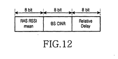
- FIG. 12 illustrates the structure of the MOB_SCN_REPORT message according to the present invention.
- the MOB_SCN_REPORT message includes parameters such as RAS RSSI mean, BS CINR, and Relative Delay.
- RAS RSSI mean composed of 8 bits, indicates a Received Signal Strength Indication of a specific base station.
- RAS RSSI mean is expressed in 0.5dB units and a result of subtracting 40dBm from RAS RSSI mean is the actual signal strength. For example, if RAS RSSI mean is 0xff, it indicates -104dBm and the terminal 100 reports a value ranging between -100dBm and -40dBm.
- RSSI measurement is performed with respect to a preamble and RAS RSSI mean is acquired by averaging measured RSSIs during a specific period.
- BS CINR indicates a CINR received in a terminal from a specific base station.
- CINR indicates a Carrier to Interference and Noise Ratio (CINR) from a base station.
- BS CINR is expressed in 0.5dB units and is interpreted as a byte having a sign.
- CINR measurement is performed with respect to a preamble and BS CINR is acquired by averaging measured CINRs during a specific period.
- Relative Delay composed of 8 bits, indicates a relative delay between downlink signals of the main base station 202 and the neighboring bas stations 204 and 206.
- control station 300 transmits the received MOB_SCN_REPORT message to the PDE 400 in step 428.
- the PDE 400 extracts the relative delay information for the neighboring base stations 204 and 206 and the base station ID information from the MOB_SCN_REPORT message received from the control station 300 in step 430 and measures the position of the terminal 100 using the relative delay information and position information of the base stations 202, 204, and 206 corresponding to the base station ID information in step 432.
- the PDE 400 acquires a difference between a distance between the terminal 100 and the neighboring base station 204, and a distance between the terminal 100 and the neighboring base station 206, using the relative delay information, and measures the position of the terminal 100 using a trigonometric measurement method with the relative delay information and the position information of the base stations 202, 204, and 206.
- the PDE 400 requires at least two pieces of relative delay information to measure the position of the terminal 100.
- the relative delay information includes information indicating the relative delay information of the base stations.
- the PDE 400 may transmit the calculated position to the main base station 202 and/or the terminal 100 to allow the main base station 202 and/or the terminal 100 to know the position of the terminal 100, if necessary.
- the main base station 202 may use the calculated position to be synchronized with the terminal 100 when a hand-over is required for the terminal 100.
- the terminal 100 may transmit the position measurement request using the WiBro network and transmit the neighboring base station scan result directly to the PDE 400 using a TCP/IP network without having to be transmitted via the main base station 202 and the control station 300 as illustrated in FIG. 13 .
- FIG. 13 is a flowchart illustrating a position measuring method using relative delay information according to a sixth embodiment of the present invention.
- the terminal 100 receives the MOB_NBR_ADV message in step S410 and transmits the MOB_SCN_REPORT message including the scan result directly to the PDE 400 in step S426.
- the remaining operations in FIG. 13 are the same as those in FIG. 4 , and will not be further described herein.
- the terminal 100 may directly measure its position using the relative delay information for the neighboring base stations 204 and 206 and position information of the base stations 202, 204, and 206. In other words, the terminal 100 may calculate its position using its measurement value if it determines its position.
- FIG. 5 is a flowchart illustrating a position measuring method using relative delay information according to a second embodiment of the present invention.
- the main base station 202 broadcasts the MOB_NBR_ADV message including information about its neighboring base stations 204 and 206 in step 502.
- the MOB_NBR_ADV message may be used for a position measurement request generated by a need to measure the position of the terminal 100 or a need for the main base station 202 to secure a measurement value required for measuring the position of the terminal 100.
- the terminal 100 receives the MOB_NBR_ADV message from the main base station 202 in step 504.
- the terminal 100 may acquire information about its neighboring base stations 204 and 206 (e.g., the IDs of the neighboring base stations 204 and 206) from the received MOB_NBR_ADV message.
- the terminal 100 After receipt of the MOB_NBR_ADV message, the terminal 100 determines whether a position measurement request is generated in step 506.
- the position measurement request may be generated by a need for the terminal 100 to check its position or a need for the main base station 202 to measure the position of the terminal 100.
- the terminal 100 transmits the MOB_SCN_REQ message for requesting neighboring base station scan information and base station ID information for requesting position information of the base stations 202, 204, and 206 to the PDE 400 through the main base station 202 and the control station 300 in step 508.
- the main base station 202 transmits the MOB_SCN_REQ message and base station ID information received from the terminal 100 to the control station 300.
- the control station 300 transmits the MOB_SCN_REQ message and the base station ID information received from the base station 202 to the PDE 400.
- the main base station 202, the control station 300, and the PDE 400 Upon receipt of the MOB_SCN_REQ message and the base station ID information, the main base station 202, the control station 300, and the PDE 400 recognize that the neighboring base station scan information and position information of the base stations 202, 204, and 206 are requested from the terminal 100.
- the PDE 400 Upon receipt of the MOB_SCN_REQ message and the base station ID information, the PDE 400 transmits in step 510 the MOB_SCN_RSP transmission command and the position information of the base stations 202, 204, and 206 corresponding to the base station ID information to the main bas station 202 through the control station 300. At this time, the PDE 400 also transmits BS Almanac information including the time and position of each base station when transmitting the position information of each of the base stations 202, 204, and 206.
- the main base station 202 Upon receipt of the MOB_SCN_RSP transmission command and the position information of the base stations 202, 204, and 206, the main base station 202 transmits in step 512 the MOB_SCN_RSP message and the position information to the terminal 100.
- the MOB_SCN_RSP message is information for scanning the neighboring base stations 204 and 206 and includes time required for scanning the neighboring base stations 204 and 206, the number of scan operations, and a scan result reporting mode.
- the detailed structure of the MOB_SCN_RSP message has already been described with reference to FIG. 11 .
- the terminal 100 receives the MOB_SCN_RSP message and the position information of the base stations 202, 204, and 206 corresponding to the base station ID information, and scans in step 516 the neighboring base stations 204 and 206 according to the neighboring base station scan information included in the MOB_SCN_RSP message and measures relative delays for the neighboring base stations 204 and 206.
- the terminal 100 receives the BS2 base station signal and the BS3 base station signal according to the neighboring base station scan information, scans the neighboring base stations 204 and 206, and measures the relative delay information for the neighboring base stations 204 and 206 with respect to the main base station 202.
- the terminal 100 measures its position using the relative delay information and the position information of the base stations 202, 204, and 206 corresponding to the base station ID information in step 518. In other words, the terminal 100 acquires a difference between a distance between the terminal 100 and the neighboring base station 204, and a distance between the terminal 100 and the neighboring base station 206, using the relative delay information, and measures its position using a trigonometric measurement method with the relative delay information and the position information of the base stations 202, 204, and 206.
- the PDE 400 provides the position information of the base stations 202, 204, and 206 only to a specific terminal.
- the main base station 202 may broadcast its position information and position information of the neighboring base stations 204 and 206 to all terminals within a corresponding cell through cell broadcasting.
- FIG. 6 is a flowchart illustrating a position measuring method using relative delay information according to a third embodiment of the present invention.
- the main base station 202 broadcasts the MOB_NBR_ADV message including information about its neighboring base stations 204 and 206 in step 602.
- the terminal 100 then receives the MOB_NBR_ADV message from the main base station 202 in step 604.
- the terminal 100 may acquire information about its neighboring base stations 204 and 206 (e.g., the IDs of the neighboring base stations 204 and 206) from the received MOB_NBR_ADV message.
- the control station 300 knows the IDs of base stations 202, 204, and 206 and provides the IDs to the PDE 400 in step 606.
- the PDE 400 Upon receipt of the IDs from the control station 300, the PDE 400 transmits in step 608 position information of the base stations 202, 204, and 206 corresponding to the IDs to the main base station 202.
- the main base station 202 receives the position information of the base stations 202, 204, and 206 corresponding to the IDs from the PDE 400 and broadcasts the received position information to a corresponding cell in step 610.
- the terminal 100 receives the position information in step 612.
- the terminal 100 Upon receipt of the position information, the terminal 100 determines whether the position measurement request is generated in step 614.
- the position measurement request is generated by a need for the terminal 100 to check its position or a need for the main base station 202 to measure the position of the terminal 100.
- the terminal 100 transmits the MOB_SCN_REQ message for requesting neighboring base station scan information to the main base station 202 in step 616.
- the detailed structure of the MOB_SCN_REQ message is already described with reference to FIG. 10 .
- the main base station 202 Upon receipt of the MOB_SCN_REQ message, the main base station 202 transmits the MOB_SCN_RSP message to the terminal 100 in step 618.
- the MOB_SCN_RSP message is information for scanning the neighboring base stations 204 and 206 and includes time required for scanning the neighboring base stations 204 and 206, the number of scan operations, and a scan result reporting mode.
- the detailed structure of the MOB_SCN_RSP message is already described with reference to FIG. 11 .
- the terminal 100 Upon receipt of the MOB_SCN_RSP message from the main base station 202, the terminal 100 scans the neighboring base stations 204 and 206 according to the neighboring base station scan information included in the MOB_SCN_RSP message and measures relative delays for the neighboring base stations 204 and 206 in step 620. For example, the terminal 100 receives the BS2 base station signal and the BS3 base station signal according to the neighboring base station scan information, scans the neighboring base stations 204 and 206, and measures the relative delay information for the neighboring base stations 204 and 206 with respect to the main base station 202.
- the terminal 100 in step 622 then measures its position using the relative delay information and the position information of the base stations 202, 204, and 206 corresponding to the base station ID information.
- the position of the terminal 100 may be measured according to the position measurement request message transmitted to the terminal 100 and the main base station 202 by the PDE 400 when the PDE 400 needs to measure the position of the terminal 100.
- FIG. 7 is a flowchart illustrating a position measuring method using relative delay information according to a fourth embodiment of the present invention.
- the PDE 400 requests position measurement, and a position measurement request from the PDE 400 is transmitted to the terminal 100 via the control station 300 and the main base station 202 using a WiBro network and a neighboring base station scan result from the terminal 100 is transmitted to the PDE 400 via the control station 300 and the main base station 202 using the WiBro network.
- position measurement for the terminal 100 begins with the transmission of a position measurement request message from the PDE 400.
- the PDE 400 transmits the position measurement request (MOB_MSPOS_REQ) message to the control station 300 in step 706 if a position measurement of the terminal 100 is needed.
- the MOB_MSPOS_REQ message includes information indicating that the position measurement request for the terminal 100 is generated and information for causing the main base station 202 to transmit the MOB_SCN_RSP message to the terminal 100.
- the controls station 300 transmits the MOB_MSPOS_REQ message from the PDE 400 to the main base station 202 in step 708.
- the main base station 202 transmits the received MOB_MSPOS_REQ message to the terminal 100 in step 710 and periodically broadcasts the MOB_NBR ADV message including information about its neighboring base stations 204 and 206 in step 711.
- the receipt of the MOB_NBR_ADV message is passively performed in view of the terminal 100 and may precede the transmission of the MOB_MSPOS_REQ message:
- the MOB_NBR_ADV message may be used when the position measurement request is generated by a need to measure the position of the terminal 100 or a need for the main base station 202 to secure a measurement value required for measuring the position of the terminal 100.
- the main base station 202 transmits the MOB_SCN_RSP message to the terminal 100 in step 712 after changing a specific field value of the MOB_SCN_RSP message to indicate that the MOB_SCN_RSP message is intended for position measurement, as described with reference to FIG. 11 .
- the terminal 100 Upon receipt of the position measurement request message from the main base station 202, the terminal 100 can recognize that the position measurement request message for requesting measurement of its position is generated from the PDE 400 and scan its neighboring base stations 204 and 206 required for the measurement using the MOB_SCN_RSP message transmitted from the main base station 202.
- the terminal 100 Upon receipt of the position measurement request message, the MOB_NBR_ADV message, and the MOB_SCN_RSP message from the main base station 202, the terminal 100 scans in step 714 the neighboring base stations 204 and 206 according to information included in the MOB_NBR_ADV message and the MOB_SCN_RSP message and measures relative delay information for the neighboring base stations 204 and 206 according to the scan result in step 714.
- the terminal 100 scans the neighboring base stations 204 and 206 by receiving the BS2 base station signal from the neighboring base station 204 and the BS3 base station signal from the neighboring base station 206 according to the information included in the MOB_SCN_RSP message and measures the relative delay information for the neighboring base stations 204 and 206 according to the scan result.
- the terminal 100 encapsulates the neighboring base station scan result and the relative delay information in the MOB_SCN_REPORT message and transmits the MOB_SCN_REPORT message to the main base station 202 in step 716.
- the main base station 202 Upon receipt of the MOB_SCN_REPORT message from the terminal 100 in step 716, the main base station 202 transmits in step 718 the received MOB_SCN_REPORT message to the controls station 300.
- the control station 300 receives the MOB_SCN_REPORT message from the main base station 202 and then transmits the received MOB_SCN_REPORT message to the PDE 400 in step 720.
- the PDE 400 receives the MOB_SCN_REPORT message from the control station 300, extracts in step 722 the relative delay information and the base station ID information, and measures in step 724 the position of the terminal 100 using the relative delay information and the position information of the base stations 202, 204, and 206 corresponding to the base station ID information. For example, the PDE 400 acquires a difference between a distance between the terminal 100 and the neighboring base station 204, and a distance between the terminal 100 and the neighboring base station 206, using the relative delay information, and measures the position of the terminal 100 using a trigonometric measurement method with the relative delay information and the position information of the base stations 202, 204, and 206.
- the PDE 400 may transmit the position measurement request to the terminal 100 using the WiBro network and the terminal 100 may transmit the neighboring base station scan result directly to the PDE 400 using a TCP/IP network as illustrated in FIG. 15 .
- the MOB_SCN_REPORT message including the neighboring base station scan result is directly to the PDE 400 from the terminal 100 in step S718.
- FIG. 15 is a flowchart illustrating a position measuring method using relative delay information according to an eighth embodiment of the present invention. Steps S706 through S714 of FIG. 15 are the same as steps 706 through 714 of FIG. 7 and steps 722 and 724 are similar to steps 722 and 724.
- the PDE 400 may transmit the position measurement request to the terminal 100 using a TCP/IP network and the terminal 100 may transmit the neighboring base station scan result to the PDE 400 using a WiBro network via the main base station 202 and the control station 300, as illustrated in FIG. 16 .
- a position measurement request (MOB_POS_INIT) message is transmitted directly to the terminal 100 from the PDE 400 using a TCP/IP network in step S908.
- FIG. 16 is a flowchart illustrating a position measuring method using relative delay information according to a ninth embodiment of the present invention. Steps 911 through 924 of FIG. 16 are the same as steps 711 through 724 of FIG. 7 , respectively, and will not be further described herein.
- the PDE 400 may transmit the position measurement request to the terminal 100 using a TCP/IP network and the terminal 100 may transmit the neighboring base station scan result to the PDE 400 using the TCP/IP network, as illustrated in FIG. 17.
- FIG. 17 is a flowchart illustrating a position measuring method using relative delay information according to a tenth embodiment of the present invention. Steps S908 through S914 of FIG. 17 are the same as steps 908 through 914 of FIG. 16 and steps S918 through S924 of FIG. 17 are the same as steps S718 through S724 of FIG. 15 , respectively.
- the terminal 100 may transmit the position measurement request message to the PDE 400 using Internet Protocol (IP).
- IP Internet Protocol
- FIG. 8 is a flowchart illustrating a position measuring method using relative delay information according to a fifth embodiment of the present invention.
- the terminal 100 request position measurement, and the position measurement request from the terminal 100 is transmitted directly to the PDE 400 using a TCP/IP network and the neighboring base station scan result is transmitted from the terminal 100 to the PDE 400 via the main base station 202 and the control station 300 using a WiBro network.
- the MOB_NBR_ADV message is periodically broadcast by the main base station 202 in step 802.
- the terminal 100 After receipt of the MOB_NBR_ADV message in step 804 and determining in step 806 of the position measurement request has been generated, the terminal 100 transmits the position measurement request message to the PDE 400 using IP in step 808 if it determines that it is necessary to measure its position. Steps 810 through 828 are then performed to measure the position of the terminal 100. Since steps 810 through 828 of FIG. 8 are the same as steps 414 through 432 of FIG. 4 , they will not be further described herein.
- FIG. 14 is a flowchart illustrating a position measuring method using relative delay information according to a seventh embodiment of the present invention.
- the terminal 100 requests position measurement, and both the position measurement request and the neighboring base station result from the terminal 100 are transmitted directly to the PDE 400 using a TCP/IP network.
- a position measurement request (MOB_POS_START) message is transmitted to the PDE 400 in step S804.
- the MOB_NBR_ADV message is received in step S806 and the MOB_SCN_REPORT message is transmitted from the terminal 100 directly to the PDE 400 in step S822.
- the remaining operations in FIG. 14 are the same as those in FIG. 8 and will not be further described herein.
- efficiency in the use of a parameter of a WiBro system can be improved by using a parameter previously used only in a hand-over for position measurement.
Landscapes
- Engineering & Computer Science (AREA)
- Physics & Mathematics (AREA)
- General Physics & Mathematics (AREA)
- Radar, Positioning & Navigation (AREA)
- Remote Sensing (AREA)
- Computer Networks & Wireless Communication (AREA)
- Signal Processing (AREA)
- Mobile Radio Communication Systems (AREA)
- Position Fixing By Use Of Radio Waves (AREA)
- Radar Systems Or Details Thereof (AREA)
- Measurement Of Velocity Or Position Using Acoustic Or Ultrasonic Waves (AREA)
- Near-Field Transmission Systems (AREA)
Abstract
Description
- The present invention generally relates to a Wireless Broadband (WiBro) system, and in particular, to a system and method for measuring the position of a terminal in a WiBro system.
- Generally, when a mobile station moves from a cell of a serving base station (or sector) to a cell of a target base station (or sector), a mobile communication system performs a hand-over (or hand-off) in which a communication path is switched to the cell of the target base station using a specific signal to continue communication.
- For example, in a Code Division Multiple Access (CDMA) system, a range between a base station and a terminal is calculated using a Round Trip Delay (RTD) signal transmitted from the base station to the terminal and a hand-over to a base station that is nearest to the terminal is performed. This method is based on the fact that in a context where all base stations operate with the same absolute time, if it takes time t for a signal from a base station to arrive in a terminal, it also takes time t for the terminal to send a signal to the base station (communication paths for transmission/reception are the same) and thus a signal delay between the terminal and the base station is 2t.
- The RTD is based on the distance between the base station and the terminal. Thus, the RTD can be used for not only a hand-over but also measurement of the position of the terminal. However, to measure the position of the terminal using the RTD, a single base station needs to measure RTDs for at least three terminals, or at least three base stations needs to simultaneously receive a signal from a single terminal.
- Thus, in terminal position measurement using the RTD, a clock error between terminals may occur and a base station needs to then have a new positioning algorithm. As a result, the current CDMA system has difficulty in measuring the position of a terminal using the RTD.
-
US 6,356,763 describes that a mobile communication station in a wireless communication network is used to measure the respective times of arrival of radio signals respectively transmitted by a plurality of radio transmitters in the network. The mobile communication station is provided with real time difference information indicative of differences between a time base used by a radio transmitter serving the mobile communication station and respective time bases used by the other radio transmitters. The mobile communication station determines, in response to the real time difference information and relative to the time base used by the radio transmitter serving the mobile communication station, a plurality of points in time at which the respective radio signals are expected to arrive at the mobile communication station. For each radio signal, the mobile communication station monitors for arrival of the radio signal during a period of time after the point in time at which the radio signal is expected to arrive. -
WO 02/17669 A1 - In a Wireless Broadband (WiBro) system, a hand-over between a base station and a terminal is performed using relative delay information. The relative delay information is used only as a parameter for synchronizing the terminal with a new base station during the hand-over.
- The relative delay information is also based on the distance between the terminal and the base station but is not used for measurement of the position of the terminal. Thus, the relative delay may be used for calculation of the position of the terminal.
- If the relative delay information is used, the position of the terminal would be more easily measured because it is not necessary for a single base station to measure RTDs for at least three terminals, or for at least three base stations to simultaneously receive a signal from a single terminal.
- It is, therefore, the object of the present invention to provide a system and method for measuring the position of a terminal using a hand-over parameter of a WiBro signal.
- This object is solved by the subject matter of the independent claims.
- Preferred embodiments are defined in the dependent claims.
- It is an aspect of the present invention to provide a system and method for measuring the position of a terminal using relative delay information of a WiBro signal.
- According to one aspect of the present invention, there is provided a position measuring system using a WiBro signal. The position measuring system includes a main base station for providing information about neighboring base stations and transmitting a neighboring base station scan result from a terminal, the terminal for receiving the information about the neighboring base stations, scanning the neighboring base stations in response to a position measurement request, and transmitting the neighboring base station scan result, and a Position Determination Entity (PDE) for measuring the position of the terminal using relative delay information between the main base station and the neighboring base stations, which is included in the neighboring base station scan result, and base station position information.
- According to another aspect of the present invention, there is provided a position measuring system using a WiBro signal. The position measuring system includes a PDE for providing base station position information, a main base station for providing information about neighboring base stations, and a terminal for scanning the neighboring base stations in response to a position measurement request, measuring relative delay information between the main base station and the neighboring base stations, and measuring its position using the relative delay information and the base station position information provided from the PDE.
- According to further another aspect of the present invention, there is provided a position measuring method using a WiBro signal. The position measuring method includes a main base station providing to a terminal information about neighboring base stations, the terminal scanning the neighboring base stations and transmitting a neighboring base station scan result to a PDE, and a PDE measuring the position of the terminal using relative delay information between the main base station and the neighboring base stations, which is included in the neighboring base station scan result, and previously stored base station position information.
- According to still another aspect of the present invention, there is provided a position measuring method using a WiBro signal. The position measuring method includes a main base station providing to a terminal information about neighboring base stations, the terminal scanning the neighboring base stations and transmitting a neighboring base station scan result to a PDE, and a PDE measuring the position of the terminal using relative delay information between the main base station and the neighboring base stations, which is included in the neighboring base station scan result, and previously stored base station position information.
- The above and other objects, features and advantages of the present invention will become more apparent from the following detailed description when taken in conjunction with the accompanying drawings in which:
-
FIG. 1 illustrates a MOB_SCN_REPORT message in a WiBro system; -
FIG. 2 is a diagram used to illustrate relative delay information according to the present invention; -
FIG. 3 illustrates a position measuring system using relative delay information according to the present invention; -
FIG. 4 is a flowchart illustrating a position measuring method using relative delay information according to a first embodiment of the present invention; -
FIG. 5 is a flowchart illustrating a position measuring method using relative delay information according to a second embodiment of the present invention; -
FIG. 6 is a flowchart illustrating a position measuring method using relative delay information according to a third embodiment of the present invention; -
FIG. 7 is a flowchart illustrating a position measuring method using relative delay information according to a fourth embodiment of the present invention; -
FIG. 8 is a flowchart illustrating a position measuring method using relative delay information according to a fifth embodiment of the present invention; -
FIG. 9 illustrates the structure of a MOB_NBR_ADV message according to the present invention; -
FIG. 10 illustrates the structure of a MOB_SCN_REQ message according to the present invention; -
FIG. 11 illustrates the structure of a MOB_SCN_RSP message according to the present invention; -
FIG. 12 illustrates the structure of a MOB_SCN_REPORT message according to the present invention; -
FIG. 13 is a flowchart illustrating a position measuring method using relative delay information according to a sixth embodiment of the present invention; -
FIG. 14 is a flowchart illustrating a position measuring method using relative delay information according to a seventh embodiment of the present invention; -
FIG. 15 is a flowchart illustrating a position measuring method using relative delay information according to an eighth embodiment of the present invention; -
FIG. 16 is a flowchart illustrating a position measuring method using relative delay information according to a ninth embodiment of the present invention; and -
FIG. 17 is a flowchart illustrating a position measuring method using relative delay information according to a tenth embodiment of the present invention. - Preferred embodiments of the present invention will now be described in detail with reference to the annexed drawings. In the following description, a detailed description of known functions and configurations incorporated herein has been omitted for conciseness.
- A position measuring system according to the present invention measures the position of a terminal using relative delay information that is a hand-over parameter of a WiBro signal.
- In a WiBro system, in a hand-over, a terminal receives neighboring base station information from a main base station, scans its neighboring base stations if it is determined that it is necessary to do so, and transmits the scan result to the main base station through a MOB_SCN_REPORT message that includes the scan result.
-
FIG. 1 illustrates the MOB_SCN_REPORT message in the WiBro system. Referring toFIG. 1 , the MOB_SCN_REPORT message includes parameters such as Neighbor BS ID, BS CINR mean, BS RSSI mean, and Relative Delay as part of the scan result. Theses parameters are used during a hand-over. - In particular,
Relative Delay 10 indicates the relative delay of a downlink signal transmitted from a neighboring base station of a terminal with respect to a downlink signal transmitted from a main base station. In other words, theRelative Delay 10 implies a difference between the time required for the downlink signal of the main base station to arrive in the terminal and the time required for the downlink signal from the neighboring base station to arrive in the terminal. -
FIG. 2 is a diagram used to illustrate relative delay information according to the present invention. - Referring to
FIG. 2 , aterminal 100 receives downlink signals from amain base station 201 and a neighboringbase station 203. Since a distance r1 between theterminal 100 and themain base station 201 and a distance r2 between theterminal 100 and the neighboringbase station 203 are different from each other, the two downlink signals received by theterminal 100 has a signal delay difference corresponding to a distance difference of (r2-r1). Information about the signal delay difference between themain base station 201 and the neighboringbase station 203 is the relative delay information. - Thus, the distance difference (r2-r1) can be acquired using the relative delay information.
- Therefore, a position measuring system according to the present invention calculates the distance difference, i.e., a difference between a distance between a main base station and a terminal and a distance between a neighboring base station and the terminal, using the relative delay information and measures the position of the terminal using the calculated distance difference.
-
FIG. 3 illustrates a position measuring system using relative delay information according to the present invention. Referring toFIG. 3 , the position measuring system includes a terminal 100, a main base station (BS1) 202, neighboring base stations (BS2 and BS3) 204 and 206, acontrol station 300, and a Position Determination Entity (PDE) 400. - The
main base station 202 communicates with the terminal 100 and provides information about the neighboringbase stations base stations base stations base stations main base station 202, and scans the neighboringbase stations base stations - After scanning the neighboring
base stations main base station 202. The scan result includes relative delay information indicating a difference between time T0 required for a downlink signal of themain base station 202 to arrive in the terminal 100 and time T1 required for a downlink signal from the neighboringbase station 204 to arrive in the terminal 100, a difference between time T0 and time T2 required for a downlink signal from the neighboringbase station 206 to arrive in the terminal 100, and base station ID information. - The
main base station 202 transmits to thecontrol station 300 the scan result from the terminal 100. - The
control station 300 delivers the received scan result to thePDE 400. - Upon receipt of the scan result from the
control station 300, thePDE 400 extracts the relative delay information and the base station ID information from the received scan result and measures the position of the terminal 100 using the relative delay information and the position information of thebase stations - Referring to
FIG. 3 , thePDE 400 calculates a distance difference of (R1-R2) between the distance R1 between themain base station 202 and the terminal 100 and the distance R2 between the neighboringbase station 204 and the terminal 100, and a distance difference of (R1-R3) between the distance R1 and the distance R3 between the neighboringbase station 206 and the terminal 100, each using the relative delay information. ThePDE 400 may calculate the position of the terminal 100 using a trigonometric measurement method with the relative delay information and the position information of thebase stations PDE 400 requires at least two pieces of relative delay information to measure the position of the terminal 100. Although thePDE 400 may calculate the position of the terminal 100 and transmit the calculated position to the terminal 100 as described above, the terminal 100 may measure its position using relative delay information through a position measurement application implemented therein. - As mentioned above, since the position measuring system according to the present invention measures the position of the terminal using relative delay information used in a hand-over, it does not require additional data measurement for positioning and can use a parameter that helps the hand-over for position measurement.
-
FIG. 4 is a flowchart illustrating a position measuring method using relative delay information according to a first embodiment of the present invention. InFIG. 4 , the terminal 100 requests position measurement and, when a WiBro network is used, a position measurement request from the terminal 100 and a neighboring base station scan result are delivered to thePDE 400 through the main base station (BS1) 202 and thecontrol station 300. The main base station (BS1) 202 broadcasts a MOB_NBR_ADV message including information about its neighboring base stations (BS2 and BS3) 204 and 206 in step 402. The MOB_NBR_ADV message may be used when a position measurement request is generated by a need to measure the position of the terminal 100 or a need for themain base station 202 to secure a measurement value required for measuring the position of the terminal 100. -
FIG. 9 illustrates the structure of the MOB_NBR_ADV message according to the present invention. Referring toFIG. 9 , the MOB_NBR_ADV message includes parameters such as Operator ID, interval (from BS), N_Neighbors, RAS_EIRP, and Neighbor RASID. - Operator ID is a unique network ID used in a cell in which the terminal 100 is registered.
- Interval (from BS) is the broadcasting interval of the MOB_NBR_ADV message, i.e., the transmission time interval of the MOB_NRB_ADV message in a Base Station (BS). The transmission time interval of the MOB_NRB ADV message in the BS is up to 1 second.
- N_Neighbors, composed of 8 bits, is a value combining a Base Station Identification (BSID), a preamble index, and a Downlink Channel Descriptor (DCD) of a neighboring base station.
- Remote Access Server (RAS)_EIRP, composed of 8 bits, is an Effective Isotropic Radiated Power (EIRP) of a neighboring base station and has an integer value ranging between 128 dBm and +127 dBm. When a BS EIRP indicator bit is set to 0 in PHY Profile ID, the EIRP of a neighboring base station is the same as the EIRP of a main base station.
- Neighbor RASID is an RAS ID parameter of least significant 24 bits included in a DL-MAP message for a neighboring base station. The Neighbor RASID field is provided only when the first bit of Skip-Optional-Field is 0.
- As illustrated in
FIG. 9 , the MOB_NBR_ADV message includes basic information required for the terminal 100 to scan its neighboring base stations, such as the IDs and number of the neighboring base stations. - Returning again to
FIG. 4 , the terminal 100 receives the MOB_NBR_ADV message from themain base station 202 instep 404. The terminal 100 can acquire information about its neighboringbase stations - After receipt of the MOB_NBR_ADV message, the terminal 100 determines if a position measurement request is generated in
step 406. The position measurement request may be generated by a need for the terminal 100 to check its position or a need for themain base station 202 to measure the position of the terminal 100. Although the terminal 100 may transmit a position measurement request message after receipt of the MOB_NBR_ADV message as mentioned above, it may also receive the MOB_NBR_ADV message after transmitting the position measurement request message. In other words, the receipt of the MOB_NBR_ADV message may precede or follow the transmission of the position measurement request message. - If the position measurement request is generated, the terminal 100 transmits a position measurement request (MOB_SCN_REQ) message to the
main base station 202 instep 408. At this time, the position measurement request message is an MOB_SCN_REQ message for requesting scanning of the neighboringbase stations main base station 202. For example, the terminal 100 may change code values of a scanning type field into '0b111' to indicate that the MOB_SCN_REQ message is intended for a position measurement. -
FIG. 10 illustrates the structure of the MOB_SCN_REQ message according to the present invention. Referring toFIG. 10 , the MOB_SCN_REQ message includes parameters such as Scan duration, Interleaving Interval, Scan Iteration, and Scanning type. - Scan duration, composed of 8 bits, indicates a scan period requested by the
terminal 100. The scan period may be requested in frame units. - Interleaving Interval indicates a time interval between actual scan periods, which is required for a general communication process between the terminal 100 and the
main base station 202. - Scan Iteration indicates the number of scan operations performed by the
terminal 100. - In Scanning type, code values required for a hand-over are set as indicated by A. In an embodiment of the present invention, using reserved code values, the code values of Scanning type are changed to those for indicating that the MOB_SCN_REQ message is intended for a position measurement. Although the code values of Scanning type are changed in an embodiment of the present invention, code values of any other field that allows the use of reserved code values may be used.
- Returning again to
FIG. 4 , themain base station 202 transmits the MOB_SCN_REQ message to thecontrol station 300 instep 410. Thecontrol station 300 transmits the position measurement request message to thePDE 400 instep 412. - Upon receipt of the position measurement request message from the terminal 100 through the
control station 300, thePDE 400 connects to the terminal 100 through thecontrol station 300 instep 414. - The
PDE 400 transmits a MOB_MSPOS_REQ message transmission command to thecontrol station 300 instep 416. The MOB_MSPOS_REQ message transmission command is a command for requesting themain base station 202 to transmit an MOB_SCN_RSP message including information for scanning the neighboringbase stations - The
control station 300 receives the MOB_MSPOS_REQ message transmission command and transmits the received MOB_MSPOS_REQ message transmission command to themain base station 202 instep 418. - The
main base station 202 then transmits the MOB_SCN_RSP message to the terminal 100 instep 420. Themain base station 202 transmits the MOB_SCN_RSP message to the terminal 100 after changing a specific field of the MOB_SCN_RSP message to indicate that the MOB_SCN_RSP message is intended for position measurement. For example, themain base station 202 changes the code value of Scanning type of the MOB_SCN_RSP message to '0b111'. A reserved code value of another specific field may also be used to indicate that the MOB_SCN_RSP message is intended for position measurement. - The MOB_SCN_RSP message may be directly transmitted from the
main base station 202 to the terminal 100 without a need for the MOB_SCN_RSP transmission command from thePDE 400 or thecontrol station 300. - The MOB_SCN_RSP message includes information from the MOB_NBR_ADV message, which is required for scanning neighboring base stations, such as time required for a scan operation, the number of scan operations, and a scan result reporting mode.
FIG. 11 illustrates the structure of the MOB_SCN_RSP message according to the present invention. Referring toFIG. 11 , the MOB_SCN_RSP message includes parameters such as Scan duration, Start Frame, Interleaving Interval, Scan iteration, Report Mode, Scan Report Period, and Scanning type. - Scan duration, composed of 8 bits, is a parameter indicating a period assigned by the
main base station 202 in order for the terminal 100 to scan or associate available neighboring base stations. - Start Frame, composed of 4 bits, is measured from a corresponding frame when the MOB_SCN_RSP message is received. When Start Frame is set to 0, it means that the first scan period of a next frame begins.
- Interleaving Interval, composed of 8 bits, indicates an interval between scan operations when the terminal 100 operates normally.
- Scan iteration, composed of 8 bits, indicates the number of intervals between scan operations.
- Report Mode, composed of 2 bits, indicates a method for reporting a Carrier to Interference and Noise Ratio (CINR) of a neighboring base station measured during a scan period. When Report Mode is 00, it indicates a mode where the terminal 100 merely measures the channel quality of a neighboring Remote Access Server (RAS) without reporting. When Report Mode is 01, it indicates a mode where the terminal 100 reports a channel quality measurement result to the
main base station 202 during a scan report period. When Report Mode is 10, it indicates a mode where the terminal 100 reports the channel quality measurement result to themain base station 202 at every channel quality measurement. Report Mode 11 is a reserved mode. - Scan Report Period, composed of 8 bits, indicates a period during which the terminal 100 reports the channel quality measurement result to the
main base station 202. - Scanning type, composed of 3 bits, has code values for indicating that the MOB_SCN_RSP message is intended for position measurement.
- Returning again to
FIG. 4 , upon receipt of the MOB_SCN_RSP message, the terminal 100 instep 422 scans the neighboringbase stations base stations base stations base station 204 and a BS3 base station signal from the neighboringbase stations 206 according to the information included in the MOB_SCN_RSP message and measures the relative delay information for the neighboringbase stations - The terminal 100 encapsulates the scan result in an MOB_SCN_REPORT message and transmits the MOB_SCN_REPORT message to the
main base station 202 instep 424. The MOB_SCN_REPORT message includes the relative delay information indicating differences in signal arrival between the terminal 100 and its neighboringbase stations -
FIG. 12 illustrates the structure of the MOB_SCN_REPORT message according to the present invention. Referring toFIG. 12 , the MOB_SCN_REPORT message includes parameters such as RAS RSSI mean, BS CINR, and Relative Delay. - RAS RSSI mean, composed of 8 bits, indicates a Received Signal Strength Indication of a specific base station. RAS RSSI mean is expressed in 0.5dB units and a result of subtracting 40dBm from RAS RSSI mean is the actual signal strength. For example, if RAS RSSI mean is 0xff, it indicates -104dBm and the terminal 100 reports a value ranging between -100dBm and -40dBm. RSSI measurement is performed with respect to a preamble and RAS RSSI mean is acquired by averaging measured RSSIs during a specific period.
- BS CINR indicates a CINR received in a terminal from a specific base station. CINR indicates a Carrier to Interference and Noise Ratio (CINR) from a base station. BS CINR is expressed in 0.5dB units and is interpreted as a byte having a sign. CINR measurement is performed with respect to a preamble and BS CINR is acquired by averaging measured CINRs during a specific period.
- Relative Delay, composed of 8 bits, indicates a relative delay between downlink signals of the
main base station 202 and the neighboringbas stations - Returning again to
FIG. 4 , thecontrol station 300 transmits the received MOB_SCN_REPORT message to thePDE 400 instep 428. - The
PDE 400 extracts the relative delay information for the neighboringbase stations control station 300 in step 430 and measures the position of the terminal 100 using the relative delay information and position information of thebase stations step 432. In other words, thePDE 400 acquires a difference between a distance between the terminal 100 and the neighboringbase station 204, and a distance between the terminal 100 and the neighboringbase station 206, using the relative delay information, and measures the position of the terminal 100 using a trigonometric measurement method with the relative delay information and the position information of thebase stations PDE 400 requires at least two pieces of relative delay information to measure the position of the terminal 100. The relative delay information includes information indicating the relative delay information of the base stations. - After calculating the position of the terminal 100, the
PDE 400 may transmit the calculated position to themain base station 202 and/or the terminal 100 to allow themain base station 202 and/or the terminal 100 to know the position of the terminal 100, if necessary. Themain base station 202 may use the calculated position to be synchronized with the terminal 100 when a hand-over is required for the terminal 100. - Although the terminal 100 transmits both the position measurement request and the neighboring base station scan result to the
PDE 400 using a WiBro network shown inFIG. 4 , the terminal 100 may transmit the position measurement request using the WiBro network and transmit the neighboring base station scan result directly to thePDE 400 using a TCP/IP network without having to be transmitted via themain base station 202 and thecontrol station 300 as illustrated inFIG. 13 . -
FIG. 13 is a flowchart illustrating a position measuring method using relative delay information according to a sixth embodiment of the present invention. - In
FIG. 13 , after the position measurement request is generated in steps S402 through S408, the terminal 100 receives the MOB_NBR_ADV message in step S410 and transmits the MOB_SCN_REPORT message including the scan result directly to thePDE 400 in step S426. The remaining operations inFIG. 13 are the same as those inFIG. 4 , and will not be further described herein. - According to another embodiment of the present invention, the terminal 100 may directly measure its position using the relative delay information for the neighboring
base stations base stations -
FIG. 5 is a flowchart illustrating a position measuring method using relative delay information according to a second embodiment of the present invention. Referring toFIG. 5 , themain base station 202 broadcasts the MOB_NBR_ADV message including information about its neighboringbase stations step 502. At this time, the MOB_NBR_ADV message may be used for a position measurement request generated by a need to measure the position of the terminal 100 or a need for themain base station 202 to secure a measurement value required for measuring the position of the terminal 100. - The terminal 100 receives the MOB_NBR_ADV message from the
main base station 202 instep 504. The terminal 100 may acquire information about its neighboringbase stations 204 and 206 (e.g., the IDs of the neighboringbase stations 204 and 206) from the received MOB_NBR_ADV message. - After receipt of the MOB_NBR_ADV message, the terminal 100 determines whether a position measurement request is generated in
step 506. The position measurement request may be generated by a need for the terminal 100 to check its position or a need for themain base station 202 to measure the position of the terminal 100. - If the position measurement request is generated, the terminal 100 transmits the MOB_SCN_REQ message for requesting neighboring base station scan information and base station ID information for requesting position information of the
base stations PDE 400 through themain base station 202 and thecontrol station 300 instep 508. At this time, themain base station 202 transmits the MOB_SCN_REQ message and base station ID information received from the terminal 100 to thecontrol station 300. Thecontrol station 300 transmits the MOB_SCN_REQ message and the base station ID information received from thebase station 202 to thePDE 400. Upon receipt of the MOB_SCN_REQ message and the base station ID information, themain base station 202, thecontrol station 300, and thePDE 400 recognize that the neighboring base station scan information and position information of thebase stations - Upon receipt of the MOB_SCN_REQ message and the base station ID information, the
PDE 400 transmits in step 510 the MOB_SCN_RSP transmission command and the position information of thebase stations main bas station 202 through thecontrol station 300. At this time, thePDE 400 also transmits BS Almanac information including the time and position of each base station when transmitting the position information of each of thebase stations - Upon receipt of the MOB_SCN_RSP transmission command and the position information of the
base stations main base station 202 transmits instep 512 the MOB_SCN_RSP message and the position information to the terminal 100. At this time, the MOB_SCN_RSP message is information for scanning the neighboringbase stations base stations FIG. 11 . - The terminal 100 receives the MOB_SCN_RSP message and the position information of the
base stations step 516 the neighboringbase stations base stations - For example, the terminal 100 receives the BS2 base station signal and the BS3 base station signal according to the neighboring base station scan information, scans the neighboring
base stations base stations main base station 202. - The terminal 100 measures its position using the relative delay information and the position information of the
base stations step 518. In other words, the terminal 100 acquires a difference between a distance between the terminal 100 and the neighboringbase station 204, and a distance between the terminal 100 and the neighboringbase station 206, using the relative delay information, and measures its position using a trigonometric measurement method with the relative delay information and the position information of thebase stations - In the previous embodiment of the present invention, the
PDE 400 provides the position information of thebase stations - However, according to yet another embodiment of the present invention, the
main base station 202 may broadcast its position information and position information of the neighboringbase stations -
FIG. 6 is a flowchart illustrating a position measuring method using relative delay information according to a third embodiment of the present invention. Referring toFIG. 6 , themain base station 202 broadcasts the MOB_NBR_ADV message including information about its neighboringbase stations - The terminal 100 then receives the MOB_NBR_ADV message from the
main base station 202 instep 604. The terminal 100 may acquire information about its neighboringbase stations 204 and 206 (e.g., the IDs of the neighboringbase stations 204 and 206) from the received MOB_NBR_ADV message. - The
control station 300 knows the IDs ofbase stations PDE 400 instep 606. - Upon receipt of the IDs from the
control station 300, thePDE 400 transmits instep 608 position information of thebase stations main base station 202. - The
main base station 202 receives the position information of thebase stations PDE 400 and broadcasts the received position information to a corresponding cell instep 610. - The terminal 100 receives the position information in
step 612. - Upon receipt of the position information, the terminal 100 determines whether the position measurement request is generated in
step 614. The position measurement request is generated by a need for the terminal 100 to check its position or a need for themain base station 202 to measure the position of the terminal 100. - If the position measurement request is generated, the terminal 100 transmits the MOB_SCN_REQ message for requesting neighboring base station scan information to the
main base station 202 in step 616. The detailed structure of the MOB_SCN_REQ message is already described with reference toFIG. 10 . - Upon receipt of the MOB_SCN_REQ message, the
main base station 202 transmits the MOB_SCN_RSP message to the terminal 100 in step 618. At this time, the MOB_SCN_RSP message is information for scanning the neighboringbase stations base stations FIG. 11 . - Upon receipt of the MOB_SCN_RSP message from the
main base station 202, the terminal 100 scans the neighboringbase stations base stations step 620. For example, the terminal 100 receives the BS2 base station signal and the BS3 base station signal according to the neighboring base station scan information, scans the neighboringbase stations base stations main base station 202. - The terminal 100 in
step 622 then measures its position using the relative delay information and the position information of thebase stations - According to still another embodiment of the present invention, the position of the terminal 100 may be measured according to the position measurement request message transmitted to the terminal 100 and the
main base station 202 by thePDE 400 when thePDE 400 needs to measure the position of the terminal 100. -
FIG. 7 is a flowchart illustrating a position measuring method using relative delay information according to a fourth embodiment of the present invention. InFIG. 7 , thePDE 400 requests position measurement, and a position measurement request from thePDE 400 is transmitted to the terminal 100 via thecontrol station 300 and themain base station 202 using a WiBro network and a neighboring base station scan result from the terminal 100 is transmitted to thePDE 400 via thecontrol station 300 and themain base station 202 using the WiBro network. - First, position measurement for the terminal 100 begins with the transmission of a position measurement request message from the
PDE 400. To this end, thePDE 400 transmits the position measurement request (MOB_MSPOS_REQ) message to thecontrol station 300 instep 706 if a position measurement of the terminal 100 is needed. At this time, the MOB_MSPOS_REQ message includes information indicating that the position measurement request for the terminal 100 is generated and information for causing themain base station 202 to transmit the MOB_SCN_RSP message to the terminal 100. - The
controls station 300 transmits the MOB_MSPOS_REQ message from thePDE 400 to themain base station 202 instep 708. - The
main base station 202 transmits the received MOB_MSPOS_REQ message to the terminal 100 instep 710 and periodically broadcasts the MOB_NBR ADV message including information about its neighboringbase stations main base station 202 to secure a measurement value required for measuring the position of the terminal 100. Themain base station 202 transmits the MOB_SCN_RSP message to the terminal 100 instep 712 after changing a specific field value of the MOB_SCN_RSP message to indicate that the MOB_SCN_RSP message is intended for position measurement, as described with reference toFIG. 11 . - Upon receipt of the position measurement request message from the
main base station 202, the terminal 100 can recognize that the position measurement request message for requesting measurement of its position is generated from thePDE 400 and scan its neighboringbase stations main base station 202. - Upon receipt of the position measurement request message, the MOB_NBR_ADV message, and the MOB_SCN_RSP message from the
main base station 202, the terminal 100 scans instep 714 the neighboringbase stations base stations step 714. For example, the terminal 100 scans the neighboringbase stations base station 204 and the BS3 base station signal from the neighboringbase station 206 according to the information included in the MOB_SCN_RSP message and measures the relative delay information for the neighboringbase stations - The terminal 100 encapsulates the neighboring base station scan result and the relative delay information in the MOB_SCN_REPORT message and transmits the MOB_SCN_REPORT message to the
main base station 202 in step 716. - Upon receipt of the MOB_SCN_REPORT message from the terminal 100 in step 716, the
main base station 202 transmits instep 718 the received MOB_SCN_REPORT message to thecontrols station 300. - The
control station 300 receives the MOB_SCN_REPORT message from themain base station 202 and then transmits the received MOB_SCN_REPORT message to thePDE 400 instep 720. - The
PDE 400 receives the MOB_SCN_REPORT message from thecontrol station 300, extracts instep 722 the relative delay information and the base station ID information, and measures instep 724 the position of the terminal 100 using the relative delay information and the position information of thebase stations PDE 400 acquires a difference between a distance between the terminal 100 and the neighboringbase station 204, and a distance between the terminal 100 and the neighboringbase station 206, using the relative delay information, and measures the position of the terminal 100 using a trigonometric measurement method with the relative delay information and the position information of thebase stations - Unlike in
FIG. 7 , thePDE 400 may transmit the position measurement request to the terminal 100 using the WiBro network and the terminal 100 may transmit the neighboring base station scan result directly to thePDE 400 using a TCP/IP network as illustrated inFIG. 15 . Referring toFIG. 15 , the MOB_SCN_REPORT message including the neighboring base station scan result is directly to thePDE 400 from the terminal 100 in step S718.FIG. 15 is a flowchart illustrating a position measuring method using relative delay information according to an eighth embodiment of the present invention. Steps S706 through S714 ofFIG. 15 are the same assteps 706 through 714 ofFIG. 7 andsteps steps - Unlike in
FIG. 7 , thePDE 400 may transmit the position measurement request to the terminal 100 using a TCP/IP network and the terminal 100 may transmit the neighboring base station scan result to thePDE 400 using a WiBro network via themain base station 202 and thecontrol station 300, as illustrated inFIG. 16 . Referring toFIG. 16 , a position measurement request (MOB_POS_INIT) message is transmitted directly to the terminal 100 from thePDE 400 using a TCP/IP network in step S908.FIG. 16 is a flowchart illustrating a position measuring method using relative delay information according to a ninth embodiment of the present invention.Steps 911 through 924 ofFIG. 16 are the same as steps 711 through 724 ofFIG. 7 , respectively, and will not be further described herein. - The
PDE 400 may transmit the position measurement request to the terminal 100 using a TCP/IP network and the terminal 100 may transmit the neighboring base station scan result to thePDE 400 using the TCP/IP network, as illustrated inFIG. 17. FIG. 17 is a flowchart illustrating a position measuring method using relative delay information according to a tenth embodiment of the present invention. Steps S908 through S914 ofFIG. 17 are the same assteps 908 through 914 ofFIG. 16 and steps S918 through S924 ofFIG. 17 are the same as steps S718 through S724 ofFIG. 15 , respectively. - According to still another embodiment of the present invention, the terminal 100 may transmit the position measurement request message to the
PDE 400 using Internet Protocol (IP). -
FIG. 8 is a flowchart illustrating a position measuring method using relative delay information according to a fifth embodiment of the present invention. InFIG. 8 , the terminal 100 request position measurement, and the position measurement request from the terminal 100 is transmitted directly to thePDE 400 using a TCP/IP network and the neighboring base station scan result is transmitted from the terminal 100 to thePDE 400 via themain base station 202 and thecontrol station 300 using a WiBro network. - Referring to
FIG. 8 , the MOB_NBR_ADV message is periodically broadcast by themain base station 202 instep 802. After receipt of the MOB_NBR_ADV message instep 804 and determining instep 806 of the position measurement request has been generated, the terminal 100 transmits the position measurement request message to thePDE 400 using IP in step 808 if it determines that it is necessary to measure its position. Steps 810 through 828 are then performed to measure the position of the terminal 100. Since steps 810 through 828 ofFIG. 8 are the same assteps 414 through 432 ofFIG. 4 , they will not be further described herein. -
FIG. 14 is a flowchart illustrating a position measuring method using relative delay information according to a seventh embodiment of the present invention. InFIG. 14 , the terminal 100 requests position measurement, and both the position measurement request and the neighboring base station result from the terminal 100 are transmitted directly to thePDE 400 using a TCP/IP network. Thus, referring toFIG. 14 , if the position measurement request is generated in step S802, a position measurement request (MOB_POS_START) message is transmitted to thePDE 400 in step S804. The MOB_NBR_ADV message is received in step S806 and the MOB_SCN_REPORT message is transmitted from the terminal 100 directly to thePDE 400 in step S822. The remaining operations inFIG. 14 are the same as those inFIG. 8 and will not be further described herein. - As described above, according to the present invention, by using relative delay information of a conventional WiBro system, position measurement can be easily performed.
- Moreover, since the position of a terminal is measured using a parameter used for a hand-over, additional data measurement is not required for the position measurement.
- Furthermore, efficiency in the use of a parameter of a WiBro system can be improved by using a parameter previously used only in a hand-over for position measurement.
- While the present invention has been shown and described with reference to preferred embodiments thereof, it will be understood that the invention is defined by the appended claims.
Claims (23)
- A position measuring system using a wireless broadband signal, comprising:a terminal (100) for transmitting a position measurement request message in response to a position measurement request, scanning neighboring base stations (203; 204, 206), and transmitting a neighboring base station scan result;a main base station (201; 202) for broadcasting information about the neighboring base stations and transmitting a message to the terminal after incorporating in the message information required for scanning the neighboring base stations in response to the position measurement request message; anda position determination entity (400) for receiving the position measurement request message from the terminal and, upon receipt of a neighboring base station scan result, measuring the position of the terminal using the neighboring base station scan result; whereinthe position determination entity measures the position of the terminal using relative delay information (10) between the main base station and the neighboring base stations, which is included in the neighboring base station scan result, and base station position information; andthe relative delay information indicates a difference between the time required for a downlink signal of the main base station to arrive in the terminal and the time required for a downlink signal from the neighboring base station to arrive in the terminal.
- The position measuring system of claim 1, wherein the terminal (100) transmits the position measurement request message and the neighboring base station scan result to the position determination entity (400) using one of the IP address of the position determination entity and a wireless broadband network.
- The position measuring system of claim 2, wherein all messages from the terminal (100) are transmitted directly to the position determination entity (400) when the IP address of the position determination entity is used for the transmission.
- The position measuring system of claim 1, wherein the position measurement request message is a MOB_SCN_REQ message in which a code value of a specific field is changed to indicate that the MOB_NBR_REQ message is intended for position measurement.
- The position measuring system of claim 2, wherein
the main base station (201; 202) broadcasts a MOB_NBR_ADV message that includes the information about the neighboring base stations and transmits a MOB_SCN_RSP message to the terminal after incorporating in the MOB_SCN_RSP message the information that is required for scanning the neighboring base stations; and
the position measuring system further comprises a control station (300) for transmitting and receiving messages between the base station and the position determination entity. - The position measuring system of claim 5, wherein all messages from the terminal (100) are transmitted to the position determination entity (400) via the main base station (201; 202) and the control station (300) when the wireless broadband network is used for the transmission.
- The position measuring system of claim 5, wherein the terminal (100) scans the neighboring base stations (203; 204, 206) using information included in the MOB_NBR_ADV message and the MOB_SCN_RSP message.
- The position measuring system of claim 5, wherein the main base station (201; 202) transmits the MOB_SCN_RSP message after changing a code value of a specific field of the MOB_SCN_RSP message to indicate that the MOB_SCN_RSP message is intended for position measurement.
- A position measuring system using a wireless broadband signal, comprising:a position determination entity (400) for transmitting a position measurement request message in response to a position measurement request;a terminal (100) for scanning neighboring base stations (203; 204, 206) upon receipt of the position measurement request message and transmitting a neighboring base station scan result; anda main base station (202) for broadcasting information about the neighboring base stations and transmitting a message to the terminal after incorporating in the message information required for scanning the neighboring base stations in response to the position measurement request message;wherein upon receipt of the neighboring base station scan result from the terminal, the position determination entity measures the position of the terminal using the neighboring base station scan result, whereinthe position determination entity measures the position of the terminal using relative delay information (10) between the main base station and the neighboring base stations, which is included in the neighboring base station scan result, and base station position information; andthe relative delay information indicates a difference between the time required for a downlink signal of the main base station to arrive in the terminal and the time required for a downlink signal from the neighboring base station to arrive in the terminal.
- The position measuring system of claim 9, wherein the position determination entity (400) transmits the position measurement request message to the terminal (100) using one of the IP address of the terminal and a wireless broadband network.
- The position measuring system of claim 10, wherein the position determination entity (400) transmits the position measurement request message directly to the terminal (100) when the IP address of the terminal is used for the transmission.
- The position measuring system of claim 10, wherein
the main base station (202) is for broadcasting a MOB_NBR_ADV message including the information about the neighboring base stations (203; 204, 205) and transmitting a MOB_SCN_RSP message to the terminal (100) after incorporating in the MOB_SCN_RSP message the information that is required for scanning the neighboring base stations in response to the position measurement request message; and
the position measuring system further comprising a control station (300) for transmitting and receiving messages between the base station and the position determination entity. - The position measuring system of claim 12, wherein the neighboring base station scan result from the terminal (100) is transmitted to the position determination entity (400) via the main base station (202) and the control station (300) when the wireless broadband network is used for the transmission.
- The position measuring system of claim 9, wherein the neighboring base station scan result from the terminal (100) is transmitted directly to the position determination entity (400) when the IP address of the terminal is used for the transmission.
- The position measuring system of claim 12, wherein the position determination entity transmits the position measurement request message to the terminal via the base station and the control station when using the wireless broadband network.
- The position measuring system of claim 12, wherein the main base station (202) transmits the MOB_SCN_RSP message after changing a code value of a specific field of the MOB_SCN_RSP message to indicate that the MOB_SCN_RSP message is intended for position measurement.
- A position measuring method using a wireless broadband signal, comprising the steps of:receiving, by a terminal (100), information about neighboring base stations (203; 204, 206) broadcasted from a main base station (201; 202) and receiving, by the terminal, a response message from said main station (201; 202) including information required for scanning the neighboring base stations in response to the position measurement request message;scanning, by a terminal (100), neighboring base stations in response to a position measurement request and transmitting, by the terminal, a neighboring base station scan result; andreceiving, by a position determination entity (400), the position measurement request message from the terminal and, measuring, by the position determination entity, the position of the terminal using the received neighboring base station scan result; wherein
the position determination entity measures the position of the terminal using relative delay information (10) between the main base station and the neighboring base stations, which is included in the neighboring base station scan result, and base station position information; and
the relative delay information indicates a difference between the time required for a downlink signal of the main base station to arrive in the terminal and the time required for a downlink signal from the neighboring base station to arrive in the terminal. - The position measuring method of claim 17, further comprising:transmitting, by the terminal (100), a position measurement request message to the position determination entity (400) in response to the position measurement request.
- The position measuring method of claim 18, wherein the neighboring base stations (203; 204, 206) are scanned using the broadcasted information and the response message.
- The position measuring method of claim 18, further comprising the step of receiving, by a control base station (300), the neighboring base station scan result, and providing, by the control base station, the received neighboring base station scan result to the position determination entity (400).
- The position measuring method of claim 20, wherein all messages from the terminal (100) are transmitted directly to the position determination entity (400) when an IP address of the position determination entity is used for the transmission.
- The position measuring method of claim 20, wherein all messages from the terminal (400) are transmitted to the position determination entity (400) via the main base station (201; 202) and the control station (300) when a wireless broadband network is used for the transmission.
- The position measuring method of claim 18, wherein the response message is transmitted after a code value of its specific field is changed to indicate that it is intended for position measurement.
Applications Claiming Priority (3)
| Application Number | Priority Date | Filing Date | Title |
|---|---|---|---|
| KR20050059931 | 2005-07-04 | ||
| KR1020060035152A KR100769252B1 (en) | 2005-07-04 | 2006-04-18 | System and method for positioning using portable internet signal |
| EP06012512A EP1742079B1 (en) | 2005-07-04 | 2006-06-19 | Position measuring system and method using wireless broadband (WiBro) signal |
Related Parent Applications (1)
| Application Number | Title | Priority Date | Filing Date |
|---|---|---|---|
| EP06012512A Division EP1742079B1 (en) | 2005-07-04 | 2006-06-19 | Position measuring system and method using wireless broadband (WiBro) signal |
Publications (2)
| Publication Number | Publication Date |
|---|---|
| EP1860455A1 EP1860455A1 (en) | 2007-11-28 |
| EP1860455B1 true EP1860455B1 (en) | 2009-05-27 |
Family
ID=37598128
Family Applications (1)
| Application Number | Title | Priority Date | Filing Date |
|---|---|---|---|
| EP07018112A Not-in-force EP1860455B1 (en) | 2005-07-04 | 2006-06-19 | Position measuring system and method using wireless broadband (WIBRO) signal |
Country Status (8)
| Country | Link |
|---|---|
| EP (1) | EP1860455B1 (en) |
| KR (1) | KR100769252B1 (en) |
| CN (1) | CN1893728A (en) |
| AT (2) | ATE432479T1 (en) |
| BR (1) | BRPI0613556A2 (en) |
| DE (2) | DE602006007267D1 (en) |
| RU (1) | RU2007147633A (en) |
| TW (1) | TW200703978A (en) |
Cited By (4)
| Publication number | Priority date | Publication date | Assignee | Title |
|---|---|---|---|---|
| RU2498344C2 (en) * | 2012-01-11 | 2013-11-10 | Открытое Акционерное Общество "Уральское проектно-конструкторское бюро "Деталь" | Correlation device for measuring height and ground velocity vector components |
| RU2500001C1 (en) * | 2012-03-20 | 2013-11-27 | Открытое Акционерное Общество "Уральское проектно-конструкторское бюро "Деталь" | Pulsed doppler radio altimeter system |
| RU2515524C2 (en) * | 2012-05-28 | 2014-05-10 | Открытое Акционерное Общество "Уральское проектно-конструкторское бюро "Деталь" | Pulse-doppler radar altimetric system |
| RU2522907C2 (en) * | 2012-03-20 | 2014-07-20 | Открытое Акционерное Общество "Уральское проектно-конструкторское бюро "Деталь" | Pulse-doppler radio altimeter |
Families Citing this family (12)
| Publication number | Priority date | Publication date | Assignee | Title |
|---|---|---|---|---|
| US9354321B2 (en) | 2006-03-06 | 2016-05-31 | Qualcomm Incorporated | Method for position determination with measurement stitching |
| EP1931165B1 (en) * | 2006-12-08 | 2010-09-01 | LG - Nortel Co., Ltd. | Method of providing location services in WiMAX network |
| KR100945338B1 (en) | 2006-12-08 | 2010-03-08 | 엘지노텔 주식회사 | Method for providing location services in WiMAX |
| KR100837396B1 (en) * | 2007-01-15 | 2008-06-12 | 삼성에스디아이 주식회사 | Supported catalyst, method for preparing the same, cathode electrode comprising the same, and fuel cell comprising the electrode |
| CN101369902A (en) * | 2007-08-13 | 2009-02-18 | 北京三星通信技术研究有限公司 | Method for implementing positioning service by adopting extended Diameter protocol |
| US9074897B2 (en) | 2009-06-15 | 2015-07-07 | Qualcomm Incorporated | Real-time data with post-processing |
| US8599768B2 (en) * | 2009-08-24 | 2013-12-03 | Intel Corporation | Distributing group size indications to mobile stations |
| US8704707B2 (en) | 2010-06-02 | 2014-04-22 | Qualcomm Incorporated | Position determination using measurements from past and present epochs |
| US10034205B2 (en) * | 2010-10-01 | 2018-07-24 | Telefonaktiebolaget Lm Ericsson (Publ) | Positioning measurements and carrier switching in multi-carrier wireless communication networks |
| US9226260B2 (en) * | 2013-05-10 | 2015-12-29 | Intel Corporation | Initiator-conditioned fine timing measurement service request |
| US9900858B2 (en) | 2013-05-30 | 2018-02-20 | Intel Corporation | Apparatus, system and method of estimating a location of a mobile device |
| KR102212867B1 (en) * | 2018-07-12 | 2021-02-09 | 한양대학교 산학협력단 | Device and method for measuring signal, and server and method for measuring location of terminal |
Family Cites Families (6)
| Publication number | Priority date | Publication date | Assignee | Title |
|---|---|---|---|---|
| US5613205A (en) | 1995-03-31 | 1997-03-18 | Telefonaktiebolaget Lm Ericsson | System and method of locating a mobile terminal within the service area of a cellular telecommunication system |
| US6230018B1 (en) * | 1998-05-14 | 2001-05-08 | Nortel Networks Limited | Devices and processing in a mobile radio communication network having calibration terminals |
| US6490454B1 (en) * | 1998-08-07 | 2002-12-03 | Telefonaktiebolaget Lm Ericsson (Publ) | Downlink observed time difference measurements |
| US6490456B1 (en) * | 1999-10-12 | 2002-12-03 | Lucent Technologies Inc. | Locating a mobile unit in a wireless time division multiple access system |
| FI109839B (en) * | 2000-08-22 | 2002-10-15 | Nokia Corp | A method for locating a mobile station |
| US7123928B2 (en) * | 2003-07-21 | 2006-10-17 | Qualcomm Incorporated | Method and apparatus for creating and using a base station almanac for position determination |
-
2006
- 2006-04-18 KR KR1020060035152A patent/KR100769252B1/en active IP Right Grant
- 2006-06-08 RU RU2007147633/09A patent/RU2007147633A/en not_active Application Discontinuation
- 2006-06-08 BR BRPI0613556-0A patent/BRPI0613556A2/en not_active IP Right Cessation
- 2006-06-14 TW TW095121173A patent/TW200703978A/en unknown
- 2006-06-19 EP EP07018112A patent/EP1860455B1/en not_active Not-in-force
- 2006-06-19 AT AT07018112T patent/ATE432479T1/en not_active IP Right Cessation
- 2006-06-19 AT AT06012512T patent/ATE434194T1/en not_active IP Right Cessation
- 2006-06-19 DE DE602006007267T patent/DE602006007267D1/en active Active
- 2006-06-19 DE DE602006006982T patent/DE602006006982D1/en active Active
- 2006-07-03 CN CNA2006101005262A patent/CN1893728A/en active Pending
Cited By (4)
| Publication number | Priority date | Publication date | Assignee | Title |
|---|---|---|---|---|
| RU2498344C2 (en) * | 2012-01-11 | 2013-11-10 | Открытое Акционерное Общество "Уральское проектно-конструкторское бюро "Деталь" | Correlation device for measuring height and ground velocity vector components |
| RU2500001C1 (en) * | 2012-03-20 | 2013-11-27 | Открытое Акционерное Общество "Уральское проектно-конструкторское бюро "Деталь" | Pulsed doppler radio altimeter system |
| RU2522907C2 (en) * | 2012-03-20 | 2014-07-20 | Открытое Акционерное Общество "Уральское проектно-конструкторское бюро "Деталь" | Pulse-doppler radio altimeter |
| RU2515524C2 (en) * | 2012-05-28 | 2014-05-10 | Открытое Акционерное Общество "Уральское проектно-конструкторское бюро "Деталь" | Pulse-doppler radar altimetric system |
Also Published As
| Publication number | Publication date |
|---|---|
| DE602006006982D1 (en) | 2009-07-09 |
| KR20070004416A (en) | 2007-01-09 |
| TW200703978A (en) | 2007-01-16 |
| KR100769252B1 (en) | 2007-10-23 |
| BRPI0613556A2 (en) | 2011-01-18 |
| ATE432479T1 (en) | 2009-06-15 |
| EP1860455A1 (en) | 2007-11-28 |
| ATE434194T1 (en) | 2009-07-15 |
| DE602006007267D1 (en) | 2009-07-30 |
| CN1893728A (en) | 2007-01-10 |
| RU2007147633A (en) | 2009-06-27 |
Similar Documents
| Publication | Publication Date | Title |
|---|---|---|
| EP1742079B1 (en) | Position measuring system and method using wireless broadband (WiBro) signal | |
| EP1860455B1 (en) | Position measuring system and method using wireless broadband (WIBRO) signal | |
| US10624055B2 (en) | Method for determining location of wireless devices | |
| US9277369B2 (en) | Method for determining location of wireless devices | |
| US7627327B2 (en) | Network overlay location system and method for air interface with frequency hopping | |
| EP2781129B1 (en) | Method and apparatus for determining distance in a wi-fi network | |
| US7546084B2 (en) | System and method of operation for network overlay geolocation system with repeaters | |
| US7274939B2 (en) | Cellular radio locator system | |
| US7280831B2 (en) | Method for identification of base stations and for checking measurement values of an observed time difference between transmissions from base stations | |
| US9288625B2 (en) | Method for determining location of wireless devices based on information within messages received from other network devices | |
| US20090149198A1 (en) | System and method for tracking position | |
| CN102318416B (en) | Method and arrangement for determining terminal position | |
| WO2008039144A1 (en) | Method and arrangement for base station location, base station synchronization and mobile station location | |
| KR20100117634A (en) | Method and apparatus of mobile device location | |
| KR102294832B1 (en) | Method and system for improving the accuracy of positioning method based on 5g new radio network | |
| KR100345027B1 (en) | Method and apparatus for measuring radio-wave | |
| KR102287266B1 (en) | Wireless localization ranging method between devieces using cooperation terminal and system thereof | |
| WO2023212836A1 (en) | Apparatus and method for discovering positioning reference user equipment on sidelink | |
| CN116419390A (en) | Positioning method, positioning network element, system and computer readable recording medium | |
| KR20110085889A (en) | Base station, relay station, and operating method thereof | |
| JP3752515B2 (en) | Method for determining timing differences between a wireless transmitter and a wireless network incorporating it | |
| JP3752515B6 (en) | Method for determining timing differences between a wireless transmitter and a wireless network incorporating it |
Legal Events
| Date | Code | Title | Description |
|---|---|---|---|
| PUAI | Public reference made under article 153(3) epc to a published international application that has entered the european phase |
Free format text: ORIGINAL CODE: 0009012 |
|
| 17P | Request for examination filed |
Effective date: 20070914 |
|
| AC | Divisional application: reference to earlier application |
Ref document number: 1742079 Country of ref document: EP Kind code of ref document: P |
|
| AK | Designated contracting states |
Kind code of ref document: A1 Designated state(s): AT BE BG CH CY CZ DE DK EE ES FI FR GB GR HU IE IS IT LI LT LU LV MC NL PL PT RO SE SI SK TR |
|
| AX | Request for extension of the european patent |
Extension state: AL BA HR MK YU |
|
| 17Q | First examination report despatched |
Effective date: 20080111 |
|
| AKX | Designation fees paid |
Designated state(s): AT BE BG CH CY CZ DE DK EE ES FI FR GB GR HU IE IS IT LI LT LU LV MC NL PL PT RO SE SI SK TR |
|
| GRAP | Despatch of communication of intention to grant a patent |
Free format text: ORIGINAL CODE: EPIDOSNIGR1 |
|
| GRAS | Grant fee paid |
Free format text: ORIGINAL CODE: EPIDOSNIGR3 |
|
| GRAA | (expected) grant |
Free format text: ORIGINAL CODE: 0009210 |
|
| AC | Divisional application: reference to earlier application |
Ref document number: 1742079 Country of ref document: EP Kind code of ref document: P |
|
| AK | Designated contracting states |
Kind code of ref document: B1 Designated state(s): AT BE BG CH CY CZ DE DK EE ES FI FR GB GR HU IE IS IT LI LT LU LV MC NL PL PT RO SE SI SK TR |
|
| REG | Reference to a national code |
Ref country code: GB Ref legal event code: FG4D |
|
| REG | Reference to a national code |
Ref country code: CH Ref legal event code: EP |
|
| REG | Reference to a national code |
Ref country code: IE Ref legal event code: FG4D |
|
| REF | Corresponds to: |
Ref document number: 602006006982 Country of ref document: DE Date of ref document: 20090709 Kind code of ref document: P |
|
| PG25 | Lapsed in a contracting state [announced via postgrant information from national office to epo] |
Ref country code: AT Free format text: LAPSE BECAUSE OF FAILURE TO SUBMIT A TRANSLATION OF THE DESCRIPTION OR TO PAY THE FEE WITHIN THE PRESCRIBED TIME-LIMIT Effective date: 20090527 Ref country code: PT Free format text: LAPSE BECAUSE OF FAILURE TO SUBMIT A TRANSLATION OF THE DESCRIPTION OR TO PAY THE FEE WITHIN THE PRESCRIBED TIME-LIMIT Effective date: 20090927 Ref country code: LT Free format text: LAPSE BECAUSE OF FAILURE TO SUBMIT A TRANSLATION OF THE DESCRIPTION OR TO PAY THE FEE WITHIN THE PRESCRIBED TIME-LIMIT Effective date: 20090527 |
|
| NLV1 | Nl: lapsed or annulled due to failure to fulfill the requirements of art. 29p and 29m of the patents act | ||
| PG25 | Lapsed in a contracting state [announced via postgrant information from national office to epo] |
Ref country code: SI Free format text: LAPSE BECAUSE OF FAILURE TO SUBMIT A TRANSLATION OF THE DESCRIPTION OR TO PAY THE FEE WITHIN THE PRESCRIBED TIME-LIMIT Effective date: 20090527 Ref country code: PL Free format text: LAPSE BECAUSE OF FAILURE TO SUBMIT A TRANSLATION OF THE DESCRIPTION OR TO PAY THE FEE WITHIN THE PRESCRIBED TIME-LIMIT Effective date: 20090527 Ref country code: IS Free format text: LAPSE BECAUSE OF FAILURE TO SUBMIT A TRANSLATION OF THE DESCRIPTION OR TO PAY THE FEE WITHIN THE PRESCRIBED TIME-LIMIT Effective date: 20090927 Ref country code: LV Free format text: LAPSE BECAUSE OF FAILURE TO SUBMIT A TRANSLATION OF THE DESCRIPTION OR TO PAY THE FEE WITHIN THE PRESCRIBED TIME-LIMIT Effective date: 20090527 Ref country code: SE Free format text: LAPSE BECAUSE OF FAILURE TO SUBMIT A TRANSLATION OF THE DESCRIPTION OR TO PAY THE FEE WITHIN THE PRESCRIBED TIME-LIMIT Effective date: 20090827 Ref country code: NL Free format text: LAPSE BECAUSE OF FAILURE TO SUBMIT A TRANSLATION OF THE DESCRIPTION OR TO PAY THE FEE WITHIN THE PRESCRIBED TIME-LIMIT Effective date: 20090527 |
|
| PG25 | Lapsed in a contracting state [announced via postgrant information from national office to epo] |
Ref country code: RO Free format text: LAPSE BECAUSE OF FAILURE TO SUBMIT A TRANSLATION OF THE DESCRIPTION OR TO PAY THE FEE WITHIN THE PRESCRIBED TIME-LIMIT Effective date: 20090527 Ref country code: MC Free format text: LAPSE BECAUSE OF NON-PAYMENT OF DUE FEES Effective date: 20090630 Ref country code: EE Free format text: LAPSE BECAUSE OF FAILURE TO SUBMIT A TRANSLATION OF THE DESCRIPTION OR TO PAY THE FEE WITHIN THE PRESCRIBED TIME-LIMIT Effective date: 20090527 Ref country code: ES Free format text: LAPSE BECAUSE OF FAILURE TO SUBMIT A TRANSLATION OF THE DESCRIPTION OR TO PAY THE FEE WITHIN THE PRESCRIBED TIME-LIMIT Effective date: 20090907 Ref country code: CZ Free format text: LAPSE BECAUSE OF FAILURE TO SUBMIT A TRANSLATION OF THE DESCRIPTION OR TO PAY THE FEE WITHIN THE PRESCRIBED TIME-LIMIT Effective date: 20090527 Ref country code: DK Free format text: LAPSE BECAUSE OF FAILURE TO SUBMIT A TRANSLATION OF THE DESCRIPTION OR TO PAY THE FEE WITHIN THE PRESCRIBED TIME-LIMIT Effective date: 20090527 |
|
| PG25 | Lapsed in a contracting state [announced via postgrant information from national office to epo] |
Ref country code: BE Free format text: LAPSE BECAUSE OF FAILURE TO SUBMIT A TRANSLATION OF THE DESCRIPTION OR TO PAY THE FEE WITHIN THE PRESCRIBED TIME-LIMIT Effective date: 20090527 Ref country code: SK Free format text: LAPSE BECAUSE OF FAILURE TO SUBMIT A TRANSLATION OF THE DESCRIPTION OR TO PAY THE FEE WITHIN THE PRESCRIBED TIME-LIMIT Effective date: 20090527 |
|
| PG25 | Lapsed in a contracting state [announced via postgrant information from national office to epo] |
Ref country code: BG Free format text: LAPSE BECAUSE OF FAILURE TO SUBMIT A TRANSLATION OF THE DESCRIPTION OR TO PAY THE FEE WITHIN THE PRESCRIBED TIME-LIMIT Effective date: 20090827 |
|
| PLBE | No opposition filed within time limit |
Free format text: ORIGINAL CODE: 0009261 |
|
| STAA | Information on the status of an ep patent application or granted ep patent |
Free format text: STATUS: NO OPPOSITION FILED WITHIN TIME LIMIT |
|
| PG25 | Lapsed in a contracting state [announced via postgrant information from national office to epo] |
Ref country code: IE Free format text: LAPSE BECAUSE OF NON-PAYMENT OF DUE FEES Effective date: 20090619 |
|
| 26N | No opposition filed |
Effective date: 20100302 |
|
| REG | Reference to a national code |
Ref country code: FR Ref legal event code: ST Effective date: 20100531 |
|
| PG25 | Lapsed in a contracting state [announced via postgrant information from national office to epo] |
Ref country code: FR Free format text: LAPSE BECAUSE OF NON-PAYMENT OF DUE FEES Effective date: 20090727 |
|
| PG25 | Lapsed in a contracting state [announced via postgrant information from national office to epo] |
Ref country code: GR Free format text: LAPSE BECAUSE OF FAILURE TO SUBMIT A TRANSLATION OF THE DESCRIPTION OR TO PAY THE FEE WITHIN THE PRESCRIBED TIME-LIMIT Effective date: 20090828 |
|
| REG | Reference to a national code |
Ref country code: CH Ref legal event code: PL |
|
| PG25 | Lapsed in a contracting state [announced via postgrant information from national office to epo] |
Ref country code: FI Free format text: LAPSE BECAUSE OF FAILURE TO SUBMIT A TRANSLATION OF THE DESCRIPTION OR TO PAY THE FEE WITHIN THE PRESCRIBED TIME-LIMIT Effective date: 20090527 |
|
| PG25 | Lapsed in a contracting state [announced via postgrant information from national office to epo] |
Ref country code: CH Free format text: LAPSE BECAUSE OF NON-PAYMENT OF DUE FEES Effective date: 20090630 Ref country code: IT Free format text: LAPSE BECAUSE OF FAILURE TO SUBMIT A TRANSLATION OF THE DESCRIPTION OR TO PAY THE FEE WITHIN THE PRESCRIBED TIME-LIMIT Effective date: 20090527 Ref country code: LI Free format text: LAPSE BECAUSE OF NON-PAYMENT OF DUE FEES Effective date: 20090630 |
|
| PG25 | Lapsed in a contracting state [announced via postgrant information from national office to epo] |
Ref country code: CH Free format text: LAPSE BECAUSE OF NON-PAYMENT OF DUE FEES Effective date: 20100630 Ref country code: LU Free format text: LAPSE BECAUSE OF NON-PAYMENT OF DUE FEES Effective date: 20090619 Ref country code: LI Free format text: LAPSE BECAUSE OF NON-PAYMENT OF DUE FEES Effective date: 20100630 |
|
| PG25 | Lapsed in a contracting state [announced via postgrant information from national office to epo] |
Ref country code: HU Free format text: LAPSE BECAUSE OF FAILURE TO SUBMIT A TRANSLATION OF THE DESCRIPTION OR TO PAY THE FEE WITHIN THE PRESCRIBED TIME-LIMIT Effective date: 20091128 |
|
| PG25 | Lapsed in a contracting state [announced via postgrant information from national office to epo] |
Ref country code: TR Free format text: LAPSE BECAUSE OF FAILURE TO SUBMIT A TRANSLATION OF THE DESCRIPTION OR TO PAY THE FEE WITHIN THE PRESCRIBED TIME-LIMIT Effective date: 20090527 |
|
| PG25 | Lapsed in a contracting state [announced via postgrant information from national office to epo] |
Ref country code: CY Free format text: LAPSE BECAUSE OF FAILURE TO SUBMIT A TRANSLATION OF THE DESCRIPTION OR TO PAY THE FEE WITHIN THE PRESCRIBED TIME-LIMIT Effective date: 20090527 |
|
| PGFP | Annual fee paid to national office [announced via postgrant information from national office to epo] |
Ref country code: DE Payment date: 20190520 Year of fee payment: 14 |
|
| PGFP | Annual fee paid to national office [announced via postgrant information from national office to epo] |
Ref country code: GB Payment date: 20190521 Year of fee payment: 14 |
|
| REG | Reference to a national code |
Ref country code: DE Ref legal event code: R119 Ref document number: 602006006982 Country of ref document: DE |
|
| GBPC | Gb: european patent ceased through non-payment of renewal fee |
Effective date: 20200619 |
|
| PG25 | Lapsed in a contracting state [announced via postgrant information from national office to epo] |
Ref country code: GB Free format text: LAPSE BECAUSE OF NON-PAYMENT OF DUE FEES Effective date: 20200619 |
|
| PG25 | Lapsed in a contracting state [announced via postgrant information from national office to epo] |
Ref country code: DE Free format text: LAPSE BECAUSE OF NON-PAYMENT OF DUE FEES Effective date: 20210101 |