EP1860310A2 - Method of operating a fuel injector - Google Patents
Method of operating a fuel injector Download PDFInfo
- Publication number
- EP1860310A2 EP1860310A2 EP07252080A EP07252080A EP1860310A2 EP 1860310 A2 EP1860310 A2 EP 1860310A2 EP 07252080 A EP07252080 A EP 07252080A EP 07252080 A EP07252080 A EP 07252080A EP 1860310 A2 EP1860310 A2 EP 1860310A2
- Authority
- EP
- European Patent Office
- Prior art keywords
- injector
- discharge
- value
- drive pulse
- time period
- Prior art date
- Legal status (The legal status is an assumption and is not a legal conclusion. Google has not performed a legal analysis and makes no representation as to the accuracy of the status listed.)
- Granted
Links
- 239000000446 fuel Substances 0.000 title claims abstract description 57
- 238000000034 method Methods 0.000 title claims abstract description 37
- 238000009434 installation Methods 0.000 claims abstract description 15
- 238000002347 injection Methods 0.000 claims description 49
- 239000007924 injection Substances 0.000 claims description 49
- 230000009467 reduction Effects 0.000 claims description 14
- 238000013500 data storage Methods 0.000 claims description 4
- 238000004590 computer program Methods 0.000 claims description 3
- 238000000926 separation method Methods 0.000 claims description 3
- 238000002485 combustion reaction Methods 0.000 description 11
- 230000008569 process Effects 0.000 description 4
- 230000004913 activation Effects 0.000 description 3
- 238000010586 diagram Methods 0.000 description 3
- 230000000694 effects Effects 0.000 description 3
- 230000003247 decreasing effect Effects 0.000 description 2
- 230000004044 response Effects 0.000 description 2
- 230000003213 activating effect Effects 0.000 description 1
- 230000002411 adverse Effects 0.000 description 1
- 230000009286 beneficial effect Effects 0.000 description 1
- 230000008901 benefit Effects 0.000 description 1
- 230000002457 bidirectional effect Effects 0.000 description 1
- 239000003990 capacitor Substances 0.000 description 1
- 238000007599 discharging Methods 0.000 description 1
- 238000006073 displacement reaction Methods 0.000 description 1
- 230000006870 function Effects 0.000 description 1
- 230000000977 initiatory effect Effects 0.000 description 1
- 239000000203 mixture Substances 0.000 description 1
- 230000004048 modification Effects 0.000 description 1
- 238000012986 modification Methods 0.000 description 1
- 238000001208 nuclear magnetic resonance pulse sequence Methods 0.000 description 1
- 238000001228 spectrum Methods 0.000 description 1
- 230000002123 temporal effect Effects 0.000 description 1
- 230000007704 transition Effects 0.000 description 1
Images





Classifications
-
- F—MECHANICAL ENGINEERING; LIGHTING; HEATING; WEAPONS; BLASTING
- F02—COMBUSTION ENGINES; HOT-GAS OR COMBUSTION-PRODUCT ENGINE PLANTS
- F02D—CONTROLLING COMBUSTION ENGINES
- F02D41/00—Electrical control of supply of combustible mixture or its constituents
- F02D41/20—Output circuits, e.g. for controlling currents in command coils
- F02D41/2096—Output circuits, e.g. for controlling currents in command coils for controlling piezoelectric injectors
Definitions
- the invention relates to a method of operating a fuel injector. More specifically, the invention relates to a method of operating a piezoelectrically actuated fuel injector in order to reduce the level of noise that is generated by the injector.
- a fuel injector is provided to deliver a charge of atomised fuel into a combustion chamber prior to ignition.
- the fuel injector is mounted in a cylinder head of an engine with respect to the combustion chamber such that a tip of the injector protrudes slightly into the chamber to permit the fuel charge to be delivered thereto.
- One type of fuel injector that is particularly suited for use in a direct injection engine is a so-called piezoelectric injector.
- Such an injector allows precise control of the timing of an injection event and of the total volume of fuel that is delivered to the combustion chamber during the injection event. This permits accurate control over the combustion process which is beneficial for fuel efficiency and exhaust emissions.
- a known piezoelectric injector 2 and its associated control system 3 is shown schematically in Figure 1.
- the piezoelectric injector 2 includes a piezoelectric actuator 4 that is operable to control the position of an injector valve needle 6 relative to a valve needle seat 8.
- the piezoelectric actuator 4 includes a stack 7 of piezoelectric elements that expands and contacts in dependence on the voltage across the stack 7.
- the axial position, or 'lift', of the valve needle 6 is controlled by applying a variable voltage 'V' to the piezoelectric actuator 4.
- the variable voltage would be applied to the actuator by connecting a power supply plug to the terminals of the injector.
- valve needle 6 is caused either to disengage the valve seat 8, in which case fuel is delivered into an associated combustion chamber (not shown) through a set of nozzle outlets 10, or is caused to engage the valve seat 8, in which case fuel delivery through the outlets 10 is prevented.
- an injector of this type is described in applicant's European Patent No. EP 0955901 B .
- Such fuel injectors can be used in compression-ignition (diesel) engines or spark ignition (petrol) engines.
- piezoelectric injectors are adept at delivering precise quantities of fuel with accurate timing, they also have associated disadvantages. For example, during use, a piezoelectric injector emits vibrations due to the frequency of the drive voltage that is applied to the piezoelectric actuator. The vibrations travel down the injector, or through an injector positioning/clamping arrangement, and are transmitted to the engine. The engine accentuates certain frequencies such that at least a portion of the vibrations can be detected by the human ear.
- the emitted noise of the injectors is drowned out by the combustion noise of the engine.
- the audible injector noise is apparent.
- the detectable noise contributes to the overall noise/vibration/harshness (NVH) characteristics of the vehicle.
- NVH characteristics are a significant factor in successful vehicle design since it influences the buying decision of the consumer. It is therefore desirable to reduce the amount of noise emitted by the injector in an effort to reduce the overall level of noise perceived by the user of the vehicle.
- the invention provides a method of operating a fuel injector, the injector having a piezoelectric actuator operable by applying a drive pulse thereto, wherein the drive pulse has a frequency domain signature, the method including determining at least one resonant frequency of an injector installation in which the injector is received, in use, and modifying the drive pulse such that a maximum/maxima of the frequency domain signature is remote from or does not coincide with the determined resonant frequency of the injector installation.
- the drive pulse may be defined by a plurality of drive pulse characteristics including a discharge time period, an injector on time period and a peak discharge/charge current amplitude such that the step of modifying the injector drive pulse includes modifying one or more of selected ones of said characteristics.
- the method may include the steps of receiving a value that represents the demanded fuel volume and determining a tuned injector on time value by referring to a first data map relating the value to the tuned injector on time value, and using the determined tuned injector on time value for subsequent operation of the injector.
- the method may include determining a discharge time period value by referring to a second data map relating the value to the discharge time period value, and determining a peak discharge/charge current amplitude value by referring to a third data map relating the value to the peak discharge/charge current amplitude value.
- the determined values of discharge time period and peak discharge/charge current amplitude may be used for subsequent operation of the injector.
- the method in order to reduce the volume of fuel delivered by the injector during a first series of successive injection events, includes reducing the injector on time period to a predetermined injector on time threshold value and, for subsequent reductions in fuel delivery volume, holding the injector on time period substantially constant and thereafter reducing the discharge time period.
- the injector on time period may be held substantially constant, the discharge time period may be held substantially constant, and the peak discharge/charge current amplitude may be reduced to a predetermined peak current threshold value in order to further reduce the volume of fuel that is delivered by the injector over the subsequent series of successive injection events.
- the method in order to reduce the volume of fuel delivered by the injector during a first series of successive injection events, includes reducing the injector on time period to a predetermined injector on time threshold value and, for subsequent reductions in fuel delivery volume, holding the injector on time period substantially constant and thereafter reducing the peak discharge/charge current amplitude to a predetermined peak current threshold value.
- the injector on time period may be held substantially constant
- the peak discharge/charge current amplitude may be held substantially constant
- the discharge time period may be reduced in order to further reduce the volume of fuel that is delivered by the injector.
- an injection comprises a plurality of injector drive pulses, for example in the form of first and second pilot drive pulses and a single main drive pulse
- the temporal separation between successive drive pulses may be selected so as to modify the frequency domain signature of the drive pulse sequence such that a maximum of the frequency domain signature is remote from the determined resonant frequency of the injector installation.
- the invention provides a computer program product comprising at least one computer program software portion which, when executed in an executing environment, is operable to implement the method as set forth above.
- the invention provides a data storage medium having the or each computer program product stored thereon.
- the invention provides a microcomputer provided with the data storage medium thereon.
- Figure 1 is a schematic representation of a known piezoelectric injector 2 and its associated control system, including an injector drive circuit.
- the piezoelectric injector 2 is controlled by an injector control unit 20 (hereinafter 'ICU') that forms an integral part of an engine control unit 22 (ECU).
- the ECU 22 monitors a plurality of engine parameters 24 and calculates an engine power requirement signal (not shown) which is input to the ICU 20.
- the ICU 20 calculates a required injection event sequence to provide the required power for the engine and operates an injector drive circuit 26 accordingly.
- the injector drive circuit 26 is also shown as integral to the ECU 22, although it should be appreciated that this is not essential to the invention.
- the injector drive circuit 26 causes the differential voltage between the high and low voltage terminals of the injector, V 1 and V 2 , to transition from a high voltage (typically 200 V) at which no fuel delivery occurs, to a relatively low voltage (typically -30 V), which reduces the voltage of the piezoelectric actuator 4 and therefore initiates fuel delivery.
- An injector responsive to this drive waveform is referred to as a 'de-energise to inject' injector and is operable to deliver one or more injections of fuel within a single injection event.
- the injection event may include one or more so-called 'pre-' or 'pilot' injections, a main injection, and one or more 'post' injections. In general, several such injections within a single injection event are preferred to increase combustion efficiency of the engine.
- the injector drive circuit 26 includes an injector charge/discharge switching circuit 30 (hereinafter 'switching circuit') that is connected to an injector bank circuit 32 so as to control the voltage applied to a high side voltage input V1 and a low side voltage input V2 of the bank circuit 32.
- an injector charge/discharge switching circuit 30 (hereinafter 'switching circuit') that is connected to an injector bank circuit 32 so as to control the voltage applied to a high side voltage input V1 and a low side voltage input V2 of the bank circuit 32.
- the injector bank circuit 32 includes first and second branches 40, 42 both of which are connected in parallel between the high and low side voltage inputs V1 and V2.
- Each branch 40, 42 includes a respective injector INJ1, INJ2 and injector select switch QS1, QS2 by which means either one of the injectors can be selected for operation, as will be described later.
- the piezoelectric actuator 4 of each injector 2 is considered electrically equivalent to a capacitor, the voltage difference between V1 and V2 determining the amount of electrical charge stored by the actuator and, thus, the position of the injector valve needle 8.
- the switching circuit 30 includes three input voltage rails: a high voltage rail V HI (typically 230 V), a mid voltage rail V MID (typically 30 V) and a ground connection GND.
- the switching circuit 30 is operable to connect the high side voltage input V1 of the injector bank circuit to either the high voltage rail V HI or the ground connection GND by means of first and second switches Q1, Q2 to which the injector bank 32 is connected, through an inductor L.
- the switching circuit 30 is also provided with a diode D1 that connects the high side voltage input V1 of the bank circuit 32 to the high voltage rail V HI .
- the diode D1 is oriented to permit current to flow from the high side input V1 of the bank circuit 32 to the high voltage rail V HI but to prevent current flow from the high voltage rail V HI to the high side voltage input V1 of the bank circuit 32.
- the first switch Q1 when activated, connects the high side input V1 of the selected injector to the ground connection GND via the inductor L. Therefore, charge from the injector is permitted to flow from the selected injector, through the inductor L and the first switch Q1 to the ground connection GND, thereby serving to discharge the selected injector during an injector discharge phase.
- the first switch will therefore be referred to as the 'discharge select switch' Q1.
- a diode D Q1 is connected across the second switch Q2 and is oriented to permit current to flow from the inductor L to the high voltage rail V HI when the discharge select switch Q1 is deactivated, thus guarding against voltage peaks across the inductor L.
- the second switch Q2 when activated, connects the high side input V1 of the selected injector to the high voltage rail V HI via the inductor L.
- activating the second switch Q2 causes charge to flow from the high voltage rail V HI , through the second switch Q2 and the inductor L, and into the injector, during an injector charge phase, until an equilibrium voltage is reached (the point at which the voltage due to charge stored by the actuator equals the voltage difference between the high side and low side voltage inputs V1, V2).
- the second switch will be referred to as the 'charge select switch' Q2.
- a diode D Q2 is connected across the discharge select switch Q1 and is oriented to permit current to flow from the ground connection GND through the inductor L to the high side input V1 when the charge select switch Q2 is deactivated, thus guarding against voltage peaks across the inductor L.
- the inductor L constitutes a bidirectional current path since current flows in a first direction through the inductor L during the discharge phase and in a second, opposite direction during the injector charge phase.
- the low side voltage input V2 of the injector bank circuit 32 is connected to the mid voltage rail V MID via a voltage sense resistor 44.
- a current sensing and comparator means 50 (hereinafter 'comparator module') is connected in parallel with the sense resistor 44 and is operable to monitor the current flowing therethrough.
- the comparator module 50 outputs a control signal 52 (hereafter Q CONTROL ) that controls the activation status of the discharge select switch Q1 and the charge select switch Q2 so as to regulate the peak current flowing out of, or into, the operating injector.
- the comparator module 50 controls the activation status of the switches Q1 and Q2 to 'chop' the injector current between maximum and minimum current limits and achieve a predetermined average charge or discharge current.
- the injector drive circuit 26 is at equilibrium, that is to say both injectors INJ1 and INJ2 are fully charged such that no fuel injection is taking place. In these circumstances, the ICU 20 is in a wait state, indicated at step 100, awaiting an injection command signal from the ECU 22.
- the ICU 20 selects the injector that it is required to operate at step 104.
- the selected injector is the first injector, INJ1.
- the ICU 20 initiates the discharge phase by enabling the discharge select switch Q1 so as to cause the injector INJ1 to discharge.
- a predetermined average discharge current through the injector is ensured by the comparator module 50 outputting the Q CONTROL signal between T 0 and T 1 to repeatedly deactivate and reactivate the discharge select switch Q1 such that the current remains within predetermined limits.
- the ICU 20 applies the predetermined average discharge current to the stack for a period of time (from T 0 to T 1 ) sufficient to transfer a predetermined amount of charge off of the stack (it should be appreciated that the discharge phase timings are read from a timing map by the ICU 20).
- the ICU 20 deactivates the first injector select switch QS1 and disables the discharge select switch Q1, thus terminating the control signal Q CONTROL , to prevent the injector discharging further.
- the stack voltage drops from a charged voltage level V CHARGE to a discharged voltage level V DISCHARGE , as indicated in Figure 4d.
- the ICU 20 maintains the injector INJ1 at the discharged voltage level V DISCHARGE for a predetermined dwell period, T 1 to T 2 , such that the injector valve needle 8 is held open to perform an injection event.
- the ICU 20 enables the charge select switch Q2 in order to start the injector charge phase so as to terminate injection.
- the high side voltage input V1 of the injector bank circuit 32 is connected to the high voltage rail V HI and charge begins to transfer into the injector INJ1.
- the comparator module 50 monitors the current flowing through the sense resistor 44 and controls the activation status of the charge select switch Q2, via the control signal Q CONTROL to ensure a predetermined average charging current level.
- the ICU 20 applies the predetermined average charging current to the stack for a period of time sufficient to transfer a predetermined amount of charge onto the stack.
- the ICU 20 disables the charge select switch Q2 and returns to the waiting step 100 ready for initiation of another injection event.
- Figures 5a and 5b show the principle characteristics of an injector drive current profile and a drive voltage profile as described above.
- the drive current profile is substantially identical to that shown in Figure 4d, but is filtered at 20kHz that represents an upper threshold of the frequency response of the piezoelectric actuator 4.
- the chopping frequency that is applied to the piezoelectric actuator is in the order of 500kHz although this is too high to result in movement of the piezoelectric actuator at a similar frequency.
- the ICU 20 In order to vary the power output of the engine, it is necessary to vary the quantity of fuel that is delivered to the combustion chambers of the engine during each injection event. It is known for the ICU 20 to perform this function by varying the value of injector on time T ON , which is the sum of the discharge pulse time T DISCHARGE and a dwell period defined between the end of the discharge phase and the start of the charge phase.
- the ICU 20 receives data relating to the prevailing operating conditions of the engine: for example, engine speed, common rail fuel pressure, outside air temperature and the like. Then, at step 122, the ICU 20 receives data relating to the power requirement of the engine, such data being derived directly or indirectly from the accelerator pedal position of the vehicle. Following the acquisition of the vehicle data at steps 120 and 122, the ICU 20 calculates, at step 124, the value of injector on time T ON that will provide the correct fuel delivery volume to generate the required power output from the engine by referring to one or more data maps stored in the memory of the ICU 20. At step 126, the ICU 20 operates the injector drive circuit 26 according to the calculated value of T ON .
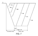
- Figure 7 shows a series of drive voltage profiles 140, 142, 144, 146, 148 and 150 (hereinafter 'drive pulses') that correspond to successively reduced fuel delivery volumes as calculated by the above described process implemented by the ICU 20.
- the discharge time T DISCHARGE is at a maximum value T DISCHARGE_MAX such that the injector is discharged by a maximum permitted value which is defined internally by the ICU 20. Therefore, a reduction in injector on time results in a reduction of the dwell period T DWELL from the maximum dwell period T DWELL_MAX corresponding to drive voltage profile 140, towards the minimum permitted dwell period T DWELL_MIN corresponding to drive voltage profile 144. It should be appreciated that the minimum dwell period T DWELL_MIN is a constraint imposed by the injector drive circuit 26 to ensure that electrical switching between a discharge phase and a charge phase can occur without causing damage to the injector drive circuit or the injector.
- the ICU 20 holds the dwell period constant at the minimum value T DWELL_MIN and reduces the discharge time period T DISCHARGE as can be seen by drive pulses 146, 148 and 150.
- the drive pulse that is applied to the injector has a corresponding frequency domain signature that includes at least one maximum F MAX and at least one minimum F MIN , as is indicated in an exemplary manner in Figure 5c
- the characteristics of the frequency domain signature arising from a given drive pulse are such that the dominant frequencies of the drive pulse coincide closely with the resonant frequency of the apparatus (e.g. the engine) in which the injector is installed.
- the characteristics of the drive pulse are modified in order to adapt the frequency domain signature thereof.
- the frequency domain signature of the drive pulse may be 'tuned' so that the energy peaks of the drive pulse are remote from and do not coincide with the resonant frequencies for a particular engine installation.
- the benefit of this invention is that a reduction in the amount of noise that is emitted from the injector is achieved.
- This invention is particularly applicable to circumstances in which the injector is driven to perform injection events in which a relatively small amount of fuel is delivered to an associated combustion chamber, for example a pilot injection or a main injection during an engine idle condition. It is during these engine operating conditions that the mechanical and combustion noise of the engine is relatively quiet such that the noise generated by the injectors is most noticeable.
- the ICU 20 modifies the delivery volume by increasing or decreasing the injector on time appropriately, as can be seen on Figure 8 by the injector drive pulses 200, 202 and 204 having successively decreasing values of injector on time T ON_1 , T ON_2 and T ON_3 .
- the dwell time for the drive pulse 204 represents the minimum dwell time as imposed by the switching requirements of the injector drive circuit 26. In order to decrease the delivery volume further, the dwell time must remain at this value so further reduction of injector on time results in the reduction of the discharge time T DISCHARGE , as can be seen by the drive pulses 206, 208 and 210 having injector on times of T ON_4 , T ON_5 and T ON_6 , respectively.
- the peak discharge current +I PEAK remains constant at a value I 1 such that the gradient of the discharge slope remains substantially constant.
- the ICU 20 holds the injector on time constant (at T ON_6 ) and reduces the peak current amplitude that is applied to the actuator during the discharge phase of an injection.
- T ON_6 the injector drive pulses 212, 214, 216 and 218 having successively reduced discharge gradients I 2 , I 3 , I 4 and I 5 , respectively.
- the injector discharge time period remains substantially constant at T DISCHARGE_1 .
- the ICU 20 reduces the discharge pulse time T DISCHARGE .
- T DISCHARGE This is shown on Figure 8 by the drive voltage profiles 220, 222 and 224 having successively reduced injector discharge time periods T DISCHARGE_2, T DISCHARGE_3 and T DISCHARGE_4 . It should be noted that for the drive voltage profiles 220, 222 and 224 the values of injector on time and peak current amplitude remain at their minimum threshold values T ON_6 and l 5 as has been described above.
- the drive pulse 224 represents the maximum dwell period that is possible for small values of needle lift in order to avoid injection instabilities. Therefore, in order to further reduce the fuel delivery volume, the ICU 20 holds the dwell period constant and reduces the discharge time period further as shown by drive pulses 226 and 228.
- the ICU 20 receives data relating to the prevailing operating conditions of the engine: for example engine speed, common rail fuel pressure, outside air temperature and the like.
- the ICU 20 receives data relating to the power requirement of the engine, such data being derived directly or indirectly from the accelerator pedal position of the vehicle.
- the ICU 20 calculates, at step 244, the value of injector on time T ON (hereinafter T ON_DEMAND ) that will provide the correct fuel delivery volume to generate the required power output from the engine by referring to one or more data maps stored in the memory of the ICU 20.
- the ICU 20 inputs the calculated value of T ON_DEMAND into three further functional modules represented by steps 246, 248 and 250.
- the ICU 20 refers to a first data map stored in its memory to calculate a tuned or revised value of injector on time (hereinafter T ON_TUNED ) based on the value of T ON_DEMAND and data relating to common rail fuel pressure.
- the data map relates values of T ON_DEMAND to T ON_TUNED to select a value for T ON_TUNED which takes into account the effects of the resonant frequency of the injector installation.
- the ICU 20 refers to a second data map stored in its memory to calculate a revised value of discharge time (hereinafter T DISCHARGE_TUNED ) based on the value of T ON_DEMAND and data relating to common rail fuel pressure.
- the second data map relates values of T ON_DEMAND to T DISCHARGE_TUNED to select a value for T DISCHARGE_TUNED which gives the required fuel volume delivery in conjunction with T ON_TUNED .
- the ICU 20 refers to a third data map stored in its memory to calculate a revised value of peak discharge current (hereinafter I TUNED ) based on the value of T ON_DEMAND and data relating to common rail fuel pressure.
- the third data map relates values of T ON_DEMAND to I TUNED to select a value for I TUNED which takes into account the amplitude of the resonant frequency of the injector installation.
- T ON_TUNED , T DISCHARGE_TUNED and I TUNED are thereafter used by the ICU 20 at step 252 to operate the injector via the injector drive circuit 26 to give the demanded fuel delivery.
- the tuned injector on time T ON_TUNED , the tuned discharge time T DISCHARGE_TUNED , and the tuned current I TUNED therefore all contribute to the fuelling.
- the first, second and third data maps are determined in an off line environment.
- the characteristics of the drive pulse are modified in steps 246, 248 and 250 in real time to ensure that the frequency composition of the drive pulse does not include energy peaks that reside in frequency bands consistent with the resonant frequencies of the injector installation.
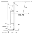
- FIGs 10 and 11 show a second embodiment of the invention which is a specific implementation of the tuned drive pulse concept described above.
- a drive pulse 300 is shown for a typical injection event that corresponds approximately to a medium engine load operating condition.
- the injector is discharged from a starting voltage level V1 to a predetermined voltage level V2 at which point the voltage remains for a significant dwell period before the injector is recharged back to the starting voltage level V1 to terminate the injection event.
- a typical drive pulse 302 that corresponds to a low engine load operating condition, for example when the engine is running at idle.
- the injector is discharged from the starting voltage level V1 at the same rate as for the drive pulse 300, but to a voltage level V3 which is greater than V2.
- the voltage remains at V3 for a very short dwell period, which is the minimum permissible dwell period as required by the switching characteristics of the injector drive circuit 26, before being recharged to the starting voltage V1.
- a drive current profile 304 that corresponds to the drive pulse 302 is shown in Figure 11.
- the drive current profile 304 has an injector on time period of T ON_A and a discharge time period of T DISCHARGE_A .
- a drive pulse 306 for an 'engine idle' operating condition that is modified in accordance with the second embodiment of the invention is also shown in Figure 10 and the corresponding drive current profile 308 is shown in Figure 11.
- the modification involves employing a less aggressive drive pulse in order to ameliorate the audible noise emissions of the injector at low engine loads.
- the injector is discharged at the same rate as the drive pulses 300 and 302 to avoid a reduction in initial rate of fuel injection.
- the discharge time period of the drive pulse 206 (shown as T DISCHARGE_B on Figure 11) is significantly shorter than the discharge time period T DISCHARGE_A for the drive pulse 302, the dwell time has been increased and the injector on time period T ON_B has been increased.
- the injector is discharged to a lower magnitude voltage V4, which reduces the axial displacement of the injector valve needle, but the total time for which the injector valve needle is disengaged from its seat is increased.
- Figures 12a and 12b show injector valve needle lift profiles (needle lift A and needle lift B) and delivery rate profiles (delivery rate A and delivery rate B) for each of the drive pulses 302, 306 respectively, of Figure 10.
- needle lift A corresponds to the drive voltage profile 302 that is known for an engine idle operating condition and shows the injector valve needle lifting rapidly to reach its maximum lift and then lowering substantially immediately.
- the peak delivery rate is relatively high but the delivery time is relatively short.
- needle lift B which corresponds to the drive voltage profile 306 modified in accordance with the second embodiment of the invention, includes a relatively low peak lift but the injector valve needle remains open for a longer period of time.
- the corresponding delivery rate B in Figure 13b has a lower peak delivery rate than delivery rate A but continues for a comparatively long period of time.
Landscapes
- Engineering & Computer Science (AREA)
- Chemical & Material Sciences (AREA)
- Combustion & Propulsion (AREA)
- Mechanical Engineering (AREA)
- General Engineering & Computer Science (AREA)
- Fuel-Injection Apparatus (AREA)
- Electrical Control Of Air Or Fuel Supplied To Internal-Combustion Engine (AREA)
Abstract
Description
- The invention relates to a method of operating a fuel injector. More specifically, the invention relates to a method of operating a piezoelectrically actuated fuel injector in order to reduce the level of noise that is generated by the injector.
- In a direct injection internal combustion engine, a fuel injector is provided to deliver a charge of atomised fuel into a combustion chamber prior to ignition. Typically, the fuel injector is mounted in a cylinder head of an engine with respect to the combustion chamber such that a tip of the injector protrudes slightly into the chamber to permit the fuel charge to be delivered thereto.
- One type of fuel injector that is particularly suited for use in a direct injection engine is a so-called piezoelectric injector. Such an injector allows precise control of the timing of an injection event and of the total volume of fuel that is delivered to the combustion chamber during the injection event. This permits accurate control over the combustion process which is beneficial for fuel efficiency and exhaust emissions.
- A known
piezoelectric injector 2 and its associatedcontrol system 3 is shown schematically in Figure 1. Thepiezoelectric injector 2 includes apiezoelectric actuator 4 that is operable to control the position of aninjector valve needle 6 relative to avalve needle seat 8. As known in the art, thepiezoelectric actuator 4 includes astack 7 of piezoelectric elements that expands and contacts in dependence on the voltage across thestack 7. The axial position, or 'lift', of thevalve needle 6 is controlled by applying a variable voltage 'V' to thepiezoelectric actuator 4. Although not shown in Figure 1, it should be appreciated that, in practice, the variable voltage would be applied to the actuator by connecting a power supply plug to the terminals of the injector. - Through application of an appropriate voltage across the actuator, the
valve needle 6 is caused either to disengage thevalve seat 8, in which case fuel is delivered into an associated combustion chamber (not shown) through a set ofnozzle outlets 10, or is caused to engage thevalve seat 8, in which case fuel delivery through theoutlets 10 is prevented. - For further background to the invention, an injector of this type is described in applicant's
European Patent No. EP 0955901 B . Such fuel injectors can be used in compression-ignition (diesel) engines or spark ignition (petrol) engines. - Although piezoelectric injectors are adept at delivering precise quantities of fuel with accurate timing, they also have associated disadvantages. For example, during use, a piezoelectric injector emits vibrations due to the frequency of the drive voltage that is applied to the piezoelectric actuator. The vibrations travel down the injector, or through an injector positioning/clamping arrangement, and are transmitted to the engine. The engine accentuates certain frequencies such that at least a portion of the vibrations can be detected by the human ear.
- At moderate and high engine speeds, the emitted noise of the injectors is drowned out by the combustion noise of the engine. However, at low engine speeds, particularly at an engine idle operating condition and with the bonnet/hood raised, the audible injector noise is apparent. The detectable noise contributes to the overall noise/vibration/harshness (NVH) characteristics of the vehicle.
- The optimisation of NVH characteristics is a significant factor in successful vehicle design since it influences the buying decision of the consumer. It is therefore desirable to reduce the amount of noise emitted by the injector in an effort to reduce the overall level of noise perceived by the user of the vehicle.
- Against this background, the invention provides a method of operating a fuel injector, the injector having a piezoelectric actuator operable by applying a drive pulse thereto, wherein the drive pulse has a frequency domain signature, the method including determining at least one resonant frequency of an injector installation in which the injector is received, in use, and modifying the drive pulse such that a maximum/maxima of the frequency domain signature is remote from or does not coincide with the determined resonant frequency of the injector installation.
- By configuring the drive pulse such that its dominant frequencies are remote from the or each resonant frequency of the injector installation, a substantial reduction in noise is achieved.
- The drive pulse may be defined by a plurality of drive pulse characteristics including a discharge time period, an injector on time period and a peak discharge/charge current amplitude such that the step of modifying the injector drive pulse includes modifying one or more of selected ones of said characteristics.
- In one embodiment, the method may include the steps of receiving a value that represents the demanded fuel volume and determining a tuned injector on time value by referring to a first data map relating the value to the tuned injector on time value, and using the determined tuned injector on time value for subsequent operation of the injector.
- Further the method may include determining a discharge time period value by referring to a second data map relating the value to the discharge time period value, and determining a peak discharge/charge current amplitude value by referring to a third data map relating the value to the peak discharge/charge current amplitude value. The determined values of discharge time period and peak discharge/charge current amplitude may be used for subsequent operation of the injector.
- In one embodiment, in order to reduce the volume of fuel delivered by the injector during a first series of successive injection events, the method includes reducing the injector on time period to a predetermined injector on time threshold value and, for subsequent reductions in fuel delivery volume, holding the injector on time period substantially constant and thereafter reducing the discharge time period.
- For a subsequent series of successive injection events, the injector on time period may be held substantially constant, the discharge time period may be held substantially constant, and the peak discharge/charge current amplitude may be reduced to a predetermined peak current threshold value in order to further reduce the volume of fuel that is delivered by the injector over the subsequent series of successive injection events.
- In an alternative embodiment, in order to reduce the volume of fuel delivered by the injector during a first series of successive injection events, the method includes reducing the injector on time period to a predetermined injector on time threshold value and, for subsequent reductions in fuel delivery volume, holding the injector on time period substantially constant and thereafter reducing the peak discharge/charge current amplitude to a predetermined peak current threshold value. In this embodiment, for a subsequent series of successive injection events, the injector on time period may be held substantially constant, the peak discharge/charge current amplitude may be held substantially constant, and the discharge time period may be reduced in order to further reduce the volume of fuel that is delivered by the injector.
- In another embodiment, where an injection comprises a plurality of injector drive pulses, for example in the form of first and second pilot drive pulses and a single main drive pulse, the temporal separation between successive drive pulses may be selected so as to modify the frequency domain signature of the drive pulse sequence such that a maximum of the frequency domain signature is remote from the determined resonant frequency of the injector installation. This provides further flexibility in modifying the characteristics of an injection event in order to achieve a reduction in emitted noise.
- In another aspect, the invention provides a computer program product comprising at least one computer program software portion which, when executed in an executing environment, is operable to implement the method as set forth above.
- In yet another aspect, the invention provides a data storage medium having the or each computer program product stored thereon.
- In another aspect, the invention provides a microcomputer provided with the data storage medium thereon.
- For the purpose of this description and claims, reference to a "series" of injection events should be taken to include one or more injection events.
- Reference has already been made to Figure 1 which is a schematic representation of a known
piezoelectric injector 2 and its associated control system, including an injector drive circuit. In order that it may be more readily understood, the invention will now be described with reference also to the following figures, in which: - Figure 2 is a circuit diagram of the injector drive circuit in Figure 1;
- Figure 3 is a flow chart of a known method of operating the circuit of Figure 2;
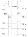
- Figures 4a, 4b and 4c are state diagrams of charge select, discharge select and injector select switches according to the known control method of Figure 3;
- Figures 4d and 4e are profiles of voltage measured across the terminals of the injector and drive current flowing through current sensing means of the injector drive circuit of Figure 1, according the method of Figure 3;
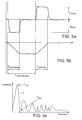
- Figure 5a is a drive current profile corresponding to the drive current profile in Figure 4e but filtered at approximately 20 kHz;
- Figure 5b is a drive voltage profile corresponding to the drive current profile in Figure 5a;
- Figure 5c is a frequency spectrum of the drive current profile of Figure 5a
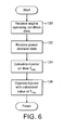
- Figure 6 is a flowchart of a known process that is implemented by the injector control unit in Figure 1;
- Figure 7 is a plurality of known drive voltage profiles illustrating a sequential reduction in fuel delivery volume;
- Figure 8 is a plurality of drive voltage profiles illustrating a sequential reduction in fuel delivery volume in accordance with a first embodiment of the invention;
- Figure 9 is a flowchart of a process according to the first embodiment of the invention that may be implemented by the injector control unit in Figure 1;
- Figure 10 is a graph comparing a known drive voltage profile with a drive voltage profile in accordance with a second embodiment of the invention;
- Figure 11 shows drive current profiles corresponding to the drive voltage profiles of Figure 10;
- Figure 12a and Figure 12b are graphs of needle lift and fuel delivery rate corresponding to the drive voltage profiles and drive current profiles of Figures 10 and 11;
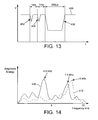
- Figure 13 is a drive voltage profile of a third embodiment of the invention; and
- Figure 14 is a frequency domain diagram associated with the drive voltage profile of Figure 13.
- Referring again to Figure 1, the
piezoelectric injector 2 is controlled by an injector control unit 20 (hereinafter 'ICU') that forms an integral part of an engine control unit 22 (ECU). TheECU 22 monitors a plurality ofengine parameters 24 and calculates an engine power requirement signal (not shown) which is input to theICU 20. In turn, theICU 20 calculates a required injection event sequence to provide the required power for the engine and operates aninjector drive circuit 26 accordingly. Theinjector drive circuit 26 is also shown as integral to theECU 22, although it should be appreciated that this is not essential to the invention. - In order to initiate an injection, the
injector drive circuit 26 causes the differential voltage between the high and low voltage terminals of the injector, V1 and V2, to transition from a high voltage (typically 200 V) at which no fuel delivery occurs, to a relatively low voltage (typically -30 V), which reduces the voltage of thepiezoelectric actuator 4 and therefore initiates fuel delivery. An injector responsive to this drive waveform is referred to as a 'de-energise to inject' injector and is operable to deliver one or more injections of fuel within a single injection event. For example, the injection event may include one or more so-called 'pre-' or 'pilot' injections, a main injection, and one or more 'post' injections. In general, several such injections within a single injection event are preferred to increase combustion efficiency of the engine. - Referring also to Figure 2, the
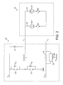
injector drive circuit 26 includes an injector charge/discharge switching circuit 30 (hereinafter 'switching circuit') that is connected to aninjector bank circuit 32 so as to control the voltage applied to a high side voltage input V1 and a low side voltage input V2 of thebank circuit 32. - The
injector bank circuit 32 includes first andsecond branches branch piezoelectric actuator 4 of eachinjector 2 is considered electrically equivalent to a capacitor, the voltage difference between V1 and V2 determining the amount of electrical charge stored by the actuator and, thus, the position of theinjector valve needle 8. - The switching
circuit 30 includes three input voltage rails: a high voltage rail VHI (typically 230 V), a mid voltage rail VMID (typically 30 V) and a ground connection GND. The switchingcircuit 30 is operable to connect the high side voltage input V1 of the injector bank circuit to either the high voltage rail VHI or the ground connection GND by means of first and second switches Q1, Q2 to which theinjector bank 32 is connected, through an inductor L. - The switching
circuit 30 is also provided with a diode D1 that connects the high side voltage input V1 of thebank circuit 32 to the high voltage rail VHI. The diode D1 is oriented to permit current to flow from the high side input V1 of thebank circuit 32 to the high voltage rail VHI but to prevent current flow from the high voltage rail VHI to the high side voltage input V1 of thebank circuit 32. - The first switch Q1, when activated, connects the high side input V1 of the selected injector to the ground connection GND via the inductor L. Therefore, charge from the injector is permitted to flow from the selected injector, through the inductor L and the first switch Q1 to the ground connection GND, thereby serving to discharge the selected injector during an injector discharge phase. Hereinafter, the first switch will therefore be referred to as the 'discharge select switch' Q1. A diode DQ1 is connected across the second switch Q2 and is oriented to permit current to flow from the inductor L to the high voltage rail VHI when the discharge select switch Q1 is deactivated, thus guarding against voltage peaks across the inductor L.
- In contrast, the second switch Q2, when activated, connects the high side input V1 of the selected injector to the high voltage rail VHI via the inductor L. In circumstances where the or each injector is discharged, activating the second switch Q2 causes charge to flow from the high voltage rail VHI, through the second switch Q2 and the inductor L, and into the injector, during an injector charge phase, until an equilibrium voltage is reached (the point at which the voltage due to charge stored by the actuator equals the voltage difference between the high side and low side voltage inputs V1, V2). Hereinafter, the second switch will be referred to as the 'charge select switch' Q2.
- A diode DQ2 is connected across the discharge select switch Q1 and is oriented to permit current to flow from the ground connection GND through the inductor L to the high side input V1 when the charge select switch Q2 is deactivated, thus guarding against voltage peaks across the inductor L.
- It should be appreciated that the inductor L constitutes a bidirectional current path since current flows in a first direction through the inductor L during the discharge phase and in a second, opposite direction during the injector charge phase.
- The low side voltage input V2 of the
injector bank circuit 32 is connected to the mid voltage rail VMID via avoltage sense resistor 44. A current sensing and comparator means 50 (hereinafter 'comparator module') is connected in parallel with thesense resistor 44 and is operable to monitor the current flowing therethrough. In response to the current flowing through theresistor 44, thecomparator module 50 outputs a control signal 52 (hereafter QCONTROL) that controls the activation status of the discharge select switch Q1 and the charge select switch Q2 so as to regulate the peak current flowing out of, or into, the operating injector. In effect, thecomparator module 50 controls the activation status of the switches Q1 and Q2 to 'chop' the injector current between maximum and minimum current limits and achieve a predetermined average charge or discharge current. By this means, a high degree of control is afforded over the amount of electrical charge that is transferred off of thestack 7 during a discharge phase and, conversely, onto thestack 7 during a charge phase. - The operation of the
injector drive circuit 26 during a typical discharge phase, followed by a charge phase, is described below with reference to Figure 3 and Figures 4a to 4e. - Initially, prior to time T0, the
injector drive circuit 26 is at equilibrium, that is to say both injectors INJ1 and INJ2 are fully charged such that no fuel injection is taking place. In these circumstances, theICU 20 is in a wait state, indicated atstep 100, awaiting an injection command signal from theECU 22. - Following receipt of an injection command from the
ECU 22 atstep 102, theICU 20 selects the injector that it is required to operate atstep 104. For the purposes of this description, the selected injector is the first injector, INJ1. At substantially the same time, theICU 20 initiates the discharge phase by enabling the discharge select switch Q1 so as to cause the injector INJ1 to discharge. A predetermined average discharge current through the injector is ensured by thecomparator module 50 outputting the QCONTROL signal between T0 and T1 to repeatedly deactivate and reactivate the discharge select switch Q1 such that the current remains within predetermined limits. - The
ICU 20 applies the predetermined average discharge current to the stack for a period of time (from T0 to T1) sufficient to transfer a predetermined amount of charge off of the stack (it should be appreciated that the discharge phase timings are read from a timing map by the ICU 20). - At time T1 (step 106), the
ICU 20 deactivates the first injector select switch QS1 and disables the discharge select switch Q1, thus terminating the control signal QCONTROL, to prevent the injector discharging further. Thus during the time period T0 to T1 the stack voltage drops from a charged voltage level VCHARGE to a discharged voltage level VDISCHARGE, as indicated in Figure 4d. - At
step 108, theICU 20 maintains the injector INJ1 at the discharged voltage level VDISCHARGE for a predetermined dwell period, T1 to T2, such that theinjector valve needle 8 is held open to perform an injection event. At the end of the dwell period, atstep 110, theICU 20 enables the charge select switch Q2 in order to start the injector charge phase so as to terminate injection. As a result, the high side voltage input V1 of theinjector bank circuit 32 is connected to the high voltage rail VHI and charge begins to transfer into the injector INJ1. - As the current flowing into the injector increases, the
comparator module 50 monitors the current flowing through thesense resistor 44 and controls the activation status of the charge select switch Q2, via the control signal QCONTROL to ensure a predetermined average charging current level. Between time T2 and T3 theICU 20 applies the predetermined average charging current to the stack for a period of time sufficient to transfer a predetermined amount of charge onto the stack. At time T3 (step 112), theICU 20 disables the charge select switch Q2 and returns to the waitingstep 100 ready for initiation of another injection event. - Figures 5a and 5b show the principle characteristics of an injector drive current profile and a drive voltage profile as described above. In Figure 5a, the drive current profile is substantially identical to that shown in Figure 4d, but is filtered at 20kHz that represents an upper threshold of the frequency response of the
piezoelectric actuator 4. In practice, the chopping frequency that is applied to the piezoelectric actuator is in the order of 500kHz although this is too high to result in movement of the piezoelectric actuator at a similar frequency. - The injector drive pulse is defined by the following characteristics:
- i) a discharge pulse time (TDISCHARGE)
- ii) a charge pulse time (TCHARGE)
- iii) an 'injector on time' (TON) i.e. the interval between the start of stack discharge and the start of stack charge
- iv) a positive peak current amplitude (+IPEAK)
- v) a negative current amplitude (-IPEAK)
- In order to vary the power output of the engine, it is necessary to vary the quantity of fuel that is delivered to the combustion chambers of the engine during each injection event. It is known for the
ICU 20 to perform this function by varying the value of injector on time TON, which is the sum of the discharge pulse time TDISCHARGE and a dwell period defined between the end of the discharge phase and the start of the charge phase. - Referring to Figure 6, at
step 120 theICU 20 receives data relating to the prevailing operating conditions of the engine: for example, engine speed, common rail fuel pressure, outside air temperature and the like. Then, atstep 122, theICU 20 receives data relating to the power requirement of the engine, such data being derived directly or indirectly from the accelerator pedal position of the vehicle. Following the acquisition of the vehicle data atsteps ICU 20 calculates, atstep 124, the value of injector on time TON that will provide the correct fuel delivery volume to generate the required power output from the engine by referring to one or more data maps stored in the memory of theICU 20. Atstep 126, theICU 20 operates theinjector drive circuit 26 according to the calculated value of TON. - Figure 7 shows a series of
drive voltage profiles ICU 20. - For the
drive pulses ICU 20. Therefore, a reduction in injector on time results in a reduction of the dwell period TDWELL from the maximum dwell period T DWELL_MAX corresponding to drivevoltage profile 140, towards the minimum permitted dwell period T DWELL_MIN corresponding to drivevoltage profile 144. It should be appreciated that the minimum dwell period T DWELL_MIN is a constraint imposed by theinjector drive circuit 26 to ensure that electrical switching between a discharge phase and a charge phase can occur without causing damage to the injector drive circuit or the injector. - In order to reduce the fuel delivery volume further, the
ICU 20 holds the dwell period constant at the minimum value TDWELL_MIN and reduces the discharge time period TDISCHARGE as can be seen bydrive pulses - The inventors have now recognised that the drive pulse that is applied to the injector has a corresponding frequency domain signature that includes at least one maximum FMAX and at least one minimum FMIN, as is indicated in an exemplary manner in Figure 5c It has been recognised that at certain delivery volumes, particularly at engine idle operating conditions, the characteristics of the frequency domain signature arising from a given drive pulse are such that the dominant frequencies of the drive pulse coincide closely with the resonant frequency of the apparatus (e.g. the engine) in which the injector is installed. In accordance with the invention, therefore, the characteristics of the drive pulse are modified in order to adapt the frequency domain signature thereof. In this way, the frequency domain signature of the drive pulse may be 'tuned' so that the energy peaks of the drive pulse are remote from and do not coincide with the resonant frequencies for a particular engine installation. The benefit of this invention is that a reduction in the amount of noise that is emitted from the injector is achieved.
- This invention is particularly applicable to circumstances in which the injector is driven to perform injection events in which a relatively small amount of fuel is delivered to an associated combustion chamber, for example a pilot injection or a main injection during an engine idle condition. It is during these engine operating conditions that the mechanical and combustion noise of the engine is relatively quiet such that the noise generated by the injectors is most noticeable.
- A first embodiment of the invention will now be described with reference to Figure 8. In this embodiment, for injection events in which a relatively high volume of fuel is required to be delivered, for example during medium to high engine load conditions, the
ICU 20 modifies the delivery volume by increasing or decreasing the injector on time appropriately, as can be seen on Figure 8 by theinjector drive pulses - The dwell time for the
drive pulse 204 represents the minimum dwell time as imposed by the switching requirements of theinjector drive circuit 26. In order to decrease the delivery volume further, the dwell time must remain at this value so further reduction of injector on time results in the reduction of the discharge time TDISCHARGE, as can be seen by thedrive pulses - It should be noted that for each of the
injector drive pulses - Up to this point, the way in which the fuel delivery volume is reduced is the same as that described with reference to Figures 6 and 7. However, the inventors have recognised that injector noise is particularly severe below a threshold of injector on time, more specifically approximately 200µs, which is shown on Figure 8 as TON_6.
- It has been observed that injector noise at injector on time values below the threshold of TON_6 is more severe because the reciprocal of the injector on time value is approximately equal to the resonant frequency of the injector installation i.e. the engine in which the injector is received, in use.
- Therefore, in order to reduce the delivery volume below that which is achievable at the first threshold, the
ICU 20 holds the injector on time constant (at TON_6) and reduces the peak current amplitude that is applied to the actuator during the discharge phase of an injection. On Figure 8, this can be seen by theinjector drive pulses injector drive pulses - However, it is not possible to reduce the value peak current amplitude indefinitely since too low a value may adversely affect the fuel delivery rate. Due to the limited range within which it is possible to reduce the value of +IPEAK, if it required to further reduce the total volume of fuel delivered during an injection event, the
ICU 20 reduces the discharge pulse time TDISCHARGE. This is shown on Figure 8 by thedrive voltage profiles drive voltage profiles - The
drive pulse 224 represents the maximum dwell period that is possible for small values of needle lift in order to avoid injection instabilities. Therefore, in order to further reduce the fuel delivery volume, theICU 20 holds the dwell period constant and reduces the discharge time period further as shown bydrive pulses - Referring to Figure 9, which represents the process carried out by the
ICU 20 to implement this embodiment, atstep 240 theICU 20 receives data relating to the prevailing operating conditions of the engine: for example engine speed, common rail fuel pressure, outside air temperature and the like. Atstep 242 theICU 20 receives data relating to the power requirement of the engine, such data being derived directly or indirectly from the accelerator pedal position of the vehicle. Following the acquisition of the vehicle data atsteps ICU 20 calculates, atstep 244, the value of injector on time TON (hereinafter TON_DEMAND) that will provide the correct fuel delivery volume to generate the required power output from the engine by referring to one or more data maps stored in the memory of theICU 20. However, instead of using the value of TON_DEMAND directly to operate theinjector drive circuit 26, as is consistent with the known method of controlling the injector as described above with reference to Figure 6, theICU 20 inputs the calculated value of TON_DEMAND into three further functional modules represented bysteps - At
step 246, theICU 20 refers to a first data map stored in its memory to calculate a tuned or revised value of injector on time (hereinafter TON_TUNED) based on the value of TON_DEMAND and data relating to common rail fuel pressure. The data map relates values of TON_DEMAND to TON_TUNED to select a value for TON_TUNED which takes into account the effects of the resonant frequency of the injector installation. - At
step 248, theICU 20 refers to a second data map stored in its memory to calculate a revised value of discharge time (hereinafter TDISCHARGE_TUNED) based on the value of TON_DEMAND and data relating to common rail fuel pressure. The second data map relates values of TON_DEMAND to TDISCHARGE_TUNED to select a value for TDISCHARGE_TUNED which gives the required fuel volume delivery in conjunction with TON_TUNED. - At
step 250, theICU 20 refers to a third data map stored in its memory to calculate a revised value of peak discharge current (hereinafter ITUNED) based on the value of TON_DEMAND and data relating to common rail fuel pressure. The third data map relates values of TON_DEMAND to ITUNED to select a value for ITUNED which takes into account the amplitude of the resonant frequency of the injector installation. - The values of TON_TUNED, TDISCHARGE_TUNED and ITUNED are thereafter used by the
ICU 20 atstep 252 to operate the injector via theinjector drive circuit 26 to give the demanded fuel delivery. The tuned injector on time TON_TUNED, the tuned discharge time TDISCHARGE_TUNED, and the tuned current ITUNED, therefore all contribute to the fuelling. - The first, second and third data maps are determined in an off line environment. The characteristics of the drive pulse are modified in
steps - Figures 10 and 11 show a second embodiment of the invention which is a specific implementation of the tuned drive pulse concept described above. In Figure 10, a
drive pulse 300 is shown for a typical injection event that corresponds approximately to a medium engine load operating condition. As can be seen, the injector is discharged from a starting voltage level V1 to a predetermined voltage level V2 at which point the voltage remains for a significant dwell period before the injector is recharged back to the starting voltage level V1 to terminate the injection event. - Also shown in Figure 10 is a
typical drive pulse 302 that corresponds to a low engine load operating condition, for example when the engine is running at idle. As can be seen, the injector is discharged from the starting voltage level V1 at the same rate as for thedrive pulse 300, but to a voltage level V3 which is greater than V2. The voltage remains at V3 for a very short dwell period, which is the minimum permissible dwell period as required by the switching characteristics of theinjector drive circuit 26, before being recharged to the starting voltage V1. A drivecurrent profile 304 that corresponds to thedrive pulse 302 is shown in Figure 11. The drivecurrent profile 304 has an injector on time period of TON_A and a discharge time period of TDISCHARGE_A. - A
drive pulse 306 for an 'engine idle' operating condition that is modified in accordance with the second embodiment of the invention is also shown in Figure 10 and the corresponding drive current profile 308 is shown in Figure 11. The modification involves employing a less aggressive drive pulse in order to ameliorate the audible noise emissions of the injector at low engine loads. As can be seen, the injector is discharged at the same rate as thedrive pulses drive pulse 302, the dwell time has been increased and the injector on time period TON_B has been increased. As a result, the injector is discharged to a lower magnitude voltage V4, which reduces the axial displacement of the injector valve needle, but the total time for which the injector valve needle is disengaged from its seat is increased. - The effect of the modified drive voltage profile can be seen from Figures 12a and 12b, which show injector valve needle lift profiles (needle lift A and needle lift B) and delivery rate profiles (delivery rate A and delivery rate B) for each of the
drive pulses - In Figure 12a, needle lift A corresponds to the
drive voltage profile 302 that is known for an engine idle operating condition and shows the injector valve needle lifting rapidly to reach its maximum lift and then lowering substantially immediately. Referring to the delivery rate A in Figure 12b, the peak delivery rate is relatively high but the delivery time is relatively short. - In contrast needle lift B, which corresponds to the
drive voltage profile 306 modified in accordance with the second embodiment of the invention, includes a relatively low peak lift but the injector valve needle remains open for a longer period of time. Similarly, the corresponding delivery rate B in Figure 13b has a lower peak delivery rate than delivery rate A but continues for a comparatively long period of time.
Claims (13)
- A method of operating a fuel injector having a piezoelectric actuator operable by applying a drive pulse thereto, wherein the drive pulse has a frequency domain signature, the method including;
determining at least one resonant frequency of an injector installation in which the injector is received, in use; and
modifying the drive pulse such that a maximum of the frequency domain signature thereof is remote from the determined resonant frequency of the injector installation. - The method of claim 1, wherein the drive pulse is defined by two or more drive pulse characteristics including a discharge time period (TDISCHARGE), an injector on time period (TON), and a peak discharge/charge current amplitude (I), wherein the step of modifying the injector drive pulse includes modifying one or more selected ones of said drive pulse characteristics.
- The method of claim 2, wherein, in order to reduce the volume of fuel delivered by the injector during a first series of successive injection events, the method includes reducing the injector on time period (TON) to a predetermined injector on time threshold value (TON_6) and, for subsequent reductions in fuel delivery volume, holding the injector on time period substantially constant and thereafter reducing the discharge time period (TDISCHARGE).
- The method of claim 3, wherein, for a subsequent series of successive injection events, the method further includes holding the discharge time period (TDISCHARGE) substantially constant and reducing the peak discharge/charge current amplitude (I) to a predetermined peak current threshold value (I5).
- The method of claim 2, wherein, in order to reduce the volume of fuel delivered by the injector during a first series of successive injection events, the method includes reducing the injector on time period (TON) to a predetermined injector on time threshold value (TON_6) and, for subsequent reductions in fuel delivery volume, holding the injector on time period (TON) substantially constant and thereafter reducing the peak discharge/charge current amplitude (I) to a predetermined peak current threshold value (I5).
- The method of claim 5, wherein, for a subsequent series of successive injection events, the method further includes holding the injector on time period substantially constant at the predetermined injector on time threshold value (TON_6), holding the peak discharge/charge current amplitude at the predetermined peak current threshold value (I5), and reducing the discharge time period (TDISCHARGE) in order to further reduce the volume of fuel delivered by the injector, in use.
- The method of claim 2, including receiving a value (TON_DEMAND) that represents the demanded fuel volume and determining a tuned injector on time value (TON_TUNED) by referring to a first data map relating the value (TON_DEMAND) to the tuned injector on time value (TON_TUNED), and using the determined tuned injector on time value (TON_TUNED) for subsequent operation of the injector.
- The method of claim 7, further including determining a discharge time period value (TDISCHARGE_TUNED) by referring to a second data map relating the value (TON_DEMAND) to the discharge time period value (TDISCHARGE_TUNED), and using the determined discharge time period value (TDISCHARGE_TUNED) for subsequent operation of the injector.
- The method of claim 7 or claim 8, further including determining a peak discharge/charge current amplitude value (ITUNED) by referring to a third data map relating the value (TON_DEMAND) to the peak discharge/charge current amplitude value (ITUNED), and using the determined peak discharge/charge current amplitude value (ITUNED) for subsequent operation of the injector.
- A method of operating a fuel injector having a piezoelectric actuator, the method comprising:determining at least one resonant frequency of an injector installation in which the injector is received, in use,applying a drive pulse to the actuator, the drive pulse comprising first, second and third injection drive pulses and having a frequency domain signature; andselecting a separation time period between the first injection drive pulse and the second injection drive pulse and/or a separation time period between the second injection drive pulse and the third injection drive pulse so as to modify the frequency domain signature of the drive pulse such that a maximum of the frequency domain signature is remote from the determined resonant frequency of the injector installation.
- A computer program product comprising at least one computer program software portion which, when executed in an executing environment, is operable to implement the method of any one of claims 1 to 10.
- A data storage medium having the or each software portion of claim 11 stored thereon.
- A microcomputer provided with the data storage medium of claim 12 thereon.
Applications Claiming Priority (2)
| Application Number | Priority Date | Filing Date | Title |
|---|---|---|---|
| GB0610229A GB0610229D0 (en) | 2006-05-23 | 2006-05-23 | A method of operating a fuel injector |
| GB0617094A GB0617094D0 (en) | 2006-08-30 | 2006-08-30 | A method of operating a fuel injector |
Publications (3)
| Publication Number | Publication Date |
|---|---|
| EP1860310A2 true EP1860310A2 (en) | 2007-11-28 |
| EP1860310A3 EP1860310A3 (en) | 2008-08-27 |
| EP1860310B1 EP1860310B1 (en) | 2015-08-12 |
Family
ID=38440275
Family Applications (1)
| Application Number | Title | Priority Date | Filing Date |
|---|---|---|---|
| EP07252080.2A Not-in-force EP1860310B1 (en) | 2006-05-23 | 2007-05-21 | Method of operating a fuel injector |
Country Status (4)
| Country | Link |
|---|---|
| US (1) | US7856963B2 (en) |
| EP (1) | EP1860310B1 (en) |
| JP (1) | JP4545775B2 (en) |
| HU (1) | HUE025390T2 (en) |
Cited By (1)
| Publication number | Priority date | Publication date | Assignee | Title |
|---|---|---|---|---|
| DE102007060697A1 (en) * | 2007-12-17 | 2009-06-18 | Bayerische Motoren Werke Aktiengesellschaft | Fluid measuring device operating device for combustion chamber of internal-combustion engine of motor vehicle, has actuator, where durations are assigned to points and optimized with respect to oscillations at contacting |
Families Citing this family (10)
| Publication number | Priority date | Publication date | Assignee | Title |
|---|---|---|---|---|
| ATE450705T1 (en) * | 2007-02-02 | 2009-12-15 | Delphi Tech Inc | METHOD FOR OPERATING A PIEZOELECTRIC ACTUATOR |
| DE102007010263B3 (en) * | 2007-03-02 | 2008-04-10 | Siemens Ag | Operation device for piezoactuator used in e.g. fuel injection valve for vehicle internal combustion (IC) engine, uses two energy control units, each producing control signal for current threshold value of charging current of piezoactuator |
| DE102008027516B3 (en) * | 2008-06-10 | 2010-04-01 | Continental Automotive Gmbh | Method for injection quantity deviation detection and correction of an injection quantity and injection system |
| JP5204156B2 (en) * | 2010-06-22 | 2013-06-05 | トヨタ自動車株式会社 | Fuel injection control device for internal combustion engine |
| DE102011003751B4 (en) * | 2011-02-08 | 2021-06-10 | Vitesco Technologies GmbH | Injector |
| DE102012213883B4 (en) * | 2012-08-06 | 2015-03-26 | Continental Automotive Gmbh | Equalization of the current flow through a fuel injector for different partial injection processes of a multiple injection |
| CN105370423B (en) * | 2014-08-19 | 2019-11-15 | 马涅蒂-马瑞利公司 | Method for controlling injection in the cylinder combustion cycle of an indirect injection internal combustion engine |
| US10227890B2 (en) | 2016-08-18 | 2019-03-12 | Delavan, Inc. | Resonant modes in sprays |
| US10401398B2 (en) | 2017-03-03 | 2019-09-03 | Woodward, Inc. | Fingerprinting of fluid injection devices |
| JP6572951B2 (en) * | 2017-09-12 | 2019-09-11 | マツダ株式会社 | Engine fuel injection control device |
Citations (3)
| Publication number | Priority date | Publication date | Assignee | Title |
|---|---|---|---|---|
| EP0995899A2 (en) | 1998-07-01 | 2000-04-26 | Isuzu Motors Limited | Piezoelectric actuator and fuel-injection apparatus using the actuator |
| EP0955901B1 (en) | 1996-11-16 | 2003-04-23 | CAP Incorporated | Tight puncture seal |
| EP1398487A1 (en) | 2002-09-13 | 2004-03-17 | Renault s.a.s. | Control method and apparatus for a piezoelectric injector |
Family Cites Families (11)
| Publication number | Priority date | Publication date | Assignee | Title |
|---|---|---|---|---|
| US4784102A (en) * | 1984-12-25 | 1988-11-15 | Nippon Soken, Inc. | Fuel injector and fuel injection system |
| DE19535419A1 (en) * | 1995-09-23 | 1997-03-27 | Bosch Gmbh Robert | Method and device for controlling an actuator |
| JP3716532B2 (en) * | 1997-02-14 | 2005-11-16 | トヨタ自動車株式会社 | Fuel injection device |
| DE10146068A1 (en) | 2001-09-19 | 2003-04-03 | Fev Motorentech Gmbh | Dosed injection of liquid under pressure into reaction chamber involves continuously varying time between successive injection valve strokes to prevent system resonances |
| EP1302650B1 (en) * | 2001-10-12 | 2008-05-07 | Isuzu Motors Limited | Compression-ignition internal combustion engine |
| JP2004190653A (en) * | 2002-10-18 | 2004-07-08 | Ngk Insulators Ltd | Liquid injection apparatus |
| JP4353781B2 (en) * | 2003-02-27 | 2009-10-28 | 株式会社日本自動車部品総合研究所 | Piezo actuator drive circuit |
| DE10311350B4 (en) | 2003-03-14 | 2006-06-01 | Siemens Ag | Method and device for reducing sound emissions and high-frequency vibrations of a piezoelectric actuator |
| US7139655B2 (en) * | 2004-04-20 | 2006-11-21 | Nissan Motor Co., Ltd. | Intake air parameter estimating device for internal combustion engine |
| JP4462079B2 (en) * | 2004-11-11 | 2010-05-12 | トヨタ自動車株式会社 | Control device for internal combustion engine |
| DE602006004668D1 (en) * | 2005-10-06 | 2009-02-26 | Delphi Tech Inc | Method for controlling an injection valve |
-
2007
- 2007-05-21 HU HUE07252080A patent/HUE025390T2/en unknown
- 2007-05-21 EP EP07252080.2A patent/EP1860310B1/en not_active Not-in-force
- 2007-05-22 US US11/805,284 patent/US7856963B2/en not_active Expired - Fee Related
- 2007-05-23 JP JP2007136104A patent/JP4545775B2/en not_active Expired - Fee Related
Patent Citations (3)
| Publication number | Priority date | Publication date | Assignee | Title |
|---|---|---|---|---|
| EP0955901B1 (en) | 1996-11-16 | 2003-04-23 | CAP Incorporated | Tight puncture seal |
| EP0995899A2 (en) | 1998-07-01 | 2000-04-26 | Isuzu Motors Limited | Piezoelectric actuator and fuel-injection apparatus using the actuator |
| EP1398487A1 (en) | 2002-09-13 | 2004-03-17 | Renault s.a.s. | Control method and apparatus for a piezoelectric injector |
Cited By (2)
| Publication number | Priority date | Publication date | Assignee | Title |
|---|---|---|---|---|
| DE102007060697A1 (en) * | 2007-12-17 | 2009-06-18 | Bayerische Motoren Werke Aktiengesellschaft | Fluid measuring device operating device for combustion chamber of internal-combustion engine of motor vehicle, has actuator, where durations are assigned to points and optimized with respect to oscillations at contacting |
| DE102007060697B4 (en) * | 2007-12-17 | 2017-10-05 | Bayerische Motoren Werke Aktiengesellschaft | Apparatus for operating a Fluidzumessvorrichtung |
Also Published As
| Publication number | Publication date |
|---|---|
| JP2007315389A (en) | 2007-12-06 |
| EP1860310A3 (en) | 2008-08-27 |
| US20070273246A1 (en) | 2007-11-29 |
| HUE025390T2 (en) | 2016-02-29 |
| JP4545775B2 (en) | 2010-09-15 |
| EP1860310B1 (en) | 2015-08-12 |
| US7856963B2 (en) | 2010-12-28 |
Similar Documents
| Publication | Publication Date | Title |
|---|---|---|
| EP1860310B1 (en) | Method of operating a fuel injector | |
| EP2105599B1 (en) | Internal combustion engine controller | |
| US8649151B2 (en) | Injector drive circuit | |
| JP5198496B2 (en) | Engine control unit for internal combustion engines | |
| JP4148127B2 (en) | Fuel injection device | |
| EP1860309B1 (en) | Improvements relating to fuel injector control | |
| EP1887205B1 (en) | Improvements relating to fuel injector control | |
| JP2008240544A (en) | Fuel injection control device and fuel injection device | |
| EP2045459B1 (en) | A method of controlling fuel injection apparatus | |
| JP4032356B2 (en) | Fuel injection device | |
| US8154840B2 (en) | Fuel injector control | |
| EP2290211A1 (en) | Power supply arrangement for a fuel injector drive circuit | |
| US7576473B2 (en) | Method of operating a piezoelectric actuator | |
| JP2001241344A (en) | Method and apparatus for controlling an electromagnetic quantity control valve for demand control of a high pressure pump in a fuel supply system of an internal combustion engine | |
| US20070273247A1 (en) | Controller for a fuel injector and a method of operating a fuel injector | |
| EP1927742A1 (en) | A method of operating a piezoelectric device | |
| EP1860308A1 (en) | Method of operating a fuel injector | |
| CN111527296B (en) | Method for regulating the output voltage of a DC-DC voltage converter of a control computer of an engine of a motor vehicle | |
| EP1927741A1 (en) | A method of operating a piezoelectric device |
Legal Events
| Date | Code | Title | Description |
|---|---|---|---|
| PUAI | Public reference made under article 153(3) epc to a published international application that has entered the european phase |
Free format text: ORIGINAL CODE: 0009012 |
|
| AK | Designated contracting states |
Kind code of ref document: A2 Designated state(s): AT BE BG CH CY CZ DE DK EE ES FI FR GB GR HU IE IS IT LI LT LU LV MC MT NL PL PT RO SE SI SK TR |
|
| AX | Request for extension of the european patent |
Extension state: AL BA HR MK YU |
|
| PUAL | Search report despatched |
Free format text: ORIGINAL CODE: 0009013 |
|
| AK | Designated contracting states |
Kind code of ref document: A3 Designated state(s): AT BE BG CH CY CZ DE DK EE ES FI FR GB GR HU IE IS IT LI LT LU LV MC MT NL PL PT RO SE SI SK TR |
|
| AX | Request for extension of the european patent |
Extension state: AL BA HR MK RS |
|
| 17P | Request for examination filed |
Effective date: 20081209 |
|
| AKX | Designation fees paid |
Designated state(s): AT BE BG CH CY CZ DE DK EE ES FI FR GB GR HU IE IS IT LI LT LU LV MC MT NL PL PT RO SE SI SK TR |
|
| RAP1 | Party data changed (applicant data changed or rights of an application transferred) |
Owner name: DELPHI TECHNOLOGIES HOLDING S.A.R.L. |
|
| RAP1 | Party data changed (applicant data changed or rights of an application transferred) |
Owner name: DELPHI INTERNATIONAL OPERATIONS LUXEMBOURG S.A.R.L |
|
| GRAP | Despatch of communication of intention to grant a patent |
Free format text: ORIGINAL CODE: EPIDOSNIGR1 |
|
| INTG | Intention to grant announced |
Effective date: 20150320 |
|
| GRAS | Grant fee paid |
Free format text: ORIGINAL CODE: EPIDOSNIGR3 |
|
| GRAA | (expected) grant |
Free format text: ORIGINAL CODE: 0009210 |
|
| AK | Designated contracting states |
Kind code of ref document: B1 Designated state(s): AT BE BG CH CY CZ DE DK EE ES FI FR GB GR HU IE IS IT LI LT LU LV MC MT NL PL PT RO SE SI SK TR |
|
| REG | Reference to a national code |
Ref country code: GB Ref legal event code: FG4D |
|
| REG | Reference to a national code |
Ref country code: CH Ref legal event code: EP |
|
| REG | Reference to a national code |
Ref country code: AT Ref legal event code: REF Ref document number: 742377 Country of ref document: AT Kind code of ref document: T Effective date: 20150815 |
|
| REG | Reference to a national code |
Ref country code: IE Ref legal event code: FG4D |
|
| REG | Reference to a national code |
Ref country code: DE Ref legal event code: R096 Ref document number: 602007042523 Country of ref document: DE |
|
| REG | Reference to a national code |
Ref country code: LT Ref legal event code: MG4D |
|
| REG | Reference to a national code |
Ref country code: AT Ref legal event code: MK05 Ref document number: 742377 Country of ref document: AT Kind code of ref document: T Effective date: 20150812 |
|
| REG | Reference to a national code |
Ref country code: NL Ref legal event code: MP Effective date: 20150812 |
|
| PG25 | Lapsed in a contracting state [announced via postgrant information from national office to epo] |
Ref country code: LT Free format text: LAPSE BECAUSE OF FAILURE TO SUBMIT A TRANSLATION OF THE DESCRIPTION OR TO PAY THE FEE WITHIN THE PRESCRIBED TIME-LIMIT Effective date: 20150812 Ref country code: FI Free format text: LAPSE BECAUSE OF FAILURE TO SUBMIT A TRANSLATION OF THE DESCRIPTION OR TO PAY THE FEE WITHIN THE PRESCRIBED TIME-LIMIT Effective date: 20150812 Ref country code: LV Free format text: LAPSE BECAUSE OF FAILURE TO SUBMIT A TRANSLATION OF THE DESCRIPTION OR TO PAY THE FEE WITHIN THE PRESCRIBED TIME-LIMIT Effective date: 20150812 Ref country code: GR Free format text: LAPSE BECAUSE OF FAILURE TO SUBMIT A TRANSLATION OF THE DESCRIPTION OR TO PAY THE FEE WITHIN THE PRESCRIBED TIME-LIMIT Effective date: 20151113 |
|
| PG25 | Lapsed in a contracting state [announced via postgrant information from national office to epo] |
Ref country code: IS Free format text: LAPSE BECAUSE OF FAILURE TO SUBMIT A TRANSLATION OF THE DESCRIPTION OR TO PAY THE FEE WITHIN THE PRESCRIBED TIME-LIMIT Effective date: 20151212 Ref country code: AT Free format text: LAPSE BECAUSE OF FAILURE TO SUBMIT A TRANSLATION OF THE DESCRIPTION OR TO PAY THE FEE WITHIN THE PRESCRIBED TIME-LIMIT Effective date: 20150812 Ref country code: ES Free format text: LAPSE BECAUSE OF FAILURE TO SUBMIT A TRANSLATION OF THE DESCRIPTION OR TO PAY THE FEE WITHIN THE PRESCRIBED TIME-LIMIT Effective date: 20150812 Ref country code: SE Free format text: LAPSE BECAUSE OF FAILURE TO SUBMIT A TRANSLATION OF THE DESCRIPTION OR TO PAY THE FEE WITHIN THE PRESCRIBED TIME-LIMIT Effective date: 20150812 Ref country code: PL Free format text: LAPSE BECAUSE OF FAILURE TO SUBMIT A TRANSLATION OF THE DESCRIPTION OR TO PAY THE FEE WITHIN THE PRESCRIBED TIME-LIMIT Effective date: 20150812 Ref country code: PT Free format text: LAPSE BECAUSE OF FAILURE TO SUBMIT A TRANSLATION OF THE DESCRIPTION OR TO PAY THE FEE WITHIN THE PRESCRIBED TIME-LIMIT Effective date: 20151214 |
|
| REG | Reference to a national code |
Ref country code: HU Ref legal event code: AG4A Ref document number: E025390 Country of ref document: HU |
|
| PG25 | Lapsed in a contracting state [announced via postgrant information from national office to epo] |
Ref country code: NL Free format text: LAPSE BECAUSE OF FAILURE TO SUBMIT A TRANSLATION OF THE DESCRIPTION OR TO PAY THE FEE WITHIN THE PRESCRIBED TIME-LIMIT Effective date: 20150812 |
|
| PG25 | Lapsed in a contracting state [announced via postgrant information from national office to epo] |
Ref country code: EE Free format text: LAPSE BECAUSE OF FAILURE TO SUBMIT A TRANSLATION OF THE DESCRIPTION OR TO PAY THE FEE WITHIN THE PRESCRIBED TIME-LIMIT Effective date: 20150812 Ref country code: DK Free format text: LAPSE BECAUSE OF FAILURE TO SUBMIT A TRANSLATION OF THE DESCRIPTION OR TO PAY THE FEE WITHIN THE PRESCRIBED TIME-LIMIT Effective date: 20150812 Ref country code: IT Free format text: LAPSE BECAUSE OF FAILURE TO SUBMIT A TRANSLATION OF THE DESCRIPTION OR TO PAY THE FEE WITHIN THE PRESCRIBED TIME-LIMIT Effective date: 20150812 Ref country code: CZ Free format text: LAPSE BECAUSE OF FAILURE TO SUBMIT A TRANSLATION OF THE DESCRIPTION OR TO PAY THE FEE WITHIN THE PRESCRIBED TIME-LIMIT Effective date: 20150812 Ref country code: SK Free format text: LAPSE BECAUSE OF FAILURE TO SUBMIT A TRANSLATION OF THE DESCRIPTION OR TO PAY THE FEE WITHIN THE PRESCRIBED TIME-LIMIT Effective date: 20150812 |
|
| REG | Reference to a national code |
Ref country code: DE Ref legal event code: R097 Ref document number: 602007042523 Country of ref document: DE |
|
| REG | Reference to a national code |
Ref country code: FR Ref legal event code: PLFP Year of fee payment: 10 |
|
| PG25 | Lapsed in a contracting state [announced via postgrant information from national office to epo] |
Ref country code: RO Free format text: LAPSE BECAUSE OF FAILURE TO SUBMIT A TRANSLATION OF THE DESCRIPTION OR TO PAY THE FEE WITHIN THE PRESCRIBED TIME-LIMIT Effective date: 20150812 |
|
| PLBE | No opposition filed within time limit |
Free format text: ORIGINAL CODE: 0009261 |
|
| STAA | Information on the status of an ep patent application or granted ep patent |
Free format text: STATUS: NO OPPOSITION FILED WITHIN TIME LIMIT |
|
| 26N | No opposition filed |
Effective date: 20160513 |
|
| PGFP | Annual fee paid to national office [announced via postgrant information from national office to epo] |
Ref country code: DE Payment date: 20160527 Year of fee payment: 10 Ref country code: GB Payment date: 20160527 Year of fee payment: 10 |
|
| PG25 | Lapsed in a contracting state [announced via postgrant information from national office to epo] |
Ref country code: SI Free format text: LAPSE BECAUSE OF FAILURE TO SUBMIT A TRANSLATION OF THE DESCRIPTION OR TO PAY THE FEE WITHIN THE PRESCRIBED TIME-LIMIT Effective date: 20150812 Ref country code: BE Free format text: LAPSE BECAUSE OF NON-PAYMENT OF DUE FEES Effective date: 20160531 |
|
| PGFP | Annual fee paid to national office [announced via postgrant information from national office to epo] |
Ref country code: FR Payment date: 20160530 Year of fee payment: 10 Ref country code: HU Payment date: 20160509 Year of fee payment: 10 |
|
| PG25 | Lapsed in a contracting state [announced via postgrant information from national office to epo] |
Ref country code: LU Free format text: LAPSE BECAUSE OF FAILURE TO SUBMIT A TRANSLATION OF THE DESCRIPTION OR TO PAY THE FEE WITHIN THE PRESCRIBED TIME-LIMIT Effective date: 20160521 Ref country code: BE Free format text: LAPSE BECAUSE OF FAILURE TO SUBMIT A TRANSLATION OF THE DESCRIPTION OR TO PAY THE FEE WITHIN THE PRESCRIBED TIME-LIMIT Effective date: 20150812 |
|
| REG | Reference to a national code |
Ref country code: CH Ref legal event code: PL |
|
| PG25 | Lapsed in a contracting state [announced via postgrant information from national office to epo] |
Ref country code: CH Free format text: LAPSE BECAUSE OF NON-PAYMENT OF DUE FEES Effective date: 20160531 Ref country code: LI Free format text: LAPSE BECAUSE OF NON-PAYMENT OF DUE FEES Effective date: 20160531 |
|
| REG | Reference to a national code |
Ref country code: IE Ref legal event code: MM4A |
|
| PG25 | Lapsed in a contracting state [announced via postgrant information from national office to epo] |
Ref country code: IE Free format text: LAPSE BECAUSE OF NON-PAYMENT OF DUE FEES Effective date: 20160521 |
|
| REG | Reference to a national code |
Ref country code: DE Ref legal event code: R119 Ref document number: 602007042523 Country of ref document: DE |
|
| GBPC | Gb: european patent ceased through non-payment of renewal fee |
Effective date: 20170521 |
|
| PG25 | Lapsed in a contracting state [announced via postgrant information from national office to epo] |
Ref country code: HU Free format text: LAPSE BECAUSE OF NON-PAYMENT OF DUE FEES Effective date: 20170522 |
|
| REG | Reference to a national code |
Ref country code: FR Ref legal event code: ST Effective date: 20180131 |
|
| PG25 | Lapsed in a contracting state [announced via postgrant information from national office to epo] |
Ref country code: DE Free format text: LAPSE BECAUSE OF NON-PAYMENT OF DUE FEES Effective date: 20171201 Ref country code: GB Free format text: LAPSE BECAUSE OF NON-PAYMENT OF DUE FEES Effective date: 20170521 |
|
| PG25 | Lapsed in a contracting state [announced via postgrant information from national office to epo] |
Ref country code: CY Free format text: LAPSE BECAUSE OF FAILURE TO SUBMIT A TRANSLATION OF THE DESCRIPTION OR TO PAY THE FEE WITHIN THE PRESCRIBED TIME-LIMIT Effective date: 20150812 Ref country code: FR Free format text: LAPSE BECAUSE OF NON-PAYMENT OF DUE FEES Effective date: 20170531 |
|
| PG25 | Lapsed in a contracting state [announced via postgrant information from national office to epo] |
Ref country code: MT Free format text: LAPSE BECAUSE OF NON-PAYMENT OF DUE FEES Effective date: 20160531 Ref country code: TR Free format text: LAPSE BECAUSE OF FAILURE TO SUBMIT A TRANSLATION OF THE DESCRIPTION OR TO PAY THE FEE WITHIN THE PRESCRIBED TIME-LIMIT Effective date: 20150812 Ref country code: MC Free format text: LAPSE BECAUSE OF FAILURE TO SUBMIT A TRANSLATION OF THE DESCRIPTION OR TO PAY THE FEE WITHIN THE PRESCRIBED TIME-LIMIT Effective date: 20150812 |
|
| PG25 | Lapsed in a contracting state [announced via postgrant information from national office to epo] |
Ref country code: BG Free format text: LAPSE BECAUSE OF FAILURE TO SUBMIT A TRANSLATION OF THE DESCRIPTION OR TO PAY THE FEE WITHIN THE PRESCRIBED TIME-LIMIT Effective date: 20150812 |