EP1860308A1 - Procédé de commande d'un injecteur à carburant - Google Patents
Procédé de commande d'un injecteur à carburant Download PDFInfo
- Publication number
- EP1860308A1 EP1860308A1 EP06254141A EP06254141A EP1860308A1 EP 1860308 A1 EP1860308 A1 EP 1860308A1 EP 06254141 A EP06254141 A EP 06254141A EP 06254141 A EP06254141 A EP 06254141A EP 1860308 A1 EP1860308 A1 EP 1860308A1
- Authority
- EP
- European Patent Office
- Prior art keywords
- injector
- voltage
- charge
- activating
- voltage level
- Prior art date
- Legal status (The legal status is an assumption and is not a legal conclusion. Google has not performed a legal analysis and makes no representation as to the accuracy of the status listed.)
- Withdrawn
Links
- 238000000034 method Methods 0.000 title claims abstract description 44
- 239000000446 fuel Substances 0.000 title description 21
- 238000002347 injection Methods 0.000 claims abstract description 45
- 239000007924 injection Substances 0.000 claims abstract description 45
- 230000003213 activating effect Effects 0.000 claims abstract description 25
- 230000010355 oscillation Effects 0.000 claims abstract description 23
- 230000004913 activation Effects 0.000 claims abstract description 14
- 230000007704 transition Effects 0.000 claims abstract description 11
- 238000013500 data storage Methods 0.000 claims description 4
- 230000009849 deactivation Effects 0.000 claims description 4
- 238000004590 computer program Methods 0.000 claims description 2
- 230000007420 reactivation Effects 0.000 claims 1
- 230000008901 benefit Effects 0.000 abstract description 5
- 238000002485 combustion reaction Methods 0.000 description 7
- 238000006073 displacement reaction Methods 0.000 description 6
- 238000010586 diagram Methods 0.000 description 5
- 230000000694 effects Effects 0.000 description 5
- 230000009467 reduction Effects 0.000 description 4
- 230000009286 beneficial effect Effects 0.000 description 2
- 238000007599 discharging Methods 0.000 description 2
- 230000005284 excitation Effects 0.000 description 2
- 230000004044 response Effects 0.000 description 2
- 230000002238 attenuated effect Effects 0.000 description 1
- 230000002457 bidirectional effect Effects 0.000 description 1
- 239000003990 capacitor Substances 0.000 description 1
- 230000003247 decreasing effect Effects 0.000 description 1
- 230000000977 initiatory effect Effects 0.000 description 1
- 238000012986 modification Methods 0.000 description 1
- 230000004048 modification Effects 0.000 description 1
- 230000003534 oscillatory effect Effects 0.000 description 1
Images


Classifications
-
- F—MECHANICAL ENGINEERING; LIGHTING; HEATING; WEAPONS; BLASTING
- F02—COMBUSTION ENGINES; HOT-GAS OR COMBUSTION-PRODUCT ENGINE PLANTS
- F02D—CONTROLLING COMBUSTION ENGINES
- F02D41/00—Electrical control of supply of combustible mixture or its constituents
- F02D41/20—Output circuits, e.g. for controlling currents in command coils
- F02D41/2096—Output circuits, e.g. for controlling currents in command coils for controlling piezoelectric injectors
-
- F—MECHANICAL ENGINEERING; LIGHTING; HEATING; WEAPONS; BLASTING
- F02—COMBUSTION ENGINES; HOT-GAS OR COMBUSTION-PRODUCT ENGINE PLANTS
- F02D—CONTROLLING COMBUSTION ENGINES
- F02D41/00—Electrical control of supply of combustible mixture or its constituents
- F02D41/20—Output circuits, e.g. for controlling currents in command coils
- F02D2041/2003—Output circuits, e.g. for controlling currents in command coils using means for creating a boost voltage, i.e. generation or use of a voltage higher than the battery voltage, e.g. to speed up injector opening
- F02D2041/201—Output circuits, e.g. for controlling currents in command coils using means for creating a boost voltage, i.e. generation or use of a voltage higher than the battery voltage, e.g. to speed up injector opening by using a boost inductance
-
- F—MECHANICAL ENGINEERING; LIGHTING; HEATING; WEAPONS; BLASTING
- F02—COMBUSTION ENGINES; HOT-GAS OR COMBUSTION-PRODUCT ENGINE PLANTS
- F02D—CONTROLLING COMBUSTION ENGINES
- F02D41/00—Electrical control of supply of combustible mixture or its constituents
- F02D41/20—Output circuits, e.g. for controlling currents in command coils
- F02D2041/202—Output circuits, e.g. for controlling currents in command coils characterised by the control of the circuit
- F02D2041/2031—Control of the current by means of delays or monostable multivibrators
-
- F—MECHANICAL ENGINEERING; LIGHTING; HEATING; WEAPONS; BLASTING
- F02—COMBUSTION ENGINES; HOT-GAS OR COMBUSTION-PRODUCT ENGINE PLANTS
- F02D—CONTROLLING COMBUSTION ENGINES
- F02D41/00—Electrical control of supply of combustible mixture or its constituents
- F02D41/20—Output circuits, e.g. for controlling currents in command coils
- F02D2041/202—Output circuits, e.g. for controlling currents in command coils characterised by the control of the circuit
- F02D2041/2058—Output circuits, e.g. for controlling currents in command coils characterised by the control of the circuit using information of the actual current value
-
- F—MECHANICAL ENGINEERING; LIGHTING; HEATING; WEAPONS; BLASTING
- F02—COMBUSTION ENGINES; HOT-GAS OR COMBUSTION-PRODUCT ENGINE PLANTS
- F02D—CONTROLLING COMBUSTION ENGINES
- F02D41/00—Electrical control of supply of combustible mixture or its constituents
- F02D41/20—Output circuits, e.g. for controlling currents in command coils
- F02D2041/2068—Output circuits, e.g. for controlling currents in command coils characterised by the circuit design or special circuit elements
- F02D2041/2082—Output circuits, e.g. for controlling currents in command coils characterised by the circuit design or special circuit elements the circuit being adapted to distribute current between different actuators or recuperate energy from actuators
Definitions
- the invention relates to a method of operating a fuel injector. More specifically, the invention relates to a method of operating a piezoelectrically actuated fuel injector in order to decrease the level of noise generated by the injector.
- a fuel injector is provided to deliver a charge of fuel to a combustion chamber, or cylinder, prior to ignition.
- the fuel injector is mounted in a cylinder head with respect to the combustion chamber such that its tip protrudes slightly into the chamber in order to deliver a charge of fuel thereto.
- One type of fuel injector that is particularly suited for use in a direct injection engine is a so-called piezoelectric injector.
- Such an injector allows precise control of the timing and total delivery volume of a fuel injection event. This permits improved control over the combustion process which is beneficial in terms of exhaust emissions.
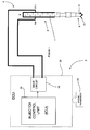
- a known piezoelectric injector 2 and its associated control system 3 is shown schematically in Figure 1.
- the piezoelectric injector 2 includes a piezoelectric actuator 4 that is operable to control the position of an injector valve needle 6 relative to a valve needle seat 8.
- the piezoelectric actuator 4 includes a stack 7 of piezoelectric elements that expands and contacts in dependence on the voltage across the stack 7.
- the axial position, or 'lift', of the valve needle 6 is controlled by applying a variable voltage 'V' to the piezoelectric actuator 4.
- the variable voltage would be applied to the actuator by connecting a power supply plug to the terminals of the injector.
- valve needle 6 By application of an appropriate voltage across the actuator, the valve needle 6 is caused either to disengage the valve seat 8, in which case fuel is delivered into an associated combustion chamber (not shown) through a set of nozzle outlets 10, or is caused to engage the valve seat 8, in which case fuel delivery through the outlets 10 is prevented.
- an injector of this type is described in applicant's European Patent No. EP 0955901B .
- Such fuel injectors may be employed in compression-ignition (diesel) engines or spark ignition (petrol) engines.
- piezoelectric injectors are adept at delivering precise quantities of fuel with accurate timing, they also have associated disadvantages. For example, during use, a piezoelectric injector emits vibrations due to the frequency of the drive voltage that is applied to the piezoelectric actuator. The vibrations travel down the injector, or through an injector positioning/clamping arrangement, and are transmitted to the engine. The engine accentuates certain frequencies such that at least a portion of the vibrations can be detected by the human ear.
- the emitted noise of the injectors is drowned out by the combustion noise of the engine.
- the audible injector noise is apparent.
- the detectable noise contributes to the overall noise/vibration/harshness (NVH) characteristics of the vehicle.
- NVH characteristics are a significant factor in successful vehicle design since it influences the buying decision of the consumer. It is therefore desirable to reduce the amount of noise emitted by the injector in an effort to reduce the overall level of noise perceived by the user of the vehicle.
- the invention provides a method of operating an injector drive circuit for an injector arrangement including at least one piezoelectric injector having an injector voltage, the injector drive circuit being operable to apply an activating voltage to the injector to initiate an injection event and a deactivating voltage to the injector to terminate an injection event.
- the method comprises activating injector select means to select a first injector for injection, activating a first switch means to apply the activating voltage to the injector such that the injector voltage transitions from a first voltage level to a second voltage level, activating a second switch means to apply the deactivating voltage to the injector such that the injector voltage transitions from the second voltage level to the first voltage level and, maintaining the activation state of the injector select means for a predetermined period of time after the injector transitions to the first voltage level.
- the invention differs from known methods of operating piezoelectric fuel injectors in that the injector select means is kept in an activated state for an extended period of time. This is in contrast to known methods in which the injector select means is deactivated after the injector voltage has transitioned from the first voltage level to the second voltage level.
- the invention has the advantage of reducing the voltage oscillation of the injector thus reducing noise emitted therefrom.
- the method of the invention is applicable to de-energise-to-inject injectors and also energise-to-inject injectors.
- the activation voltage and the deactivation voltage are applied in a pulse width modulated manner so as to result in a predetermined average current flow through the injector.
- the method includes reactivating the first switch means after the injector voltage has transitioned from the second voltage level to the first voltage level, following which the first switch means is deactivated after a predetermined time period.
- both positive and negative components of injector voltage oscillation are attenuated which improves the reduction of injector noise.
- the first switch means and the injector select means are deactivated substantially at the same time.
- the predetermined time period corresponds to a voltage oscillation time period of the injector.
- the injector arrangement comprises two or more injectors, and the method further includes activating a second injector select means after the injector voltage has transitioned from the second voltage level to the first voltage level.
- the second injector select means may be deactivated after a predetermined period.
- the second injector select switch is deactivated substantially simultaneously with the first injector select switch.
- a computer program product comprising at least one computer program software portion which, when executed in an executing environment, is operable to implement the method of the invention as described above.
- a microcomputer provided with a data storage medium according to the third aspect of the invention.
- Figure 1 is a schematic representation of a known piezoelectric injector 2 and its associated control system.
- the piezoelectric injector 2 is controlled by an injector control unit 20 (hereinafter 'ICU') that forms an integral part of an engine control unit 22 (ECU).
- the ECU 22 monitors a plurality of engine parameters 24 and calculates an engine power requirement signal (not shown) which is input to the ICU 20.
- the ICU 20 calculates a required injection event sequence to provide the required power for the engine and operates an injector drive circuit 26 accordingly.
- the injector drive circuit is also shown as integral to the ECU 22, although it should be appreciated that this is not essential to the invention.
- the injector drive circuit 26 causes the differential voltage between the high and low voltage terminals of the injector, V 1 and V 2 , to transition from a high voltage (typically 200 V) at which no fuel delivery occurs, to a relatively low voltage (typically -55 V), which reduces the actuator voltage and therefore initiates fuel delivery.
- An injector responsive to this drive waveform is referred to as a 'de-energise to inject' injector and is operable to deliver one or more injections of fuel within a single injection event.
- the injection event may include one or more so-called 'pre-' or 'pilot' injections, a main injection, and one or more 'post' injections. In general, several such injections within a single injection event are preferred to increase combustion efficiency of the engine.
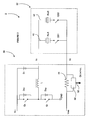
- the drive circuit 26 includes an injector charge/discharge switching circuit 30 (hereinafter 'switching circuit') that is connected to an injector bank circuit 32 so as to control the voltage applied to a high side voltage input V and a low side voltage input V2 of the bank circuit 32.
- an injector charge/discharge switching circuit 30 hereinafter 'switching circuit'
- the injector bank circuit 32 includes first and second branches 40, 42 both of which are connected in parallel between the high and low side voltage inputs V1 and V2.
- Each branch 40, 42 includes a respective injector INJ1, INJ2 and injector select switch QS1, QS2 by which means either one of the injectors can be selected for operation, as will be described later.
- the piezoelectric actuator 4 of each injector 2 is considered electrically equivalent to a capacitor, the voltage difference between V1 and V2 determining the amount of electrical charge stored by the actuator and, thus, the position of the injector valve needle 8.
- the switching circuit 30 includes three input voltage rails: a high voltage rail V HI (typically 255 V) a mid voltage rail V MID (typically 55 V) and a ground connection GND.
- the switching circuit 30 is operable to connect the high side voltage input V1 of the injector bank circuit to either the high voltage rail V HI or the ground connection GND by means of first and second switches Q1, Q2 to which the injector bank 32 is connected, through an inductor L.
- the switching circuit 30 is also provided with a diode D1 that connects the high side voltage input V1 of the bank circuit 32 to the high voltage rail V HI .
- the diode D1 is oriented to permit current to flow from the high side input V1 of the bank circuit 32 to the high voltage rail V HI but to prevent current flow from the high voltage rail V HI to the high side voltage input V1 of the bank circuit 32.
- the first switch Q1 when activated, connects the high side input V1 of the selected injector to the ground connection GND via the inductor L. Therefore, charge from the injector is permitted to flow from the selected injector, through the inductor L and switch Q1 to the ground connection GND, thereby serving to discharge the selected injector during an injector discharge phase.
- the first switch will therefore be referred to as the 'discharge select switch' Q1.
- a diode D Q1 is connected across the second switch Q2 and is oriented to permit current to flow from the inductor L to the high voltage rail V HI when the discharge select switch Q1 is deactivated, thus guarding against voltage peaks across the inductor L.
- the second switch Q2 when activated, connects the high side input V1 of the selected injector to the high voltage rail V HI via the inductor L.
- activating the second switch Q2 causes charge to flow from the high voltage rail V HI , through the second switch Q2 and the inductor L, and into the injector, during an injector charge phase, until an equilibrium voltage is reached (the voltage due to charge stored by the actuator equals the voltage difference between the high side and low side voltage inputs V1, V2).
- the second switch will be referred to as the 'charge select switch' Q2.
- a diode D Q2 is connected across the discharge select switch Q1 and is oriented to permit current to flow from the ground connection GND through the inductor L to the high side input V1 when the charge select switch Q2 is deactivated, thus guarding against voltage peaks across the inductor L.
- the inductor L constitutes a bidirectional current path since current flows in a first direction through the inductor L during the discharge phase and in a second, opposite direction during the injector charge phase.
- the low side voltage input V2 of the injector bank circuit 32 is connected to the mid voltage rail V MID via a voltage sense resistor 44.
- a current sensing and comparator means 50 (hereinafter 'comparator module') is connected in parallel with the sense resistor 44 and is operable to monitor the current flowing therethrough.
- the comparator module 50 outputs a control signal 52 (hereafter Q CONTROL ) that controls the activation status of the discharge select switch Q1 and the charge select switch Q2 so as to regulate the peak current flowing out of, or into, the operating injector.
- the comparator module 50 controls the activation status of the switches Q1 and Q2 to 'chop' the injector current between maximum and minimum current limits and achieve a predetermined average charge or discharge current.
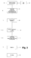
- the injector drive circuit 26 is at equilibrium, that is to say both injectors INJ1 and INJ2 are fully charged such that no fuel injection is taking place. In these circumstances, the ICU 20 is in a wait state, indicated at step 100, awaiting an injection command signal from the ECU 22.
- the ICU 20 selects the injector that it is required to operate at step 104.
- the selected injector is the first injector, INJ1.
- the ICU 20 initiates the discharge phase by enabling the discharge select switch Q1 so as to cause the injector INJ1 to discharge.
- a predetermined average discharge current through the injector is ensured by the operation of the comparator module 50 outputting the Q CONTROL signal between T 0 and T 1 to repeatedly deactivate and reactivate the discharge select switch Q1 such that the current remains within predetermined limits. It should be appreciated that the current flowing out of the injector INJ1 is therefore controlled in a pulse width modulated (PWM) manner.
- PWM pulse width modulated
- the ICU 20 applies the predetermined average discharge current to the stack for a period of time (from T 0 to T 1 ) sufficient to transfer a predetermined amount of charge off of the stack (it should be appreciated that the discharge phase timings are read from a timing map by the ICU 20).
- the ICU 20 deactivates the first injector select switch QS1 and disables the discharge select switch Q1, thus terminating the control signal Q CONTROL , to prevent the injector discharging further.
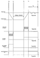
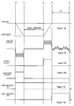
- the stack voltage drops from a charged voltage level V CHARGE to a discharged voltage level V DISCHARGE , as indicated in Figure 4d.
- the ICU 20 maintains the injector INJ1 at the discharged voltage level V DISCHARGE for a predetermined dwell period, T 1 to T 2 , such that the injector valve needle 8 is held open to perform an injection.
- the ICU 20 enables the charge select switch Q2 in order to start the injector charge phase so as to terminate injection.
- the high side voltage input V1 of the injector bank circuit 32 is connected to the high voltage rail V HI and charge begins to transfer into the injector INJ1.
- the comparator module 50 monitors the current flowing through the sense resistor 44 and controls the activation status of the charge select switch Q2, via the control signal Q CONTROL to ensure a predetermined average charging current level.
- the ICU 20 applies the predetermined average charging current to the stack for a period of time sufficient to transfer a predetermined amount of charge onto the stack.
- the ICU 20 disables the charge select switch Q2 and returns to the waiting step 100 ready for initiation of another injection event.
- the above described method achieves an injection event adequately by discharging and then recharging the actuator, it has been observed that after the charge select switch Q2 has been disabled at time T 3 (step 112) the measured voltage across the injector fluctuates for a period of time, as indicated in Figure 4a as an 'oscillation period' Tp.
- the forces applied to the stack for example mechanical vibrations and pressure wave effects oscillate which causes a positive voltage oscillation followed by a negative voltage oscillation that eventually reduce in magnitude at which point the actuator displacement is at rest substantially at the target displacement.
- the injector drive circuit 26 is in equilibrium such that both injectors INJ1 and INJ2 are fully charged. As a result, no fuel injection occurs and the ICU 20 is in a wait state, at step 200, awaiting an injection command signal from the ECU 22.
- the ICU 20 receives an injector command signal and, at step 204, selects the injector that is required to operate by activating the appropriate injector select switch, in this case the first injector select switch QS1 corresponding to the first injector INJ1 of the bank circuit 32.
- the ICU 20 enables the discharge select switch Q1 in order to initiate the discharge phase on INJ1. Charge therefore begins to flow from the injector INJ1, through the inductor L and the discharge select switch Q1 to the ground connection GND.
- the ICU 20 applies a predetermined average discharge current for a predetermined time period (between time periods T 0 and T 1 ) sufficient to transfer a predetermined amount of charge off of the stack.
- the comparator module 50 is operable to monitor the current flow through the sense resistor 44 and repeatedly de-activate and activate the discharge select switch Q1 via the control signal Q CONTROL . It should be appreciated that in this embodiment the injector INJ1 is controlled, initially, in a like manner to that described above with reference to Figure 3 and Figures 4a to 4e.
- the ICU 20 disables the discharge select switch Q1 such that the stack voltage resides at a discharged voltage level V DISCHARGE .
- the ICU 20 maintains the injector select switch QS1 in an activated state until after the injector INJ1 has been recharged, as is described below.
- the ICU 20 maintains the injector INJ1 at a discharged voltage level V DISCHARGE for a dwell period between time periods T 1 and T 2 , such that the injector valve needle 8 is held open so as to perform an injection.
- the ICU 20 enables the charge select switch Q2 so as to start the injector charge phase and thus end injection by closing the injector valve needle 8.
- the high side voltage input V1 of the injector bank circuit 32 is connected to the high voltage rail V HI such that charge begins to transfer through the charge select switch Q2 and the inductor L, into the injector INJ1.
- the comparator module 50 monitors the current through the sense resistor 44 and controls the activation status of the charge select switch Q2, via Q2 CONTROL , in a PWM manner so as to ensure a predetermined average charge current level.
- the ICU 20 applies the predetermined average charging current to the stack for a period of time sufficient to transfer a predetermined amount of charge onto the stack.
- the ICU 20 disables the charge select switch Q2.
- the injector select switch QS1 in still in an activated state, which has the effect of clamping the high side voltage input V1 of the bank circuit 32 to the high voltage rail V HI .
- the benefit of this is that the voltage across the injector INJ1 does not overshoot or oscillate so the positive component of the voltage oscillation observed in Figure 3 is suppressed.
- the ICU 20 maintains the injector select switch QS1 in an activated state, at step 214, for a predetermined period T, shown on Figure 6d as between T 3 and T 4 .
- the predetermined period T is calculated to the time period required for the voltage oscillation to have reduced, or damped, to an acceptable level.
- the length of the predetermined period T may be influenced by the requirement for a commanded injection event on the second injector INJ2 in the bank circuit 32.
- the ICU 20 Following deactivation of the injector select switch QS1, the ICU 20 returns to the wait state 200, ready to receive another injection command.
- the ICU 20 receives an injector command signal and, at step 304, selects the injector to be operated, in this case the first injector INJI, by activating the appropriate injector select switch QS1.
- the ICU 20 enables the discharge select switch Q1 to initiate the discharge phase such that charge is transferred from the injector INJ1, through the inductor L and the discharge select switch Q1 to the ground connection GND.
- the comparator module 50 is operable to monitor the current flow through the sense resistor 44 and repeatedly de-activate and activate the discharge select switch Q1 via the control signal Q CONTROL .
- the ICU 20 applies the predetermined average discharge current to the stack for a period of time sufficient to transfer a predetermined amount of charge off of the stack.
- the ICU 20 deactivates the discharge select switch Q1. As in the previous embodiment of the invention, the ICU 20 maintains the injector select switch QS1 in an activated state until after the injector has been recharged.
- the ICU 20 maintains the injector INJ1 in a discharged state for a dwell period, between T 1 and T 2 , during which time the injector valve needle 8 is held open to perform an injection.
- the ICU 20 enables the charge select switch Q2 to initiate the injector charge phase and, thus, end the injection event by closing the injector valve needle 8.
- the high side voltage input V1 of the injector bank circuit 32 is connected to the high voltage rail V HI such that charge begins to transfer to the injector INJ1, though the charge select switch Q2 and the inductor L.
- the comparator module 50 monitors the current and controls the activation status of the charge select switch Q2 via the control signal Q CONTROL so as to ensure a predetermined average charge current level.
- the ICU 20 applies the predetermined average charging current to the stack for a period of time sufficient to transfer a predetermined amount of charge onto the stack.
- the ICU 20 disables the charge select switch Q2.
- the injector drive circuit 26 is substantially the same as in the previous embodiment.
- the ICU 20 rather than deactivating the charge select switch Q2 at this point (as in the first embodiment of the invention), the ICU 20 maintains the activation state for a predetermined period T, as indicated in Figure 8a.
- the injector select switch QS1 is also in an activated state at this point.
- the ICU 20 deactivates the charge select switch Q2 and the injector select switch QS1 substantially simultaneously.
- the high side voltage input terminal V1 is effectively clamped to the high voltage rail V HI by means of the activated injector select switch QS1. Therefore, as the actuator displacement overshoots at the end of the charging phase, a relatively small amount of current will flow out of the injector to V HI ⁇
- this embodiment provides a means to further reduce the voltage oscillation by reducing the extent of the negative voltage component. Since the charge select switch Q2 remains activated after the charging phase, charge is permitted to flow from the high voltage rail V HI , through the charge select switch Q2 and the inductor L, into the injector INJ1.
- the ICU 20 activates the first injector select switch QS1 to select the first injector INJ1 for operation.
- the ICU 20 enables the discharge select switch Q1 to initiate the discharge phase such that charge is transferred from the injector INJ1 through the inductor L and the discharge select switch Q1 to the ground connection GND.
- the ICU 20 applies a predetermined average discharge current for a predetermined period of time (from T 0 to T 1 ) sufficient to transfer a predetermined amount of charge off of the stack.
- the comparator module 50 is operable between time periods T 0 and T 1 to monitor the current flow through the sensor resistor 44 and repeatedly de-activate and activate the discharge select switch Q1 via the control signal Q CONTROL .
- the ICU 20 disables the discharge select switch Q1 such that the stack voltage resides at a discharged voltage level V DISCHARCE .
- the ICU 20 maintains the injector select switch QS1 in an activated state for a predetermined period of time after the injector has been recharged, as is described below.
- the ICU 20 maintains the injector INJ1 at the discharged voltage level V DISCHARGE for a predetermined dwell period, between time periods T 1 and T 2 , during which time the injector valve needle 8 is held open to perform an injection.
- the ICU 20 enables the charge select switch Q2 so as to initiate the injector charge phase and thus end the injection event.
- the high side voltage input V1 of the injector bank circuit 32 is connected to the high voltage rail V HI and charge begins to transfer through the charge select switch Q2 and the inductor L, and into the injector INJ1.
- the comparator module 50 monitors the current and controls the activation status of the charge select switch Q2, via the control signal Q CONTROL , in a PWM manner so as to ensure a predetermined average current level.
- the ICU 20 applies the predetermined average charging current to the stack for a period of time sufficient to transfer a predetermined amount of charge onto the stack.
- the ICU 20 disables the charge select switch Q2.
- the ICU 20 activates the second injector select switch QS2 for a predetermined period of time T. After the predetermined time period T following the injector charge phase, between T 3 and T 4 , the ICU 20 deactivates both injector select switches QS1, QS2 substantially simultaneously.
- This embodiment provides the advantage that the overshoot and undershoot components of the injector voltage during the oscillation phase are substantially eliminated.
- the high side voltage input V1 of the first injector INJ1 is clamped to the high voltage rail V HI .
- the injector select switch QS2 for the second injector INJ2 is activated, current is permitted to circulate through the resistive network of the injector bank 30 that connects the first and second injectors INJ1, INJ2.
- energy is dissipated through the circuit impedance of the injector bank circuit 32. The dissipation of actuator energy acts to damp the displacement of the actuator and this has the observed result of reducing the high frequency noise contribution from the injectors.
- the ICU 20 has been described as integral to the ECU 22, this need not be the case and the ICU 20 may be arranged to be separated physically from the ECU 22.
Landscapes
- Engineering & Computer Science (AREA)
- Chemical & Material Sciences (AREA)
- Combustion & Propulsion (AREA)
- Mechanical Engineering (AREA)
- General Engineering & Computer Science (AREA)
- Fuel-Injection Apparatus (AREA)
- Electrical Control Of Air Or Fuel Supplied To Internal-Combustion Engine (AREA)
Applications Claiming Priority (1)
| Application Number | Priority Date | Filing Date | Title |
|---|---|---|---|
| GBGB0610233.9A GB0610233D0 (en) | 2006-05-23 | 2006-05-23 | A method of operating a fuel injector |
Publications (1)
| Publication Number | Publication Date |
|---|---|
| EP1860308A1 true EP1860308A1 (fr) | 2007-11-28 |
Family
ID=36687581
Family Applications (1)
| Application Number | Title | Priority Date | Filing Date |
|---|---|---|---|
| EP06254141A Withdrawn EP1860308A1 (fr) | 2006-05-23 | 2006-08-08 | Procédé de commande d'un injecteur à carburant |
Country Status (2)
| Country | Link |
|---|---|
| EP (1) | EP1860308A1 (fr) |
| GB (1) | GB0610233D0 (fr) |
Cited By (1)
| Publication number | Priority date | Publication date | Assignee | Title |
|---|---|---|---|---|
| FR3055991A1 (fr) * | 2016-09-14 | 2018-03-16 | Continental Automotive France | Procede de detection de defaillances |
Citations (2)
| Publication number | Priority date | Publication date | Assignee | Title |
|---|---|---|---|---|
| EP1400677A2 (fr) * | 2002-09-23 | 2004-03-24 | Delphi Technologies, Inc. | Système d'injection |
| WO2005028836A1 (fr) * | 2003-09-23 | 2005-03-31 | Delphi Technologies, Inc. | Circuit d'attaque pour agencement d'injecteur |
-
2006
- 2006-05-23 GB GBGB0610233.9A patent/GB0610233D0/en not_active Ceased
- 2006-08-08 EP EP06254141A patent/EP1860308A1/fr not_active Withdrawn
Patent Citations (3)
| Publication number | Priority date | Publication date | Assignee | Title |
|---|---|---|---|---|
| EP1400677A2 (fr) * | 2002-09-23 | 2004-03-24 | Delphi Technologies, Inc. | Système d'injection |
| EP1400676A2 (fr) * | 2002-09-23 | 2004-03-24 | Delphi Technologies, Inc. | Circuit de commande pour injecteur de carburant |
| WO2005028836A1 (fr) * | 2003-09-23 | 2005-03-31 | Delphi Technologies, Inc. | Circuit d'attaque pour agencement d'injecteur |
Cited By (5)
| Publication number | Priority date | Publication date | Assignee | Title |
|---|---|---|---|---|
| FR3055991A1 (fr) * | 2016-09-14 | 2018-03-16 | Continental Automotive France | Procede de detection de defaillances |
| WO2018050994A1 (fr) * | 2016-09-14 | 2018-03-22 | Continental Automotive France | Procédé de détection de défaillances |
| CN109716300A (zh) * | 2016-09-14 | 2019-05-03 | 法国大陆汽车公司 | 故障检测方法 |
| US11003520B2 (en) | 2016-09-14 | 2021-05-11 | Continental Automotive France | Method of detecting failures |
| CN109716300B (zh) * | 2016-09-14 | 2022-07-15 | 法国大陆汽车公司 | 故障检测方法 |
Also Published As
| Publication number | Publication date |
|---|---|
| GB0610233D0 (en) | 2006-07-05 |
Similar Documents
| Publication | Publication Date | Title |
|---|---|---|
| EP1860310B1 (fr) | Procédé pour faire fonctionner un injecteur de carburant | |
| US4922878A (en) | Method and apparatus for controlling a solenoid operated fuel injector | |
| US6571773B1 (en) | Fuel injector and internal combustion engine | |
| EP2236797B1 (fr) | Verbrennungsmotorsteuerung | |
| US8649151B2 (en) | Injector drive circuit | |
| EP1860309B1 (fr) | Améliorations relatives à la commande des injecteurs de carburant | |
| JP4148127B2 (ja) | 燃料噴射装置 | |
| JP4372722B2 (ja) | 燃料噴射装置 | |
| JP2001221121A (ja) | 電磁式燃料噴射装置及びこれを搭載した内燃機関 | |
| US10648419B2 (en) | Fuel injection control device and fuel injection system | |
| JP5356767B2 (ja) | 燃料噴射装置を制御する方法 | |
| EP1400677B1 (fr) | Système d'injection | |
| EP1956221B1 (fr) | Procédé de fonctionnement d'un actionneur piézoélectrique | |
| EP1927742A1 (fr) | Procédé de fonctionnement d'un dispositif piézoélectrique | |
| EP1860308A1 (fr) | Procédé de commande d'un injecteur à carburant | |
| EP1860311B1 (fr) | Contrôleur pour injecteur de carburant et procédé de fonctionnement d'un injecteur de carburant | |
| JP2006144588A (ja) | ピエゾインジェクタの駆動装置 | |
| EP2128415A1 (fr) | Améliorations d'une commande d'injecteur de carburant | |
| JP2000303882A (ja) | 燃料噴射制御装置 | |
| CN111527296B (zh) | 用于调节机动车辆的发动机的控制计算机的dc-dc电压转换器的输出电压的方法 | |
| JP2002295293A (ja) | 燃料噴射装置 | |
| EP1927741A1 (fr) | Procédé de commande d'un dispositif piézoélectrique | |
| JP4803016B2 (ja) | 燃料噴射制御装置 | |
| KR20020032652A (ko) | 연료분사 제어장치 |
Legal Events
| Date | Code | Title | Description |
|---|---|---|---|
| PUAI | Public reference made under article 153(3) epc to a published international application that has entered the european phase |
Free format text: ORIGINAL CODE: 0009012 |
|
| AK | Designated contracting states |
Kind code of ref document: A1 Designated state(s): AT BE BG CH CY CZ DE DK EE ES FI FR GB GR HU IE IS IT LI LT LU LV MC NL PL PT RO SE SI SK TR |
|
| AX | Request for extension of the european patent |
Extension state: AL BA HR MK YU |
|
| AKX | Designation fees paid | ||
| REG | Reference to a national code |
Ref country code: DE Ref legal event code: 8566 |
|
| STAA | Information on the status of an ep patent application or granted ep patent |
Free format text: STATUS: THE APPLICATION IS DEEMED TO BE WITHDRAWN |
|
| 18D | Application deemed to be withdrawn |
Effective date: 20080529 |