EP1860263A2 - Hinge assembly - Google Patents
Hinge assembly Download PDFInfo
- Publication number
- EP1860263A2 EP1860263A2 EP07270024A EP07270024A EP1860263A2 EP 1860263 A2 EP1860263 A2 EP 1860263A2 EP 07270024 A EP07270024 A EP 07270024A EP 07270024 A EP07270024 A EP 07270024A EP 1860263 A2 EP1860263 A2 EP 1860263A2
- Authority
- EP
- European Patent Office
- Prior art keywords
- cam
- hinge
- abutment surface
- closure
- rotational axis
- Prior art date
- Legal status (The legal status is an assumption and is not a legal conclusion. Google has not performed a legal analysis and makes no representation as to the accuracy of the status listed.)
- Granted
Links
Images
Classifications
-
- E—FIXED CONSTRUCTIONS
- E05—LOCKS; KEYS; WINDOW OR DOOR FITTINGS; SAFES
- E05D—HINGES OR SUSPENSION DEVICES FOR DOORS, WINDOWS OR WINGS
- E05D3/00—Hinges with pins
- E05D3/02—Hinges with pins with one pin
- E05D3/022—Hinges with pins with one pin allowing an additional lateral movement, e.g. for sealing
-
- A—HUMAN NECESSITIES
- A47—FURNITURE; DOMESTIC ARTICLES OR APPLIANCES; COFFEE MILLS; SPICE MILLS; SUCTION CLEANERS IN GENERAL
- A47L—DOMESTIC WASHING OR CLEANING; SUCTION CLEANERS IN GENERAL
- A47L9/00—Details or accessories of suction cleaners, e.g. mechanical means for controlling the suction or for effecting pulsating action; Storing devices specially adapted to suction cleaners or parts thereof; Carrying-vehicles specially adapted for suction cleaners
-
- E—FIXED CONSTRUCTIONS
- E05—LOCKS; KEYS; WINDOW OR DOOR FITTINGS; SAFES
- E05Y—INDEXING SCHEME RELATING TO HINGES OR OTHER SUSPENSION DEVICES FOR DOORS, WINDOWS OR WINGS AND DEVICES FOR MOVING WINGS INTO OPEN OR CLOSED POSITION, CHECKS FOR WINGS AND WING FITTINGS NOT OTHERWISE PROVIDED FOR, CONCERNED WITH THE FUNCTIONING OF THE WING
- E05Y2201/00—Constructional elements; Accessories therefore
- E05Y2201/40—Motors; Magnets; Springs; Weights; Accessories therefore
- E05Y2201/404—Motors; Magnets; Springs; Weights; Accessories therefore characterised by the function
- E05Y2201/422—Motors; Magnets; Springs; Weights; Accessories therefore characterised by the function for opening
-
- E—FIXED CONSTRUCTIONS
- E05—LOCKS; KEYS; WINDOW OR DOOR FITTINGS; SAFES
- E05Y—INDEXING SCHEME RELATING TO HINGES OR OTHER SUSPENSION DEVICES FOR DOORS, WINDOWS OR WINGS AND DEVICES FOR MOVING WINGS INTO OPEN OR CLOSED POSITION, CHECKS FOR WINGS AND WING FITTINGS NOT OTHERWISE PROVIDED FOR, CONCERNED WITH THE FUNCTIONING OF THE WING
- E05Y2201/00—Constructional elements; Accessories therefore
- E05Y2201/60—Suspension or transmission members; Accessories therefore
- E05Y2201/622—Suspension or transmission members elements
- E05Y2201/638—Cams; Ramps
-
- E—FIXED CONSTRUCTIONS
- E05—LOCKS; KEYS; WINDOW OR DOOR FITTINGS; SAFES
- E05Y—INDEXING SCHEME RELATING TO HINGES OR OTHER SUSPENSION DEVICES FOR DOORS, WINDOWS OR WINGS AND DEVICES FOR MOVING WINGS INTO OPEN OR CLOSED POSITION, CHECKS FOR WINGS AND WING FITTINGS NOT OTHERWISE PROVIDED FOR, CONCERNED WITH THE FUNCTIONING OF THE WING
- E05Y2900/00—Application of doors, windows, wings or fittings thereof
- E05Y2900/30—Application of doors, windows, wings or fittings thereof for domestic appliances
Definitions
- This invention relates to a hinge assembly and more particularly but not solely to a hinge for a closure of a vacuum cleaner or other device.
- Vacuum cleaners generally comprise an external housing, which is often provided with one or more closures that can be opened to reveal dust separation devices, such as dust bags, filters or cyclone units.
- the closure must be easy and convenient to open and close, in order to facilitate replacement or emptying of the dust separation device.
- the closure must also be capable of wide opening, so that a voluminous full dust bag can be easily removed from the cleaner.
- vacuum cleaners having closures, which can be opened to reveal storage compartments for cleaning tools and the like. It is desirable, for aesthetic reasons, for any such closures to be mounted flush with the housing of the cleaner, with their side edges being located in close proximity to the side edges of the surrounding portion of the housing.
- German Patent DE 4419064 discloses an alternative to double-pivot hinges, which comprises a pair of arcuate arms, rigidly attached to the bag chamber closure. The arms are a sliding fit within a pair of arcuate cavities formed in the body of the cleaner. It will be appreciated that such an arrangement imposes restrictions similar to those associated with the double-pivot arms disclosed in European Patent EP 0116870 .
- a hinge assembly comprising a first hinge portion pivotally interconnected to a displaceable second hinge portion for rotation about a rotational axis, an axially projecting cam on said first portion having a cam surface disposed radially outwardly of said rotational axis, and a fixed abutment surface disposed remote from said hinge portions, wherein the cam surface is biased against said abutment surface, the assembly being arranged such that rotation of the first hinge portion about said rotational axis causes said cam to ride over said abutment surface under the applied bias allowing translatory movement of the rotational axis.
- the first and second hinge portions are respectively connected to the closure and chassis thereof.
- the axis of rotation moves away from the body of the cleaner in a controlled manner by the action of the cam, thereby allowing space for the opposite side of the closure to move inwardly without fouling the body of the cleaner.
- the hinge assembly is simple in construction and only makes small demands on space within the vacuum cleaner body.
- the assembly provides the functional attributes of the prior art whilst enabling the rotational axis to be located close to the extremity of the cleaner body, for example at the extreme front of a canister cleaner, without the hinge mechanism encroaching on the internal space of the cleaner.
- a rotational bias is applied between said first and second hinge portions, means being provided for holding the hinge portions against said rotational bias is applied, such that when the holding means is released the rotational bias causes rotation of the first hinge portion about said rotational axis and causes said cam to ride over said abutment surface under the aforementioned applied bias allowing said translatory movement of the rotational axis.
- cam surface is biased against said abutment surface by bias means acting on said displaceable second hinge portion.
- the cam is disposed at a radial distance of 5 to 15 mm away from the axis of rotation.
- the cam is able to move away from the abutment surface against the spring bias in order to help avoid jamming of the assembly, for example when the closure is closed.
- At least a portion of the abutment surface is inclined relative to a plane which extends normal to the direction of the applied bias, so as to control, amplify or otherwise vary the ratio of translatory movement of the rotational axis to the angle of rotation.
- the cam comprises a projection which extends outwardly from said first hinge portion, preferably in a direction which extends axially of the axis of rotation.
- a detent is provided on the cam to retain the hinge in a particular angular configuration.
- the detent may comprise a planar region formed in an arcuate camming surface of the cam.
- a device comprising a closure having a first hinge portion and a body having a second hinge portion displaceably mounted thereon, the first portion being pivotally connected to the second portion for rotation of the closure about a rotational axis relative to the body, the device further comprising an axially projecting cam on said first portion having a cam surface disposed radially outwardly of said rotational axis, and a fixed abutment surface disposed remote from said hinge portions, wherein the cam surface is biased against said abutment surface, the device being arranged such that rotation of the first hinge portion about said rotational axis causes said cam to ride over said abutment surface under the applied bias allowing translatory movement of the rotational axis of the closure.
- a rotational bias is applied between said first and second hinge portions, means being provided for holding the hinge portions in a relative position in which said rotational bias is applied, such that when the holding means is released the rotational bias causes rotation of the first hinge portion about said rotational axis and causes said cam to ride over said abutment surface under the aforementioned applied bias allowing said translatory movement of the rotational axis.
- the holding means comprises a catch which retains the closure in a closed on the body, the rotational bias preferably being applied to the closure in an opening direction such that the translatory movement occurs as the closure opens under the applied rotational bias.
- the second portion is slidably mounted to the body of the cleaner.
- cam surface is biased against said abutment surface by bias means acting on said displaceable second hinge portion.
- cam surface is biased against said abutment surface in a direction which extends substantially normal to the plane of the closure when the latter is in its closed position.
- the cam surface is biased against said abutment surface in a direction which extends outwardly of the body of the device.
- the cam is arranged to rotate away from said closure when the closure is opened.
- the body portion 10 of a vacuum cleaner comprising an external housing of plastics material.
- a compartment 11 is formed inside the body 10 for receiving a dust bag (not shown) or other dust collection device, such as a porous dust box or cyclone unit.
- a closure 12 is provided in the upper surface of the body 10 and can be opened to allow the user to access the compartment 11, for example when changing or emptying the dust bag or other dust separation device.
- the closure 12 is a flush fit with the housing of the body and the side edges thereof conform to the shape of the surrounding portions of the housing.
- the closure 12 is hinged to the body 10 of the cleaner, adjacent the front edge thereof, for rotation about a horizontal axis P.
- a spring biases the closure 12 about the axis P into its open position.
- a catch(not shown) is provided for retaining the closure 12 in its closed position against the rotational bias.
- the closure 12 is hinged to the body 10 of the cleaner by way of two depending arms e.g. 13, which extend from respective opposite ends of the lower front edge of the closure 12.
- the lower end of each arm 13 is turned forwardly through 90° and carries an axle 14, which projects outwardly from one side of the arm 13 in a direction which extends transversely of the cleaner and parallel to the plane of the closure 12.
- the axles 14 of the two arms 13 lie on a common axis A-A and are directed in respective opposite directions, transversely of the body 10 of the cleaner.
- the axles 14 engage into apertures formed in respective upstanding posts 15.
- the lower ends of the posts 15 are captively mounted in sockets 19 formed in a chassis of the cleaner, for movement in a direction D, which extends longitudinally of the posts 15.
- the posts 15 are biased upwardly by respective compression springs 16.
- Each arm 13 of the hinge comprises a projecting cam 17, which extends outwardly therefrom in the opposite direction to the axle 14.
- the cams 17 extend along an axis B-B, which extends parallel to the axis A-A of the axles 14, in a position which is offset therefrom by a distance X of between 5 and 15mm.
- the cams 17 are disposed on the forward side of the rotational axis A-A, whereas the closure 12 is disposed substantially on the rearward side of the rotational axis.
- the cams 17 are also positioned at a point which is arranged such that when the closure 12 is closed, their position with respect to the rotational axis A-A is disposed in a direction which extends substantially normal to the direction of movement of the posts 15.
- the axially extending sides of the cams 17 comprise arcuate camming surfaces, which face upwardly and rearwardly of the cleaner. An upwardly facing portion of the camming surfaces are generally planar.
- the cams 17 each extend under an inclined abutment surface 18 formed along the underside of respective side members of the chassis of the vacuum cleaner.
- the abutment surfaces 18 are upwardly inclined from the front to the rear of the cleaner.
- the camming surfaces of the cam 17 are biased upwardly against the abutment surfaces 18 by the action of the springs 16 on the posts 15.
- the rotational axis A-A of the hinge thus rises during opening by a distance L.
- This height rise allows the closure 12 to open through almost 90°, yet avoids fouling of the lower front edge of the closure 12 with the body 10 of the cleaner. Accordingly, the hinge of the present invention avoids the need for an unsightly gap to be provided between the closure 12 and the body 10 of the cleaner.
Abstract
Description
- This invention relates to a hinge assembly and more particularly but not solely to a hinge for a closure of a vacuum cleaner or other device.
- Vacuum cleaners generally comprise an external housing, which is often provided with one or more closures that can be opened to reveal dust separation devices, such as dust bags, filters or cyclone units. The closure must be easy and convenient to open and close, in order to facilitate replacement or emptying of the dust separation device. The closure must also be capable of wide opening, so that a voluminous full dust bag can be easily removed from the cleaner.
- It is also known to provide vacuum cleaners having closures, which can be opened to reveal storage compartments for cleaning tools and the like. It is desirable, for aesthetic reasons, for any such closures to be mounted flush with the housing of the cleaner, with their side edges being located in close proximity to the side edges of the surrounding portion of the housing.
- The need for the closure to conform to the shape of the cleaner housing and to open widely has led to adoption of complex double-axis hinges, whereby the closure is pivotally mounted to a pair of hinge arms, the hinge arms themselves being a pivotally mounted to the body of the cleaner. A hinge arrangement of this type is disclosed in
European Patent EP 0116870 . It will be appreciated that the need to accommodate the hinge arms within the cleaner body makes demands on space within the body and can impose restrictions on the form and location of the bag chamber closure. -
German Patent DE 4419064 discloses an alternative to double-pivot hinges, which comprises a pair of arcuate arms, rigidly attached to the bag chamber closure. The arms are a sliding fit within a pair of arcuate cavities formed in the body of the cleaner. It will be appreciated that such an arrangement imposes restrictions similar to those associated with the double-pivot arms disclosed inEuropean Patent EP 0116870 . - We have now devised a hinge assembly which alleviates the above-mentioned problems.
- In accordance with the present invention, there is provided a hinge assembly comprising a first hinge portion pivotally interconnected to a displaceable second hinge portion for rotation about a rotational axis, an axially projecting cam on said first portion having a cam surface disposed radially outwardly of said rotational axis, and a fixed abutment surface disposed remote from said hinge portions, wherein the cam surface is biased against said abutment surface, the assembly being arranged such that rotation of the first hinge portion about said rotational axis causes said cam to ride over said abutment surface under the applied bias allowing translatory movement of the rotational axis.
- In a vacuum cleaner, the first and second hinge portions are respectively connected to the closure and chassis thereof. As one side of the closure is opened outwardly, the axis of rotation moves away from the body of the cleaner in a controlled manner by the action of the cam, thereby allowing space for the opposite side of the closure to move inwardly without fouling the body of the cleaner.
- The hinge assembly is simple in construction and only makes small demands on space within the vacuum cleaner body. The assembly provides the functional attributes of the prior art whilst enabling the rotational axis to be located close to the extremity of the cleaner body, for example at the extreme front of a canister cleaner, without the hinge mechanism encroaching on the internal space of the cleaner.
- Preferably a rotational bias is applied between said first and second hinge portions, means being provided for holding the hinge portions against said rotational bias is applied, such that when the holding means is released the rotational bias causes rotation of the first hinge portion about said rotational axis and causes said cam to ride over said abutment surface under the aforementioned applied bias allowing said translatory movement of the rotational axis.
- Preferably the cam surface is biased against said abutment surface by bias means acting on said displaceable second hinge portion.
- Preferably the cam is disposed at a radial distance of 5 to 15 mm away from the axis of rotation.
- Preferably the cam is able to move away from the abutment surface against the spring bias in order to help avoid jamming of the assembly, for example when the closure is closed.
- Preferably, at least a portion of the abutment surface is inclined relative to a plane which extends normal to the direction of the applied bias, so as to control, amplify or otherwise vary the ratio of translatory movement of the rotational axis to the angle of rotation.
- Preferably, the cam comprises a projection which extends outwardly from said first hinge portion, preferably in a direction which extends axially of the axis of rotation.
- Preferably, a detent is provided on the cam to retain the hinge in a particular angular configuration. The detent may comprise a planar region formed in an arcuate camming surface of the cam.
- Also in accordance with this invention, there is provided a device comprising a closure having a first hinge portion and a body having a second hinge portion displaceably mounted thereon, the first portion being pivotally connected to the second portion for rotation of the closure about a rotational axis relative to the body, the device further comprising an axially projecting cam on said first portion having a cam surface disposed radially outwardly of said rotational axis, and a fixed abutment surface disposed remote from said hinge portions, wherein the cam surface is biased against said abutment surface, the device being arranged such that rotation of the first hinge portion about said rotational axis causes said cam to ride over said abutment surface under the applied bias allowing translatory movement of the rotational axis of the closure.
- Preferably a rotational bias is applied between said first and second hinge portions, means being provided for holding the hinge portions in a relative position in which said rotational bias is applied, such that when the holding means is released the rotational bias causes rotation of the first hinge portion about said rotational axis and causes said cam to ride over said abutment surface under the aforementioned applied bias allowing said translatory movement of the rotational axis.
- Preferably the holding means comprises a catch which retains the closure in a closed on the body, the rotational bias preferably being applied to the closure in an opening direction such that the translatory movement occurs as the closure opens under the applied rotational bias.
- Preferably the second portion is slidably mounted to the body of the cleaner.
- Preferably the cam surface is biased against said abutment surface by bias means acting on said displaceable second hinge portion.
- Preferably the cam surface is biased against said abutment surface in a direction which extends substantially normal to the plane of the closure when the latter is in its closed position.
- Preferably the cam surface is biased against said abutment surface in a direction which extends outwardly of the body of the device.
- Preferably the cam is arranged to rotate away from said closure when the closure is opened.
- An embodiment of the present invention will now be described by way of an example only and with reference to the accompanying drawings, in which:
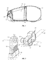
- Figure 1 is a sectional view through a canister vacuum cleaner incorporating a hinge in accordance with the present invention;
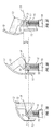
- Figure 2 is an exploded view of the hinge in accordance with the present invention of the vacuum cleaner of Figure 1; and
- Figures 3A - 3C are schematic views illustrating the principle of operation of the hinge of Figure 2.
- Referring to the drawings, there is shown the
body portion 10 of a vacuum cleaner comprising an external housing of plastics material. Acompartment 11 is formed inside thebody 10 for receiving a dust bag (not shown) or other dust collection device, such as a porous dust box or cyclone unit. Aclosure 12 is provided in the upper surface of thebody 10 and can be opened to allow the user to access thecompartment 11, for example when changing or emptying the dust bag or other dust separation device. In order to improve the aesthetic appearance of the cleaner, theclosure 12 is a flush fit with the housing of the body and the side edges thereof conform to the shape of the surrounding portions of the housing. Theclosure 12 is hinged to thebody 10 of the cleaner, adjacent the front edge thereof, for rotation about a horizontal axis P. A spring (not shown) biases theclosure 12 about the axis P into its open position. A catch(not shown) is provided for retaining theclosure 12 in its closed position against the rotational bias. - Referring to Figure 2 of the drawings, the
closure 12 is hinged to thebody 10 of the cleaner by way of two depending arms e.g. 13, which extend from respective opposite ends of the lower front edge of theclosure 12. The lower end of eacharm 13 is turned forwardly through 90° and carries anaxle 14, which projects outwardly from one side of thearm 13 in a direction which extends transversely of the cleaner and parallel to the plane of theclosure 12. Theaxles 14 of the twoarms 13 lie on a common axis A-A and are directed in respective opposite directions, transversely of thebody 10 of the cleaner. - The
axles 14 engage into apertures formed in respectiveupstanding posts 15. The lower ends of theposts 15 are captively mounted insockets 19 formed in a chassis of the cleaner, for movement in a direction D, which extends longitudinally of theposts 15. Theposts 15 are biased upwardly byrespective compression springs 16. - Each
arm 13 of the hinge comprises aprojecting cam 17, which extends outwardly therefrom in the opposite direction to theaxle 14. Thecams 17 extend along an axis B-B, which extends parallel to the axis A-A of theaxles 14, in a position which is offset therefrom by a distance X of between 5 and 15mm. Thecams 17 are disposed on the forward side of the rotational axis A-A, whereas theclosure 12 is disposed substantially on the rearward side of the rotational axis. Thecams 17 are also positioned at a point which is arranged such that when theclosure 12 is closed, their position with respect to the rotational axis A-A is disposed in a direction which extends substantially normal to the direction of movement of theposts 15. The axially extending sides of thecams 17 comprise arcuate camming surfaces, which face upwardly and rearwardly of the cleaner. An upwardly facing portion of the camming surfaces are generally planar. - The
cams 17 each extend under aninclined abutment surface 18 formed along the underside of respective side members of the chassis of the vacuum cleaner. Theabutment surfaces 18 are upwardly inclined from the front to the rear of the cleaner. The camming surfaces of thecam 17 are biased upwardly against theabutment surfaces 18 by the action of thesprings 16 on theposts 15. - Referring to Figure 3A of the drawings, when the
closure 12 is in its closed position, thecams 17 are biased against the lower front end of theirrespective abutment surfaces 18. In this position, the generally planar portions of the camming surfaces are in contact with the respective abutment surfaces 18: these portions act as detents to help keep the closure closed and to provide some feedback feeling to the user that the closure is moving into or out of its closed position. - However, referring to Figures 3B and 3C of the drawings, when catch is released and the
closure 12 moves to its open position under the applied bias, thecams 17 rotate downwardly and rearwardly in a counter clockwise direction, allowing thearms 13 of the hinge to rise under the applied spring bias. During opening, thecams 17 move upwardly along theinclined abutment surfaces 18, thereby increasing the height by which thearms 13 can rise. - It will be appreciated that the rotational axis A-A of the hinge thus rises during opening by a distance L. This height rise allows the
closure 12 to open through almost 90°, yet avoids fouling of the lower front edge of theclosure 12 with thebody 10 of the cleaner. Accordingly, the hinge of the present invention avoids the need for an unsightly gap to be provided between theclosure 12 and thebody 10 of the cleaner.
Claims (16)
- A hinge assembly comprising a first hinge portion pivotally interconnected to a displaceable second hinge portion for rotation about a rotational axis, an axially projecting cam on said first portion having a cam surface disposed radially outwardly of said rotational axis, and a fixed abutment surface disposed remote from said hinge portions, wherein the cam surface is biased against said abutment surface, the assembly being arranged such that rotation of the first hinge portion about said rotational axis causes said cam to ride over said abutment surface under the applied bias allowing translatory movement of the rotational axis.
- A hinge assembly as claimed in claim 1, in which a rotational bias is applied between said first and second hinge portions, means being provided for holding the hinge portions against said rotational bias is applied, such that when the holding means is released the rotational bias causes rotation of the first hinge portion about said rotational axis and causes said cam to ride over said abutment surface under the aforementioned applied bias allowing said translatory movement of the rotational axis.
- A hinge assembly as claimed in claims 1 or 2 , in which the cam surface is biased against said abutment surface by bias means acting on said displaceable second hinge portion.
- A hinge assembly as claimed in any preceding claim, in which the cam is disposed at a radial distance of 5 to 15 mm away from the axis of rotation.
- A hinge assembly as claimed in any preceding claim, in which the cam is able to move away from the abutment surface against the spring.
- A hinge assembly as claimed in any preceding claim, in which at least a portion of the abutment surface is inclined relative to a plane which extends normal to the direction of the applied bias.
- A hinge assembly as claimed in any preceding claim, in which the cam comprises a projection which extends outwardly from said first hinge portion, preferably in a direction which extends axially of the axis of rotation.
- A device comprising a closure having a first hinge portion and a body having a second hinge portion displaceably mounted thereon, the first portion being pivotally connected to the second portion for rotation of the closure about a rotational axis relative to the body, the device further comprising an axially projecting cam on said first portion having a cam surface disposed radially outwardly of said rotational axis, and a fixed abutment surface disposed remote from said hinge portions, wherein the cam surface is biased against said abutment surface, the device being arranged such that rotation of the first hinge portion about said rotational axis causes said cam to ride over said abutment surface under the applied bias allowing translatory movement of the rotational axis of the closure.
- A device as claimed in claim 8, in which a rotational bias is applied between said first and second hinge portions, means being provided for holding the hinge portions against said rotational bias is applied, such that when the holding means is released the rotational bias causes rotation of the first hinge portion about said rotational axis and causes said cam to ride over said abutment surface under the aforementioned applied bias allowing said translatory movement of the rotational axis.
- A device as claimed in claim 9, in which the holding means comprises a catch which retains the closure in a closed on the body, the rotational bias preferably being applied to the closure in an opening direction such that the translatory movement occurs as the closure opens under the applied rotational bias.
- A device as claimed in any of claims 8 to 10, in which the second portion is slidably mounted to the body of the device.
- A device as claimed in any of claims 8 to 11, in which in which the cam surface is biased against said abutment surface by bias means acting on said displaceable second hinge portion.
- A device as claimed in any of claims 8 to 12, in which the cam surface is biased against said abutment surface in a direction which extends substantially normal to the plane of the closure when the latter is in its closed position.
- A device as claimed in any of claims 8 to 13, in which the cam surface is biased against said abutment surface in a direction which extends outwardly of the body of the device.
- A device as claimed in any of claims 8 to 14, in which the cam is arranged to rotate inwardly of the body of the device when the closure is opened.
- A device as claimed in any of claims 8 to 15, comprising dust collection means for filtering dirt and dust from an airflow and means for creating an airflow through the dust collection means.
Applications Claiming Priority (1)
| Application Number | Priority Date | Filing Date | Title |
|---|---|---|---|
| GB0610323A GB2438408B (en) | 2006-05-25 | 2006-05-25 | Hinge Assembly |
Publications (3)
| Publication Number | Publication Date |
|---|---|
| EP1860263A2 true EP1860263A2 (en) | 2007-11-28 |
| EP1860263A3 EP1860263A3 (en) | 2008-06-04 |
| EP1860263B1 EP1860263B1 (en) | 2010-10-06 |
Family
ID=36687664
Family Applications (1)
| Application Number | Title | Priority Date | Filing Date |
|---|---|---|---|
| EP07270024A Not-in-force EP1860263B1 (en) | 2006-05-25 | 2007-05-22 | Device comprising a body, a closure and a hinge |
Country Status (6)
| Country | Link |
|---|---|
| EP (1) | EP1860263B1 (en) |
| CN (1) | CN101077288B (en) |
| AT (1) | ATE483880T1 (en) |
| DE (1) | DE602007009597D1 (en) |
| ES (1) | ES2350010T3 (en) |
| GB (1) | GB2438408B (en) |
Cited By (7)
| Publication number | Priority date | Publication date | Assignee | Title |
|---|---|---|---|---|
| FR2928306A1 (en) * | 2008-03-04 | 2009-09-11 | Coutier Moulage Gen Ind | Motorized or non motorized fuel tank flap for motor vehicle, has shutter articulated on axle such that shutter is opened by displacement of slide, along with rotation of shutter, and spring moving slide to move axle towards exterior of case |
| KR101152837B1 (en) | 2009-11-16 | 2012-06-12 | 장희용 | Hinge by using furniture |
| FR3026630A1 (en) * | 2014-10-06 | 2016-04-08 | Seb Sa | RETURN SPRING FOR MOBILE VACUUM PART |
| WO2016134767A1 (en) * | 2015-02-26 | 2016-09-01 | Huawei Technologies Co., Ltd. | A door and suspension mechanism assembly and an assembly of an elongated housing and a door and suspension mechanism assembly |
| EP3222181A1 (en) * | 2016-03-21 | 2017-09-27 | Miele & Cie. KG | Cyclonic separator for a cyclonic separator vacuum cleaner |
| WO2018006967A1 (en) * | 2016-07-07 | 2018-01-11 | Alfred Kärcher Gmbh & Co. Kg | Cleaning device |
| DE102009035603B4 (en) * | 2009-07-31 | 2018-01-25 | BSH Hausgeräte GmbH | Vacuum cleaner with removable lid |
Families Citing this family (1)
| Publication number | Priority date | Publication date | Assignee | Title |
|---|---|---|---|---|
| JP7043355B2 (en) * | 2018-06-21 | 2022-03-29 | 東芝ライフスタイル株式会社 | Vacuum cleaner |
Citations (5)
| Publication number | Priority date | Publication date | Assignee | Title |
|---|---|---|---|---|
| EP0116870A2 (en) | 1983-01-25 | 1984-08-29 | Progress Elektrogeräte GmbH | Vacuum cleaner |
| EP0124410A1 (en) | 1983-04-14 | 1984-11-07 | Regie Nationale Des Usines Renault | Fuel tank filler cover mechanism for vehicles |
| DE4419064A1 (en) | 1994-05-31 | 1995-12-07 | Siemens Ag | Vacuum cleaner |
| FR2741845A1 (en) | 1995-12-01 | 1997-06-06 | Omegal Sa | System for mounting fuel filler cap, for access to fuel tank of car |
| GB2343915A (en) | 1998-11-23 | 2000-05-24 | Raymond Ralph | Door hinge with moveable pivot axis |
Family Cites Families (4)
| Publication number | Priority date | Publication date | Assignee | Title |
|---|---|---|---|---|
| GB2220701A (en) * | 1989-02-07 | 1990-01-17 | Liu Ping Hsiung | Hinge unit for joining a case and its lid |
| JPH04122336A (en) * | 1990-09-14 | 1992-04-22 | Tokyo Electric Co Ltd | Vacuum cleaner |
| DE4315159A1 (en) * | 1993-05-07 | 1994-11-10 | Lautenschlaeger Mepla Werke | Corner cabinet hinge |
| US6352295B1 (en) * | 1999-04-27 | 2002-03-05 | American Moto Products, Inc. | Fuel door assembly |
-
2006
- 2006-05-25 GB GB0610323A patent/GB2438408B/en not_active Expired - Fee Related
-
2007
- 2007-05-22 AT AT07270024T patent/ATE483880T1/en not_active IP Right Cessation
- 2007-05-22 ES ES07270024T patent/ES2350010T3/en active Active
- 2007-05-22 DE DE602007009597T patent/DE602007009597D1/en active Active
- 2007-05-22 EP EP07270024A patent/EP1860263B1/en not_active Not-in-force
- 2007-05-25 CN CN200710107247.3A patent/CN101077288B/en not_active Expired - Fee Related
Patent Citations (5)
| Publication number | Priority date | Publication date | Assignee | Title |
|---|---|---|---|---|
| EP0116870A2 (en) | 1983-01-25 | 1984-08-29 | Progress Elektrogeräte GmbH | Vacuum cleaner |
| EP0124410A1 (en) | 1983-04-14 | 1984-11-07 | Regie Nationale Des Usines Renault | Fuel tank filler cover mechanism for vehicles |
| DE4419064A1 (en) | 1994-05-31 | 1995-12-07 | Siemens Ag | Vacuum cleaner |
| FR2741845A1 (en) | 1995-12-01 | 1997-06-06 | Omegal Sa | System for mounting fuel filler cap, for access to fuel tank of car |
| GB2343915A (en) | 1998-11-23 | 2000-05-24 | Raymond Ralph | Door hinge with moveable pivot axis |
Cited By (9)
| Publication number | Priority date | Publication date | Assignee | Title |
|---|---|---|---|---|
| FR2928306A1 (en) * | 2008-03-04 | 2009-09-11 | Coutier Moulage Gen Ind | Motorized or non motorized fuel tank flap for motor vehicle, has shutter articulated on axle such that shutter is opened by displacement of slide, along with rotation of shutter, and spring moving slide to move axle towards exterior of case |
| DE102009035603B4 (en) * | 2009-07-31 | 2018-01-25 | BSH Hausgeräte GmbH | Vacuum cleaner with removable lid |
| KR101152837B1 (en) | 2009-11-16 | 2012-06-12 | 장희용 | Hinge by using furniture |
| FR3026630A1 (en) * | 2014-10-06 | 2016-04-08 | Seb Sa | RETURN SPRING FOR MOBILE VACUUM PART |
| EP3005922A1 (en) * | 2014-10-06 | 2016-04-13 | Seb S.A. | Return spring for mobile vacuum cleaner part |
| WO2016134767A1 (en) * | 2015-02-26 | 2016-09-01 | Huawei Technologies Co., Ltd. | A door and suspension mechanism assembly and an assembly of an elongated housing and a door and suspension mechanism assembly |
| US10526831B2 (en) | 2015-02-26 | 2020-01-07 | Huawei Technologies Co., Ltd. | Door and suspension mechanism assembly and an assembly of an elongated housing and a door and suspension mechanism assembly |
| EP3222181A1 (en) * | 2016-03-21 | 2017-09-27 | Miele & Cie. KG | Cyclonic separator for a cyclonic separator vacuum cleaner |
| WO2018006967A1 (en) * | 2016-07-07 | 2018-01-11 | Alfred Kärcher Gmbh & Co. Kg | Cleaning device |
Also Published As
| Publication number | Publication date |
|---|---|
| GB2438408A (en) | 2007-11-28 |
| ES2350010T3 (en) | 2011-01-14 |
| GB2438408B (en) | 2010-03-24 |
| CN101077288B (en) | 2013-06-12 |
| DE602007009597D1 (en) | 2010-11-18 |
| CN101077288A (en) | 2007-11-28 |
| GB0610323D0 (en) | 2006-07-05 |
| ATE483880T1 (en) | 2010-10-15 |
| EP1860263A3 (en) | 2008-06-04 |
| EP1860263B1 (en) | 2010-10-06 |
Similar Documents
| Publication | Publication Date | Title |
|---|---|---|
| EP1860263B1 (en) | Device comprising a body, a closure and a hinge | |
| USD534422S1 (en) | Container with rotating lid | |
| USD545024S1 (en) | Garbage can with step opening lid | |
| CN100382993C (en) | Lid operating device and storage device using the same | |
| CN100374320C (en) | Operating mechanism for reciprocating component | |
| USD522803S1 (en) | Waffle iron | |
| US20050022335A1 (en) | Vacuum cleaner with a dust collection chamber closeable by a lid | |
| USD493617S1 (en) | Hinged lid container | |
| USD538031S1 (en) | Case for housing medication contained within a flexible container | |
| USD535484S1 (en) | Chair | |
| USD519312S1 (en) | Container for compact disc | |
| US20060242787A1 (en) | Vacuum bag mounting assembly | |
| US9706887B2 (en) | Cleaner-head for a vacuum cleaner | |
| JP6576840B2 (en) | Cup holder | |
| USD545185S1 (en) | Container | |
| JP6262056B2 (en) | Dust guide plate holding structure for garbage truck | |
| USD602221S1 (en) | Trash can receptacle | |
| USD546520S1 (en) | Garbage sack | |
| USD606271S1 (en) | Trash can receptacle | |
| CN210810785U (en) | Dust barrel applied to dust collector | |
| CN209712753U (en) | A kind of dirt box and dust catcher | |
| USD556970S1 (en) | Self closing bag hanger | |
| USD512679S1 (en) | Articulating cupholder | |
| JP4905154B2 (en) | Vacuum cleaner | |
| JP4504777B2 (en) | Storage furniture |
Legal Events
| Date | Code | Title | Description |
|---|---|---|---|
| PUAI | Public reference made under article 153(3) epc to a published international application that has entered the european phase |
Free format text: ORIGINAL CODE: 0009012 |
|
| AK | Designated contracting states |
Kind code of ref document: A2 Designated state(s): AT BE BG CH CY CZ DE DK EE ES FI FR GB GR HU IE IS IT LI LT LU LV MC MT NL PL PT RO SE SI SK TR |
|
| AX | Request for extension of the european patent |
Extension state: AL BA HR MK YU |
|
| PUAL | Search report despatched |
Free format text: ORIGINAL CODE: 0009013 |
|
| AK | Designated contracting states |
Kind code of ref document: A3 Designated state(s): AT BE BG CH CY CZ DE DK EE ES FI FR GB GR HU IE IS IT LI LT LU LV MC MT NL PL PT RO SE SI SK TR |
|
| AX | Request for extension of the european patent |
Extension state: AL BA HR MK RS |
|
| 17P | Request for examination filed |
Effective date: 20081028 |
|
| 17Q | First examination report despatched |
Effective date: 20081219 |
|
| AKX | Designation fees paid |
Designated state(s): AT BE BG CH CY CZ DE DK EE ES FI FR GB GR HU IE IS IT LI LT LU LV MC MT NL PL PT RO SE SI SK TR |
|
| RBV | Designated contracting states (corrected) |
Designated state(s): AT BE BG CH CY CZ DE DK EE ES FI FR GR HU IE IS IT LI LT LU LV MC MT NL PL PT RO SE SI SK TR |
|
| GRAP | Despatch of communication of intention to grant a patent |
Free format text: ORIGINAL CODE: EPIDOSNIGR1 |
|
| RTI1 | Title (correction) |
Free format text: DEVICE COMPRISING A BODY, A CLOSURE AND A HINGE |
|
| GRAS | Grant fee paid |
Free format text: ORIGINAL CODE: EPIDOSNIGR3 |
|
| GRAA | (expected) grant |
Free format text: ORIGINAL CODE: 0009210 |
|
| AK | Designated contracting states |
Kind code of ref document: B1 Designated state(s): AT BE BG CH CY CZ DE DK EE ES FI FR GR HU IE IS IT LI LT LU LV MC MT NL PL PT RO SE SI SK TR |
|
| REG | Reference to a national code |
Ref country code: CH Ref legal event code: EP |
|
| RAP2 | Party data changed (patent owner data changed or rights of a patent transferred) |
Owner name: HOOVER LIMITED |
|
| REG | Reference to a national code |
Ref country code: IE Ref legal event code: FG4D |
|
| REF | Corresponds to: |
Ref document number: 602007009597 Country of ref document: DE Date of ref document: 20101118 Kind code of ref document: P |
|
| REG | Reference to a national code |
Ref country code: ES Ref legal event code: FG2A Effective date: 20110103 |
|
| REG | Reference to a national code |
Ref country code: NL Ref legal event code: VDEP Effective date: 20101006 |
|
| PG25 | Lapsed in a contracting state [announced via postgrant information from national office to epo] |
Ref country code: SI Free format text: LAPSE BECAUSE OF FAILURE TO SUBMIT A TRANSLATION OF THE DESCRIPTION OR TO PAY THE FEE WITHIN THE PRESCRIBED TIME-LIMIT Effective date: 20101006 |
|
| LTIE | Lt: invalidation of european patent or patent extension |
Effective date: 20101006 |
|
| PG25 | Lapsed in a contracting state [announced via postgrant information from national office to epo] |
Ref country code: LT Free format text: LAPSE BECAUSE OF FAILURE TO SUBMIT A TRANSLATION OF THE DESCRIPTION OR TO PAY THE FEE WITHIN THE PRESCRIBED TIME-LIMIT Effective date: 20101006 |
|
| PG25 | Lapsed in a contracting state [announced via postgrant information from national office to epo] |
Ref country code: LV Free format text: LAPSE BECAUSE OF FAILURE TO SUBMIT A TRANSLATION OF THE DESCRIPTION OR TO PAY THE FEE WITHIN THE PRESCRIBED TIME-LIMIT Effective date: 20101006 Ref country code: AT Free format text: LAPSE BECAUSE OF FAILURE TO SUBMIT A TRANSLATION OF THE DESCRIPTION OR TO PAY THE FEE WITHIN THE PRESCRIBED TIME-LIMIT Effective date: 20101006 Ref country code: PT Free format text: LAPSE BECAUSE OF FAILURE TO SUBMIT A TRANSLATION OF THE DESCRIPTION OR TO PAY THE FEE WITHIN THE PRESCRIBED TIME-LIMIT Effective date: 20110207 Ref country code: BG Free format text: LAPSE BECAUSE OF FAILURE TO SUBMIT A TRANSLATION OF THE DESCRIPTION OR TO PAY THE FEE WITHIN THE PRESCRIBED TIME-LIMIT Effective date: 20110106 Ref country code: IS Free format text: LAPSE BECAUSE OF FAILURE TO SUBMIT A TRANSLATION OF THE DESCRIPTION OR TO PAY THE FEE WITHIN THE PRESCRIBED TIME-LIMIT Effective date: 20110206 Ref country code: NL Free format text: LAPSE BECAUSE OF FAILURE TO SUBMIT A TRANSLATION OF THE DESCRIPTION OR TO PAY THE FEE WITHIN THE PRESCRIBED TIME-LIMIT Effective date: 20101006 Ref country code: SE Free format text: LAPSE BECAUSE OF FAILURE TO SUBMIT A TRANSLATION OF THE DESCRIPTION OR TO PAY THE FEE WITHIN THE PRESCRIBED TIME-LIMIT Effective date: 20101006 Ref country code: FI Free format text: LAPSE BECAUSE OF FAILURE TO SUBMIT A TRANSLATION OF THE DESCRIPTION OR TO PAY THE FEE WITHIN THE PRESCRIBED TIME-LIMIT Effective date: 20101006 |
|
| PG25 | Lapsed in a contracting state [announced via postgrant information from national office to epo] |
Ref country code: GR Free format text: LAPSE BECAUSE OF FAILURE TO SUBMIT A TRANSLATION OF THE DESCRIPTION OR TO PAY THE FEE WITHIN THE PRESCRIBED TIME-LIMIT Effective date: 20110107 Ref country code: BE Free format text: LAPSE BECAUSE OF FAILURE TO SUBMIT A TRANSLATION OF THE DESCRIPTION OR TO PAY THE FEE WITHIN THE PRESCRIBED TIME-LIMIT Effective date: 20101006 |
|
| PG25 | Lapsed in a contracting state [announced via postgrant information from national office to epo] |
Ref country code: EE Free format text: LAPSE BECAUSE OF FAILURE TO SUBMIT A TRANSLATION OF THE DESCRIPTION OR TO PAY THE FEE WITHIN THE PRESCRIBED TIME-LIMIT Effective date: 20101006 Ref country code: CZ Free format text: LAPSE BECAUSE OF FAILURE TO SUBMIT A TRANSLATION OF THE DESCRIPTION OR TO PAY THE FEE WITHIN THE PRESCRIBED TIME-LIMIT Effective date: 20101006 |
|
| PLBE | No opposition filed within time limit |
Free format text: ORIGINAL CODE: 0009261 |
|
| STAA | Information on the status of an ep patent application or granted ep patent |
Free format text: STATUS: NO OPPOSITION FILED WITHIN TIME LIMIT |
|
| PG25 | Lapsed in a contracting state [announced via postgrant information from national office to epo] |
Ref country code: DK Free format text: LAPSE BECAUSE OF FAILURE TO SUBMIT A TRANSLATION OF THE DESCRIPTION OR TO PAY THE FEE WITHIN THE PRESCRIBED TIME-LIMIT Effective date: 20101006 Ref country code: SK Free format text: LAPSE BECAUSE OF FAILURE TO SUBMIT A TRANSLATION OF THE DESCRIPTION OR TO PAY THE FEE WITHIN THE PRESCRIBED TIME-LIMIT Effective date: 20101006 Ref country code: RO Free format text: LAPSE BECAUSE OF FAILURE TO SUBMIT A TRANSLATION OF THE DESCRIPTION OR TO PAY THE FEE WITHIN THE PRESCRIBED TIME-LIMIT Effective date: 20101006 Ref country code: PL Free format text: LAPSE BECAUSE OF FAILURE TO SUBMIT A TRANSLATION OF THE DESCRIPTION OR TO PAY THE FEE WITHIN THE PRESCRIBED TIME-LIMIT Effective date: 20101006 |
|
| 26N | No opposition filed |
Effective date: 20110707 |
|
| REG | Reference to a national code |
Ref country code: DE Ref legal event code: R097 Ref document number: 602007009597 Country of ref document: DE Effective date: 20110707 |
|
| PG25 | Lapsed in a contracting state [announced via postgrant information from national office to epo] |
Ref country code: MT Free format text: LAPSE BECAUSE OF FAILURE TO SUBMIT A TRANSLATION OF THE DESCRIPTION OR TO PAY THE FEE WITHIN THE PRESCRIBED TIME-LIMIT Effective date: 20101006 Ref country code: MC Free format text: LAPSE BECAUSE OF NON-PAYMENT OF DUE FEES Effective date: 20110531 |
|
| REG | Reference to a national code |
Ref country code: CH Ref legal event code: PL |
|
| PG25 | Lapsed in a contracting state [announced via postgrant information from national office to epo] |
Ref country code: LI Free format text: LAPSE BECAUSE OF NON-PAYMENT OF DUE FEES Effective date: 20110531 Ref country code: CH Free format text: LAPSE BECAUSE OF NON-PAYMENT OF DUE FEES Effective date: 20110531 |
|
| REG | Reference to a national code |
Ref country code: IE Ref legal event code: MM4A |
|
| PG25 | Lapsed in a contracting state [announced via postgrant information from national office to epo] |
Ref country code: IE Free format text: LAPSE BECAUSE OF NON-PAYMENT OF DUE FEES Effective date: 20110522 |
|
| PG25 | Lapsed in a contracting state [announced via postgrant information from national office to epo] |
Ref country code: LU Free format text: LAPSE BECAUSE OF NON-PAYMENT OF DUE FEES Effective date: 20110522 Ref country code: CY Free format text: LAPSE BECAUSE OF FAILURE TO SUBMIT A TRANSLATION OF THE DESCRIPTION OR TO PAY THE FEE WITHIN THE PRESCRIBED TIME-LIMIT Effective date: 20101006 |
|
| PG25 | Lapsed in a contracting state [announced via postgrant information from national office to epo] |
Ref country code: TR Free format text: LAPSE BECAUSE OF FAILURE TO SUBMIT A TRANSLATION OF THE DESCRIPTION OR TO PAY THE FEE WITHIN THE PRESCRIBED TIME-LIMIT Effective date: 20101006 |
|
| PG25 | Lapsed in a contracting state [announced via postgrant information from national office to epo] |
Ref country code: HU Free format text: LAPSE BECAUSE OF FAILURE TO SUBMIT A TRANSLATION OF THE DESCRIPTION OR TO PAY THE FEE WITHIN THE PRESCRIBED TIME-LIMIT Effective date: 20101006 |
|
| PGFP | Annual fee paid to national office [announced via postgrant information from national office to epo] |
Ref country code: IT Payment date: 20140515 Year of fee payment: 8 Ref country code: ES Payment date: 20140526 Year of fee payment: 8 |
|
| PGFP | Annual fee paid to national office [announced via postgrant information from national office to epo] |
Ref country code: FR Payment date: 20140602 Year of fee payment: 8 |
|
| PG25 | Lapsed in a contracting state [announced via postgrant information from national office to epo] |
Ref country code: IT Free format text: LAPSE BECAUSE OF NON-PAYMENT OF DUE FEES Effective date: 20150522 |
|
| REG | Reference to a national code |
Ref country code: FR Ref legal event code: ST Effective date: 20160129 |
|
| PG25 | Lapsed in a contracting state [announced via postgrant information from national office to epo] |
Ref country code: FR Free format text: LAPSE BECAUSE OF NON-PAYMENT OF DUE FEES Effective date: 20150601 |
|
| PGFP | Annual fee paid to national office [announced via postgrant information from national office to epo] |
Ref country code: DE Payment date: 20160729 Year of fee payment: 10 |
|
| REG | Reference to a national code |
Ref country code: ES Ref legal event code: FD2A Effective date: 20161207 |
|
| PG25 | Lapsed in a contracting state [announced via postgrant information from national office to epo] |
Ref country code: ES Free format text: LAPSE BECAUSE OF NON-PAYMENT OF DUE FEES Effective date: 20150523 |
|
| REG | Reference to a national code |
Ref country code: DE Ref legal event code: R119 Ref document number: 602007009597 Country of ref document: DE |
|
| PG25 | Lapsed in a contracting state [announced via postgrant information from national office to epo] |
Ref country code: DE Free format text: LAPSE BECAUSE OF NON-PAYMENT OF DUE FEES Effective date: 20171201 |