EP1860001A1 - Air bag with a sewed or folded surrounding stitched end of seam - Google Patents
Air bag with a sewed or folded surrounding stitched end of seam Download PDFInfo
- Publication number
- EP1860001A1 EP1860001A1 EP07009790A EP07009790A EP1860001A1 EP 1860001 A1 EP1860001 A1 EP 1860001A1 EP 07009790 A EP07009790 A EP 07009790A EP 07009790 A EP07009790 A EP 07009790A EP 1860001 A1 EP1860001 A1 EP 1860001A1
- Authority
- EP
- European Patent Office
- Prior art keywords
- airbag
- seam
- fabric
- folded
- gas generator
- Prior art date
- Legal status (The legal status is an assumption and is not a legal conclusion. Google has not performed a legal analysis and makes no representation as to the accuracy of the status listed.)
- Granted
Links
Images


Classifications
-
- B—PERFORMING OPERATIONS; TRANSPORTING
- B60—VEHICLES IN GENERAL
- B60R—VEHICLES, VEHICLE FITTINGS, OR VEHICLE PARTS, NOT OTHERWISE PROVIDED FOR
- B60R21/00—Arrangements or fittings on vehicles for protecting or preventing injuries to occupants or pedestrians in case of accidents or other traffic risks
- B60R21/02—Occupant safety arrangements or fittings, e.g. crash pads
- B60R21/16—Inflatable occupant restraints or confinements designed to inflate upon impact or impending impact, e.g. air bags
- B60R21/20—Arrangements for storing inflatable members in their non-use or deflated condition; Arrangement or mounting of air bag modules or components
- B60R21/217—Inflation fluid source retainers, e.g. reaction canisters; Connection of bags, covers, diffusers or inflation fluid sources therewith or together
-
- B—PERFORMING OPERATIONS; TRANSPORTING
- B60—VEHICLES IN GENERAL
- B60R—VEHICLES, VEHICLE FITTINGS, OR VEHICLE PARTS, NOT OTHERWISE PROVIDED FOR
- B60R21/00—Arrangements or fittings on vehicles for protecting or preventing injuries to occupants or pedestrians in case of accidents or other traffic risks
- B60R21/02—Occupant safety arrangements or fittings, e.g. crash pads
- B60R21/16—Inflatable occupant restraints or confinements designed to inflate upon impact or impending impact, e.g. air bags
- B60R21/23—Inflatable members
- B60R21/235—Inflatable members characterised by their material
- B60R2021/23571—Inflatable members characterised by their material characterised by connections between panels
- B60R2021/23576—Sewing
Definitions
- the invention relates to an airbag made of an airbag fabric, in particular for a side airbag, which forms a double-layered chamber with at least one partially circumferential seam in which an introduction opening for a gas generator is provided.
- the invention is particularly intended for a head-thorax airbag, in which an insertion opening of the gas generator is arranged in the vicinity of a locked seam end of a peripheral seam or a seam seam.
- Airbags are widely used in motor vehicles to form a cushion through an inflated airbag in the event of an accident or imminent accident.
- the gas bag is usually made of a fabric that is double-layered and one or more chambers forms. In addition to an integrally woven design of the airbag this can also be sewn from an airbag fabric blank.
- a peripheral seam is produced, via which optionally in cooperation with a folded edge, a substantially closed chamber arises.
- the filling of this chamber via a gas generator, which is connected via an electrical plug connection with a control unit. If an accident or an imminent accident is detected, the control unit transmits a corresponding signal to the gas generator and ignites it. Since an airbag develops its effectiveness only when inflated, highest reliability requirements are to be placed on the gas generator over the entire expected service life of the motor vehicle.
- Object of the present invention is to provide an airbag, avoided with the problems of electrical contact and secure locking can be ensured.
- the airbag according to the invention of an airbag fabric having an at least partially circumferential seam forming a double-layered chamber in which an insertion opening is provided for a gas generator provides that a residual thread projection in the region of the insertion opening fixed or folded with the airbag fabric or a part of the airbag fabric and then fixed. As a result, the residual thread projection is moved out of the area of the contacting or out of the area of influence of the gas generator, so that false locking can be effectively ruled out.
- a further embodiment provides that the residual thread projection is sewn, glued or welded and thereby effectively and permanently fixed to the airbag fabric. The determination, however, must be maintained only until the assembly of the gas generator.
- the airbag fabric with the residual thread projection is folded away from the insertion opening in order to move the seam end out of the region of the gas generator or of the contacting of the gas generator. This folding away at the same time seals the insertion opening against the gas generator, so that this contributes to an increased tightness of the airbag.
- the airbag fabric which has the residual thread projection, is folded inwards into the chamber in order not to allow the residual thread projection to reach the region of electrical contacting of the gas generator.
- this folded fabric part is sewn, glued or welded, whereby a determination of the folded-away fabric section takes place on the remaining airbag fabric.
- a variant of the invention provides that the insertion opening in the region of a folded edge of the airbag fabric is formed by a slot which passes through both fabric layers. This creates a cloth below the insertion opening, in which the residual thread projection is arranged. This flap is folded over and fixed, whereby on the one hand a sealing of the insertion takes place with respect to the gas generator and on the other hand, the residual thread projection is removed together with the flap from the contacting zone.
- FIG. 1 shows a side view of an airbag made of an airbag fabric with a chamber in the present case. Also multi-chambered airbags can be provided.
- the airbag 1 is formed by an airbag fabric blank, which is folded along a folded edge 12 and sewn over a peripheral seam 4 to form a chamber.
- a receiving area 2 for a gas generator 3 is provided, which is introduced via an insertion opening 10 in the receiving area 2.
- a residual thread overhang 5 of the circumferential seam 4 or a seam seam can abut against the part of the gas generator 3 projecting from the insertion opening 10 of the airbag 1 during an electrical contacting and cause a dummy contact or an electrical interruption.
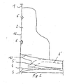
- FIG. 2 shows the insertion region 2 of a gas generator (not shown) with different seam progressions.
- the fabric blank of the airbag 1 along a seam 12 is superposed, with semicircular punched holes 6 are provided for the passage of fastening bolts, which are arranged on the gas generator. These punched holes or recesses 6 allow a passage of the usually cylindrical fastening bolts.
- the receiving area 2 of the gas generator can be separated or delimited via a stitching seam.
- An insertion opening 10 is provided in a fabric layer in the form of a slot.
- the conventional seam course of a peripheral seam 4 ' is shown by a dashed line, the residual thread projection 5' of the conventional circumferential seam 4 'can lead to disturbances in the area of the electrical contacting.
- the inventive new seam course of the peripheral seam 4 is shown in a solid line.
- the residual thread projection 5, which consists of a locked warp thread, is arranged far away from the insertion opening 10, so that the residual thread projection 5 of the seam seam thread can not get into the plug region.
- the warp seam can be locked.
- FIG. 3 shows a variant of the invention with an inserted gas generator 3 and an electrical contact 31.
- the residual thread projection 5 is fixed to the airbag fabric via a stitching seam.
- FIG. 4 shows a seam course similar to FIG. 2.
- the insertion opening 10 is formed as a slot.
- a fabric portion 42 is formed, which is folded after insertion of a gas generator 3, as shown in Figure 5, back and up, so that arranged on the back of the insertion opening 10 fabric layer the tissue area 2 comes to rest on each other.
- the folded state is shown in FIG.
- the fabric area 42 is placed on the back of the airbag 1 and the receiving area 2 and fixed, for example glued, sewn or welded. As a result, the residual thread projection of the hem seam 4 is moved out of the region of the electrical contact.
- FIG. 6 A variant of the invention is shown in Figure 6, in which the receiving area 2 is shown.
- the insertion opening 10 is produced by an incision, which is introduced above the hem seam 4, starting from the folded edge 12, in the direction of the airbag fabric through both fabric layers.
- the resulting tab 7 is folded away by a folded edge 8 of the folding edge 12, so that the seam seam supernatant 5 out of reach of the insertion opening 10 is fixed becomes.
- the flap 7 can be fixed via a stitching seam 9.
- other methods of attachment can be chosen, for example by gluing or welding.
- the airbag fabric can also be inserted or inverted inside the chamber.
- a locking or fixing of the invaginated airbag fabric area with the protruding, locked end of the seam seam is provided.
- the embodiment of the invention is not limited to side airbags, but can also be used in other airbags with a corresponding seam.
Abstract
Description
Die Erfindung betrifft einen Airbag aus einem Airbaggewebe, insbesondere für einen Seitenairbag, das mit zumindest einer teilumfänglichen Umfangsnaht eine doppellagige Kammer ausbildet, in der eine Einführöffnung für einen Gasgenerator vorgesehen ist.The invention relates to an airbag made of an airbag fabric, in particular for a side airbag, which forms a double-layered chamber with at least one partially circumferential seam in which an introduction opening for a gas generator is provided.
Die Erfindung ist insbesondere für einen Kopf-Thorax-Airbag vorgesehen, bei dem eine Einführöffnung des Gasgenerators in der Nähe eines verriegelten Nahtendes einer Umfangsnaht oder einer Saumnaht angeordnet ist.The invention is particularly intended for a head-thorax airbag, in which an insertion opening of the gas generator is arranged in the vicinity of a locked seam end of a peripheral seam or a seam seam.
Airbags sind in einem weiten Umfang in Kraftfahrzeugen vorgesehen, um bei einem Unfall oder bei einem bevorstehenden Unfall ein Polster durch einen aufgeblasenen Gassack zu bilden. Der Gassack besteht in der Regel aus einem Gewebe, das doppellagig ausgeführt ist und eine oder mehrere Kammern ausbildet. Neben einer einstückig gewobenen Ausbildung des Airbags kann dieser auch aus einem Airbaggewebezuschnitt genäht werden. Um zwei aufeinander gelegte Gewebeabschnitte miteinander zu verbinden, wird eine Umfangsnaht erzeugt, über die gegebenenfalls in Zusammenwirkung mit einer Falzkante eine im Wesentlichen geschlossene Kammer entsteht. Die Befüllung dieser Kammer erfolgt über einen Gasgenerator, der über eine elektrische Steckverbindung mit einer Steuereinheit verbunden ist. Wird ein Unfall oder ein bevorstehender Unfall detektiert, wird von der Steuereinheit ein entsprechendes Signal an den Gasgenerator übermittelt und dieser gezündet. Da ein Airbag nur im aufgeblasenen Zustand seine Wirksamkeit entfaltet, sind höchste Zuverlässigkeitsanforderungen an den Gasgenerator über die gesamte erwartete Lebensdauer des Kraftfahrzeuges zu stellen.Airbags are widely used in motor vehicles to form a cushion through an inflated airbag in the event of an accident or imminent accident. The gas bag is usually made of a fabric that is double-layered and one or more chambers forms. In addition to an integrally woven design of the airbag this can also be sewn from an airbag fabric blank. In order to connect two superimposed tissue sections with each other, a peripheral seam is produced, via which optionally in cooperation with a folded edge, a substantially closed chamber arises. The filling of this chamber via a gas generator, which is connected via an electrical plug connection with a control unit. If an accident or an imminent accident is detected, the control unit transmits a corresponding signal to the gas generator and ignites it. Since an airbag develops its effectiveness only when inflated, highest reliability requirements are to be placed on the gas generator over the entire expected service life of the motor vehicle.
Der Einbau von Airbags und Gasgeneratoren in ein Kraftfahrzeug erfordert in einem großen Umfang Handarbeit, da diese Komponenten erst relativ spät zusammen mit der Innenausstattung montiert werden. Während der Gasgenerator und das Airbaggewebe bereits vormontiert werden können, kann eine elektrische Kontaktierung mit einem Stecker der Steuereinheit erst beim oder nach dem Einbau des Airbags in das Fahrzeug erfolgen.The installation of airbags and gas generators in a motor vehicle requires handwork to a large extent, since these components are assembled relatively late together with the interior. While the gas generator and the airbag fabric can already be preassembled, an electrical contact with a plug of the control unit can only take place during or after the installation of the airbag in the vehicle.
Bei einer entsprechenden Nahtführung besteht das Problem, dass ein Restfadenüberstand der Umfangs- oder Saumnaht in dem Bereich der elektrischen Kontaktierung des Gasgenerators gelangen und beim Kontaktieren Probleme verursachen kann. Es kann der Fall auftreten, dass der Restfadenüberstand beim Kontaktieren des Gasgenerators zwischen einem Kabelstecker von der Steuereinheit und einem Gasgenerator-Interface gelangen und darin eingeklemmt werden kann. Dadurch wird eine so genannte Scheinverrastung hervorgerufen, bei der eine mechanisch feste, elektrisch jedoch nicht einwandfreie Anbringung des Steckers an dem Gasgenerator erfolgt. Ebenfalls ist es möglich, da gegebenenfalls vorgesehene, formschlüssige Verrastungselemente nicht richtig miteinander eingreifen, dass sich der Kabelstecker von dem Gasgenerator wieder lösen kann, was zu einer Aufhebung der elektrischen Kontaktierung oder zu einer Fehlermeldung in der Fahrzeugelektronik führt.With a corresponding seam guide, there is the problem that a residual thread projection of the circumferential or seam seam in the region of the electrical contacting of the gas generator and can cause problems when contacting. It may be the case that the residual thread projection on contacting the gas generator between a cable connector from the control unit and a gas generator interface can be trapped and clamped therein. As a result, a so-called dummy latching is caused, in which a mechanically fixed, but not properly electrical attachment of the plug takes place on the gas generator. It is also possible, since possibly provided, positive locking elements do not intervene properly that the cable connector can solve the gas generator again, which leads to a cancellation of the electrical contact or an error message in the vehicle electronics.
Aufgabe der vorliegenden Erfindung ist es, einen Airbag bereitzustellen, mit dem Probleme bei der elektrischen Kontaktierung vermieden und eine sicherer Verrastung sichergestellt werden kann.Object of the present invention is to provide an airbag, avoided with the problems of electrical contact and secure locking can be ensured.
Erfindungsgemäß wird diese Aufgabe durch einen Airbag mit den Merkmalen des Anspruchs 1 gelöst. Vorteilhafte Ausgestaltungen und Weiterbildungen der Erfindung sind in den Unteransprüchen aufgeführt.According to the invention this object is achieved by an airbag having the features of
Der erfindungsgemäße Airbag aus einem Airbaggewebe mit einer zumindest teilumfänglichen Umfangsnaht, die eine doppellagige Kammer ausbildet, in der eine Einführöffnung für einen Gasgenerator vorgesehen ist, sieht vor, dass ein Restfadenüberstand im Bereich der Einführöffnung fixiert oder mit dem Airbaggewebe bzw. einem Teil des Airbaggewebes umgeklappt und anschließend fixiert ist. Dadurch wird der Restfadenüberstand aus dem Bereich der Kontaktierung bzw. aus dem Einflussbereich des Gasgenerators verlegt, so dass eine Scheinverrastung wirksam ausgeschlossen werden kann.The airbag according to the invention of an airbag fabric having an at least partially circumferential seam forming a double-layered chamber in which an insertion opening is provided for a gas generator, provides that a residual thread projection in the region of the insertion opening fixed or folded with the airbag fabric or a part of the airbag fabric and then fixed. As a result, the residual thread projection is moved out of the area of the contacting or out of the area of influence of the gas generator, so that false locking can be effectively ruled out.
Eine Weiterbildung sieht vor, dass der Restfadenüberstand vernäht, verklebt oder verschweißt und dadurch an dem Airbaggewebe wirksam und dauerhaft festgelegt ist. Die Festlegung muss jedoch nur bis zur Montage des Gasgenerators aufrechterhalten bleiben.A further embodiment provides that the residual thread projection is sewn, glued or welded and thereby effectively and permanently fixed to the airbag fabric. The determination, however, must be maintained only until the assembly of the gas generator.
Ebenfalls ist es vorgesehen, dass das Airbaggewebe mit dem Restfadenüberstand von der Einführöffnung weggeklappt ist, um das Nahtende aus dem Bereich des Gasgenerators oder der Kontaktierung des Gasgenerators herauszubewegen. Dieses Wegklappen dichtet gleichzeitig die Einführöffnung gegen den Gasgenerator ab, so dass dies zu einer erhöhten Dichtigkeit des Airbags beiträgt.It is also provided that the airbag fabric with the residual thread projection is folded away from the insertion opening in order to move the seam end out of the region of the gas generator or of the contacting of the gas generator. This folding away at the same time seals the insertion opening against the gas generator, so that this contributes to an increased tightness of the airbag.
Ebenfalls ist vorgesehen, dass das Airbaggewebe, das den Restfadenüberstand aufweist, nach innen in die Kammer eingeklappt ist, um den Restfadenüberstand nicht in den Bereich der elektrischen Kontaktierung des Gasgenerators gelangen zu lassen.It is also provided that the airbag fabric, which has the residual thread projection, is folded inwards into the chamber in order not to allow the residual thread projection to reach the region of electrical contacting of the gas generator.
Bei einem weggeklappten Airbaggewebe ist es vorgesehen, dass dieser geklappte Gewebeteil festgenäht, verklebt oder verschweißt ist, wodurch eine Festlegung des weggeklappten Gewebeabschnittes an dem übrigen Airbaggewebe erfolgt.In a folded-away airbag fabric, it is provided that this folded fabric part is sewn, glued or welded, whereby a determination of the folded-away fabric section takes place on the remaining airbag fabric.
Eine Variante der Erfindung sieht vor, dass die Einführöffnung im Bereich einer Falzkante des Airbaggewebes durch einen Schlitz ausgebildet wird, der durch beide Gewebelagen hindurchgeht. Dadurch entsteht ein Lappen unterhalb der Einführöffnung, in dem der Restfadenüberstand angeordnet ist. Dieser Lappen wird umgeklappt und fixiert, wodurch einerseits ein Abdichten der Einführöffnung gegenüber dem Gasgenerator erfolgt und andererseits der Restfadenüberstand mitsamt dem Lappen aus der Kontaktierungszone entfernt wird.A variant of the invention provides that the insertion opening in the region of a folded edge of the airbag fabric is formed by a slot which passes through both fabric layers. This creates a cloth below the insertion opening, in which the residual thread projection is arranged. This flap is folded over and fixed, whereby on the one hand a sealing of the insertion takes place with respect to the gas generator and on the other hand, the residual thread projection is removed together with the flap from the contacting zone.
Nachfolgend werden Ausführungsbeispiele der Erfindung anhand der beigefügten Figuren näher erläutert. Gleiche Bezugszeichen in den Figuren bezeichnen gleiche Elemente.
- Figur 1 -
- einen herkömmlichen Airbag in Draufsicht;
- Figur 2 -
- eine Detaildarstellung einer erfindungsgemäßen Variante;
- Figur 3 -
- eine Detailansicht mit einer fixierten Umfangsnaht;
- Figur 4 -
- eine Detailansicht vor dem Einführen eines Gasgenerators;
- Figur 5 -
- eine Ausgestaltung gemäß
Figur 4 nach Einführen eines Gasgenerators und Umklappen eines Airbaggewebebereiches; sowie - Figur 6 -
- eine Variante des Airbags mit einem umgeklappten Lappen.
- FIG. 1 -
- a conventional airbag in plan view;
- FIG. 2 -
- a detailed representation of a variant according to the invention;
- FIG. 3 -
- a detailed view with a fixed circumferential seam;
- FIG. 4 -
- a detailed view before inserting a gas generator;
- FIG. 5 -
- an embodiment according to Figure 4 after insertion of a gas generator and folding over an airbag tissue area; such as
- FIG. 6 -
- a variant of the airbag with a folded flap.
In der Figur 1 ist in Seitenansicht ein Airbag aus einem Airbaggewebe mit vorliegend einer Kammer gezeigt. Auch mehrkammerige Airbags können vorgesehen sein. Der Airbag 1 ist durch einen Airbaggewebezuschnitt gebildet, der entlang einer Falzkante 12 gefaltet und über eine Umfangsnaht 4 unter Ausbildung einer Kammer vernäht ist. In der Kammer ist ein Aufnahmebereich 2 für einen Gasgenerator 3 vorgesehen, der über eine Einführöffnung 10 in den Aufnahmebereich 2 eingeführt wird. Ein Restfadenüberstand 5 der Umfangsnaht 4 bzw. einer Saumnaht kann bei einer elektrischen Kontaktierung an dem aus der Einführöffnung 10 des Airbags 1 herausragenden Teil des Gasgenerators 3 anliegen und eine Scheinkontaktierung bzw. eine elektrische Unterbrechung bewirken.FIG. 1 shows a side view of an airbag made of an airbag fabric with a chamber in the present case. Also multi-chambered airbags can be provided. The
In der Figur 2 ist der Einführbereich 2 eines nicht dargestellten Gasgenerators mit verschiedenen Nahtverläufen gezeigt. Auch hier ist der Gewebezuschnitt des Airbags 1 entlang einer Falznaht 12 aufeinander gelegt, wobei halbkreisförmige Ausstanzungen 6 zum Durchtritt von Befestigungsbolzen, die an dem Gasgenerator angeordnet sind, vorgesehen sind. Diese Ausstanzungen oder Ausnehmungen 6 ermöglichen einen Durchtritt der in der Regel zylindrischen Befestigungsbolzen. Der Aufnahmebereich 2 des Gasgenerators kann über eine Heftnaht abgetrennt bzw. abgegrenzt sein. Eine Einführöffnung 10 ist in einer Gewebelage in Gestalt eines Schlitzes vorgesehen. Der herkömmliche Nahtverlauf einer Umfangsnaht 4' ist durch eine gestrichelte Linie dargestellt, der Restfadenüberstand 5' der herkömmlichen Umfangsnaht 4' kann im Bereich der elektrischen Kontaktierung zu Störungen führen. Der erfindungsgemäße neue Nahtverlauf der Umfangsnaht 4 ist in einer durchgezogenen Linie dargestellt. Der Restfadenüberstand 5, der aus einem verriegelten Kettnahtfaden besteht, ist weit weg von der Einführöffnung 10 angeordnet, so dass der Restfadenüberstand 5 des Saumnahtfadens nicht in den Steckerbereich gelangen kann. Die Kettnaht kann dabei verriegelt sein.FIG. 2 shows the
In der Figur 3 ist eine Variante der Erfindung mit einem eingeführten Gasgenerator 3 und einer elektrischen Kontaktierung 31 gezeigt. Der Restfadenüberstand 5 ist über eine Heftnaht an dem Airbaggewebe fixiert.FIG. 3 shows a variant of the invention with an inserted
In der Figur 4 ist ein Nahtverlauf ähnlich der Figur 2 gezeigt. Die Einführöffnung 10 ist als Schlitz ausgebildet. Zwischen der Einführöffnung 10 und der Saumnaht 4 ist ein Gewebebereich 42 ausgebildet, der nach dem Einführen eines Gasgenerators 3, wie es in der Figur 5 gezeigt ist, nach hinten und oben umgeschlagen wird, so dass die auf der Rückseite der Einführöffnung 10 angeordnete Gewebelage mit dem Gewebebereich 2 aufeinander zu liegen kommt. Der umgeklappte Zustand ist in der Figur 5 dargestellt. Der Gewebebereich 42 wird auf der Rückseite des Airbags 1 bzw. des Aufnahmebereiches 2 aufgelegt und fixiert, beispielsweise verklebt, vernäht oder verschweißt. Dadurch wird der Restfadenüberstand der Saumnaht 4 aus dem Bereich der elektrischen Kontaktierung herausbewegt.FIG. 4 shows a seam course similar to FIG. 2. The
Eine Variante der Erfindung ist in der Figur 6 dargestellt, bei der der Aufnahmebereich 2 dargestellt ist. Die Einführöffnung 10 wird durch einen Einschnitt erzeugt, der oberhalb der Saumnaht 4, von der Falzkante 12 ausgehend, in Richtung auf das Airbaggewebe durch beide Gewebelagen hindurch eingebracht wird. Der dadurch entstehende Lappen 7 wird um eine Faltkante 8 von der Falzkante 12 weggefaltet, so dass der Saumnahtüberstand 5 außerhalb der Reichweite der Einführöffnung 10 fixiert wird. Der Lappen 7 kann über eine Heftnaht 9 fixiert sein. Alternativ können andere Festlegungsmethoden gewählt werden, beispielsweise verkleben oder verschweißen.A variant of the invention is shown in Figure 6, in which the receiving
Sowohl durch das Umlegen gemäß der Figur 5 als auch gemäß der Figur 6 wird eine verbesserte Abdichtung der Einführöffnung 10 durch ein engeres Anliegen des Airbaggewebes an dem Gasgenerator 3 bewirkt. Die Fixiernaht 9 legt in der Figur 6 den Lappen des eingeschnittenen Airbaggewebes fest.Both by the folding according to the figure 5 and according to the figure 6, an improved sealing of the
Alternativ kann das Airbaggewebe auch nach innen in die Kammer eingeführt bzw. eingestülpt werden. Eine Verriegelung oder Fixierung des eingestülpten Airbaggewebebereiches mit dem überstehenden, verriegelten Ende der Saumnaht ist vorgesehen.Alternatively, the airbag fabric can also be inserted or inverted inside the chamber. A locking or fixing of the invaginated airbag fabric area with the protruding, locked end of the seam seam is provided.
Die erfindungsgemäße Ausgestaltung ist nicht auf Seitenairbags beschränkt, sondern kann auch bei anderen Airbags bei einem entsprechenden Nahtverlauf eingesetzt werden.The embodiment of the invention is not limited to side airbags, but can also be used in other airbags with a corresponding seam.
Claims (7)
Applications Claiming Priority (1)
| Application Number | Priority Date | Filing Date | Title |
|---|---|---|---|
| DE102006025017 | 2006-05-26 |
Publications (2)
| Publication Number | Publication Date |
|---|---|
| EP1860001A1 true EP1860001A1 (en) | 2007-11-28 |
| EP1860001B1 EP1860001B1 (en) | 2010-07-21 |
Family
ID=38293360
Family Applications (1)
| Application Number | Title | Priority Date | Filing Date |
|---|---|---|---|
| EP07009790A Not-in-force EP1860001B1 (en) | 2006-05-26 | 2007-05-16 | Air bag with a sewed or folded surrounding stitched end of seam |
Country Status (3)
| Country | Link |
|---|---|
| EP (1) | EP1860001B1 (en) |
| AT (1) | ATE474744T1 (en) |
| DE (1) | DE502007004449D1 (en) |
Citations (4)
| Publication number | Priority date | Publication date | Assignee | Title |
|---|---|---|---|---|
| FR2724626A1 (en) * | 1994-09-20 | 1996-03-22 | Aerazur | Method of stitching of vehicle inflatable air bag |
| DE20105734U1 (en) * | 2001-04-02 | 2001-08-30 | Trw Repa Gmbh | Airbag module for a vehicle occupant restraint system |
| DE20218550U1 (en) * | 2002-11-29 | 2003-04-03 | Trw Repa Gmbh | Airbag for a vehicle occupant restraint system has a reinforced layer which projects out in the area of the edging of the blowing-in hole |
| EP1580085A2 (en) * | 2004-03-16 | 2005-09-28 | Key Safety Systems, Inc. | Airbag cover |
-
2007
- 2007-05-16 EP EP07009790A patent/EP1860001B1/en not_active Not-in-force
- 2007-05-16 AT AT07009790T patent/ATE474744T1/en active
- 2007-05-16 DE DE502007004449T patent/DE502007004449D1/en active Active
Patent Citations (4)
| Publication number | Priority date | Publication date | Assignee | Title |
|---|---|---|---|---|
| FR2724626A1 (en) * | 1994-09-20 | 1996-03-22 | Aerazur | Method of stitching of vehicle inflatable air bag |
| DE20105734U1 (en) * | 2001-04-02 | 2001-08-30 | Trw Repa Gmbh | Airbag module for a vehicle occupant restraint system |
| DE20218550U1 (en) * | 2002-11-29 | 2003-04-03 | Trw Repa Gmbh | Airbag for a vehicle occupant restraint system has a reinforced layer which projects out in the area of the edging of the blowing-in hole |
| EP1580085A2 (en) * | 2004-03-16 | 2005-09-28 | Key Safety Systems, Inc. | Airbag cover |
Also Published As
| Publication number | Publication date |
|---|---|
| EP1860001B1 (en) | 2010-07-21 |
| DE502007004449D1 (en) | 2010-09-02 |
| ATE474744T1 (en) | 2010-08-15 |
Similar Documents
| Publication | Publication Date | Title |
|---|---|---|
| DE102008060858B4 (en) | Knee airbag | |
| DE102005057439B4 (en) | Vehicle seat assembly | |
| EP1772330B1 (en) | Airbag for an airbag module of a motor vehicle | |
| DE202007015431U1 (en) | Airbag device for protecting a vehicle occupant | |
| DE102010026932A1 (en) | Airbag with an external tension element and method for its production | |
| EP2389304B1 (en) | Airbag for a vehicle occupant restraint system and method for producing an airbag | |
| EP1860001B1 (en) | Air bag with a sewed or folded surrounding stitched end of seam | |
| WO2016156342A1 (en) | Securing arrangement for securing an airbag to a chassis-side support wall of a vehicle | |
| EP1737708B1 (en) | Airbag module comprising a gas generator and an airbag | |
| WO2008022889A1 (en) | Airbag covering | |
| DE102015111873B4 (en) | Airbag with attachment for a gas generator | |
| DE10242023A1 (en) | Airbag for vehicle seat, has continuous tube formed from flexible and/or woven material such that airbag displays unstable cross section in its deflated state and airbag is made gastight with closing unit for closing tube ends | |
| DE102008034383B4 (en) | Airbag cover and airbag module with an airbag cover | |
| EP2419304A1 (en) | Airbag arrangement for a vehicle occupant restraint system and method for producing an airbag arrangement | |
| DE102007022974B4 (en) | Airbag module | |
| EP1757493A1 (en) | Airbag for a vehicle passenger restraint system | |
| DE10223189A1 (en) | Airbag for car passenger safety system has two casing layers joined together along peripheral edges with at least one other connection to define thickness of inflated bag | |
| DE102008046265A1 (en) | Gas bag for gas bag arrangement for protection of passenger, is provided with two closing elements, which are provided along edge of ventilation opening | |
| WO2014106528A1 (en) | Airbag, airbag module, and method for assembling an airbag module | |
| DE102009034557B4 (en) | airbag | |
| WO2008155106A1 (en) | Airbag module for installation in a steering wheel body | |
| DE102010032175B4 (en) | airbag | |
| DE102016120368A1 (en) | Airbag unit | |
| EP2197712B1 (en) | Gas bag module for a vehicle occupant restrain system and method for manufacturing a gas bag module | |
| DE102007015042B4 (en) | Airbag and method for its production |
Legal Events
| Date | Code | Title | Description |
|---|---|---|---|
| PUAI | Public reference made under article 153(3) epc to a published international application that has entered the european phase |
Free format text: ORIGINAL CODE: 0009012 |
|
| AK | Designated contracting states |
Kind code of ref document: A1 Designated state(s): AT BE BG CH CY CZ DE DK EE ES FI FR GB GR HU IE IS IT LI LT LU LV MC MT NL PL PT RO SE SI SK TR |
|
| AX | Request for extension of the european patent |
Extension state: AL BA HR MK YU |
|
| 17P | Request for examination filed |
Effective date: 20080213 |
|
| 17Q | First examination report despatched |
Effective date: 20080318 |
|
| AKX | Designation fees paid |
Designated state(s): AT BE BG CH CY CZ DE DK EE ES FI FR GB GR HU IE IS IT LI LT LU LV MC MT NL PL PT RO SE SI SK TR |
|
| GRAP | Despatch of communication of intention to grant a patent |
Free format text: ORIGINAL CODE: EPIDOSNIGR1 |
|
| GRAS | Grant fee paid |
Free format text: ORIGINAL CODE: EPIDOSNIGR3 |
|
| GRAA | (expected) grant |
Free format text: ORIGINAL CODE: 0009210 |
|
| AK | Designated contracting states |
Kind code of ref document: B1 Designated state(s): AT BE BG CH CY CZ DE DK EE ES FI FR GB GR HU IE IS IT LI LT LU LV MC MT NL PL PT RO SE SI SK TR |
|
| REG | Reference to a national code |
Ref country code: GB Ref legal event code: FG4D Free format text: NOT ENGLISH |
|
| REG | Reference to a national code |
Ref country code: CH Ref legal event code: EP |
|
| REG | Reference to a national code |
Ref country code: IE Ref legal event code: FG4D |
|
| REF | Corresponds to: |
Ref document number: 502007004449 Country of ref document: DE Date of ref document: 20100902 Kind code of ref document: P |
|
| REG | Reference to a national code |
Ref country code: NL Ref legal event code: VDEP Effective date: 20100721 |
|
| LTIE | Lt: invalidation of european patent or patent extension |
Effective date: 20100721 |
|
| PG25 | Lapsed in a contracting state [announced via postgrant information from national office to epo] |
Ref country code: NL Free format text: LAPSE BECAUSE OF FAILURE TO SUBMIT A TRANSLATION OF THE DESCRIPTION OR TO PAY THE FEE WITHIN THE PRESCRIBED TIME-LIMIT Effective date: 20100721 Ref country code: LT Free format text: LAPSE BECAUSE OF FAILURE TO SUBMIT A TRANSLATION OF THE DESCRIPTION OR TO PAY THE FEE WITHIN THE PRESCRIBED TIME-LIMIT Effective date: 20100721 Ref country code: FI Free format text: LAPSE BECAUSE OF FAILURE TO SUBMIT A TRANSLATION OF THE DESCRIPTION OR TO PAY THE FEE WITHIN THE PRESCRIBED TIME-LIMIT Effective date: 20100721 |
|
| REG | Reference to a national code |
Ref country code: IE Ref legal event code: FD4D |
|
| PG25 | Lapsed in a contracting state [announced via postgrant information from national office to epo] |
Ref country code: CY Free format text: LAPSE BECAUSE OF FAILURE TO SUBMIT A TRANSLATION OF THE DESCRIPTION OR TO PAY THE FEE WITHIN THE PRESCRIBED TIME-LIMIT Effective date: 20100721 Ref country code: IS Free format text: LAPSE BECAUSE OF FAILURE TO SUBMIT A TRANSLATION OF THE DESCRIPTION OR TO PAY THE FEE WITHIN THE PRESCRIBED TIME-LIMIT Effective date: 20101121 Ref country code: PL Free format text: LAPSE BECAUSE OF FAILURE TO SUBMIT A TRANSLATION OF THE DESCRIPTION OR TO PAY THE FEE WITHIN THE PRESCRIBED TIME-LIMIT Effective date: 20100721 Ref country code: PT Free format text: LAPSE BECAUSE OF FAILURE TO SUBMIT A TRANSLATION OF THE DESCRIPTION OR TO PAY THE FEE WITHIN THE PRESCRIBED TIME-LIMIT Effective date: 20101122 Ref country code: SI Free format text: LAPSE BECAUSE OF FAILURE TO SUBMIT A TRANSLATION OF THE DESCRIPTION OR TO PAY THE FEE WITHIN THE PRESCRIBED TIME-LIMIT Effective date: 20100721 Ref country code: BG Free format text: LAPSE BECAUSE OF FAILURE TO SUBMIT A TRANSLATION OF THE DESCRIPTION OR TO PAY THE FEE WITHIN THE PRESCRIBED TIME-LIMIT Effective date: 20101021 |
|
| PG25 | Lapsed in a contracting state [announced via postgrant information from national office to epo] |
Ref country code: SE Free format text: LAPSE BECAUSE OF FAILURE TO SUBMIT A TRANSLATION OF THE DESCRIPTION OR TO PAY THE FEE WITHIN THE PRESCRIBED TIME-LIMIT Effective date: 20100721 Ref country code: LV Free format text: LAPSE BECAUSE OF FAILURE TO SUBMIT A TRANSLATION OF THE DESCRIPTION OR TO PAY THE FEE WITHIN THE PRESCRIBED TIME-LIMIT Effective date: 20100721 Ref country code: GR Free format text: LAPSE BECAUSE OF FAILURE TO SUBMIT A TRANSLATION OF THE DESCRIPTION OR TO PAY THE FEE WITHIN THE PRESCRIBED TIME-LIMIT Effective date: 20101022 |
|
| PG25 | Lapsed in a contracting state [announced via postgrant information from national office to epo] |
Ref country code: DK Free format text: LAPSE BECAUSE OF FAILURE TO SUBMIT A TRANSLATION OF THE DESCRIPTION OR TO PAY THE FEE WITHIN THE PRESCRIBED TIME-LIMIT Effective date: 20100721 Ref country code: IE Free format text: LAPSE BECAUSE OF FAILURE TO SUBMIT A TRANSLATION OF THE DESCRIPTION OR TO PAY THE FEE WITHIN THE PRESCRIBED TIME-LIMIT Effective date: 20100721 |
|
| PLBE | No opposition filed within time limit |
Free format text: ORIGINAL CODE: 0009261 |
|
| STAA | Information on the status of an ep patent application or granted ep patent |
Free format text: STATUS: NO OPPOSITION FILED WITHIN TIME LIMIT |
|
| PG25 | Lapsed in a contracting state [announced via postgrant information from national office to epo] |
Ref country code: EE Free format text: LAPSE BECAUSE OF FAILURE TO SUBMIT A TRANSLATION OF THE DESCRIPTION OR TO PAY THE FEE WITHIN THE PRESCRIBED TIME-LIMIT Effective date: 20100721 Ref country code: RO Free format text: LAPSE BECAUSE OF FAILURE TO SUBMIT A TRANSLATION OF THE DESCRIPTION OR TO PAY THE FEE WITHIN THE PRESCRIBED TIME-LIMIT Effective date: 20100721 Ref country code: SK Free format text: LAPSE BECAUSE OF FAILURE TO SUBMIT A TRANSLATION OF THE DESCRIPTION OR TO PAY THE FEE WITHIN THE PRESCRIBED TIME-LIMIT Effective date: 20100721 Ref country code: CZ Free format text: LAPSE BECAUSE OF FAILURE TO SUBMIT A TRANSLATION OF THE DESCRIPTION OR TO PAY THE FEE WITHIN THE PRESCRIBED TIME-LIMIT Effective date: 20100721 Ref country code: IT Free format text: LAPSE BECAUSE OF FAILURE TO SUBMIT A TRANSLATION OF THE DESCRIPTION OR TO PAY THE FEE WITHIN THE PRESCRIBED TIME-LIMIT Effective date: 20100721 |
|
| 26N | No opposition filed |
Effective date: 20110426 |
|
| PG25 | Lapsed in a contracting state [announced via postgrant information from national office to epo] |
Ref country code: ES Free format text: LAPSE BECAUSE OF FAILURE TO SUBMIT A TRANSLATION OF THE DESCRIPTION OR TO PAY THE FEE WITHIN THE PRESCRIBED TIME-LIMIT Effective date: 20101101 |
|
| REG | Reference to a national code |
Ref country code: DE Ref legal event code: R097 Ref document number: 502007004449 Country of ref document: DE Effective date: 20110426 |
|
| BERE | Be: lapsed |
Owner name: AUTOLIV DEVELOPMENT A.B. Effective date: 20110531 |
|
| PG25 | Lapsed in a contracting state [announced via postgrant information from national office to epo] |
Ref country code: MC Free format text: LAPSE BECAUSE OF NON-PAYMENT OF DUE FEES Effective date: 20110531 Ref country code: MT Free format text: LAPSE BECAUSE OF FAILURE TO SUBMIT A TRANSLATION OF THE DESCRIPTION OR TO PAY THE FEE WITHIN THE PRESCRIBED TIME-LIMIT Effective date: 20100721 |
|
| REG | Reference to a national code |
Ref country code: CH Ref legal event code: PL |
|
| GBPC | Gb: european patent ceased through non-payment of renewal fee |
Effective date: 20110516 |
|
| PG25 | Lapsed in a contracting state [announced via postgrant information from national office to epo] |
Ref country code: CH Free format text: LAPSE BECAUSE OF NON-PAYMENT OF DUE FEES Effective date: 20110531 Ref country code: LI Free format text: LAPSE BECAUSE OF NON-PAYMENT OF DUE FEES Effective date: 20110531 |
|
| REG | Reference to a national code |
Ref country code: FR Ref legal event code: ST Effective date: 20120131 |
|
| PG25 | Lapsed in a contracting state [announced via postgrant information from national office to epo] |
Ref country code: BE Free format text: LAPSE BECAUSE OF NON-PAYMENT OF DUE FEES Effective date: 20110531 |
|
| PG25 | Lapsed in a contracting state [announced via postgrant information from national office to epo] |
Ref country code: FR Free format text: LAPSE BECAUSE OF NON-PAYMENT OF DUE FEES Effective date: 20110531 |
|
| PG25 | Lapsed in a contracting state [announced via postgrant information from national office to epo] |
Ref country code: GB Free format text: LAPSE BECAUSE OF NON-PAYMENT OF DUE FEES Effective date: 20110516 |
|
| PG25 | Lapsed in a contracting state [announced via postgrant information from national office to epo] |
Ref country code: LU Free format text: LAPSE BECAUSE OF NON-PAYMENT OF DUE FEES Effective date: 20110516 |
|
| REG | Reference to a national code |
Ref country code: AT Ref legal event code: MM01 Ref document number: 474744 Country of ref document: AT Kind code of ref document: T Effective date: 20120516 |
|
| PG25 | Lapsed in a contracting state [announced via postgrant information from national office to epo] |
Ref country code: AT Free format text: LAPSE BECAUSE OF NON-PAYMENT OF DUE FEES Effective date: 20120516 |
|
| PG25 | Lapsed in a contracting state [announced via postgrant information from national office to epo] |
Ref country code: TR Free format text: LAPSE BECAUSE OF FAILURE TO SUBMIT A TRANSLATION OF THE DESCRIPTION OR TO PAY THE FEE WITHIN THE PRESCRIBED TIME-LIMIT Effective date: 20100721 |
|
| PG25 | Lapsed in a contracting state [announced via postgrant information from national office to epo] |
Ref country code: HU Free format text: LAPSE BECAUSE OF FAILURE TO SUBMIT A TRANSLATION OF THE DESCRIPTION OR TO PAY THE FEE WITHIN THE PRESCRIBED TIME-LIMIT Effective date: 20100721 |
|
| REG | Reference to a national code |
Ref country code: DE Ref legal event code: R082 Ref document number: 502007004449 Country of ref document: DE Representative=s name: GRAMM, LINS & PARTNER PATENT- UND RECHTSANWAEL, DE |
|
| PGFP | Annual fee paid to national office [announced via postgrant information from national office to epo] |
Ref country code: DE Payment date: 20180530 Year of fee payment: 12 |
|
| REG | Reference to a national code |
Ref country code: DE Ref legal event code: R119 Ref document number: 502007004449 Country of ref document: DE |
|
| PG25 | Lapsed in a contracting state [announced via postgrant information from national office to epo] |
Ref country code: DE Free format text: LAPSE BECAUSE OF NON-PAYMENT OF DUE FEES Effective date: 20191203 |