EP1859500B1 - Plaque bipolaire pour pile a combustible a tole de distribution metallique deformee - Google Patents
Plaque bipolaire pour pile a combustible a tole de distribution metallique deformee Download PDFInfo
- Publication number
- EP1859500B1 EP1859500B1 EP06726245A EP06726245A EP1859500B1 EP 1859500 B1 EP1859500 B1 EP 1859500B1 EP 06726245 A EP06726245 A EP 06726245A EP 06726245 A EP06726245 A EP 06726245A EP 1859500 B1 EP1859500 B1 EP 1859500B1
- Authority
- EP
- European Patent Office
- Prior art keywords
- bipolar plate
- plate according
- fuel cell
- electrode
- bipolar
- Prior art date
- Legal status (The legal status is an assumption and is not a legal conclusion. Google has not performed a legal analysis and makes no representation as to the accuracy of the status listed.)
- Expired - Lifetime
Links
Images


Classifications
-
- H—ELECTRICITY
- H01—ELECTRIC ELEMENTS
- H01M—PROCESSES OR MEANS, e.g. BATTERIES, FOR THE DIRECT CONVERSION OF CHEMICAL ENERGY INTO ELECTRICAL ENERGY
- H01M8/00—Fuel cells; Manufacture thereof
- H01M8/02—Details
- H01M8/0202—Collectors; Separators, e.g. bipolar separators; Interconnectors
- H01M8/0247—Collectors; Separators, e.g. bipolar separators; Interconnectors characterised by the form
- H01M8/025—Collectors; Separators, e.g. bipolar separators; Interconnectors characterised by the form semicylindrical
-
- C—CHEMISTRY; METALLURGY
- C25—ELECTROLYTIC OR ELECTROPHORETIC PROCESSES; APPARATUS THEREFOR
- C25B—ELECTROLYTIC OR ELECTROPHORETIC PROCESSES FOR THE PRODUCTION OF COMPOUNDS OR NON-METALS; APPARATUS THEREFOR
- C25B1/00—Electrolytic production of inorganic compounds or non-metals
- C25B1/01—Products
- C25B1/02—Hydrogen or oxygen
- C25B1/04—Hydrogen or oxygen by electrolysis of water
-
- C—CHEMISTRY; METALLURGY
- C25—ELECTROLYTIC OR ELECTROPHORETIC PROCESSES; APPARATUS THEREFOR
- C25B—ELECTROLYTIC OR ELECTROPHORETIC PROCESSES FOR THE PRODUCTION OF COMPOUNDS OR NON-METALS; APPARATUS THEREFOR
- C25B9/00—Cells or assemblies of cells; Constructional parts of cells; Assemblies of constructional parts, e.g. electrode-diaphragm assemblies; Process-related cell features
- C25B9/70—Assemblies comprising two or more cells
- C25B9/73—Assemblies comprising two or more cells of the filter-press type
-
- H—ELECTRICITY
- H01—ELECTRIC ELEMENTS
- H01M—PROCESSES OR MEANS, e.g. BATTERIES, FOR THE DIRECT CONVERSION OF CHEMICAL ENERGY INTO ELECTRICAL ENERGY
- H01M8/00—Fuel cells; Manufacture thereof
- H01M8/02—Details
- H01M8/0202—Collectors; Separators, e.g. bipolar separators; Interconnectors
- H01M8/0204—Non-porous and characterised by the material
- H01M8/0206—Metals or alloys
-
- H—ELECTRICITY
- H01—ELECTRIC ELEMENTS
- H01M—PROCESSES OR MEANS, e.g. BATTERIES, FOR THE DIRECT CONVERSION OF CHEMICAL ENERGY INTO ELECTRICAL ENERGY
- H01M8/00—Fuel cells; Manufacture thereof
- H01M8/02—Details
- H01M8/0202—Collectors; Separators, e.g. bipolar separators; Interconnectors
- H01M8/0204—Non-porous and characterised by the material
- H01M8/0223—Composites
- H01M8/0228—Composites in the form of layered or coated products
-
- H—ELECTRICITY
- H01—ELECTRIC ELEMENTS
- H01M—PROCESSES OR MEANS, e.g. BATTERIES, FOR THE DIRECT CONVERSION OF CHEMICAL ENERGY INTO ELECTRICAL ENERGY
- H01M8/00—Fuel cells; Manufacture thereof
- H01M8/02—Details
- H01M8/0202—Collectors; Separators, e.g. bipolar separators; Interconnectors
- H01M8/0247—Collectors; Separators, e.g. bipolar separators; Interconnectors characterised by the form
- H01M8/0254—Collectors; Separators, e.g. bipolar separators; Interconnectors characterised by the form corrugated or undulated
-
- H—ELECTRICITY
- H01—ELECTRIC ELEMENTS
- H01M—PROCESSES OR MEANS, e.g. BATTERIES, FOR THE DIRECT CONVERSION OF CHEMICAL ENERGY INTO ELECTRICAL ENERGY
- H01M8/00—Fuel cells; Manufacture thereof
- H01M8/02—Details
- H01M8/0202—Collectors; Separators, e.g. bipolar separators; Interconnectors
- H01M8/0258—Collectors; Separators, e.g. bipolar separators; Interconnectors characterised by the configuration of channels, e.g. by the flow field of the reactant or coolant
- H01M8/0263—Collectors; Separators, e.g. bipolar separators; Interconnectors characterised by the configuration of channels, e.g. by the flow field of the reactant or coolant having meandering or serpentine paths
-
- C—CHEMISTRY; METALLURGY
- C25—ELECTROLYTIC OR ELECTROPHORETIC PROCESSES; APPARATUS THEREFOR
- C25B—ELECTROLYTIC OR ELECTROPHORETIC PROCESSES FOR THE PRODUCTION OF COMPOUNDS OR NON-METALS; APPARATUS THEREFOR
- C25B1/00—Electrolytic production of inorganic compounds or non-metals
- C25B1/01—Products
- C25B1/02—Hydrogen or oxygen
- C25B1/04—Hydrogen or oxygen by electrolysis of water
- C25B1/042—Hydrogen or oxygen by electrolysis of water by electrolysis of steam
-
- C—CHEMISTRY; METALLURGY
- C25—ELECTROLYTIC OR ELECTROPHORETIC PROCESSES; APPARATUS THEREFOR
- C25B—ELECTROLYTIC OR ELECTROPHORETIC PROCESSES FOR THE PRODUCTION OF COMPOUNDS OR NON-METALS; APPARATUS THEREFOR
- C25B9/00—Cells or assemblies of cells; Constructional parts of cells; Assemblies of constructional parts, e.g. electrode-diaphragm assemblies; Process-related cell features
- C25B9/60—Constructional parts of cells
- C25B9/65—Means for supplying current; Electrode connections; Electric inter-cell connections
-
- C—CHEMISTRY; METALLURGY
- C25—ELECTROLYTIC OR ELECTROPHORETIC PROCESSES; APPARATUS THEREFOR
- C25B—ELECTROLYTIC OR ELECTROPHORETIC PROCESSES FOR THE PRODUCTION OF COMPOUNDS OR NON-METALS; APPARATUS THEREFOR
- C25B9/00—Cells or assemblies of cells; Constructional parts of cells; Assemblies of constructional parts, e.g. electrode-diaphragm assemblies; Process-related cell features
- C25B9/70—Assemblies comprising two or more cells
- C25B9/73—Assemblies comprising two or more cells of the filter-press type
- C25B9/75—Assemblies comprising two or more cells of the filter-press type having bipolar electrodes
-
- C—CHEMISTRY; METALLURGY
- C25—ELECTROLYTIC OR ELECTROPHORETIC PROCESSES; APPARATUS THEREFOR
- C25B—ELECTROLYTIC OR ELECTROPHORETIC PROCESSES FOR THE PRODUCTION OF COMPOUNDS OR NON-METALS; APPARATUS THEREFOR
- C25B9/00—Cells or assemblies of cells; Constructional parts of cells; Assemblies of constructional parts, e.g. electrode-diaphragm assemblies; Process-related cell features
- C25B9/70—Assemblies comprising two or more cells
- C25B9/73—Assemblies comprising two or more cells of the filter-press type
- C25B9/77—Assemblies comprising two or more cells of the filter-press type having diaphragms
-
- Y—GENERAL TAGGING OF NEW TECHNOLOGICAL DEVELOPMENTS; GENERAL TAGGING OF CROSS-SECTIONAL TECHNOLOGIES SPANNING OVER SEVERAL SECTIONS OF THE IPC; TECHNICAL SUBJECTS COVERED BY FORMER USPC CROSS-REFERENCE ART COLLECTIONS [XRACs] AND DIGESTS
- Y02—TECHNOLOGIES OR APPLICATIONS FOR MITIGATION OR ADAPTATION AGAINST CLIMATE CHANGE
- Y02E—REDUCTION OF GREENHOUSE GAS [GHG] EMISSIONS, RELATED TO ENERGY GENERATION, TRANSMISSION OR DISTRIBUTION
- Y02E60/00—Enabling technologies; Technologies with a potential or indirect contribution to GHG emissions mitigation
- Y02E60/30—Hydrogen technology
- Y02E60/36—Hydrogen production from non-carbon containing sources, e.g. by water electrolysis
-
- Y—GENERAL TAGGING OF NEW TECHNOLOGICAL DEVELOPMENTS; GENERAL TAGGING OF CROSS-SECTIONAL TECHNOLOGIES SPANNING OVER SEVERAL SECTIONS OF THE IPC; TECHNICAL SUBJECTS COVERED BY FORMER USPC CROSS-REFERENCE ART COLLECTIONS [XRACs] AND DIGESTS
- Y02—TECHNOLOGIES OR APPLICATIONS FOR MITIGATION OR ADAPTATION AGAINST CLIMATE CHANGE
- Y02E—REDUCTION OF GREENHOUSE GAS [GHG] EMISSIONS, RELATED TO ENERGY GENERATION, TRANSMISSION OR DISTRIBUTION
- Y02E60/00—Enabling technologies; Technologies with a potential or indirect contribution to GHG emissions mitigation
- Y02E60/30—Hydrogen technology
- Y02E60/50—Fuel cells
-
- Y—GENERAL TAGGING OF NEW TECHNOLOGICAL DEVELOPMENTS; GENERAL TAGGING OF CROSS-SECTIONAL TECHNOLOGIES SPANNING OVER SEVERAL SECTIONS OF THE IPC; TECHNICAL SUBJECTS COVERED BY FORMER USPC CROSS-REFERENCE ART COLLECTIONS [XRACs] AND DIGESTS
- Y02—TECHNOLOGIES OR APPLICATIONS FOR MITIGATION OR ADAPTATION AGAINST CLIMATE CHANGE
- Y02P—CLIMATE CHANGE MITIGATION TECHNOLOGIES IN THE PRODUCTION OR PROCESSING OF GOODS
- Y02P70/00—Climate change mitigation technologies in the production process for final industrial or consumer products
- Y02P70/50—Manufacturing or production processes characterised by the final manufactured product
Definitions
- the invention relates to the field of fuel cells operating with a ceramic electrolyte, at high temperature, but also that of electrolysers operating at high temperature and whose operation is the reverse of that of the fuel cell.
- Each base element comprises a membrane sandwiched between two electrodes, namely an anode and a cathode, to which are permanently added an oxidant and a fuel, for example hydrogen and air.
- the bipolar plates make it possible to ensure the supply of these oxidant and fuel on two basic elements each adjacent to this bipolar plate.
- a first concept consists of a stack of elements circular with introduction of fuel and fuel gases by at least one external point and a central point.
- Each element of the stack namely base elements consisting of an electrolyte 1 placed between two electrodes 2A and 2B and bipolar plates 3A and 3B, are circular in shape and have a central hole 4.
- the bipolar plate 3A is a plate placed between two base members, while the pole plate 3B is an end plate.
- the arrows show the circulation paths of air and hydrogen, each in a particular circuit of the bipolar plate. It is found that the hydrogen is introduced through the central hole 4 and is discharged to the outside, while the air is introduced from the outside and discharged to the outside.
- the main disadvantage of this architecture is the fact that the hydrogen is introduced by the central zone, which makes it necessary to ensure a good seal at each base element between the cathode 2A and the central hole 4. This level would cause a combustion between the hydrogen and the air of the cathode compartment, which would cause a significant rise in temperature may cause cracking of ceramic material and thus degrade the performance of the battery.
- Another concept consists of introducing air and hydrogen through the center of the stack, that is to say at the center of each elementary stage. Residual gases are burnt at the peripheral output of the battery.
- This type of concept has the same disadvantages as for the one represented in figure 1 , except that the combustion zone is not in direct contact with the active elements of the battery.
- a third type of concept provides that, for basic elements with flat circular geometry, the introduction of gases is from the outside of the stack.
- the choice of ceramic materials to ensure this function requires to arrange the gas inlets near the periphery of the active areas and can be disadvantageous, in case of loss of sealing and communication from the power supply. air and hydrogen. Again, the appearance of local hot spots may crack parts of the stack.
- the object of the invention is to overcome all these drawbacks and to propose a different concept of fuel and fuel supply for a stack of fuel cells.
- a first main object of the invention is therefore a bipolar plate for fuel cells, intended to be mounted between two electrode / membrane / electrode base elements and having at least two feed holes placed peripherally.
- the plate consists of a rigid metal separator adjacent to at least a first rigid metal distributor consisting of a deformed sheet, so as to form a distribution pipe on each side of the plate, connected to one another by a central hole so as to form a single pipe passing through the distributor and having a first end connected to a feed hole.
- first distributors there are two first distributors on each side of the separator.
- these two distributors are identical.
- a second distributor consisting of a rigid, metal frame in the form of a bowl inside which there is a porous anodic support, this second distributor having an outlet passage peripheral connecting the porous support to a peripheral discharge hole, the separator having in this case a supply channel connecting a feed hole in the center of this separator, so as to open against the porous support.
- the polar plate according to the invention it is intended to use a peripheral seal during the constitution of the stack of a fuel cell, between each bipolar plate according to the invention and the basic elements. at the guard ring and a seal around the feed and / or evacuation holes.
- the geometry of the base elements 10 and bipolar plates 12 according to the invention is circular. Electrodes of each base element 10 are fed respectively from above and below by means of each of a bipolar plate 12 of the same circular geometry. Fuel and fuel supplies, namely hydrogen or air, are made from outside the assembly and brought to the center of each electrode by means of a bipolar plate 12. For example, hydrogen feeds an electrode placed above the bipolar plate 12 concerned while the air feeds the electrode placed below this bipolar plate 12.
- the base elements 10 and the bipolar plates 12 may be of the same diameter.
- each bipolar plate according to the invention consists of a single separator 20, metallic and rigid, consisting of a flat sheet and to ensure the mechanical rigidity of the assembly.
- This is sandwiched between two metal and rigid distributors 14, each constituted by a corrugated sheet which can be obtained, for example, by stamping.
- the distributor 14 has on each side channels 16A and 16B respectively corresponding to the existing separations between the parts of the channel formed on the other side.
- the corrugated sheet constituting each distributor 14 has faces each having a complementary shape. This has a great advantage that is to be able to constitute all distributors by a single type of distributor. In other words, a single kind of room is designed to achieve these elements.
- the channels 16A and 16B each consist of a single channel, for example arranged spirally around the center and ending there.
- the figure 3B shows such a configuration.
- each separator 14 has, at its center, a dispensing hole 15 to which are connected the two channels 16A and 16B. Because of this communication, each distributor has in fact only one channel crossing its wall.
- One of the two channels, in this case the channel 16B has a peripheral end 16C opening into a peripheral recess 18 of the distributor.
- the other channel 16A has an opposite end 16D opening out of the stack.
- each single channel composed of the succession of channels 16A and 16B can circulate a gas from the peripheral recess 18 and being discharged to the outside by the end 16D of the channel 16A opening outwardly. Since, at each recess 18, there is a feed hole 17, it is understood that either air or hydrogen can be sent against each face of a base member 10 of the stack. thus constituted fuel.
- the operation of the battery is completed by a collection of unrepresented electric current and disposed in the vicinity of one of the two electrodes.
- the two distributors 14 may be assembled by soldering, peripherally, around the separator 20 which is then enclosed.
- the dispensing hole 15 which allows the channel to pass from one side to the other of the dispenser is central. Indeed, this makes it possible to use the entire reactive surface of the base element 10 (electrode / membrane / electrode). During operation, there is heat release. Through a central feed, the symmetry of revolution is maintained even for temperature mapping (warmer in the center and colder outward, concentrically).
- a seal 26 is placed around the feed hole 17 on the face of the bipolar plate 14 which faces an electrode / membrane base element. 10.
- Such a seal 26 may be made of mica or deposited by plasma. Note that if leaks occur at this level, they are located in an area external to the active or functional part of the fuel cell and therefore have no impact on the integrity of the electrode base element. In addition, this type of seal 26 provides both electrical insulation and sealing against gas.
- a second embodiment of the fuel cell concept according to the invention provides that the fuel and fuel gases and their residual product, after reaction, are recovered, that is to say collected, separately, the seal being provided between the operating zone of the fuel cell and the outside of the stack.
- the Figure 5C shows, not only the feed holes 17, but also the evacuation holes 28 configured analogously and each connected to the outlet of a pipe of each stage constituted by both sides of a distributor 24.
- Au level of the guard ring 29, a seal is placed on the surface to be in contact with the electrode / membrane / electrode base element 10, so as to seal the entire stack. In other words, a seal is placed on each side of the electrode / membrane / electrode base element 10, in its periphery.
- an embodiment according to the invention provides to use only one distributor as just described.
- a second type of distributor 30 consisting of a porous support, so that the fuel gas or fuel can circulate over the entire volume of the porous support and be in contact with an electrode of the element basic Electrode / membrane / electrode.
- This porous support 30 is completed by a peripheral frame 31 which has the same shape, at the feed holes 17 and outlet 28.
- the separator 40 has a discharge channel 34 of the distribution channel 16G towards the evacuation well.
- This porous support 30 is either assembled on the separator 20 or deposited by a coating technique.
- the material is either an electronic conductor or a mixed conductor, ie electronic and ionic.
- the separation of the anode compartment with the outside and the cathode compartment with the outside is in this case also provided by means of an electrical insulating joint between two bipolar plates at the zone 33, that is to say at the location of the junction between the porous support 30 and its frame 31.
- This embodiment ensures a very good electrical contact between the bipolar plate and the porous support 30 which is partially and on which is deposited an electrode of the base element 10 electrode / membrane / electrode either directly on the electrolyte in case porous support 30 consists of both an ionic and electronic conductor.
- the separator 20 has a feed channel 32 opening towards the center of the bipolar plate and to a feed hole 17.
- the sealing zones are in parts remote from the functional areas of the stack.
- the number of inputs and outputs can be reduced to the number of one input and one output per compartment.
- spiral shape for the distribution pipe has been proposed in this embodiment, other forms can be envisaged, as soon as the principle of constitution of the supply and outlet wells and of the sealing separation for output is preserved.
- the bipolar plate consists only of two different elements, namely a separator and two distributors. These can be easily obtained by stamping, which reduces manufacturing costs.
- the invention is particularly applicable to batteries of the type SOFC (Solid Oxide Fuell Cell).
- the concept is independent of the nature of the fuel used on the anodic side (hydrogen, methane, hydrocarbon, etc.) and can operate with introduction of air or oxygen on the cathode side.
- the principle is also used on fuel cells of the PCFC type (Proton Ceramic Fuell, Cell).
- both the "oxygen anode” mode and the “depolarized anode” mode can be implemented either by an allo-thermal mode or by an auto-thermal mode.
Landscapes
- Chemical & Material Sciences (AREA)
- Electrochemistry (AREA)
- Engineering & Computer Science (AREA)
- Chemical Kinetics & Catalysis (AREA)
- Life Sciences & Earth Sciences (AREA)
- Manufacturing & Machinery (AREA)
- Sustainable Development (AREA)
- Sustainable Energy (AREA)
- General Chemical & Material Sciences (AREA)
- Materials Engineering (AREA)
- Metallurgy (AREA)
- Organic Chemistry (AREA)
- Composite Materials (AREA)
- Inorganic Chemistry (AREA)
- Fuel Cell (AREA)
- Inert Electrodes (AREA)
Description
- L'invention concerne le domaine des piles à combustible fonctionnant avec un électrolyte céramique, à haute température, mais également celui des électrolyseurs fonctionnant à haute température et dont le fonctionnement est inverse à celui de la pile à combustible.
- De nombreux types de piles à combustible sont constitués d'un empilement comprenant en alternance des éléments de base et des plaques polaires ou bipolaires. Chaque élément de base comprend une membrane prise en sandwich entre deux électrodes, à savoir une anode et une cathode, auxquelles sont apportés en permanence un comburant et un combustible, par exemple de l'hydrogène et de l'air. Les plaques bipolaires permettent d'assurer l'apport de ces comburant et combustible à la fois sur deux éléments de base adjacent chacun à cette plaque bipolaire.
- Plusieurs concepts d'empilements existent dans les technologies mises en oeuvre jusqu'à présent.
- En référence à la
figure 1 , un premier concept consiste en un empilement d'éléments circulaires avec introduction des gaz combustible et carburant par au moins un point extérieur et un point central. Chaque élément de l'empilement, à savoir des éléments de base constitué d'un électrolyte 1 placé entre deux électrodes 2A et 2B et des plaques bipolaires 3A et 3B, sont de forme circulaire et possède un trou central 4. La plaque bipolaire 3A est une plaque placée entre deux éléments de base, tandis que la plaque polaire 3B est une plaque d'extrémité. Les flèches montrent les trajets de circulation de l'air et de l'hydrogène, chacun dans un circuit particulier de la plaque bipolaire. On constate que l'hydrogène est introduit par le trou central 4 et est évacué vers l'extérieur, tandis que l'air est introduit de l'extérieur et évacué vers l'extérieur. L'inconvénient principal de cette architecture est le fait que l'hydrogène est introduit par la zone centrale, ce qui oblige d'assurer une bonne étanchéité au niveau de chaque élément de base entre la cathode 2A et le trou central 4. Une fuite à ce niveau occasionnerait une combustion entre l'hydrogène et l'air du compartiment cathodique, ce qui entraînerait une élévation importante de température pouvant entraîner une fissuration de matériau céramique et dégrader ainsi les performances de la pile. - Un autre concept consiste à introduire l'air et l'hydrogène par le centre de la pile, c'est-à-dire au centre de chaque étage élémentaire. Les gaz résiduels sont brûlés à la sortie périphérique de la pile. Ce type de concept présente les mêmes inconvénients que pour celui représenté à la
figure 1 , mis à part que la zone de combustion n'est pas au contact direct des éléments actifs de la pile. - Enfin, un troisième type de concept prévoit que, pour des éléments de base à géométrie circulaire plane, l'introduction des gaz se fasse de l'extérieur de la pile. Toutefois, le choix des matériaux céramiques pour assurer cette fonction oblige à disposer les arrivées de gaz à proximité de la périphérie des zones actives et peut s'avérer pénalisant, en cas de perte d'étanchéité et de mise en communication depuis l'alimentation en air et en hydrogène. Là encore, l'apparition de points chauds locaux risque de faire fissurer les pièces de l'empilement.
- Le but de l'invention est de remédier à tous ces inconvénients et de proposer un concept différent d'alimentation en combustible et en carburant pour un empilage de piles à combustible.
- Un premier objet principal de l'invention est donc une plaque bipolaire pour pile à combustible, destinée être montée entre deux éléments de base électrode/membrane/électrode et possédant au moins deux trous d'alimentation placés de façon périphérique.
- Selon l'invention, la plaque est constituée d'un séparateur rigide métallique adjacent à au moins un premier distributeur rigide métallique constitué d'une tôle déformée, de façon à former une canalisation de distribution de chaque côté de la plaque, reliées l'une à l'autre par un trou central de façon à ne former qu'une seule canalisation traversant le distributeur et ayant une première extrémité reliée à un trou d'alimentation.
- Dans une première réalisation principale de l'invention, on dispose de deux premiers distributeurs de chaque côté du séparateur.
- De préférence, ces deux distributeurs sont identiques.
- Dans ce cas, il est possible qu'une deuxième extrémité d'au moins une canalisation ainsi formée débouche à l'extérieur de la plaque polaire.
- Dans ce premier cas, il est avantageux de disposer un anneau de garde dans la canalisation ainsi formée.
- Il est également possible qu'une deuxième extrémité d'au moins une canalisation ainsi formée débouche dans un trou d'évacuation périphérique. Il est donc possible de posséder deux types d'évacuation différentes sur une plaque bipolaire.
- Dans une deuxième réalisation préférentielle de la plaque selon l'invention, on utilise un deuxième distributeur constitué d'un cadre rigide et métallique en forme de cuvette à l'intérieur duquel se trouve un support poreux anodique, ce deuxième distributeur comportant un passage de sortie périphérique reliant le support poreux à un trou d'évacuation périphérique, le séparateur possédant dans ce cas un canal d'alimentation reliant un trou d'alimentation au centre de ce séparateur, de façon à déboucher contre le support poreux.
- Dans l'utilisation de la plaque polaire selon l'invention, il est prévu d'utiliser un joint périphérique lors de la constitution de l'empilement d'une pile à combustible, entre chaque plaque bipolaire selon l'invention et les éléments de base au niveau de l'anneau de garde et un joint autour des trous d'alimentation et/ou d'évacuation.
- Dans ce cas, il préférable de prévoir les joints en mica.
- L'invention et ses différentes caractéristiques techniques seront mieux comprises à la lecture de la description, accompagnée de plusieurs figures représentant respectivement :
-
figure 1 , déjà décrite, en vue cavalière éclatée, un concept de pile à combustible selon l'art antérieur ; -
figures 2A et 2B , deux schémas relatifs au mode de fonctionnement d'une plaque bipolaire selon l'invention ; -
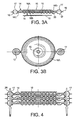
figures 3A et 3B , une coupe et une vue de dessus de deux plaques bipolaires selon une première réalisation de l'invention ; -
figure 4 , en coupe, trois étages de piles à combustible utilisant des plaques bipolaires selon la réalisation représentée auxfigures 3A et 3B ; -
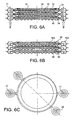
figures 5A, 5B et 5C , en coupe et en vue de dessus, trois étages d'un empilement de piles à combustible utilisant des plaques bipolaires selon l'invention dans une deuxième réalisation de celles-ci ; -
figures 6A, 6B et 6C , en coupe et en vue de dessus, trois étages d'un empilement de piles à combustible utilisant une plaque bipolaire dans une troisième réalisation de l'invention. - En référence aux
figures 2A et 2B , la géométrie des éléments de base 10 et des plaques bipolaires 12 selon l'invention est circulaire. Des électrodes de chaque élément de base 10 sont alimentées respectivement par le dessus et le dessous au moyen chacune d'une plaque bipolaire 12 de même géométrie circulaire. Des alimentations en combustible et carburant, à savoir de l'hydrogène ou de l'air, sont faites depuis l'extérieur de l'assemblage et amenées au centre de chaque électrode au moyen d'une plaque bipolaire 12. Par exemple, l'hydrogène alimente une électrode placée au-dessus de la plaque bipolaire 12 concernée tandis que l'air alimente l'électrode placée en dessous de cette plaque bipolaire 12. - Par ce principe, la difficulté de devoir réaliser l'étanchéité d'un éventuel puits central d'alimentation en air ou en hydrogène est évitée. Les éléments de base 10 et les plaques bipolaires 12 peuvent être du même diamètre.
- En référence aux
figures 3A ou 3B , chaque plaque bipolaire selon l'invention est constituée d'un unique séparateur 20, métallique et rigide, constitué d'une tôle plane et permettant d'assurer la rigidité mécanique de l'ensemble. Celui-ci est pris en sandwich entre deux distributeurs 14 métalliques et rigides, constitués chacune d'une tôle ondulée qui peut être obtenue, par exemple, par emboutissage. Ainsi, le distributeur 14 possède sur chaque face des canaux 16A et 16B correspondant respectivement aux séparations existants entre les parties du canal formé sur l'autre face. En d'autres termes, la tôle ondulée constituant chaque distributeur 14 a des faces ayant chacune une forme complémentaire. Ceci présente un grand avantage qui est de pouvoir constituer tous les distributeurs par un seul type de distributeur. En d'autres termes, une unique sorte de pièce est conçue pour réaliser ces éléments. - D'autre part, les canaux 16A et 16B sont constitués chacun d'un seul canal, par exemple disposé en spirale autour du centre et aboutissant à ce dernier. La
figure 3B montre une telle configuration. Or, chaque séparateur 14 possède, en son centre, un trou de distribution 15 auquel sont raccordés les deux canaux 16A et 16B. Du fait de cette communication, chaque distributeur possède en fait qu'un seul canal traversant sa paroi. Un des deux canaux, en l'occurrence le canal 16B, possède une extrémité périphérique 16C débouchant dans un évidement périphérique 18 du distributeur. De son côté, l'autre canal 16A possède une extrémité opposée 16D débouchant à l'extérieur de l'empilement. On conçoit que, une fois ainsi empilé entre un élément de base 10 et un séparateur 20, chaque unique canal composé de la succession de canaux 16A et 16B puisse faire circuler un gaz provenant de l'évidement périphérique 18 et étant évacué vers l'extérieur par l'extrémité 16D du canal 16A débouchant vers l'extérieur. Comme, au niveau de chaque évidemment 18, se trouve un trou d'alimentation 17, on comprend que, soit de l'air, soit de l'hydrogène, puisse être envoyé contre chaque face d'un élément de base 10 de la pile à combustible ainsi constitué. Le fonctionnement de la pile se complète par un collectage de courant électrique non représenté et disposé au voisinage d'une des deux électrodes. Les deux distributeurs 14 peuvent être assemblés par brasage, de façon périphérique, autour du séparateur 20 qui est alors enfermé. Le trou de distribution 15 qui permet au canal de passer d'un côté à l'autre du distributeur est central. En effet, cela permet d'utiliser toute la surface réactive de l'élément de base 10 (électrode/membrane/électrode). Lors du fonctionnement, il y a dégagement de chaleur. Par une alimentation centrale, on conserve la symétrie de révolution même pour la cartographie de température (plus chaud au centre et plus froid vers l'extérieur,de manière concentrique). - Afin de constituer un empilement permettant d'augmenter la puissance d'une pile à combustible, il suffit d'empiler les différents sous-ensembles ainsi constitués d'une plaque bipolaire et d'un élément de base électrode/membrane/électrode, les uns sur les autres. Les puits d'alimentation en air ou en hydrogène se constituent ainsi au fur et à mesure du montage, par superposition des trous d'alimentation 17.
- En référence à la
figure 4 , un tel empilement constitué d'une série d'éléments de base électrode/membrane/électrode 10 et de plaques bipolaires, telles qu'elles viennent d'être décrites, doit posséder une certaine étanchéité. - A cet effet, au niveau des trous d'alimentation 17, un joint d'étanchéité 26 est placé autour du trou d'alimentation 17 sur la face de la plaque bipolaire 14 qui se trouve en regard d'un élément de base électrode/membrane/électrode 10. Un tel joint 26 peut être en mica ou être déposé par plasma. On remarque que si des fuites se produisent à ce niveau, elles sont localisées dans une zone externe à la partie active ou fonctionnelle de la pile à combustible et n'ont donc pas d'impact sur l'intégrité de l'élément de base électrode/membrane/électrole 10. De plus, ce type de joint 26 assure à la fois l'isolation électrique et l'étanchéité par rapport au gaz.
- En référence aux
figures 5A, 5B et 5C , une deuxième réalisation du concept de pile à combustible selon l'invention prévoit que les gaz carburant et combustible ainsi que leur produit résiduel, après réaction, soient récupérés, c'est-à-dire collectés, de façon séparée, l'étanchéité étant assurée entre la zone de fonctionnement de la pile à combustible et l'extérieur de l'empilement. Lafigure 5C montre, non seulement les trous d'alimentation 17, mais également les trous d'évacuation 28 configurés de façon analogue et reliés chacun à la sortie d'une canalisation de chaque étage constitué par les deux côtés d'un distributeur 24. - Contrairement à la réalisation précédente, aucune issue n'est possible en périphérie pour les gaz résiduels et le combustible et le carburant à la sortie de la canalisation de distribution. Un anneau de garde 29, constitué par le dernier cercle de la forme spirale de la canalisation, formé par la déformation de ce distributeur 24 et une deuxième extrémité 16E du canal de distribution 16F permettent de relier cette dernière au trou d'évacuation 28. Au niveau de l'anneau de garde 29, un joint est placé sur la surface devant être en contact avec l'élément de base électrode/membrane/électrode 10, de manière à assurer l'étanchéité de l'ensemble de l'empilement. En d'autres termes, un joint est placé sur chaque face de l'élément de base électrode/membrane/électrode 10, dans sa périphérie.
- On peut également envisager de ne récupérer que le combustible et de laisser s'échapper le comburant. Dans ce cas là, les distributeurs d'une même plaque bipolaire sont différents.
- En référence aux
figures 6A, 6B et 6C , une réalisation selon l'invention prévoit de n'utiliser qu'un seul distributeur tel qu'il vient d'être décrit. Dans ce cas, on utilise un deuxième type de distributeur 30 constitués d'un support poreux, de manière à ce que le gaz combustible ou carburant puisse circuler sur tout le volume de ce support poreux et être en contact avec une électrode de l'élément de base 10 électrode/membrane/électrode. Ce support poreux 30 se complète d'un cadre périphérique 31 qui a la même forme, au niveau des trous d'alimentation 17 et de sortie 28. Dans ce cas, le séparateur 40 possède un canal d'évacuation 34 du canal de distribution 16G vers le puits d'évacuation. - Ce support poreux 30, est soit assemblé sur le séparateur 20, soit déposé par une technique de revêtement. Le matériau est soit un conducteur électronique soit un conducteur mixte, c'est-à-dire électronique et ionique.
- La séparation du compartiment anodique avec l'extérieur et du compartiment cathodique avec l'extérieur est assurée dans ce cas également au moyen d'un joint isolant électrique entre deux plaques bipolaires au niveau de la zone 33, c'est-à-dire à l'endroit de la jonction entre le support poreux 30 et son cadre 31. Cette réalisation permet d'assurer un très bon contact électrique entre la plaque bipolaire et le support poreux 30 qui la constitue partiellement et sur lequel est déposé une électrode de l'élément de base 10 électrode/membrane/électrode soit directement sur l'électrolyte au cas où se support poreux 30 est constitué à la fois d'un conducteur ionique et électronique.
- Dans cette réalisation, le séparateur 20 possède un canal d'alimentation 32 débouchant vers le centre de la plaque bipolaire et vers un trou d'alimentation 17.
- Dans les réalisations proposées selon l'invention, on permet de s'affranchir des problèmes d'étanchéité au niveau de l'hydrogène tout en gardant un montage simplifié de l'empilement.
- Les zones d'étanchéité sont en parties déportées par rapport aux zones fonctionnelles de la pile. Le nombre d'entrées et de sortie peut être réduit au nombre d'une entrée et d'une sortie par compartiment.
- La forme spirale pour la canalisation de distribution a été proposée dans cette réalisation, d'autres formes peuvent être envisagées, dès l'instant que le principe de constitution des puits d'alimentation et de sortie et de séparation d'étanchéité pour les gaz de sortie est conservé.
- Ce concept permet de réduire substantiellement les coûts de fabrication d'une plaque bipolaire. En effet, dans la première réalisation, la plaque bipolaire n'est constituée que de deux éléments différents, à savoir un séparateur et deux distributeurs. Ces derniers peuvent être obtenus facilement par emboutissage, ce qui réduit considération les coûts de fabrication.
- L'invention s'applique particulièrement aux piles du type SOFC (Solid Oxide Fuell Cell).
- Le concept est indépendant de la nature du combustible utilisé du côté anodique (hydrogène, méthane, hydrocarbure, etc.) et peut fonctionner avec introduction d'air ou d'oxygène côté cathodique.
- Le principe est également utilisé sur des piles à combustible du type PCFC (Proton Ceramic Fuell, Cell).
- Enfin, en envisageant de mettre en oeuvre le fonctionnement inverse d'une pile à combustible, il est possible de concevoir un électrolyseur haute température pour produire de l'hydrogène par dissociation de molécules d'eau sous courant électrique. Néanmoins, seule la version avec séparation des gaz en sortie est applicable à un tel électrolyseur. On note que à la fois le mode "anode oxygène" et le mode "anode dépolarisée" peut être mis en oeuvre, soit par un mode allo-thermique, soit par un mode auto-thermique.
Claims (10)
- Plaque bipolaire pour pile à combustible destinée à être montée entre deux éléments de base (10) électrode/membrane/électrode, possédant au moins deux trous d'alimentation (17) placés de façon périphérique, caractérisée en ce qu'elle est constituée d'un :- un séparateur (20) rigide, métallique ; et- au moins un premier distributeur (14) rigide, métallique en tôle déformée, de façon à ce que sa forme constitue une canalisation de distribution (16A, 16B) de chaque côté de cette tôle, et possédant un trou de distribution (15) auquel aboutit une première extrémité de chaque canalisation de distribution (16A, 16B), de façon à ne former qu'une seule canalisation traversant le distributeur (14).
- Plaque bipolaire selon la revendication 1, caractérisée en ce que le trou de distribution (15) est central.
- Plaque bipolaire selon la revendication 1, caractérisée en ce qu'elle comprend au moins deux distributeurs (14) placés chacun d'un côté du séparateur (20).
- Plaque bipolaire selon la revendication 3, caractérisée en ce que les deux distributeurs (14) sont identiques.
- Plaque bipolaire selon la revendication 1, caractérisée en ce qu'une deuxième extrémité (16C) d'au moins une canalisation (16A, 16B) débouche à l'extérieur de la plaque bipolaire ainsi formée.
- Plaque bipolaire selon la revendication 1 ou 5, caractérisée en ce qu'une deuxième extrémité (16E) d'au moins une canalisation de distribution (16F) est en communication avec un trou d'évacuation (17) périphérique.
- Plaque bipolaire selon la revendication 5, caractérisée en ce qu'il comprend un anneau de garde (29) constituant la périphérie de la canalisation de distribution (16F).
- Plaque bipolaire selon la revendication 1, caractérisée en ce qu'il comprend un deuxième distributeur d'un deuxième type constitué d'un cadre métallique (31) en forme de cuvette au milieu duquel se trouve un support poreux (30), le séparateur (20) possédant un passage de sortie périphérique (32) reliant le support poreux (30) à un trou d'alimentation (17) périphérique et un canal d'évacuation (34) reliant le canal de distribution (16G) à un trou d'évacuation (28).
- Pile à combustible constituée d'un empilement de plusieurs plaques bipolaires selon l'une quelconque des revendications précédentes, ainsi que d'éléments de base (10) électrode/membrane/électrode.
- Pile à combustible selon la revendication 9, caractérisée en ce qu'on utilise au moins un joint d'étanchéité électrique et gazeuse (26) entre les plaques bipolaires et les éléments de base (10) électrode/membrane/électrode.
Applications Claiming Priority (2)
| Application Number | Priority Date | Filing Date | Title |
|---|---|---|---|
| FR0550704A FR2883419B1 (fr) | 2005-03-18 | 2005-03-18 | Plaque bipolaire pour pile a combustible a tole de distribution metallique deformee |
| PCT/FR2006/050222 WO2006097658A2 (fr) | 2005-03-18 | 2006-03-14 | Plaque bipolaire pour pile a combustible a tole de distribution metallique deformee |
Publications (2)
| Publication Number | Publication Date |
|---|---|
| EP1859500A2 EP1859500A2 (fr) | 2007-11-28 |
| EP1859500B1 true EP1859500B1 (fr) | 2010-09-22 |
Family
ID=35134144
Family Applications (1)
| Application Number | Title | Priority Date | Filing Date |
|---|---|---|---|
| EP06726245A Expired - Lifetime EP1859500B1 (fr) | 2005-03-18 | 2006-03-14 | Plaque bipolaire pour pile a combustible a tole de distribution metallique deformee |
Country Status (8)
| Country | Link |
|---|---|
| US (1) | US8007955B2 (fr) |
| EP (1) | EP1859500B1 (fr) |
| JP (1) | JP5345380B2 (fr) |
| AT (1) | ATE482485T1 (fr) |
| DE (1) | DE602006017041D1 (fr) |
| ES (1) | ES2353465T3 (fr) |
| FR (1) | FR2883419B1 (fr) |
| WO (1) | WO2006097658A2 (fr) |
Families Citing this family (8)
| Publication number | Priority date | Publication date | Assignee | Title |
|---|---|---|---|---|
| ES2315126B1 (es) * | 2006-10-06 | 2010-01-08 | Consejo Superior Investig. Cientificas | Placa bipolar para distribucion homogenea del flujo en pilas de combustible. |
| FR2921390B1 (fr) * | 2007-09-25 | 2010-12-03 | Commissariat Energie Atomique | Electrolyseur haute temperature a dispositif d'homogeneisation de la temperature. |
| DE102008052945B4 (de) * | 2008-10-23 | 2014-06-12 | Staxera Gmbh | Brennstoffzellenstapel und Verfahren zu dessen Herstellung |
| US8137856B2 (en) * | 2009-02-13 | 2012-03-20 | Hitachi, Ltd. | Fuel cell |
| CN109841864B (zh) * | 2017-11-29 | 2022-02-18 | 中国科学院青岛生物能源与过程研究所 | 一种质子交换膜燃料电池双极板立体化流场 |
| CN112038657B (zh) * | 2020-09-29 | 2024-10-15 | 西安热工研究院有限公司 | 一种螺旋通道燃料电池双极板 |
| CN113140748B (zh) * | 2021-04-20 | 2024-09-27 | 大连海事大学 | 一种带螺旋的斗状燃料电池双极板 |
| US20250273702A1 (en) * | 2022-04-18 | 2025-08-28 | ZeroAvia, Inc. | Bipolar plate of fuel cell and method for operating it |
Family Cites Families (13)
| Publication number | Priority date | Publication date | Assignee | Title |
|---|---|---|---|---|
| JPH0269464U (fr) * | 1988-11-15 | 1990-05-25 | ||
| EP0378812A1 (fr) * | 1989-01-18 | 1990-07-25 | Asea Brown Boveri Ag | Agencement de cellules à combustible à base d'un électrolyte solide constitué d'oxyde de zircon stabilisé fonctionnant à haute température pour obtenir une puissance maximale |
| DE59409325D1 (de) * | 1994-11-23 | 2000-06-08 | Sulzer Hexis Ag Winterthur | Hochtemperatur-Brennstoffzelle mit chromhaltigen Verbindungselementen zwischen elektrochemisch aktiven Platten |
| US5981098A (en) * | 1997-08-28 | 1999-11-09 | Plug Power, L.L.C. | Fluid flow plate for decreased density of fuel cell assembly |
| JP2001068132A (ja) * | 1999-08-25 | 2001-03-16 | Tokyo Gas Co Ltd | 集電板およびそれを用いた固体電解質燃料電池 |
| JP2001223014A (ja) * | 2000-02-09 | 2001-08-17 | Mitsubishi Nuclear Fuel Co Ltd | 固体電解質型燃料電池 |
| JP4258985B2 (ja) * | 2001-03-16 | 2009-04-30 | 三菱マテリアル株式会社 | 燃料電池 |
| EP1445814A4 (fr) * | 2001-10-26 | 2006-04-26 | Sumitomo Prec Products Company | Pile a combustible |
| US7201991B2 (en) * | 2002-03-04 | 2007-04-10 | Mitsubishi Materials Corporation | Solid oxide fuel cell and separator |
| JP2003331871A (ja) * | 2002-03-04 | 2003-11-21 | Mitsubishi Materials Corp | 平板型の固体酸化物形燃料電池およびセパレータ |
| WO2003088378A2 (fr) * | 2002-03-26 | 2003-10-23 | The Regents Of The University Of California | Champ de flux ameliore et plaque bipolaire pour pile a combustible |
| JP4404331B2 (ja) * | 2003-02-27 | 2010-01-27 | 住友精密工業株式会社 | 燃料電池 |
| US7829231B2 (en) * | 2005-04-22 | 2010-11-09 | Gm Global Technology Operations, Inc. | Fuel cell design with an integrated heat exchanger and gas humidification unit |
-
2005
- 2005-03-18 FR FR0550704A patent/FR2883419B1/fr not_active Expired - Fee Related
-
2006
- 2006-03-14 WO PCT/FR2006/050222 patent/WO2006097658A2/fr not_active Ceased
- 2006-03-14 JP JP2008501383A patent/JP5345380B2/ja not_active Expired - Fee Related
- 2006-03-14 EP EP06726245A patent/EP1859500B1/fr not_active Expired - Lifetime
- 2006-03-14 AT AT06726245T patent/ATE482485T1/de not_active IP Right Cessation
- 2006-03-14 DE DE602006017041T patent/DE602006017041D1/de not_active Expired - Lifetime
- 2006-03-14 US US11/886,172 patent/US8007955B2/en not_active Expired - Fee Related
- 2006-03-14 ES ES06726245T patent/ES2353465T3/es not_active Expired - Lifetime
Also Published As
| Publication number | Publication date |
|---|---|
| JP2008533677A (ja) | 2008-08-21 |
| FR2883419A1 (fr) | 2006-09-22 |
| WO2006097658A3 (fr) | 2007-02-15 |
| WO2006097658A2 (fr) | 2006-09-21 |
| EP1859500A2 (fr) | 2007-11-28 |
| US20080145740A1 (en) | 2008-06-19 |
| JP5345380B2 (ja) | 2013-11-20 |
| FR2883419B1 (fr) | 2007-04-20 |
| DE602006017041D1 (de) | 2010-11-04 |
| US8007955B2 (en) | 2011-08-30 |
| ATE482485T1 (de) | 2010-10-15 |
| ES2353465T3 (es) | 2011-03-02 |
Similar Documents
| Publication | Publication Date | Title |
|---|---|---|
| EP1807895B1 (fr) | Module de pile a combustible a interconnecteurs flexibles | |
| FR2810795A1 (fr) | Plaque bipolaire a deux plaques metalliques pour pile a combustible et son procede de fabrication | |
| FR2819107A1 (fr) | Procede de fabrication d'un assemblage d'elements de base pour un etage de pile a combustible | |
| FR2852736A1 (fr) | Pile a combustible planaire et procede de fabrication d'une telle pile. | |
| WO2006097658A2 (fr) | Plaque bipolaire pour pile a combustible a tole de distribution metallique deformee | |
| EP2707920B1 (fr) | Pile a combustible avec collecteurs a joints injecteurs individuels | |
| FR3079676A1 (fr) | Plaque bipolaire a canaux ondules | |
| EP1358691B1 (fr) | Procede de fabrication de plaques bipolaires legeres pour piles a combustible | |
| CA2560761C (fr) | Pile a combustible a electrolyte solide a structure etanche | |
| FR2819343A1 (fr) | Pile a combustible equipee de plaques polaires identiques et a circulation interne de combustible et de refrigerant | |
| EP1749323B1 (fr) | Cellule de pile a combustible a electrolyte solide | |
| EP1900050B1 (fr) | Plaque bipolaire pour pile a combustible comprenant des nervures d'etancheite | |
| EP1938409B1 (fr) | Module tubulaire de pile a combustible et son dispositif pour joint d'etancheite | |
| WO2009030648A1 (fr) | Module coaxial de pile a combustible ou electrolyseur a interconnecteurs a billes | |
| EP2329557B1 (fr) | Brides de serrage multifonctions pour pile a combustible | |
| EP1941571B1 (fr) | Empilement etanche de pile a combustible | |
| EP1807897B1 (fr) | Module de pile a combustible, son procede de fabrication et unite contenant plusieurs de ceux-ci | |
| FR2816448A1 (fr) | Plaque bipolaire a deux plaques metalliques et structures gaufrees pour pile a combustible | |
| EP4567938A1 (fr) | Réacteur d'électrolyse ou de co-électrolyse (soec) ou pile à combustible (sofc) à empilement de cellules électrochimiques intégrant des éléments de renfort mécanique à rigidité variable avec la température |
Legal Events
| Date | Code | Title | Description |
|---|---|---|---|
| PUAI | Public reference made under article 153(3) epc to a published international application that has entered the european phase |
Free format text: ORIGINAL CODE: 0009012 |
|
| 17P | Request for examination filed |
Effective date: 20070813 |
|
| AK | Designated contracting states |
Kind code of ref document: A2 Designated state(s): AT BE BG CH CY CZ DE DK EE ES FI FR GB GR HU IE IS IT LI LT LU LV MC NL PL PT RO SE SI SK TR |
|
| DAX | Request for extension of the european patent (deleted) | ||
| GRAP | Despatch of communication of intention to grant a patent |
Free format text: ORIGINAL CODE: EPIDOSNIGR1 |
|
| RAP1 | Party data changed (applicant data changed or rights of an application transferred) |
Owner name: COMMISSARIAT A L'ENERGIE ATOMIQUE ET AUX ENERGIES |
|
| GRAS | Grant fee paid |
Free format text: ORIGINAL CODE: EPIDOSNIGR3 |
|
| GRAA | (expected) grant |
Free format text: ORIGINAL CODE: 0009210 |
|
| AK | Designated contracting states |
Kind code of ref document: B1 Designated state(s): AT BE BG CH CY CZ DE DK EE ES FI FR GB GR HU IE IS IT LI LT LU LV MC NL PL PT RO SE SI SK TR |
|
| REG | Reference to a national code |
Ref country code: GB Ref legal event code: FG4D Free format text: NOT ENGLISH |
|
| REG | Reference to a national code |
Ref country code: CH Ref legal event code: EP |
|
| REG | Reference to a national code |
Ref country code: IE Ref legal event code: FG4D Free format text: LANGUAGE OF EP DOCUMENT: FRENCH |
|
| REF | Corresponds to: |
Ref document number: 602006017041 Country of ref document: DE Date of ref document: 20101104 Kind code of ref document: P |
|
| REG | Reference to a national code |
Ref country code: NL Ref legal event code: T3 |
|
| PG25 | Lapsed in a contracting state [announced via postgrant information from national office to epo] |
Ref country code: AT Free format text: LAPSE BECAUSE OF FAILURE TO SUBMIT A TRANSLATION OF THE DESCRIPTION OR TO PAY THE FEE WITHIN THE PRESCRIBED TIME-LIMIT Effective date: 20100922 Ref country code: LT Free format text: LAPSE BECAUSE OF FAILURE TO SUBMIT A TRANSLATION OF THE DESCRIPTION OR TO PAY THE FEE WITHIN THE PRESCRIBED TIME-LIMIT Effective date: 20100922 |
|
| LTIE | Lt: invalidation of european patent or patent extension |
Effective date: 20100922 |
|
| PG25 | Lapsed in a contracting state [announced via postgrant information from national office to epo] |
Ref country code: SI Free format text: LAPSE BECAUSE OF FAILURE TO SUBMIT A TRANSLATION OF THE DESCRIPTION OR TO PAY THE FEE WITHIN THE PRESCRIBED TIME-LIMIT Effective date: 20100922 Ref country code: PL Free format text: LAPSE BECAUSE OF FAILURE TO SUBMIT A TRANSLATION OF THE DESCRIPTION OR TO PAY THE FEE WITHIN THE PRESCRIBED TIME-LIMIT Effective date: 20100922 |
|
| REG | Reference to a national code |
Ref country code: ES Ref legal event code: FG2A Effective date: 20110218 |
|
| PG25 | Lapsed in a contracting state [announced via postgrant information from national office to epo] |
Ref country code: LV Free format text: LAPSE BECAUSE OF FAILURE TO SUBMIT A TRANSLATION OF THE DESCRIPTION OR TO PAY THE FEE WITHIN THE PRESCRIBED TIME-LIMIT Effective date: 20100922 Ref country code: SE Free format text: LAPSE BECAUSE OF FAILURE TO SUBMIT A TRANSLATION OF THE DESCRIPTION OR TO PAY THE FEE WITHIN THE PRESCRIBED TIME-LIMIT Effective date: 20100922 Ref country code: GR Free format text: LAPSE BECAUSE OF FAILURE TO SUBMIT A TRANSLATION OF THE DESCRIPTION OR TO PAY THE FEE WITHIN THE PRESCRIBED TIME-LIMIT Effective date: 20101223 |
|
| REG | Reference to a national code |
Ref country code: IE Ref legal event code: FD4D |
|
| PG25 | Lapsed in a contracting state [announced via postgrant information from national office to epo] |
Ref country code: IE Free format text: LAPSE BECAUSE OF FAILURE TO SUBMIT A TRANSLATION OF THE DESCRIPTION OR TO PAY THE FEE WITHIN THE PRESCRIBED TIME-LIMIT Effective date: 20100922 |
|
| PG25 | Lapsed in a contracting state [announced via postgrant information from national office to epo] |
Ref country code: EE Free format text: LAPSE BECAUSE OF FAILURE TO SUBMIT A TRANSLATION OF THE DESCRIPTION OR TO PAY THE FEE WITHIN THE PRESCRIBED TIME-LIMIT Effective date: 20100922 Ref country code: SK Free format text: LAPSE BECAUSE OF FAILURE TO SUBMIT A TRANSLATION OF THE DESCRIPTION OR TO PAY THE FEE WITHIN THE PRESCRIBED TIME-LIMIT Effective date: 20100922 Ref country code: CZ Free format text: LAPSE BECAUSE OF FAILURE TO SUBMIT A TRANSLATION OF THE DESCRIPTION OR TO PAY THE FEE WITHIN THE PRESCRIBED TIME-LIMIT Effective date: 20100922 Ref country code: RO Free format text: LAPSE BECAUSE OF FAILURE TO SUBMIT A TRANSLATION OF THE DESCRIPTION OR TO PAY THE FEE WITHIN THE PRESCRIBED TIME-LIMIT Effective date: 20100922 Ref country code: IS Free format text: LAPSE BECAUSE OF FAILURE TO SUBMIT A TRANSLATION OF THE DESCRIPTION OR TO PAY THE FEE WITHIN THE PRESCRIBED TIME-LIMIT Effective date: 20110122 Ref country code: PT Free format text: LAPSE BECAUSE OF FAILURE TO SUBMIT A TRANSLATION OF THE DESCRIPTION OR TO PAY THE FEE WITHIN THE PRESCRIBED TIME-LIMIT Effective date: 20110124 |
|
| PLBE | No opposition filed within time limit |
Free format text: ORIGINAL CODE: 0009261 |
|
| STAA | Information on the status of an ep patent application or granted ep patent |
Free format text: STATUS: NO OPPOSITION FILED WITHIN TIME LIMIT |
|
| 26N | No opposition filed |
Effective date: 20110623 |
|
| PG25 | Lapsed in a contracting state [announced via postgrant information from national office to epo] |
Ref country code: DK Free format text: LAPSE BECAUSE OF FAILURE TO SUBMIT A TRANSLATION OF THE DESCRIPTION OR TO PAY THE FEE WITHIN THE PRESCRIBED TIME-LIMIT Effective date: 20100922 |
|
| BERE | Be: lapsed |
Owner name: COMMISSARIAT A L'ENERGIE ATOMIQUE ET AUX ENERGIES Effective date: 20110331 |
|
| REG | Reference to a national code |
Ref country code: DE Ref legal event code: R097 Ref document number: 602006017041 Country of ref document: DE Effective date: 20110623 |
|
| PG25 | Lapsed in a contracting state [announced via postgrant information from national office to epo] |
Ref country code: MC Free format text: LAPSE BECAUSE OF NON-PAYMENT OF DUE FEES Effective date: 20110331 |
|
| REG | Reference to a national code |
Ref country code: CH Ref legal event code: PL |
|
| PG25 | Lapsed in a contracting state [announced via postgrant information from national office to epo] |
Ref country code: BE Free format text: LAPSE BECAUSE OF NON-PAYMENT OF DUE FEES Effective date: 20110331 |
|
| PG25 | Lapsed in a contracting state [announced via postgrant information from national office to epo] |
Ref country code: CH Free format text: LAPSE BECAUSE OF NON-PAYMENT OF DUE FEES Effective date: 20110331 Ref country code: LI Free format text: LAPSE BECAUSE OF NON-PAYMENT OF DUE FEES Effective date: 20110331 |
|
| PG25 | Lapsed in a contracting state [announced via postgrant information from national office to epo] |
Ref country code: LU Free format text: LAPSE BECAUSE OF NON-PAYMENT OF DUE FEES Effective date: 20110314 Ref country code: CY Free format text: LAPSE BECAUSE OF FAILURE TO SUBMIT A TRANSLATION OF THE DESCRIPTION OR TO PAY THE FEE WITHIN THE PRESCRIBED TIME-LIMIT Effective date: 20100922 |
|
| PG25 | Lapsed in a contracting state [announced via postgrant information from national office to epo] |
Ref country code: TR Free format text: LAPSE BECAUSE OF FAILURE TO SUBMIT A TRANSLATION OF THE DESCRIPTION OR TO PAY THE FEE WITHIN THE PRESCRIBED TIME-LIMIT Effective date: 20100922 Ref country code: BG Free format text: LAPSE BECAUSE OF FAILURE TO SUBMIT A TRANSLATION OF THE DESCRIPTION OR TO PAY THE FEE WITHIN THE PRESCRIBED TIME-LIMIT Effective date: 20101222 |
|
| PG25 | Lapsed in a contracting state [announced via postgrant information from national office to epo] |
Ref country code: HU Free format text: LAPSE BECAUSE OF FAILURE TO SUBMIT A TRANSLATION OF THE DESCRIPTION OR TO PAY THE FEE WITHIN THE PRESCRIBED TIME-LIMIT Effective date: 20100922 |
|
| REG | Reference to a national code |
Ref country code: FR Ref legal event code: PLFP Year of fee payment: 11 |
|
| REG | Reference to a national code |
Ref country code: FR Ref legal event code: PLFP Year of fee payment: 12 |
|
| REG | Reference to a national code |
Ref country code: FR Ref legal event code: PLFP Year of fee payment: 13 |
|
| PGFP | Annual fee paid to national office [announced via postgrant information from national office to epo] |
Ref country code: NL Payment date: 20180214 Year of fee payment: 13 |
|
| PGFP | Annual fee paid to national office [announced via postgrant information from national office to epo] |
Ref country code: DE Payment date: 20180309 Year of fee payment: 13 Ref country code: GB Payment date: 20180316 Year of fee payment: 13 Ref country code: FI Payment date: 20180220 Year of fee payment: 13 |
|
| PGFP | Annual fee paid to national office [announced via postgrant information from national office to epo] |
Ref country code: IT Payment date: 20180309 Year of fee payment: 13 Ref country code: FR Payment date: 20180329 Year of fee payment: 13 |
|
| PGFP | Annual fee paid to national office [announced via postgrant information from national office to epo] |
Ref country code: ES Payment date: 20180427 Year of fee payment: 13 |
|
| REG | Reference to a national code |
Ref country code: DE Ref legal event code: R119 Ref document number: 602006017041 Country of ref document: DE |
|
| PG25 | Lapsed in a contracting state [announced via postgrant information from national office to epo] |
Ref country code: FI Free format text: LAPSE BECAUSE OF NON-PAYMENT OF DUE FEES Effective date: 20190314 |
|
| REG | Reference to a national code |
Ref country code: NL Ref legal event code: MM Effective date: 20190401 |
|
| GBPC | Gb: european patent ceased through non-payment of renewal fee |
Effective date: 20190314 |
|
| PG25 | Lapsed in a contracting state [announced via postgrant information from national office to epo] |
Ref country code: DE Free format text: LAPSE BECAUSE OF NON-PAYMENT OF DUE FEES Effective date: 20191001 Ref country code: NL Free format text: LAPSE BECAUSE OF NON-PAYMENT OF DUE FEES Effective date: 20190401 Ref country code: GB Free format text: LAPSE BECAUSE OF NON-PAYMENT OF DUE FEES Effective date: 20190314 |
|
| PG25 | Lapsed in a contracting state [announced via postgrant information from national office to epo] |
Ref country code: FR Free format text: LAPSE BECAUSE OF NON-PAYMENT OF DUE FEES Effective date: 20190331 Ref country code: IT Free format text: LAPSE BECAUSE OF NON-PAYMENT OF DUE FEES Effective date: 20190314 |
|
| REG | Reference to a national code |
Ref country code: ES Ref legal event code: FD2A Effective date: 20200724 |
|
| PG25 | Lapsed in a contracting state [announced via postgrant information from national office to epo] |
Ref country code: ES Free format text: LAPSE BECAUSE OF NON-PAYMENT OF DUE FEES Effective date: 20190315 |