EP1858459B1 - Apparatus for sealing an opening in a human or animal eye - Google Patents
Apparatus for sealing an opening in a human or animal eye Download PDFInfo
- Publication number
- EP1858459B1 EP1858459B1 EP06722984A EP06722984A EP1858459B1 EP 1858459 B1 EP1858459 B1 EP 1858459B1 EP 06722984 A EP06722984 A EP 06722984A EP 06722984 A EP06722984 A EP 06722984A EP 1858459 B1 EP1858459 B1 EP 1858459B1
- Authority
- EP
- European Patent Office
- Prior art keywords
- sealing
- region
- surgical instrument
- passageway
- opening
- Prior art date
- Legal status (The legal status is an assumption and is not a legal conclusion. Google has not performed a legal analysis and makes no representation as to the accuracy of the status listed.)
- Active
Links
- 238000007789 sealing Methods 0.000 title claims abstract description 128
- 241001465754 Metazoa Species 0.000 title claims abstract description 5
- 230000002262 irrigation Effects 0.000 claims description 27
- 238000003973 irrigation Methods 0.000 claims description 27
- 210000004087 cornea Anatomy 0.000 claims description 19
- 239000012530 fluid Substances 0.000 claims description 19
- 210000003786 sclera Anatomy 0.000 claims description 15
- 229920001971 elastomer Polymers 0.000 claims description 8
- 239000000463 material Substances 0.000 claims description 7
- 241001474791 Proboscis Species 0.000 claims description 5
- KPUWHANPEXNPJT-UHFFFAOYSA-N disiloxane Chemical class [SiH3]O[SiH3] KPUWHANPEXNPJT-UHFFFAOYSA-N 0.000 claims description 5
- 239000000806 elastomer Substances 0.000 claims description 5
- 230000002093 peripheral effect Effects 0.000 claims description 5
- 229920003052 natural elastomer Polymers 0.000 claims description 3
- 229920001194 natural rubber Polymers 0.000 claims description 3
- 239000005060 rubber Substances 0.000 claims description 3
- 239000013013 elastic material Substances 0.000 claims description 2
- 229920003051 synthetic elastomer Polymers 0.000 claims description 2
- 239000005061 synthetic rubber Substances 0.000 claims description 2
- 244000043261 Hevea brasiliensis Species 0.000 claims 2
- 210000001508 eye Anatomy 0.000 description 65
- 210000001519 tissue Anatomy 0.000 description 32
- 210000003491 skin Anatomy 0.000 description 15
- 238000002604 ultrasonography Methods 0.000 description 13
- 238000001356 surgical procedure Methods 0.000 description 11
- 238000000034 method Methods 0.000 description 10
- 239000007788 liquid Substances 0.000 description 9
- 239000000835 fiber Substances 0.000 description 8
- 230000007704 transition Effects 0.000 description 8
- 208000002177 Cataract Diseases 0.000 description 7
- 210000001525 retina Anatomy 0.000 description 5
- 210000004127 vitreous body Anatomy 0.000 description 5
- 210000002159 anterior chamber Anatomy 0.000 description 4
- 230000006378 damage Effects 0.000 description 4
- 238000000605 extraction Methods 0.000 description 4
- 229920001296 polysiloxane Polymers 0.000 description 4
- 210000004207 dermis Anatomy 0.000 description 3
- 238000003780 insertion Methods 0.000 description 3
- 230000037431 insertion Effects 0.000 description 3
- 230000003287 optical effect Effects 0.000 description 3
- 210000001747 pupil Anatomy 0.000 description 3
- 206010038848 Retinal detachment Diseases 0.000 description 2
- 208000027418 Wounds and injury Diseases 0.000 description 2
- 210000004556 brain Anatomy 0.000 description 2
- 210000005252 bulbus oculi Anatomy 0.000 description 2
- 230000001886 ciliary effect Effects 0.000 description 2
- 238000013016 damping Methods 0.000 description 2
- 230000001419 dependent effect Effects 0.000 description 2
- 238000011010 flushing procedure Methods 0.000 description 2
- 239000011521 glass Substances 0.000 description 2
- 230000004305 hyperopia Effects 0.000 description 2
- 201000006318 hyperopia Diseases 0.000 description 2
- 230000004410 intraocular pressure Effects 0.000 description 2
- 208000001491 myopia Diseases 0.000 description 2
- 230000004379 myopia Effects 0.000 description 2
- 210000001328 optic nerve Anatomy 0.000 description 2
- 238000012634 optical imaging Methods 0.000 description 2
- 229920003229 poly(methyl methacrylate) Polymers 0.000 description 2
- 239000004926 polymethyl methacrylate Substances 0.000 description 2
- 230000035939 shock Effects 0.000 description 2
- 229920002379 silicone rubber Polymers 0.000 description 2
- 239000004945 silicone rubber Substances 0.000 description 2
- 230000000451 tissue damage Effects 0.000 description 2
- 239000010936 titanium Substances 0.000 description 2
- XLYOFNOQVPJJNP-UHFFFAOYSA-N water Substances O XLYOFNOQVPJJNP-UHFFFAOYSA-N 0.000 description 2
- 241000459479 Capsula Species 0.000 description 1
- 102000008186 Collagen Human genes 0.000 description 1
- 108010035532 Collagen Proteins 0.000 description 1
- 206010020675 Hypermetropia Diseases 0.000 description 1
- 206010030113 Oedema Diseases 0.000 description 1
- 208000002847 Surgical Wound Diseases 0.000 description 1
- RTAQQCXQSZGOHL-UHFFFAOYSA-N Titanium Chemical compound [Ti] RTAQQCXQSZGOHL-UHFFFAOYSA-N 0.000 description 1
- 206010052428 Wound Diseases 0.000 description 1
- 230000004308 accommodation Effects 0.000 description 1
- 230000033228 biological regulation Effects 0.000 description 1
- 230000015572 biosynthetic process Effects 0.000 description 1
- 239000002775 capsule Substances 0.000 description 1
- 230000015556 catabolic process Effects 0.000 description 1
- 230000005779 cell damage Effects 0.000 description 1
- 208000037887 cell injury Diseases 0.000 description 1
- 238000004140 cleaning Methods 0.000 description 1
- 229920001436 collagen Polymers 0.000 description 1
- 238000002485 combustion reaction Methods 0.000 description 1
- 239000012809 cooling fluid Substances 0.000 description 1
- 230000007423 decrease Effects 0.000 description 1
- 230000003247 decreasing effect Effects 0.000 description 1
- 238000011161 development Methods 0.000 description 1
- 230000018109 developmental process Effects 0.000 description 1
- 210000000744 eyelid Anatomy 0.000 description 1
- 239000004744 fabric Substances 0.000 description 1
- 238000002513 implantation Methods 0.000 description 1
- 208000015181 infectious disease Diseases 0.000 description 1
- 238000001802 infusion Methods 0.000 description 1
- 208000014674 injury Diseases 0.000 description 1
- 235000015110 jellies Nutrition 0.000 description 1
- 239000008274 jelly Substances 0.000 description 1
- 210000004072 lung Anatomy 0.000 description 1
- 239000000203 mixture Substances 0.000 description 1
- 210000003205 muscle Anatomy 0.000 description 1
- 230000003387 muscular Effects 0.000 description 1
- 230000010355 oscillation Effects 0.000 description 1
- 238000006303 photolysis reaction Methods 0.000 description 1
- 230000015843 photosynthesis, light reaction Effects 0.000 description 1
- 239000002861 polymer material Substances 0.000 description 1
- 230000001105 regulatory effect Effects 0.000 description 1
- 230000004264 retinal detachment Effects 0.000 description 1
- 230000002441 reversible effect Effects 0.000 description 1
- 210000004894 snout Anatomy 0.000 description 1
- 238000001228 spectrum Methods 0.000 description 1
- 210000002301 subretinal fluid Anatomy 0.000 description 1
- 239000013077 target material Substances 0.000 description 1
- 238000012360 testing method Methods 0.000 description 1
- 229920002725 thermoplastic elastomer Polymers 0.000 description 1
- 231100000827 tissue damage Toxicity 0.000 description 1
- 229910052719 titanium Inorganic materials 0.000 description 1
- 238000001429 visible spectrum Methods 0.000 description 1
- 230000037303 wrinkles Effects 0.000 description 1
Images


Classifications
-
- A—HUMAN NECESSITIES
- A61—MEDICAL OR VETERINARY SCIENCE; HYGIENE
- A61F—FILTERS IMPLANTABLE INTO BLOOD VESSELS; PROSTHESES; DEVICES PROVIDING PATENCY TO, OR PREVENTING COLLAPSING OF, TUBULAR STRUCTURES OF THE BODY, e.g. STENTS; ORTHOPAEDIC, NURSING OR CONTRACEPTIVE DEVICES; FOMENTATION; TREATMENT OR PROTECTION OF EYES OR EARS; BANDAGES, DRESSINGS OR ABSORBENT PADS; FIRST-AID KITS
- A61F9/00—Methods or devices for treatment of the eyes; Devices for putting-in contact lenses; Devices to correct squinting; Apparatus to guide the blind; Protective devices for the eyes, carried on the body or in the hand
- A61F9/007—Methods or devices for eye surgery
Definitions
- the invention relates to a device for sealing an opening in a human or animal eye.
- the human eye or the eyeball comprises an eye compartment surrounded by an outer skin divided into cornea , sclera and sclera , which is divisible in the direction of light into a frontal eye chamber, a posterior chamber and a vitreous cavity in which the vitreous body is arranged.
- the lens Between the anterior chamber of the eye and the vitreous body, the lens ( lens ) is arranged, which is suspended by the zonula fibers on the ciliary muscular system formed on the dermis and can thereby be changed in its convexity and thus its optical focal length (accommodation).
- the vitreous surrounds the retina ( retina ), which is connected to the brain via the optic nerve.
- the cornea forms the front transparent region of the ocular outer skin and forms an optical imaging system together with the transparent liquid in the eye chamber, which consists predominantly of water, the lens and the glass body.
- the image displayed on the retina by this optical imaging system is picked up by the retina and transmitted to the brain via the optic nerve.
- the eye interior there is an eye pressure or internal pressure that is greater than the external pressure or atmospheric pressure (normal pressure). In particular, therefore, the liquid in the eye chamber is under an increased internal pressure.
- the resulting fluid flow and the different pressures usually cause tissue or cell damage, so that the exchange of liquid or, in other words, the volume flow or flow rate of the liquid should be kept as low as possible during the operation.
- a frequently used intraocular surgical procedure is the replacement of a natural eye lens by an artificial (synthetic) eye lens (intraocular lens), which usually consists of a visible spectrum transparent polymer material, in particular acrylic glass (PMMA) or silicone (siloxane elastomer).
- intraocular lens usually consists of a visible spectrum transparent polymer material, in particular acrylic glass (PMMA) or silicone (siloxane elastomer).
- the natural lens is removed from its lens capsule bag ( capsula lensis ) (explantation) and then an intraocular lens is inserted into the remaining lens capsular bag (implantation).
- Explantation of the natural lens is carried out in practice by destruction and discharge of the lens tissue (phakolysis), generally by phacoemulsification, in which the lens is emulsified (liquefied) and aspirated by means of ultrasound or by means of laser light (photolysis) generated shock waves.
- folding lenses or injectable lenses allows for a reduction of the surgical incision to in practice only 2 mm or less even smaller.
- the replacement of natural ophthalmic lenses by a synthetic intraocular lens is currently used primarily for the treatment of cataract (cataract or star). But there are also other applications possible, such as the insertion of an intraocular lens to adjust or correct the optical focal length, for example, myopia (nearsightedness) or farsightedness (hyperopia), or after accidents or injuries to the lens, in which the lens capsular bag itself does not irreparably damaged is.
- US 5,324,281 A is known a surgical instrument in the form of a needle for destroying tissue, which is intended for the photolysical removal of eye cataracts.
- This known instrument has a needle and a laser fiber and a suction channel, each longitudinally and in the interior of the needle to the free end, on.
- a target of titanium (Ti) is arranged at a distance to the free end of the laser fiber, wherein the laser fiber and the target are adjusted to each other, that the laser light from this fiber strikes the target.
- an obliquely and laterally offset tissue receiving opening is provided at the free end of the needle, into which the suction channel opens and which is arranged immediately adjacent to the target and the gap between the laser fiber end and the target.
- a negative pressure (vacuum) is generated in the suction channel, by means of which the tissue to be destroyed is sucked to the tissue receiving opening.
- the target is bombarded with laser pulses from the laser fiber, the laser pulses having sufficient energy to produce an optical breakdown at the surface of the target material.
- a shock wave is generated, which hits the fabric receiving opening on the tissue located there and this breaks into small pieces, which are then sucked through the suction.
- the laser pulses have a pulse duration of 8 ns and a pulse repetition rate of 20 pulses per second and are preferably generated with a neodymium-YAG laser having a wavelength of 1064 nm
- a longitudinally extending flushing channel for guiding flushing fluid through a laterally arranged outlet opening can be provided in the needle.
- US 5,906,611 A is a further education of US 5,324,282 A
- Known instrument known in which the target is formed in a special way step-shaped With a neodymium-YAG laser pulses can be generated with pulse repetition rates between 2 and 50 pulses per second and. Pulse energies between 2 and 15 mJ.
- the pulse duration can be set between 8 and 12 ns.
- the pulse repetition rate is set between 2 and 6 pulses per second and the pulse energy between 6 and 10 mJ.
- For cataract surgery between 200 and 800 pulses or shots are used.
- the needle is inserted into the incision on the eye, the tissue tightly surrounding the needle, thereby sealing the needle against the inner peripheral surface of the outer skin surrounding the aperture.
- ultrasonic instruments In ultrasound phakolysis, ultrasonic instruments are used with an ultrasound needle that is piezoelectrically set in axial oscillations. which is introduced into the eye through the incision. This ultrasound needle vibrates at an ultrasound frequency which is, for example, in the range of kilohertz, for example 40 kHz.
- an ultrasound frequency which is, for example, in the range of kilohertz, for example 40 kHz.
- Such a Ultraschallphakoemulstechnik of ARC Laser GmbH is known under the name "Pharo”.
- the incision is therefore usually made larger in ultrasound phacolyses to avoid contact or friction of the ultrasound needle on the skin tissue than with laser needles (typically 2.6 mm to 3.2 mm for ultrasound and for lasers typically 1.4 mm).
- a sleeve made of a soft elastic and vibration damping material, such as a silicone (siloxane rubber), is placed around the ultrasonic needle, which completely surrounds the needle and protects the outer skin tissue around the incision in front of the oscillating needle.
- irrigation fluid is led into the eye through the incision.
- the sleeve is placed under pressure and inflated or pressed to the outside and thereby additionally seals the opening to the outside against the skin tissue laterally adjacent to the sleeve.
- the proboscis 21 can be pressed by the surgeon under sufficient contact pressure against the outer skin of the eye to achieve the required pressure-tight seal of the opening 18. Due to the relatively large deformation of the trunk 21 and thereby caused relatively large elastic restoring forces in the trunk 21 on the one hand and their spatial distance from the opening 18 on the other hand, the seal is relatively insensitive to a change in position of the surgical instrument 3 with the trunk 21 in both lateral and axial Direction. The sealing surface of the sealing portion 20 remains even with changes in the shape of the opening 18 by the movements of the surgical instrument 3 still completely on the outer skin of the eye (here 11 or 12) rest.
Abstract
Description
Die Erfindung betrifft eine Vorrichtung zum Abdichten einer Öffnung in einem menschlichen oder tierischen Auge.The invention relates to a device for sealing an opening in a human or animal eye.
Das menschliche Auge oder der Augapfel umfasst einen von einer in Hornhaut (cornea), sclera und Lederhaut unterteilten Außenhaut umschlossenen Augeninnenraum, der in Lichteinfallsrichtung gesehen in eine vordere Augenkammer, eine hintere Augenkammer und einen Glaskörperraum, in dem der Glaskörper angeordnet ist, aufteilbar ist. Zwischen der vorderen Augenkammer und dem Glaskörper ist die Augenlinse (lens) angeordnet, die über die Zonula-Fasern an dem an der Lederhaut ausgebildeten ciliar-Muskelsystem aufgehängt ist und dadurch in ihrer Konvexität und damit ihrer optischen Brennweite verändert werden kann (Akkomodation). Den Glaskörper umgibt die Netzhaut (retina), die über den Sehnerv mit dem Gehirn verbunden ist. Die Hornhaut bildet den vorderen transparenten Bereich der Augenaußenhaut und bildet zusammen mit der in der Augenkammer befindlichen transparenten Flüssigkeit, die überwiegend aus Wasser besteht, der Linse sowie dem Glaskörper ein optisches Abbildungssystem. Das durch dieses optische Abbildungssystem auf der Netzhaut abgebildete Bild wird von der Netzhaut aufgenommen und über den Sehnerv ans Gehirn weitergeleitet.The human eye or the eyeball comprises an eye compartment surrounded by an outer skin divided into cornea , sclera and sclera , which is divisible in the direction of light into a frontal eye chamber, a posterior chamber and a vitreous cavity in which the vitreous body is arranged. Between the anterior chamber of the eye and the vitreous body, the lens ( lens ) is arranged, which is suspended by the zonula fibers on the ciliary muscular system formed on the dermis and can thereby be changed in its convexity and thus its optical focal length (accommodation). The vitreous surrounds the retina ( retina ), which is connected to the brain via the optic nerve. The cornea forms the front transparent region of the ocular outer skin and forms an optical imaging system together with the transparent liquid in the eye chamber, which consists predominantly of water, the lens and the glass body. The image displayed on the retina by this optical imaging system is picked up by the retina and transmitted to the brain via the optic nerve.
In dem Augeninnenraum herrscht ein Augendruck oder Innendruck, der größer ist als der Außendruck oder Atmosphärendruck (Normaldruck). Insbesondere steht also die Flüssigkeit in der Augenkammer unter einem erhöhten Innendruck.In the eye interior there is an eye pressure or internal pressure that is greater than the external pressure or atmospheric pressure (normal pressure). In particular, therefore, the liquid in the eye chamber is under an increased internal pressure.
In der Ophthalmologie (Augenheilkunde) sind verschiedene chirurgische Eingriffe bekannt, bei denen mit operativen Instrumenten in das Augeninnere eingegriffen wird. Bei diesen intraokularen invasiven Eingriffen wird wenigstens eine Öffnung im Auge in dessen Augenaußenhaut erzeugt, durch die ein Instrument in den Augeninnenraum eingeführt wird.In ophthalmology (ophthalmology), various surgical procedures are known in which intervention with surgical instruments in the interior of the eye. In these intraocular invasive procedures, at least one eye opening is created in the eye's outer skin through which an instrument is inserted into the eye's interior.
An dieser Öffnung entsteht nun eine Druckundichtigkeit und daraus folgend eventuell ein Leck für die Augenflüssigkeit. Ein Abfall des Augeninnendrucks sollte aber vermieden werden. Deshalb wird während der Operation über das Operationsinstrument selbst oder über ein separates zweites Instrument Spül- oder Irrigationsflüssigkeit in das Auge eingeführt, um den Druckverlust fortlaufend ausgleichen zu können.At this opening now creates a pressure leak and consequent possibly a leak for the eye fluid. A drop in intraocular pressure should be avoided. Therefore, rinsing or irrigation fluid is introduced into the eye during the operation via the surgical instrument itself or via a separate second instrument in order to be able to continuously compensate for the pressure loss.
Die dadurch entstehende Flüssigkeitsströmung und die unterschiedlichen Drücke verursachen meistens jedoch Gewebe- oder Zellschädigungen, so dass der Austausch von Flüssigkeit oder, mit anderen Worten, der Volumenstrom oder Durchfluss der Flüssigkeit während der Operation möglichst gering gehalten werden soll.However, the resulting fluid flow and the different pressures usually cause tissue or cell damage, so that the exchange of liquid or, in other words, the volume flow or flow rate of the liquid should be kept as low as possible during the operation.
Eine häufig angewendete intraokulare chirurgische Maßnahme ist das Ersetzen einer natürlichen Augenlinse durch eine künstliche (synthetische) Augenlinse (intraokulare Linse), die in der Regel aus einem im sichtbaren Spektrum transparenten Polymerwerkstoff, insbesondere Acrylglas (PMMA) oder Silikon (Siloxan-Elastomer) besteht. Bei diesem operativen Eingriff wird die natürliche Linse aus ihrem Linsenkapselsack (capsula lensis) entfernt (Explantation) und anschließend wird eine intraokulare Linse in den verbliebenen Linsenkapselsack eingebracht (Implantation). Die Explantation der natürlichen Linse erfolgt in der Praxis durch Zerstörung und Austragen des Linsengewebes (Phakolyse), im Allgemeinen durch Phakoemulsifikation, bei der mittels Ultraschall oder mittels mit Laserlicht (Photolyse) erzeugter Schockwellen die Linse emulsifiziert (verflüssigt) und abgesaugt wird. Die Verwendung von Faltlinsen oder injizierbaren Linsen ermöglicht eine Reduzierung des chirurgischen Schnitts auf in der Praxis nur noch 2 mm oder sogar kleiner. Das Ersetzen der natürlichen Augenlinsen durch eine synthetische intraokulare Linse wird derzeit vorrangig zur Behebung einer Katarakt (Linsentrübung oder Star), eingesetzt. Es sind aber auch andere Anwendungsfälle möglich, beispielsweise das Einsetzen einer intraokularen Linse zur Anpassung oder Korrektur der optischen Brennweite, beispielsweise bei Kurzsichtigkeit (Myopie) oder Weitsichtigkeit (Hyperopie), oder nach Unfällen oder Verletzungen der Linse, bei dem der Linsenkapselsack selbst nicht irreparabel beschädigt ist.A frequently used intraocular surgical procedure is the replacement of a natural eye lens by an artificial (synthetic) eye lens (intraocular lens), which usually consists of a visible spectrum transparent polymer material, in particular acrylic glass (PMMA) or silicone (siloxane elastomer). In this surgical procedure, the natural lens is removed from its lens capsule bag ( capsula lensis ) (explantation) and then an intraocular lens is inserted into the remaining lens capsular bag (implantation). Explantation of the natural lens is carried out in practice by destruction and discharge of the lens tissue (phakolysis), generally by phacoemulsification, in which the lens is emulsified (liquefied) and aspirated by means of ultrasound or by means of laser light (photolysis) generated shock waves. The use of folding lenses or injectable lenses allows for a reduction of the surgical incision to in practice only 2 mm or less even smaller. The replacement of natural ophthalmic lenses by a synthetic intraocular lens is currently used primarily for the treatment of cataract (cataract or star). But there are also other applications possible, such as the insertion of an intraocular lens to adjust or correct the optical focal length, for example, myopia (nearsightedness) or farsightedness (hyperopia), or after accidents or injuries to the lens, in which the lens capsular bag itself does not irreparably damaged is.
Aus
In
Ein ähnlich wie in
Bei einer Operation mit den vorbeschriebenen Laserhandstücken wird die Nadel in die Inzision am Auge eingebracht, wobei das Gewebe die Nadel fest umschließt und dadurch die Nadel gegen die die Öffnung umschließende Innenrandfläche der Außenhaut abdichtet.In an operation with the above-described laser handpieces, the needle is inserted into the incision on the eye, the tissue tightly surrounding the needle, thereby sealing the needle against the inner peripheral surface of the outer skin surrounding the aperture.
Bei einer Phakolyse mit Ultraschall kommen Ultraschall-Instrumente zum Einsatz mit einer piezoelektrisch in axiale Schwingungen versetzten Ultraschallnadel, die durch die Inzision in das Auge eingeführt wird. Diese Ultraschallnadel vibriert mit einer Ultraschallfrequenz, die beispielsweise im Bereich von Kilohertz, beispielsweise 40 kHz, liegt. Ein solches Ultraschallphakoemulsifikationssystem der A.R.C. Laser GmbH ist unter der Bezeichung "Pharo" bekannt.In ultrasound phakolysis, ultrasonic instruments are used with an ultrasound needle that is piezoelectrically set in axial oscillations. which is introduced into the eye through the incision. This ultrasound needle vibrates at an ultrasound frequency which is, for example, in the range of kilohertz, for example 40 kHz. Such a Ultraschallphakoemulsifikationssystem of ARC Laser GmbH is known under the name "Pharo".
Aufgrund der hohen mechanischen Energie ist ein Abdichten der Ultraschallnadel unmittelbar an dem umgebenden Gewebe der Augenaußenhaut an der Inzision nicht möglich, da das Hautgewebe bei Berührung mit der Ultraschallnadel zerstört oder verletzt würde (thermische Gewebeschäden, Verbrennung). Die Inzision wird deshalb bei Ultraschall-Phakolysen zur Vermeidung eines Kontakts oder der Reibung der Ultraschallnadel an dem Hautgewebe in der Regel größer ausgebildet als bei Lasernadeln (typischerweise 2,6 mm bis 3,2 mm bei Ultraschall und bei Laser typischerweise 1,4 mm) .Due to the high mechanical energy, sealing of the ultrasound needle directly to the surrounding tissue of the ocular outer skin at the incision is not possible since the skin tissue would be destroyed or injured on contact with the ultrasound needle (thermal tissue damage, combustion). The incision is therefore usually made larger in ultrasound phacolyses to avoid contact or friction of the ultrasound needle on the skin tissue than with laser needles (typically 2.6 mm to 3.2 mm for ultrasound and for lasers typically 1.4 mm). ,
Zugleich wird eine Hülse (sleeve) aus einem weichelastischen und schwingungsdämpfenden Werkstoff, beispielsweise einem Silikon (Siloxankautschuk), um die Ultraschallnadel angeordnet, die die Nadel vollständig umgibt und den Außenhautgeweberand um die Inzision vor der schwingenden Nadel schützt. Zwischen der Nadel und der Hülse wird durch die Inzision Irrigationsflüssigkeit ins Augeninnere geführt. Die Hülse wird dabei unter Druck gesetzt und nach außen aufgebläht oder gedrückt und dichtet dadurch zusätzlich die Öffnung nach außen gegen das an der Hülse seitlich anliegende Hautgewebe ab. Bei dieser Abdichtung liegt die Hülse mit ihrem Umfang an den die Öffnung umgebenden Seitenflächen der Haut an, so dass die Länge der Abdichtung der Dicke der Außenhaut an dieser Stelle entspricht. Eine Leckage von Augenflüssigkeit zwischen Hülse und Geweberand kann in der Praxis dennoch nicht vollständig verhindert werden, unter anderem auch da durch die Bewegungen des Operateurs immer wieder Zwischenräume zwischen Augenaußenhaut und Hülse entstehen.At the same time a sleeve (sleeve) made of a soft elastic and vibration damping material, such as a silicone (siloxane rubber), is placed around the ultrasonic needle, which completely surrounds the needle and protects the outer skin tissue around the incision in front of the oscillating needle. Between the needle and the sleeve irrigation fluid is led into the eye through the incision. The sleeve is placed under pressure and inflated or pressed to the outside and thereby additionally seals the opening to the outside against the skin tissue laterally adjacent to the sleeve. In this seal, the sleeve rests with its periphery on the side surfaces of the skin surrounding the opening, so that the length of the seal corresponds to the thickness of the outer skin at this point. However, a leakage of eye fluid between the sleeve and tissue edge can not be completely prevented in practice, among other things, as a result of the movements of the surgeon again and again gaps between the outer skin of the eye and sleeve.
Bei der Augenlinsenextraktion soll die Irrigations-Flüssigkeit idealerweise nur das Volumen des abgesaugten Linsengewebes ersetzen bzw. den beim Absaugen entstehenden Unterdruck wieder ausgleichen. Dies wird in der Praxis aufgrund der beschriebenen Undichtigkeiten an den Öffnungen nicht erreicht. Typischerweise beträgt der Unterdruck beim Absaugen von Gewebe wie bei der Linsenextraktion 700 bis 800 mbar, also 200 bis 300 mbar unter Normaldruck oder Atmosphärendruck. Dieser Differenzdruck ist für das Auge vergleichsweise hoch und macht eine hohe Dichtigkeit oder Abdichtung der Öffnung am Auge erforderlich.When extracting the eyelids, ideally the irrigation fluid should only replace the volume of the extracted lens tissue or compensate for the negative pressure created during aspiration. This is not achieved in practice due to the described leaks at the openings. The negative pressure during aspiration of tissue, as in the case of lens extraction, is typically 700 to 800 mbar, ie 200 to 300 mbar under normal pressure or atmospheric pressure. This differential pressure is comparatively high for the eye and requires a high tightness or sealing of the eye opening.
Um eine ausreichende Augenkammerstabilität und einen ausreichenden Augeninnendruck aufrecht zu erhalten, wird deshalb während einer Augenoperation das Volumen der Flüssigkeit im Auge nachgeregelt, indem eine Druckregelung im Flüssigkeitszuführsystem und in den Schläuchen sehr schnell den Druck im Auge durch Zuführen von Flüssigkeit oder Stellen des Volumenstroms auf den Sollwert nachregelt. Dies macht einen vergleichsweise hohen regeltechnischen Aufwand erforderlich.Therefore, in order to maintain sufficient ocular stability and sufficient intraocular pressure, the volume of fluid in the eye is readjusted during eye surgery by quickly regulating pressure in the fluid delivery system and in the hoses by supplying fluid or adjusting the volume flow to the eye Readjust the setpoint. This makes a comparatively high technical control effort required.
Ein weiterer bekanntet intraokularer chirurgischer Eingriff ist die Vitrektomie, bei der der Glaskörper teilweise mittels eines durch eine Öffnung im Auge eingeführten Schneidinstruments entfernt wird. Bei dieser Operation ist eine besonders hohe Dichtigkeit der Öffnung im Auge erforderlich bzw. ein niedriger Infusionsdruck (typischerweise 15 bis 20 mbar unter Atmosphärendruck), um die Netzhaut nicht zu beschädigen. Die Inzisionsgröße ist bei dieser Operation typischerweise 0,6 mm.Another known intraocular surgical procedure is vitrectomy, in which the vitreous body is partially removed by means of a cutting instrument inserted through an opening in the eye. In this operation, a particularly high tightness of the opening in the eye is required or a low infusion pressure (typically 15 to 20 mbar below atmospheric pressure), so as not to damage the retina. The incision size is typically 0.6 mm in this operation.
Aus
Die
Der Erfindung liegt nun die Aufgabe zugrunde, eine neue Vorrichtung zum Abdichten einer Öffnung in einem menschlichen oder tierischen Auge anzugeben, bei der die genannten Nachteile beim Stand der Technik zumindest teilweise gelindert oder ganz vermieden werden.The invention is based on the object of specifying a new device for sealing an opening in a human or animal eye, in which the disadvantages mentioned in the prior art are alleviated or at least partially alleviated.
Diese Aufgabe wird gemäß der Erfindung gelöst mit den Merkmalen des Patentanspruches 1.This object is achieved according to the invention with the features of claim 1.
Die Erfindung beruht auf der Überlegung, die Öffnung im Auge bei ophthalmologischen invasiven Eingriffen nicht innerhalb der Öffnung abzudichten, sondern auf der Außenfläche (oder: nach außen gerichteten Oberfläche) des Augengewebes um die Öffnung herum. Dadurch wird, wie auch Versuche zeigten, eine deutlich bessere Abdichtung mit deutlich niedrigeren Druck- und Flüssigkeitsverlusten erreicht. Diese Abdichtung ist deutlich weniger abhängig von der Gestalt und Größe der Öffnung als beim Stand der Technik und ermöglicht eine hervorragendes Abdichten auch länglicher Inzisionen sowie großer wie kleiner Inzisionen (Mikroinzisionen). Während die zur Verfügung stehende Abdichtfläche zum Abdichten einer Augenöffnung beim Stand der Technik durch die Dicke des Augengewebes an dieser Stelle begrenzt ist und außerdem die Abdichtung sehr empfindlich gegenüber Bewegungen des Operationsinstruments relativ zur Öffnung ist, ist die Abdichtfläche gemäß der Erfindung in weiten Grenzen in Größe und Form einstellbar und auch im Abstand von der Öffnung aufsetzbar, so dass Veränderungen der Form oder Größe der Öffnung die Abdichtung nicht beeinflussen.The invention is based on the idea of not sealing the opening in the eye in ophthalmic invasive procedures within the opening, but on the outer surface (or: outward surface) of the ocular tissue around the opening. As a result, tests have shown that a significantly better seal with significantly lower pressure and fluid losses is achieved. This seal is significantly less dependent on the shape and size of the opening than in the prior art and allows an excellent sealing of even elongated incisions and large and small incisions (micro incisions). While the available sealing surface for sealing an eye opening in the prior art is limited by the thickness of the eye tissue at this point and also the seal is very sensitive to movement of the surgical instrument relative to the opening, the sealing surface according to the invention is within wide limits in size and adjustable shape and also at a distance from the opening so that changes in the shape or size of the opening does not affect the seal.
Bei einer Operation zur Extraktion von Augengewebe, insbesondere Augenlinsengewebe, kann dadurch insbesondere der Absaugdruck oder der Absaugvolumenstrom bei der Aspiration deutlich erhöht werden und somit der Anteils der Aspiration bei dem Gewebeaustrag oder der Extraktion deutlich größer, beispielsweise auf 70 %, und der Anteil der Gewebezerstörung durch den Energieeintrag durch Laserpulse oder Ultraschallschwingungen erheblich niedriger eingestellt werden. Der höhere Sog ermöglicht nämlich das Absaugen größerer Gewebeteile, so dass das Gewebe vor dem Absaugen nicht mehr so stark verkleinert werden muss. Außerdem wird aufgrund der größeren Dichtigkeit und des praktisch geschlossenen druckdichten Systems oder Irrigations/Aspirationskreislaufs die Durchflussmenge und das benötigte Flüssigkeitsvolumen kleiner und die Regelung der Irrigation einfacher. Insbesondere auch bei Ultraschall-Instrumenten kann die Operation atraumatischer mit geringerer Ödem- oder Quetschungsneigung und sicherer mit geringerem Infektionsrisiko erfolgen und eine Verbrennung des Augengewebes weitgehend vermieden werden.In an operation for the extraction of ocular tissue, in particular ocular tissue, in particular the suction pressure or the suction volume flow during aspiration can be significantly increased and thus the proportion of aspiration in the tissue discharge or extraction significantly larger, for example to 70%, and the proportion of tissue destruction be set considerably lower by the energy input by laser pulses or ultrasonic vibrations. Namely, the higher suction allows the suction of larger tissue parts, so that the tissue does not have to be reduced so much before the suction. In addition, due to the greater tightness and the virtually closed pressure-tight system or irrigation / aspiration, the flow rate and the required liquid volume is smaller and the regulation of irrigation easier. Especially with ultrasound instruments, the operation can be atraumatic with less edema or crushing tendency and safer with less Risk of infection occur and burning of the eye tissue are largely avoided.
Vorteilhafte Ausgestaltungen und Weiterbildungen der Vorrichtung gemäß der Erfindung ergeben sich aus den vom Anspruch 1 abhängigen Ansprüchen.Advantageous embodiments and further developments of the device according to the invention will become apparent from the dependent claims of claim 1.
Die Erfindung wird im Folgenden anhand von Ausführungsbeispielen weiter erläutert. Dabei wird auch auf die Zeichnungen Bezug genommen, in deren in der Liste der Figuren
- FIG 1
- ein Abdichtelement mit einem aufgenommenen Operationsin- strument bei einem operativen Eingriff an einem Auge in per- spektivischer Darstellung,
- FIG 2
- die Anordnung gemäß
FIG 1 in einer geschnittenen Darstel- lung, - FIG 3
- die Anordnung gemäß
FIG 2 in einem vergrößerten Ausschnitt, - FIG 4
- das Abdichtelement gemäß
FIG 1 allein in einer Schnitt- darstellung,bis 3 - FIG 5
- das Abdichtelement gemäß
FIG 4 in einer perspektivischen Darstellung, - FIG 6
- eine weitere Ausführungsform eines Abdichtelements mit ge- genüber
FIG 4 abgewandeltem Anlagebereich in einer Schnitt- darstellung, - FIG 7
- das Abdichtelement gemäß
FIG 6 in einer perspektivischen Darstellung, - FIG 8
- eine weitere Ausführungsform eines Abdichtelements in einer Schnittdarstellung,
- FIG 9
- eine weitere Ausführungsform eines Abdichtelements mit ei- nem Laseroperationsinstrument beim Einsatz am Auge in einer perspektivischen Darstellung,
- FIG 10
- die Anordnung gemäß
FIG 9 in einer Schnittdarstellung, - FIG 11
- das in
FIG 9 eingesetzte Abdichtelement allein in einer Schnittdarstellung,und 10 - FIG 12
- das Abdichtelement gemäß
FIG 11 in einer perspektivischen Darstellung, - FIG 13
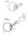
- ein gemäß dem Stand der Technik ausgebildetes Abdichtele- ment im Einsatz am Auge und
- FIG 14
- die Anordnung gemäß dem Stand der Technik gemäß
FIG 13 in einer Schnittdarstellung. - FIG 15
- ein Abdichtelement gemäß dem Stand der Technik gemäß
FIG 13 in einer vergrößerten Schnittdarstellung,und 14 - FIG 16
- das Abdichtelement gemäß dem Stand der Technik gemäß
FIG 15 in einer perspektivischen Darstellung, - FIG 17
- ein weiteres Abdichtelement gemäß der Erfindung in einer Schnittdarstellung,
- FIG 18
- ein weiteres Abdichtelement in einer Schnittdarstellung und
- FIG 19
- das Abdichtelement gemäß
FIG 18 in einer perspektivischen Darstellung.
- FIG. 1
- a sealing element with a recorded surgical instrument during an operative procedure on an eye in a perspective view,
- FIG. 2
- the arrangement according to
FIG. 1 in a cut representation, - FIG. 3
- the arrangement according to
FIG. 2 in an enlarged section, - FIG. 4
- the sealing element according to
1 to 3 alone in a sectional view, - FIG. 5
- the sealing element according to
FIG. 4 in a perspective view, - FIG. 6
- Another embodiment of a sealing member with respect to
FIG. 4 modified contact area in a sectional view, - FIG. 7
- the sealing element according to
FIG. 6 in a perspective view, - FIG. 8
- a further embodiment of a sealing element in a sectional view,
- FIG. 9
- a further embodiment of a sealing element with a laser surgical instrument when used on the eye in a perspective view,
- FIG. 10
- the arrangement according to
FIG. 9 in a sectional view, - FIG. 11
- this in
FIGS. 9 and 10 used sealing element alone in a sectional view, - FIG. 12
- the sealing element according to
FIG. 11 in a perspective view, - FIG. 13
- a trained according to the prior art Abdichtele- ment in use on the eye and
- FIG. 14
- the arrangement according to the prior art according to
FIG. 13 in a sectional view. - FIG. 15
- a sealing element according to the prior art according to
FIGS. 13 and 14 in an enlarged sectional view, - FIG. 16
- the sealing element according to the prior art according to
FIG. 15 in a perspective view, - FIG. 17
- another sealing element according to the invention in a sectional view,
- FIG. 18
- another sealing element in a sectional view and
- FIG. 19
- the sealing element according to
FIG. 18 in a perspective view.
Einander entsprechende Teile und Größen sind in den
Das Auge ist mit 10 bezeichnet. In dem von der Sclera 11, Hornhaut (Cornea) 12 und Lederhaut 19 umschlossenen Augeninnenraum sind der Glaskörper 16 und vor dem Glaskörper 16 die Augenlinse 15 angeordnet. Die Augenlinse 15 ist von dem nicht bezeichneten Kapselsack umschlossen und über die Zonularfasern an dem Ciliarmuskel an der Sclera 11 aufgehängt. Vor der Augenlinse 15 ist die Iris (oder: Regenbogenhaut) 14, die die Pupille 13 umschließt und deren Größe einstellt, angeordnet. Vor der Iris 14 und der Pupille 13 befindet sich die vordere Augenkammer 17, die mit Augenflüssigkeit gefüllt ist und von der transparenten Hornhaut 12 nach vorne begrenzt wird.The eye is designated 10. In the inner space of the eye enclosed by the
Eine Katarakt-Operation umfasst nun in der Regel die folgenden Verfahrensschritte:A cataract surgery now typically involves the following procedural steps:
Zunächst wird mittels eines chirurgischen Instruments, beispielsweise einer Kanüle, der vorderer Kapselsack der Augenlinse 15 eröffnet, wobei eine in der Regel 4,5 mm bis 5,5 mm große Öffnung erzeugt wird (Capsulorrhexis). Durch Einbringen einer Irrigationsflüssigkeit, z.B. BSS, wird die Augenlinse 15 vom Kapselsack gelöst und dadurch mobilisiert (Hydrodisektion).First, the front capsular bag of the
Sodann werden bei einer Operationstechnik mit nur einem Instrument (monomanuelle Technik) nur eine Öffnung (Inzision, Schnitt) 18 in der Hornhaut (cornea), insbesondere am Limbus, vorzugsweise am Übergang von Hornhaut 12 zu Sclera 11, und bei einer anderen Operationstechnik mit zwei Instrumenten (bimanuelle Technik) werden, in der Regel an entgegengesetzten Seiten der Hornhaut (cornea), insbesondere am Limbus, zwei Inzisionen erzeugt. Im Fall von nur einer Inzision wird ein Operationsinstrument eingesetzt, das eine integrierte Irrigation (oder: Zuführung von Irrigationsflüssigkeit) und Aspiration (oder: Absaugen von Gewebe und Flüssigkeit) aufweist. Im Fall von zwei Inzisionen wird durch eine Inzision ein Operationsinstrument mit integrierter Aspiration eingeführt und durch die weitere Inzision ein separates Irrigationsinstrument zur Irrigation.Then, in an operation technique with only one instrument (monomanual technique), only one opening (incision, cut) 18 in the cornea , in particular at the limbus, preferably at the junction of
Es wird nun Irrigationsflüssigkeit, im Allgemeinen ebenfalls BSS, in den Kapselsack eingespült und durch den dadurch aufgebauten Druck insbesondere verhindert, dass die hintere Wandung des Kapselsackes zu nahe an das Operationsinstrument 3 gelangt, und zugleich kann zusätzlich der Kapselsack gereinigt werden.It is now Irrigationsflüssigkeit, generally also BSS, flushed into the capsular bag and prevented by the pressure built up thereby in particular that the rear wall of the capsular bag gets too close to the
In
Durch die Öffnung 18 ist ein an sich bekanntes mit Ultraschallschwingungen arbeitendes Operationsinstrument 3 hindurch geführt, das in den Linsenkapselsack mit seinem freien Ende 3A eindringt und die im Kapselsack befindliche Augenlinse 15 aus dem Kapselsack extrahiert. Das Operationsinstrument 3 ist nadel- oder kanülenförmig ausgebildet und weist eine nicht näher dargestellte Aspirationsöffnung an seinem freien Ende 3A sowie einen von der Aspirationsöffnung durch das Innere des Operationsinstruments 3 verlaufenden Aspirations- oder Ansaugkanal auf.Through the
Durch ein an einem verbreiterten Anschlussbereich am anderen Ende 3B des Operationsinstruments 3 lösbar angeschlossenes oder angekoppeltes Handstück 5, insbesondere mittels eines im Handstück 5 befindlichen piezoelektrischen Schwingungsantrieb (Piezoantrieb), wird das Operationsinstrument 3 in Schwingungen im Ultraschallspektrum, typischerweise oberhalb 20 kHz, beispielsweise um die 40 kHz, versetzt und zerstört durch die dadurch eingebrachte Energie das Gewebe der Augenlinse 15.By means of a
Das Handstück 5 weist seinerseits einen internen Aspirationskanal auf, der den Aspirationskanal im Operationsinstrument 3 mit einem Aspirationsanschluss (oder: Aspirationsschlauch) 50 am Handstück 5 verbindet. Der Aspirationsanschluss 50 wiederum ist mit einer Saug- oder Fördereinrichtung, insbesondere einer Pumpe, zum Erzeugen eines Unterdrucks typischerweise im Grobvakuumbereich und/oder im Bereich eines Absolutdrucks von 700 mbar bis 800 mbar, verbunden. Dadurch wird das zerstörte oder zersetzte Gewebe der Augenlinse 15 in der Regel zusammen mit im Kapselsack befindlicher Flüssigkeit in der in
Außerdem weist das Handstück 5 einen weiteren Anschluss 51 auf, der an ein Kabel angeschlossen ist zum Zuführen elektrischer Energie für den Piezoantrieb.In addition, the
Das dargestellte Handstück 5 weist also eine integrierte Aspiration auf.The illustrated
Die Irrigation wird in einer Ausführungsform mittels eines gesonderten Handstücks bewerkstelligt. In einer anderen Ausführungsform weist das Handstück 5 zusätzlich einen weiteren, nicht dargestellten Irrigationsanschluss und einen internen Irrigationskanal zum Zuführen von Irrigationsflüssigkeit (oder: Spül- und/oder Kühlflüssigkeit), beispielsweise BSS, auf. Aus einem Irrigationsausgang, in den der Irrigationskanal mündet, strömt die Irrigationsflüssigkeit dann aus dem Handstück 5 aus und durch den Zwischenraum zwischen der Außenwand des durch den Durchgang 25 geführten Operationsinstrument 3 und der den Durchgang 25 umschließenden Wandung des Abdichtelements 2 und anschließend durch die Öffnung 18 im das Operationsinstrument 3 umgebenden äußeren Bereich in die vordere Augenkammer 17 und den Kapselsack nach.The irrigation is accomplished in one embodiment by means of a separate handpiece. In another embodiment, the
Dieses Nachführen von Irrigationsflüssigkeit dient dazu, den durch die Aspiration verursachten Druck- und Materialverlust im Augeninneren auszugleichen.This tracking of irrigation fluid serves to balance the loss of pressure and material inside the eye caused by the aspiration.
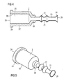
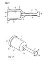
Das Operationsinstrument 3 ist nun in einem Abdichtelement 2 angeordnet und von diesem umhüllt. Das Abdichtelement 2 umfasst einen Aufnahmebereich 22 mit einem, beispielsweise zylindrischen, Aufnahmeraum 26, der sich am Ende 2A öffnet und dort von einem Anschlussflansch 24 umgeben ist, der weiter nach außen ragt als die übrige Wandung des Aufnahmebereichs 22. Der Aufnahmebereich 22 ist über einen Übergangsbereich 23 mit einem Rüsselbereich 21 verbunden, wobei der Durchmesser vom Aufnahmebereich 22 zum Rüsselbereich 21 über den Übergangsbereich 23, beispielsweise gestuft, abnimmt. Zum Übergangsbereich 23 hin ist eine konische Verjüngung zur besseren Flussdynamik gebildet. Innerhalb des Rüsselbereichs 21 und des Übergangsbereichs 23 ist ein, beispielsweise zylindrischer, Durchgang 25 von im Wesentlichen konstantem Durchmesser, der kleiner ist als der Durchmesser des Aufnahmebereichs 26, ausgebildet. Dieser Durchgang 25 mündet in einem Abdichtbereich 20 am vorderen freien Ende 2B nach außen.The
In dem Aufnahmebereich 26 des Abdichtelements 2 ist das Ende des Handstücks 5 und der Anschlussbereich 30 des Operationsinstruments 3 aufgenommen. Ein Gewinde 29 im Aufnahmebereich 26 wird dazu auf ein Außengewinde des Handstücks 5 aufgedreht, so dass eine Schraubverbindung realisiert ist.In the receiving
Durch den Durchgang 25 des Abdichtelements 2 verläuft das (übrige, nadelförmige) Operationsinstrument 3 und ragt mit seinem freien Ende 3A und einem anschließenden Bereich aus dem Abdichtelement 2 heraus und ist somit mit seinem Ende 3A für die Operation verfügbar.Through the
Das Abdichtelement 2 besteht zumindest im Bereich des Rüssels 21 aus einem elastischen Material, beispielsweise aus einem oder auf Basis von einem natürlichen oder synthetischen Kautschuk oder Elastomer und/oder einem thermoplastischen Elastomer. Ein besonders geeignetes Material ist Silicon oder Silicongummi (Siloxankautschuk) oder ein Material mit Silicon, insbesondere ein schwingungsdämpfendes Material wie ein Gemisch mit Elastomer, insbesondere Siloxan-Elastomer, Collagen und Wasser, welches aus
Um dem Operateur die Möglichkeit zu geben zu erkennen, wo das im Allgemeinen farblose und transparente Silicongummi des Abdichtelements 2 auf der transparenten Hornhaut 12 anliegt, kann in einer besonderen Ausführungsform das Abdichtelement 2 im Bereich des Abdichtbereichs 20 eingefärbt sein.In order to enable the surgeon to recognize where the generally colorless and transparent silicone rubber of the sealing
Die Wandstärke im Aufnahmebereich 22 und im Übergangsbereich 23 ist vorzugsweise deutlich größer als im Rüsselbereich 21, so dass der Rüsselbereich 21 deutlich verformbarer oder flexibler ist als der Aufnahmebereich 22. Typische Wandstärken für Aufnahmebereich 22 und Übergangsbereich 23 sind größer als 0,7 mm, während die Wanddicke des Rüsselbereichs 21 typischerweise zwischen 0,2 mm und 0,4 mm gewählt wird.The wall thickness in the receiving
Durch die in
Am Ende des Rüssels 21 des Abdichtelements 2 an dessen Ende 2B ist ein Abdichtbereich 20 ausgebildet, der gemäß
Wenn nun der Operateur das Handstück 5 mit dem Operationsinstrument 3 durch die Öffnung 18 nach innen zum oder im Kapselsack oder zur Augenlinse 15 zu bewegt, so drückt er zugleich den Rüssel 21 mit seinem Abdichtbereich 20 gegen die äußere Oberfläche der Hornhaut 12 und/oder Sclera 11. Die anliegende ringförmige Abdichtfläche am Abdichtbereich 20 ist von der Öffnung 18 beabstandet und umgibt die Öffnung 18 vollständig, Dadurch dichtete der Abdichtbereich 20 die Öffnung 18 ringsum gegen die äußere Oberfläche der Hornhaut 12 und/oder Sclera 11 ab.If now the surgeon moves the
Durch die elastischen Verformbarkeit oder reversible Stauchbarkeit des Rüssels 21 bei axialer Druckbelastung kann der Rüssel 21 vom Operateur unter einem ausreichenden Anpressdruck gegen die Augenaußenhaut gedrückt werden, um die erforderliche druckdichte Abdichtung der Öffnung 18 zu erreichen. Aufgrund der vergleichsweise großen Verformwege des Rüssels 21 und der dadurch bewirkten relativ großen elastischen Rückstellkräfte im Rüssel 21 einerseits und deren räumlicher Entfernung von der Öffnung 18 andererseits ist die Abdichtung relativ unempfindlich gegenüber einer Positionsänderung des Operationsinstrument 3 mit dem Rüssel 21 sowohl in lateraler als auch axialer Richtung. Die Abdichtfläche des Abdichtbereichs 20 bleibt auch bei Änderungen der Form der Öffnung 18 durch die Bewegungen des Operationsinstrument 3 dennoch vollständig auf der Augenaußenhaut (hier 11 oder 12) aufliegen.Due to the elastic deformability or reversible compressibility of the
Die Wandung des Rüssels 21 im Abdichtbereich 20 wirkt ferner in einer Ausführungsform mit integrierter Irrigation durch die elastischen Rückstellkräfte nach innen in ausreichendem Maße dem durch die Irrigationsflüssigkeit aufgebauten Innendruck im Rüssel 21 entgegen. Ein Flüssigkeitsleck für die durch die Öffnung 18 strömende Irrigationsflüssigkeit um die Öffnung 18 wird somit zuverlässig vermieden.The wall of the
Die
Das Operationsinstrument 3 in
Die
Im Unterschied zum Stand der Technik gemäß
In der weiteren Ausführungsform eines Abdichtelements 2 gemäß
Zur Beendigung der Kataraktoperation wird nach vollständiger Entfernung der natürlichen Augenlinse und Reinigung des Kapselsackes nun eine künstliche Augenlinse in den Kapselsack eingesetzt und anschließend werden die Wunden verschlossen.To complete the cataract operation, after complete removal of the natural eye lens and cleaning of the capsular bag, an artificial eye lens is now inserted into the capsular bag and subsequently the wounds are closed.
- 2, 2'2, 2 '
- Abdichtelementsealing
- 2A, 2B2A, 2B
- EndeThe End
- 33
- Operationsinstrumentsurgical instrument
- 3A, 3B3A, 3B
- EndeThe End
- 55
- Handstückhandpiece
- 1010
- Augeeye
- 1111
- Sclerasclera
- 1212
- Hornhautcornea
- 1313
- Pupillepupil
- 1414
- Irisiris
- 1515
- Augenlinseeye lens
- 1616
- Glaskörpervitreous
- 1717
- vordere Augenkammeranterior chamber of the eye
- 1818
- Öffnungopening
- 1919
- Lederhautdermis
- 20, 20'20, 20 '
- Abdichtbereichsealing
- 21, 21'21, 21 '
- Rüsseltrunk
- 22, 22'22, 22 '
- Aufnahmebereichreception area
- 23, 23'23, 23 '
- ÜbergangsbereichTransition area
- 24, 24'24, 24 '
- Anschlussflanschflange
- 25, 25'25, 25 '
- Durchgangpassage
- 2727
- Faltewrinkle
- 28, 28'28, 28 '
- Abdichtbereichsealing
- 29, 29'29, 29 '
- Gewindethread
- 3030
- Anschlussbereichterminal area
- 5050
- IrrigationsanschlussIrrigationsanschluss
- 5151
- Anschlussconnection
- α, β, γα, β, γ
- Winkelangle
Claims (31)
- Device for sealing an opening (18) in a human or animal eye (10) comprising
at least one sealing element (2)a) having a passageway (25, 26) surrounded by a wall,b) and at least one sealing region (20) which is or can be placed on an outer surface of the eye tissue surrounding the opening with a sealing surface entirely surrounding the opening,c) wherein a surgical instrument (3) is or can be introduced through the passageway in the sealing element and through the opening into the eye interior (15, 17), characterised in thatd) the passageway in the sealing element comprises a first passageway region (26) and a second passageway region (25) adjoining the first passageway region, wherein the first passageway region at least partially forms a receptacle chamber for receiving a handle (5) for the surgical instrument and the surgical instrument is or can be guided through the second passageway region and the sealing region ande) wherein the first passageway region (26) has at least predominantly a larger internal cross-section than the second passageway region (25). - Device according to claim 1, wherein the opening is surgically created and/or is created in the integument of the eye, particularly in the cornea (12) and/or the sclera (11) and/or the Tunica fibrosa (19).
- Device according to one or more of the preceding claims wherein
the sealing element is elastically deformable at least in the sealing region. - Device according to one or more of the preceding claims wherein the sealing surface of the sealing region is configured essentially annular in the unformed condition.
- Device according to one or more of the preceding claims, wherein the sealing surface of the sealing region is configured planar in the unformed condition.
- Device according to one or more of the claims 1 to 4, wherein the sealing surface of the sealing region is formed curved in the unformed condition to adapt to the curvature of the eye tissue, particularly the cornea, sclera and/or Tunica fibrosa.
- Device according to one or more of the preceding claims, wherein the sealing region broadens toward the sealing surface.
- Device according to claim 7, wherein the sealing region broadens concavely and/or in a funnel-shaped or trumpet-shaped manner toward the sealing surface.
- Device according to claim 7, wherein the sealing region broadens convexly and/or in a bell-shaped or bowl-shaped manner toward the sealing surface.
- Device according to one or more of the preceding claims, wherein a dimension of the sealing surface in the direction toward the opening and/or in the radial direction and/or the thickness of the wall in the sealing region is selected to lie in a range between 0.1 mm and 7 mm, particularly between 0.2 mm and 1.5 mm.
- Device according to one or more of the preceding claims, wherein a maximum diameter of the area of the eye tissue enclosed by the sealing surface is selected to lie in a range between 3 mm and 10 mm.
- Device according to one or more of the preceding claims, wherein a maximum diameter of the opening in the eye tissue lies in a range between approximately 1.5 mm and approximately 6 mm.
- Device according to one or more of the preceding claims, wherein the sealing surface of the sealing region of the sealing element placed on the eye tissue is spaced apart from the opening, particularly by a minimum distance in a range between 0.1 mm and 2 mm and/or wherein the minimum diameter of the area of the eye tissue enclosed by the sealing surface is greater than the maximum diameter of the opening, particularly by an amount in the range between 0.1 mm and 2 mm.
- Device according to one of the preceding claims, wherein the wall of the first passageway region is at least predominantly thicker than the wall of the second passageway region.
- Device according to one of the preceding claims, wherein the sealing element has a proboscis region within which the second passageway region extends.
- Device according to one of the preceding claims, wherein the wall of the second passageway region has at least one peripheral fold or is configured like a bellows.
- Device according to one or more of the preceding claims, wherein the passageway or the second passageway region opens outwardly in the sealing region.
- Device according to one or more of the preceding claims, wherein the passageway or the second passageway region opens outwardly in an aperture region and the sealing region is configured on the wall of the passageway, particularly as a peripheral sealing lip.
- Device according to claim 18, wherein, provided in the aperture region of the passageway, is a second sealing region which seals or lies with a second sealing surface against the eye tissue on the inner peripheral surface of the opening.
- Device according to one or more of the preceding claims, wherein the sealing element is configured in one piece, particularly as a moulded body made from one material.
- Device according to one or more of the preceding claims, wherein the sealing element is at least partially elastic or is made from an elastic material, particularly from a natural rubber or a material based on natural rubber or synthetic rubber or an elastomer, preferably siloxane rubber.
- Device according to one or more of the preceding claims, wherein the sealing region is coloured or configured optically slightly transparent or not transparent, at least in the region of the sealing surface.
- Device according to one or more of the preceding claims, comprising irrigation means for conducting irrigation fluid through the passageway of the sealing element, particularly through the intermediate space between the surgical instrument and the sealing element, and through the opening into the eye interior.
- Device according to claim 23, wherein the irrigation means is integrated into a handle to which the surgical instrument can be or is connected.
- Device according to one or more of the preceding claims, wherein the surgical instrument is configured elongate, particularly needle or cannula-shaped and/or has an outer diameter of not more than 3 mm.
- Device according to one or more of the preceding claims, wherein the surgical instrument is an ultrasonic surgical instrument.
- Device according to one of the claims 1 to 27, wherein the surgical instrument is a photolytic surgical instrument.
- Device according to one of the preceding claims, wherein the surgical instrument is a surgical instrument for phacolysis, particularly phacoemulsification.
- Device according to one of the claims 1 to 25, wherein the surgical instrument is a cutting or scalpel surgical instrument.
- Device according to claim 29, wherein the surgical instrument is a surgical instrument for vitrectomy.
- Device according to one of the claims 1 to 25, wherein the surgical instrument is an irrigation and/or manipulation instrument.
Applications Claiming Priority (2)
| Application Number | Priority Date | Filing Date | Title |
|---|---|---|---|
| DE102005008235A DE102005008235A1 (en) | 2005-02-22 | 2005-02-22 | Sealing device for use with an eye operating instrument has a sealing element that is set down on an area around an opening made in the eye to permit the passage of an instrument or laser beam, while protecting the eye tissue |
| PCT/EP2006/000653 WO2006089611A1 (en) | 2005-02-22 | 2006-01-26 | Apparatus for sealing an opening in a human or animal eye |
Publications (2)
| Publication Number | Publication Date |
|---|---|
| EP1858459A1 EP1858459A1 (en) | 2007-11-28 |
| EP1858459B1 true EP1858459B1 (en) | 2011-03-02 |
Family
ID=36218664
Family Applications (1)
| Application Number | Title | Priority Date | Filing Date |
|---|---|---|---|
| EP06722984A Active EP1858459B1 (en) | 2005-02-22 | 2006-01-26 | Apparatus for sealing an opening in a human or animal eye |
Country Status (7)
| Country | Link |
|---|---|
| US (2) | US20080281277A1 (en) |
| EP (1) | EP1858459B1 (en) |
| JP (1) | JP2008531077A (en) |
| AT (1) | ATE499915T1 (en) |
| DE (2) | DE102005008235A1 (en) |
| ES (1) | ES2362174T3 (en) |
| WO (1) | WO2006089611A1 (en) |
Families Citing this family (43)
| Publication number | Priority date | Publication date | Assignee | Title |
|---|---|---|---|---|
| US8852137B2 (en) | 2010-11-15 | 2014-10-07 | Aquesys, Inc. | Methods for implanting a soft gel shunt in the suprachoroidal space |
| US8758290B2 (en) | 2010-11-15 | 2014-06-24 | Aquesys, Inc. | Devices and methods for implanting a shunt in the suprachoroidal space |
| US20120123316A1 (en) | 2010-11-15 | 2012-05-17 | Aquesys, Inc. | Intraocular shunts for placement in the intra-tenon's space |
| AU2007269259B2 (en) * | 2006-06-30 | 2012-05-31 | Aquesys Inc. | Methods, systems and apparatus for relieving pressure in an organ |
| US8663303B2 (en) | 2010-11-15 | 2014-03-04 | Aquesys, Inc. | Methods for deploying an intraocular shunt from a deployment device and into an eye |
| US8828070B2 (en) | 2010-11-15 | 2014-09-09 | Aquesys, Inc. | Devices for deploying intraocular shunts |
| US20120123317A1 (en) * | 2010-11-15 | 2012-05-17 | Aquesys, Inc. | Methods for implanation of glaucoma shunts |
| US8308701B2 (en) | 2010-11-15 | 2012-11-13 | Aquesys, Inc. | Methods for deploying intraocular shunts |
| US8974511B2 (en) | 2010-11-15 | 2015-03-10 | Aquesys, Inc. | Methods for treating closed angle glaucoma |
| US8721702B2 (en) | 2010-11-15 | 2014-05-13 | Aquesys, Inc. | Intraocular shunt deployment devices |
| US10085884B2 (en) | 2006-06-30 | 2018-10-02 | Aquesys, Inc. | Intraocular devices |
| US8801766B2 (en) | 2010-11-15 | 2014-08-12 | Aquesys, Inc. | Devices for deploying intraocular shunts |
| US8852256B2 (en) | 2010-11-15 | 2014-10-07 | Aquesys, Inc. | Methods for intraocular shunt placement |
| US9095411B2 (en) | 2010-11-15 | 2015-08-04 | Aquesys, Inc. | Devices for deploying intraocular shunts |
| US8992459B2 (en) * | 2009-02-13 | 2015-03-31 | Art, Limited | Apparatus and method for phacoemulsification |
| DE102009015911A1 (en) | 2009-04-03 | 2010-10-07 | Carl Zeiss Meditec Ag | Device and method for removing a lenticle from the cornea |
| US8343106B2 (en) | 2009-12-23 | 2013-01-01 | Alcon Research, Ltd. | Ophthalmic valved trocar vent |
| AU2010341732B2 (en) | 2009-12-23 | 2014-03-06 | Alcon Inc. | Ophthalmic valved trocar cannula |
| US9408746B2 (en) * | 2010-03-31 | 2016-08-09 | Ocuject, Llc | Device and method for intraocular drug delivery |
| DE102010047010B4 (en) * | 2010-09-30 | 2017-03-09 | Carl Zeiss Meditec Ag | Control device for an ophthalmic surgical system |
| US10842671B2 (en) | 2010-11-15 | 2020-11-24 | Aquesys, Inc. | Intraocular shunt placement in the suprachoroidal space |
| US8585629B2 (en) | 2010-11-15 | 2013-11-19 | Aquesys, Inc. | Systems for deploying intraocular shunts |
| US8852136B2 (en) | 2011-12-08 | 2014-10-07 | Aquesys, Inc. | Methods for placing a shunt into the intra-scleral space |
| US9610195B2 (en) | 2013-02-27 | 2017-04-04 | Aquesys, Inc. | Intraocular shunt implantation methods and devices |
| US9808373B2 (en) | 2013-06-28 | 2017-11-07 | Aquesys, Inc. | Intraocular shunt implantation |
| US10080682B2 (en) | 2011-12-08 | 2018-09-25 | Aquesys, Inc. | Intrascleral shunt placement |
| US8765210B2 (en) | 2011-12-08 | 2014-07-01 | Aquesys, Inc. | Systems and methods for making gelatin shunts |
| NL2008458C2 (en) * | 2012-03-09 | 2013-09-10 | D O R C Dutch Ophthalmic Res Ct International B V | EYE-SURGICAL INSTRUMENT AND EYE-SURGICAL SET. |
| US9504603B2 (en) | 2012-04-02 | 2016-11-29 | Ocuject, Llc | Intraocular delivery devices and methods therefor |
| US9421129B2 (en) | 2012-04-02 | 2016-08-23 | Ocuject, Llc | Intraocular delivery devices and methods therefor |
| US9125723B2 (en) | 2013-02-19 | 2015-09-08 | Aquesys, Inc. | Adjustable glaucoma implant |
| US10159600B2 (en) | 2013-02-19 | 2018-12-25 | Aquesys, Inc. | Adjustable intraocular flow regulation |
| EP2781207A1 (en) * | 2013-03-21 | 2014-09-24 | Christian Simader | Apparatus for application on an eye |
| US20150038894A1 (en) * | 2013-08-02 | 2015-02-05 | Alex Urich | Occlusion-activated heat supression infusion sleeve |
| JP6324013B2 (en) * | 2013-09-30 | 2018-05-16 | マニー株式会社 | Cannula |
| AU2014348536B2 (en) | 2013-11-14 | 2017-01-12 | Aquesys, Inc. | Intraocular shunt inserter |
| KR102081855B1 (en) | 2015-06-03 | 2020-02-26 | 아큐시스, 인코포레이티드 | External placement of intraocular shunts |
| CN109561987A (en) | 2016-06-02 | 2019-04-02 | 阿奎西斯公司 | Intraocular drug delivery |
| JP6902966B2 (en) * | 2017-08-30 | 2021-07-14 | マニー株式会社 | Back flush needle |
| US11246753B2 (en) | 2017-11-08 | 2022-02-15 | Aquesys, Inc. | Manually adjustable intraocular flow regulation |
| US10952898B2 (en) | 2018-03-09 | 2021-03-23 | Aquesys, Inc. | Intraocular shunt inserter |
| US11135089B2 (en) | 2018-03-09 | 2021-10-05 | Aquesys, Inc. | Intraocular shunt inserter |
| BR112023025179A2 (en) * | 2021-07-20 | 2024-02-27 | Alcon Inc | CANNULAS FOR OPHTHALMIC PROCEDURES |
Family Cites Families (19)
| Publication number | Priority date | Publication date | Assignee | Title |
|---|---|---|---|---|
| US2480737A (en) * | 1948-03-08 | 1949-08-30 | Jayle Gaetan Jean-Edward | Cutting instrument particularly useful in connection with corneal grafting |
| US3659607A (en) * | 1968-09-16 | 1972-05-02 | Surgical Design Corp | Method for performing surgical procedures on the eye |
| US3528410A (en) * | 1968-09-16 | 1970-09-15 | Surgical Design Corp | Ultrasonic method for retinal attachment |
| US3732858A (en) * | 1968-09-16 | 1973-05-15 | Surgical Design Corp | Apparatus for removing blood clots, cataracts and other objects from the eye |
| US3528425A (en) * | 1968-09-16 | 1970-09-15 | Surgical Design Corp | Apparatus for performing surgical procedures on the eye |
| US4526171A (en) * | 1980-01-15 | 1985-07-02 | Schachar Ronald A | Cornea incision device |
| US4688570A (en) * | 1981-03-09 | 1987-08-25 | The Regents Of The University Of California | Ophthalmologic surgical instrument |
| US4381007A (en) * | 1981-04-30 | 1983-04-26 | The United States Of America As Represented By The United States Department Of Energy | Multipolar corneal-shaping electrode with flexible removable skirt |
| US4808154A (en) * | 1983-10-26 | 1989-02-28 | Freeman Jerre M | Phacoemulsification/irrigation and aspiration sleeve apparatus |
| EP0216952A1 (en) * | 1985-10-04 | 1987-04-08 | Erbe Elektromedizin GmbH. | Device for subretinal drainage |
| US5324281A (en) * | 1987-03-09 | 1994-06-28 | Summit Technology, Inc. | Laser reprofiling system employing a photodecomposable mask |
| EP0497908B1 (en) * | 1989-10-25 | 1997-03-19 | DODICK, Jack Murray | Surgical instrument with input power transducer |
| US5071421A (en) * | 1990-02-08 | 1991-12-10 | Stahl Norman O | Method for preventing damage to tissue during ultrasonic surgery |
| AU6268396A (en) * | 1995-06-02 | 1996-12-18 | Surgical Design Corporation | Phacoemulsification handpiece, sleeve, and tip |
| US5645530A (en) * | 1995-08-28 | 1997-07-08 | Alcon Laboratories, Inc. | Phacoemulsification sleeve |
| IL119813A (en) * | 1996-06-13 | 2000-07-26 | One Way Ocular Technology Ltd | Surgical sealing sleeve |
| US5906611A (en) * | 1997-07-28 | 1999-05-25 | Dodick; Jack Murray | Surgical instrument with laser target |
| US7077848B1 (en) * | 2000-03-11 | 2006-07-18 | John Hopkins University | Sutureless occular surgical methods and instruments for use in such methods |
| AUPR770901A0 (en) * | 2001-09-11 | 2001-10-11 | James Neilson, Geoffrey | Capsule sealing method |
-
2005
- 2005-02-22 DE DE102005008235A patent/DE102005008235A1/en not_active Withdrawn
-
2006
- 2006-01-26 DE DE502006008994T patent/DE502006008994D1/en active Active
- 2006-01-26 US US11/884,895 patent/US20080281277A1/en not_active Abandoned
- 2006-01-26 EP EP06722984A patent/EP1858459B1/en active Active
- 2006-01-26 ES ES06722984T patent/ES2362174T3/en active Active
- 2006-01-26 JP JP2007555479A patent/JP2008531077A/en active Pending
- 2006-01-26 AT AT06722984T patent/ATE499915T1/en active
- 2006-01-26 WO PCT/EP2006/000653 patent/WO2006089611A1/en active Application Filing
-
2010
- 2010-10-07 US US12/900,212 patent/US20110230890A1/en not_active Abandoned
Also Published As
| Publication number | Publication date |
|---|---|
| DE502006008994D1 (en) | 2011-04-14 |
| ES2362174T3 (en) | 2011-06-29 |
| US20080281277A1 (en) | 2008-11-13 |
| ATE499915T1 (en) | 2011-03-15 |
| US20110230890A1 (en) | 2011-09-22 |
| JP2008531077A (en) | 2008-08-14 |
| EP1858459A1 (en) | 2007-11-28 |
| WO2006089611A1 (en) | 2006-08-31 |
| DE102005008235A1 (en) | 2006-08-31 |
Similar Documents
| Publication | Publication Date | Title |
|---|---|---|
| EP1858459B1 (en) | Apparatus for sealing an opening in a human or animal eye | |
| DE69930106T2 (en) | ANGLED PHAKOEMULGATOR NEEDLE WITH CONVERGING OUTER SURFACE AND SMALLING INNER CHANNEL | |
| DE69630188T2 (en) | PHACOEMULSIFICATION HANDPIECE, CUFF AND LACE | |
| DE102004021754A1 (en) | Device for removing epithelial cells from a lens capsular bag of a human or animal eye | |
| DE602005002785T2 (en) | Surgical device | |
| EP0623328B1 (en) | Surgical apparatus for pulverizing and removing the nucleus from the lens of an eye of a living creature | |
| US5873883A (en) | Hydraulic capsulorhexitome | |
| DE60017095T2 (en) | FLAP FOR A TINY CAPSULORHEXIS | |
| DE602006000163T2 (en) | Tip for phacoemulsification | |
| US7967775B2 (en) | Irrigation/aspiration tip | |
| EP1916977B1 (en) | Contact glass for ophthalmic surgery | |
| US20090132040A1 (en) | Ocular Implant Delivery System and Method | |
| US6629980B1 (en) | Instrument and method for creating an intraocular incision | |
| EP1632205A1 (en) | Surgical apparatus | |
| US20040116950A1 (en) | Instrument and method for creating an intraocular incision | |
| US7704244B2 (en) | Surgical method | |
| EP1759675B1 (en) | Nozzle for a surgical irrigating handpiece | |
| EP1767173A1 (en) | Surgical apparatus | |
| US20210100686A1 (en) | Intraocular devices and methods | |
| DE60301121T2 (en) | Surgical tool holder | |
| KR101886999B1 (en) | A phakic intraocular lens position adjustor | |
| US20060036215A1 (en) | Surgical apparatus | |
| EP0997105B1 (en) | Apparatus for removal of focus of disease in human and veterinary medicine | |
| US20210315737A1 (en) | Anterior chamber maintainer (acm) | |
| RU2806615C2 (en) | Sliding injector with hydraulic damping for delivery of lens component inside eye |
Legal Events
| Date | Code | Title | Description |
|---|---|---|---|
| PUAI | Public reference made under article 153(3) epc to a published international application that has entered the european phase |
Free format text: ORIGINAL CODE: 0009012 |
|
| 17P | Request for examination filed |
Effective date: 20070509 |
|
| AK | Designated contracting states |
Kind code of ref document: A1 Designated state(s): AT BE BG CH CY CZ DE DK EE ES FI FR GB GR HU IE IS IT LI LT LU LV MC NL PL PT RO SE SI SK TR |
|
| DAX | Request for extension of the european patent (deleted) | ||
| 17Q | First examination report despatched |
Effective date: 20080923 |
|
| GRAP | Despatch of communication of intention to grant a patent |
Free format text: ORIGINAL CODE: EPIDOSNIGR1 |
|
| GRAS | Grant fee paid |
Free format text: ORIGINAL CODE: EPIDOSNIGR3 |
|
| GRAA | (expected) grant |
Free format text: ORIGINAL CODE: 0009210 |
|
| AK | Designated contracting states |
Kind code of ref document: B1 Designated state(s): AT BE BG CH CY CZ DE DK EE ES FI FR GB GR HU IE IS IT LI LT LU LV MC NL PL PT RO SE SI SK TR |
|
| REG | Reference to a national code |
Ref country code: GB Ref legal event code: FG4D Free format text: NOT ENGLISH |
|
| REG | Reference to a national code |
Ref country code: CH Ref legal event code: EP |
|
| REG | Reference to a national code |
Ref country code: IE Ref legal event code: FG4D Free format text: LANGUAGE OF EP DOCUMENT: GERMAN |
|
| REF | Corresponds to: |
Ref document number: 502006008994 Country of ref document: DE Date of ref document: 20110414 Kind code of ref document: P |
|
| REG | Reference to a national code |
Ref country code: DE Ref legal event code: R096 Ref document number: 502006008994 Country of ref document: DE Effective date: 20110414 |
|
| RAP2 | Party data changed (patent owner data changed or rights of a patent transferred) |
Owner name: THYZEL, REINHARDT |
|
| RIN2 | Information on inventor provided after grant (corrected) |
Inventor name: THYZEL, REINHARDT |
|
| REG | Reference to a national code |
Ref country code: ES Ref legal event code: FG2A Ref document number: 2362174 Country of ref document: ES Kind code of ref document: T3 Effective date: 20110629 |
|
| REG | Reference to a national code |
Ref country code: NL Ref legal event code: VDEP Effective date: 20110302 |
|
| PG25 | Lapsed in a contracting state [announced via postgrant information from national office to epo] |
Ref country code: LT Free format text: LAPSE BECAUSE OF FAILURE TO SUBMIT A TRANSLATION OF THE DESCRIPTION OR TO PAY THE FEE WITHIN THE PRESCRIBED TIME-LIMIT Effective date: 20110302 Ref country code: GR Free format text: LAPSE BECAUSE OF FAILURE TO SUBMIT A TRANSLATION OF THE DESCRIPTION OR TO PAY THE FEE WITHIN THE PRESCRIBED TIME-LIMIT Effective date: 20110603 Ref country code: SE Free format text: LAPSE BECAUSE OF FAILURE TO SUBMIT A TRANSLATION OF THE DESCRIPTION OR TO PAY THE FEE WITHIN THE PRESCRIBED TIME-LIMIT Effective date: 20110302 Ref country code: LV Free format text: LAPSE BECAUSE OF FAILURE TO SUBMIT A TRANSLATION OF THE DESCRIPTION OR TO PAY THE FEE WITHIN THE PRESCRIBED TIME-LIMIT Effective date: 20110302 |
|
| LTIE | Lt: invalidation of european patent or patent extension |
Effective date: 20110302 |
|
| PG25 | Lapsed in a contracting state [announced via postgrant information from national office to epo] |
Ref country code: CY Free format text: LAPSE BECAUSE OF FAILURE TO SUBMIT A TRANSLATION OF THE DESCRIPTION OR TO PAY THE FEE WITHIN THE PRESCRIBED TIME-LIMIT Effective date: 20110302 Ref country code: NL Free format text: LAPSE BECAUSE OF FAILURE TO SUBMIT A TRANSLATION OF THE DESCRIPTION OR TO PAY THE FEE WITHIN THE PRESCRIBED TIME-LIMIT Effective date: 20110302 Ref country code: BG Free format text: LAPSE BECAUSE OF FAILURE TO SUBMIT A TRANSLATION OF THE DESCRIPTION OR TO PAY THE FEE WITHIN THE PRESCRIBED TIME-LIMIT Effective date: 20110602 Ref country code: SI Free format text: LAPSE BECAUSE OF FAILURE TO SUBMIT A TRANSLATION OF THE DESCRIPTION OR TO PAY THE FEE WITHIN THE PRESCRIBED TIME-LIMIT Effective date: 20110302 Ref country code: FI Free format text: LAPSE BECAUSE OF FAILURE TO SUBMIT A TRANSLATION OF THE DESCRIPTION OR TO PAY THE FEE WITHIN THE PRESCRIBED TIME-LIMIT Effective date: 20110302 |
|
| REG | Reference to a national code |
Ref country code: IE Ref legal event code: FD4D |
|
| PG25 | Lapsed in a contracting state [announced via postgrant information from national office to epo] |
Ref country code: EE Free format text: LAPSE BECAUSE OF FAILURE TO SUBMIT A TRANSLATION OF THE DESCRIPTION OR TO PAY THE FEE WITHIN THE PRESCRIBED TIME-LIMIT Effective date: 20110302 Ref country code: PT Free format text: LAPSE BECAUSE OF FAILURE TO SUBMIT A TRANSLATION OF THE DESCRIPTION OR TO PAY THE FEE WITHIN THE PRESCRIBED TIME-LIMIT Effective date: 20110704 Ref country code: IE Free format text: LAPSE BECAUSE OF FAILURE TO SUBMIT A TRANSLATION OF THE DESCRIPTION OR TO PAY THE FEE WITHIN THE PRESCRIBED TIME-LIMIT Effective date: 20110302 |
|
| PG25 | Lapsed in a contracting state [announced via postgrant information from national office to epo] |
Ref country code: RO Free format text: LAPSE BECAUSE OF FAILURE TO SUBMIT A TRANSLATION OF THE DESCRIPTION OR TO PAY THE FEE WITHIN THE PRESCRIBED TIME-LIMIT Effective date: 20110302 Ref country code: SK Free format text: LAPSE BECAUSE OF FAILURE TO SUBMIT A TRANSLATION OF THE DESCRIPTION OR TO PAY THE FEE WITHIN THE PRESCRIBED TIME-LIMIT Effective date: 20110302 Ref country code: IS Free format text: LAPSE BECAUSE OF FAILURE TO SUBMIT A TRANSLATION OF THE DESCRIPTION OR TO PAY THE FEE WITHIN THE PRESCRIBED TIME-LIMIT Effective date: 20110702 Ref country code: CZ Free format text: LAPSE BECAUSE OF FAILURE TO SUBMIT A TRANSLATION OF THE DESCRIPTION OR TO PAY THE FEE WITHIN THE PRESCRIBED TIME-LIMIT Effective date: 20110302 |
|
| PLBE | No opposition filed within time limit |
Free format text: ORIGINAL CODE: 0009261 |
|
| STAA | Information on the status of an ep patent application or granted ep patent |
Free format text: STATUS: NO OPPOSITION FILED WITHIN TIME LIMIT |
|
| 26N | No opposition filed |
Effective date: 20111205 |
|
| PG25 | Lapsed in a contracting state [announced via postgrant information from national office to epo] |
Ref country code: DK Free format text: LAPSE BECAUSE OF FAILURE TO SUBMIT A TRANSLATION OF THE DESCRIPTION OR TO PAY THE FEE WITHIN THE PRESCRIBED TIME-LIMIT Effective date: 20110302 Ref country code: PL Free format text: LAPSE BECAUSE OF FAILURE TO SUBMIT A TRANSLATION OF THE DESCRIPTION OR TO PAY THE FEE WITHIN THE PRESCRIBED TIME-LIMIT Effective date: 20110302 |
|
| REG | Reference to a national code |
Ref country code: DE Ref legal event code: R097 Ref document number: 502006008994 Country of ref document: DE Effective date: 20111205 |
|
| BERE | Be: lapsed |
Owner name: THYZEL, REINHARDT Effective date: 20120131 |
|
| PG25 | Lapsed in a contracting state [announced via postgrant information from national office to epo] |
Ref country code: MC Free format text: LAPSE BECAUSE OF NON-PAYMENT OF DUE FEES Effective date: 20120131 |
|
| REG | Reference to a national code |
Ref country code: CH Ref legal event code: PL |
|
| GBPC | Gb: european patent ceased through non-payment of renewal fee |
Effective date: 20120126 |
|
| PG25 | Lapsed in a contracting state [announced via postgrant information from national office to epo] |
Ref country code: CH Free format text: LAPSE BECAUSE OF NON-PAYMENT OF DUE FEES Effective date: 20120131 Ref country code: GB Free format text: LAPSE BECAUSE OF NON-PAYMENT OF DUE FEES Effective date: 20120126 Ref country code: LI Free format text: LAPSE BECAUSE OF NON-PAYMENT OF DUE FEES Effective date: 20120131 |
|
| PG25 | Lapsed in a contracting state [announced via postgrant information from national office to epo] |
Ref country code: BE Free format text: LAPSE BECAUSE OF NON-PAYMENT OF DUE FEES Effective date: 20120131 |
|
| REG | Reference to a national code |
Ref country code: AT Ref legal event code: MM01 Ref document number: 499915 Country of ref document: AT Kind code of ref document: T Effective date: 20120126 |
|
| PG25 | Lapsed in a contracting state [announced via postgrant information from national office to epo] |
Ref country code: AT Free format text: LAPSE BECAUSE OF NON-PAYMENT OF DUE FEES Effective date: 20120126 |
|
| PG25 | Lapsed in a contracting state [announced via postgrant information from national office to epo] |
Ref country code: LU Free format text: LAPSE BECAUSE OF NON-PAYMENT OF DUE FEES Effective date: 20120126 |
|
| PGFP | Annual fee paid to national office [announced via postgrant information from national office to epo] |
Ref country code: TR Payment date: 20140122 Year of fee payment: 9 |
|
| PG25 | Lapsed in a contracting state [announced via postgrant information from national office to epo] |
Ref country code: HU Free format text: LAPSE BECAUSE OF FAILURE TO SUBMIT A TRANSLATION OF THE DESCRIPTION OR TO PAY THE FEE WITHIN THE PRESCRIBED TIME-LIMIT Effective date: 20060126 |
|
| REG | Reference to a national code |
Ref country code: FR Ref legal event code: PLFP Year of fee payment: 11 |
|
| REG | Reference to a national code |
Ref country code: FR Ref legal event code: PLFP Year of fee payment: 12 |
|
| PG25 | Lapsed in a contracting state [announced via postgrant information from national office to epo] |
Ref country code: TR Free format text: LAPSE BECAUSE OF NON-PAYMENT OF DUE FEES Effective date: 20150126 |
|
| REG | Reference to a national code |
Ref country code: FR Ref legal event code: PLFP Year of fee payment: 13 |
|
| PGFP | Annual fee paid to national office [announced via postgrant information from national office to epo] |
Ref country code: IT Payment date: 20220119 Year of fee payment: 17 Ref country code: FR Payment date: 20220126 Year of fee payment: 17 Ref country code: ES Payment date: 20220210 Year of fee payment: 17 |
|
| PGFP | Annual fee paid to national office [announced via postgrant information from national office to epo] |
Ref country code: DE Payment date: 20230130 Year of fee payment: 18 |
|
| PG25 | Lapsed in a contracting state [announced via postgrant information from national office to epo] |
Ref country code: FR Free format text: LAPSE BECAUSE OF NON-PAYMENT OF DUE FEES Effective date: 20230131 |
|
| PG25 | Lapsed in a contracting state [announced via postgrant information from national office to epo] |
Ref country code: IT Free format text: LAPSE BECAUSE OF NON-PAYMENT OF DUE FEES Effective date: 20230126 |
|
| REG | Reference to a national code |
Ref country code: ES Ref legal event code: FD2A Effective date: 20240402 |
|
| PG25 | Lapsed in a contracting state [announced via postgrant information from national office to epo] |
Ref country code: ES Free format text: LAPSE BECAUSE OF NON-PAYMENT OF DUE FEES Effective date: 20230127 |