EP1858010B1 - Recording medium and method of recording data on a recording medium - Google Patents
Recording medium and method of recording data on a recording medium Download PDFInfo
- Publication number
- EP1858010B1 EP1858010B1 EP07017106A EP07017106A EP1858010B1 EP 1858010 B1 EP1858010 B1 EP 1858010B1 EP 07017106 A EP07017106 A EP 07017106A EP 07017106 A EP07017106 A EP 07017106A EP 1858010 B1 EP1858010 B1 EP 1858010B1
- Authority
- EP
- European Patent Office
- Prior art keywords
- area
- data
- lead
- recorded
- mark
- Prior art date
- Legal status (The legal status is an assumption and is not a legal conclusion. Google has not performed a legal analysis and makes no representation as to the accuracy of the status listed.)
- Expired - Lifetime
Links
- 238000000034 method Methods 0.000 title claims abstract description 49
- 230000003287 optical effect Effects 0.000 claims description 107
- 238000012545 processing Methods 0.000 claims description 4
- 238000012546 transfer Methods 0.000 claims description 4
- 239000010410 layer Substances 0.000 description 10
- 238000003672 processing method Methods 0.000 description 10
- 239000000428 dust Substances 0.000 description 4
- 230000005540 biological transmission Effects 0.000 description 3
- 230000006870 function Effects 0.000 description 3
- 230000000694 effects Effects 0.000 description 2
- 238000007476 Maximum Likelihood Methods 0.000 description 1
- 238000007792 addition Methods 0.000 description 1
- 230000002411 adverse Effects 0.000 description 1
- 230000004075 alteration Effects 0.000 description 1
- 238000004891 communication Methods 0.000 description 1
- 230000001419 dependent effect Effects 0.000 description 1
- 238000004519 manufacturing process Methods 0.000 description 1
- 238000012986 modification Methods 0.000 description 1
- 230000004048 modification Effects 0.000 description 1
- 230000004044 response Effects 0.000 description 1
- 238000007493 shaping process Methods 0.000 description 1
- 239000002356 single layer Substances 0.000 description 1
- 238000006467 substitution reaction Methods 0.000 description 1
Images


Classifications
-
- G—PHYSICS
- G11—INFORMATION STORAGE
- G11B—INFORMATION STORAGE BASED ON RELATIVE MOVEMENT BETWEEN RECORD CARRIER AND TRANSDUCER
- G11B20/00—Signal processing not specific to the method of recording or reproducing; Circuits therefor
- G11B20/10—Digital recording or reproducing
- G11B20/12—Formatting, e.g. arrangement of data block or words on the record carriers
- G11B20/1217—Formatting, e.g. arrangement of data block or words on the record carriers on discs
- G11B20/1252—Formatting, e.g. arrangement of data block or words on the record carriers on discs for discontinuous data, e.g. digital information signals, computer programme data
-
- G—PHYSICS
- G11—INFORMATION STORAGE
- G11B—INFORMATION STORAGE BASED ON RELATIVE MOVEMENT BETWEEN RECORD CARRIER AND TRANSDUCER
- G11B23/00—Record carriers not specific to the method of recording or reproducing; Accessories, e.g. containers, specially adapted for co-operation with the recording or reproducing apparatus ; Intermediate mediums; Apparatus or processes specially adapted for their manufacture
- G11B23/38—Visual features other than those contained in record tracks or represented by sprocket holes the visual signals being auxiliary signals
- G11B23/42—Marks for indexing, speed-controlling, synchronising, or timing
-
- G—PHYSICS
- G11—INFORMATION STORAGE
- G11B—INFORMATION STORAGE BASED ON RELATIVE MOVEMENT BETWEEN RECORD CARRIER AND TRANSDUCER
- G11B7/00—Recording or reproducing by optical means, e.g. recording using a thermal beam of optical radiation by modifying optical properties or the physical structure, reproducing using an optical beam at lower power by sensing optical properties; Record carriers therefor
- G11B7/004—Recording, reproducing or erasing methods; Read, write or erase circuits therefor
- G11B7/005—Reproducing
- G11B7/0053—Reproducing non-user data, e.g. wobbled address, prepits, BCA
-
- G—PHYSICS
- G11—INFORMATION STORAGE
- G11B—INFORMATION STORAGE BASED ON RELATIVE MOVEMENT BETWEEN RECORD CARRIER AND TRANSDUCER
- G11B7/00—Recording or reproducing by optical means, e.g. recording using a thermal beam of optical radiation by modifying optical properties or the physical structure, reproducing using an optical beam at lower power by sensing optical properties; Record carriers therefor
- G11B7/007—Arrangement of the information on the record carrier, e.g. form of tracks, actual track shape, e.g. wobbled, or cross-section, e.g. v-shaped; Sequential information structures, e.g. sectoring or header formats within a track
- G11B7/00736—Auxiliary data, e.g. lead-in, lead-out, Power Calibration Area [PCA], Burst Cutting Area [BCA], control information
-
- G—PHYSICS
- G11—INFORMATION STORAGE
- G11B—INFORMATION STORAGE BASED ON RELATIVE MOVEMENT BETWEEN RECORD CARRIER AND TRANSDUCER
- G11B20/00—Signal processing not specific to the method of recording or reproducing; Circuits therefor
- G11B20/10—Digital recording or reproducing
- G11B20/12—Formatting, e.g. arrangement of data block or words on the record carriers
- G11B20/1217—Formatting, e.g. arrangement of data block or words on the record carriers on discs
- G11B2020/1218—Formatting, e.g. arrangement of data block or words on the record carriers on discs wherein the formatting concerns a specific area of the disc
- G11B2020/122—Burst cutting area [BCA]
-
- G—PHYSICS
- G11—INFORMATION STORAGE
- G11B—INFORMATION STORAGE BASED ON RELATIVE MOVEMENT BETWEEN RECORD CARRIER AND TRANSDUCER
- G11B20/00—Signal processing not specific to the method of recording or reproducing; Circuits therefor
- G11B20/10—Digital recording or reproducing
- G11B20/12—Formatting, e.g. arrangement of data block or words on the record carriers
- G11B20/1217—Formatting, e.g. arrangement of data block or words on the record carriers on discs
- G11B2020/1218—Formatting, e.g. arrangement of data block or words on the record carriers on discs wherein the formatting concerns a specific area of the disc
- G11B2020/1229—Formatting, e.g. arrangement of data block or words on the record carriers on discs wherein the formatting concerns a specific area of the disc lead-in area
-
- G—PHYSICS
- G11—INFORMATION STORAGE
- G11B—INFORMATION STORAGE BASED ON RELATIVE MOVEMENT BETWEEN RECORD CARRIER AND TRANSDUCER
- G11B20/00—Signal processing not specific to the method of recording or reproducing; Circuits therefor
- G11B20/10—Digital recording or reproducing
- G11B20/12—Formatting, e.g. arrangement of data block or words on the record carriers
- G11B2020/1264—Formatting, e.g. arrangement of data block or words on the record carriers wherein the formatting concerns a specific kind of data
- G11B2020/1265—Control data, system data or management information, i.e. data used to access or process user data
- G11B2020/1278—Physical format specifications of the record carrier, e.g. compliance with a specific standard, recording density, number of layers, start of data zone or lead-out
-
- G—PHYSICS
- G11—INFORMATION STORAGE
- G11B—INFORMATION STORAGE BASED ON RELATIVE MOVEMENT BETWEEN RECORD CARRIER AND TRANSDUCER
- G11B20/00—Signal processing not specific to the method of recording or reproducing; Circuits therefor
- G11B20/10—Digital recording or reproducing
- G11B20/12—Formatting, e.g. arrangement of data block or words on the record carriers
- G11B2020/1264—Formatting, e.g. arrangement of data block or words on the record carriers wherein the formatting concerns a specific kind of data
- G11B2020/1288—Formatting by padding empty spaces with dummy data, e.g. writing zeroes or random data when de-icing optical discs
-
- G—PHYSICS
- G11—INFORMATION STORAGE
- G11B—INFORMATION STORAGE BASED ON RELATIVE MOVEMENT BETWEEN RECORD CARRIER AND TRANSDUCER
- G11B20/00—Signal processing not specific to the method of recording or reproducing; Circuits therefor
- G11B20/10—Digital recording or reproducing
- G11B20/12—Formatting, e.g. arrangement of data block or words on the record carriers
- G11B2020/1291—Formatting, e.g. arrangement of data block or words on the record carriers wherein the formatting serves a specific purpose
- G11B2020/1298—Enhancement of the signal quality
-
- G—PHYSICS
- G11—INFORMATION STORAGE
- G11B—INFORMATION STORAGE BASED ON RELATIVE MOVEMENT BETWEEN RECORD CARRIER AND TRANSDUCER
- G11B2220/00—Record carriers by type
- G11B2220/20—Disc-shaped record carriers
- G11B2220/25—Disc-shaped record carriers characterised in that the disc is based on a specific recording technology
- G11B2220/2537—Optical discs
- G11B2220/2541—Blu-ray discs; Blue laser DVR discs
Definitions
- the present invention relates to a high-density optical disc such as a high density-digital versatile disc (HD-DVD) or Blu-ray disc, which includes a lead-in area, data area and lead-out area.
- a high-density optical disc such as a high density-digital versatile disc (HD-DVD) or Blu-ray disc, which includes a lead-in area, data area and lead-out area.
- HD-DVD high density-digital versatile disc
- Blu-ray disc which includes a lead-in area, data area and lead-out area.
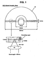
- Fig. 1 is a view illustrating the structure of a conventional digital versatile disc (DVD).
- the DVD 10 has a thickness of 1.2 mm and a diameter of 120 mm.
- the DVD 10 includes a center hole having a diameter of 15 mm, and a clamping area having a diameter of 44 mm so that a turntable and clamper provided in an optical disc device can clamp the DVD 10.
- a data recording layer based on a pit pattern is formed on the DVD 10.
- the OL of the optical pick-up for the DVD has a numerical aperture (NA) value of 0.6.
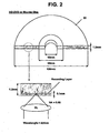
- a high-density optical disc 20 such as a high density-digital versatile disc (HD-DVD) or Blu-ray disc has a thickness of 1.2 mm and a diameter of 120 mm.
- the high-density optical disc 20 includes a center hole having a diameter of 15 mm, and a clamping area having a diameter of 44 mm so that a turntable and clamper provided in an optical disc device can clamp the high-density optical disc 20.
- OL objective lens
- the OL of the optical pick-up for the high-density optical disc has a relatively larger NA value of 0.85, in comparison with the OL of the optical pick-up for the general DVD.
- the high-density optical disc uses a laser beam having a relatively shorter wavelength in comparison with the general DVD. That is, a laser beam having a wavelength of 650 nm is used for the general DVD 10, while a laser beam having a wavelength of 405 nm is used for the high-density optical disc so that the high-density recording data can be reproduced or recorded.
- the optical disc device employs a laser beam having a relatively shorter wavelength, and enables an NA value for the OL to be increased, thereby forming a small beam spot of the laser beam, having an increased light intensity, on the high-density recording layer. Further, an optical transmission layer transmitting a laser beam having a short wavelength can be reduced. Hence, variations of the laser beam's properties and aberration occurrence can be minimized.
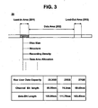
- the high-density disc includes a lead-in area 201, data area 202 and lead-out area 203.
- lead-in area are recorded major information needed for recording or reproducing data of the high-density optical disc, e.g., information associated with a size of the disc, a disc structure, a data recording density, a data area allocation, etc.
- the major information recorded in the lead-in area 201 is first read and confirmed.
- the optical disc device refers to the major information and then performs a sequence of reproduction or recording operations for reproducing data recorded in the data area 202 or recording data in the data area 202.
- a channel bit length and data bit length are 80.00 nm and 120 nm in the case of a 23.3 GB high-density optical disc, respectively.
- the channel bit length and data bit length are 74.5 nm and 111. 75 nm, respectively.
- the channel bit length and data bit length are 69.00 nm and 103.50 nm, respectively.
- Minimum mark/space lengths of data recorded in the areas 201, 202 and 203 are the same as each other.
- the optical disc device must first and correctly read and confirm the major information recorded in the lead-in area so that the data of the high-density optical disc is reproduced or recorded. At this time, the interference between a mark and space may occur in high-density recording data. Further, scratches or dust on the surface of the optical disc can adversely affect the recording and reproduction of high-density recording data. For this reason, there are problems in that the major information cannot be appropriately read and hence a data reproduction or recording operation cannot be appropriately performed.
- an optical disk comprising the features of the preambles of independent claims 1 and 3. Furthermore, this document suggests the features of the preamble of independent method claim 9.
- an optical disk has one or more recording tracks formed concentrically or spirally to the disk to which data signals are recorded by forming different-length marks and spaces on the tracks.
- An ID signal combining marks and spaces of two or more predetermined lengths approximately equal to the length of the marks and spaces forming the data signals is recorded to the recording tracks within a predetermined disk area, creating the ID signal by aligning the marks and spaces in the radial direction and recording the aligned marks and spaces to adjacent tracks in a predetermined radial disk area.
- the ID signal may be used to provide basic disk information, such as the identification of the disk type.
- the present invention has been made in view of the above problems of the prior art, and it is the object of the present invention to provide a high-density optical disc, and a method for recording data thereon, which can allow an optical disc device to correctly read and confirm control information recorded in a lead-in area included in the high-density optical disc such as a high density-digital versatile disc (HD-DVD) or Blu-ray disc.
- a high-density optical disc such as a high density-digital versatile disc (HD-DVD) or Blu-ray disc.
- a high-density optical disc comprising: a lead-in area; a data area; and a lead-out area, wherein a minimum mark or space length of data recorded in the lead-in area is longer than that of data recorded in the data area.
- the minimum mark or space length of the data recorded in the lead-in area may be the same as or longer than a valid diameter of a laser beam spot.
- the lead-out area may comprise at least one data item being the same as the data recorded in the lead-in area, and the minimum mark or space length of the data copied to the lead-out area may be the same as that of the data recorded in the lead-in area.
- the high-density optical disc may further comprise a specified area in which information associated with the minimum mark or space of the data recorded in the lead-in area and data area is recorded.
- a method for reproducing or recording data of a high-density optical disc comprising the steps of: (a) detecting a rotation velocity of a spindle motor in a procedure of reading data recorded in a lead-in area and comparing the detected rotation velocity with a predetermined reference rotation velocity; and (b) applying a reproduction processing algorithm to reproduce the data recorded in the lead-in area based on the result of the step (a).
- a method for reproducing or recording data of a high-density optical disc comprising the steps of: (a) reading the information items associated with the minimum mark or space lengths of the data recorded in a lead-in area and data area from the specified area and comparing the information items; and (b) applying a reproduction processing algorithm to reproduce the data recorded in the lead-in area based on the result of step (a).
- a method for recording information on an optical recording medium which includes lead-in area, user data area, and lead-out area, comprising the steps of: (a) recording, in the user data area, data to be recorded according to a control signal from controller; (b) recording, in lead-in area or lead-out area, first control information to control reproduction of the recorded data in the user data area; and (c) recording, in an area other than the lead-in, the lead-out, and the user data area, second control information to control reproduction of the recorded data in the lead-in or lead-out area, wherein the second control information is to indicate a minimum length of mark or space recorded in user data area and a minimum length of mark or space in the lead-in or lead-out area respectively.
- a method for recording information on an optical recording medium which includes lead-in area, user data area, and lead-out area, comprising the steps of: (a) recording, in the user data area, data to be recorded according to a control signal from controller; and (b) recording, in a specified area other than the user data area, control information to control reproduction of the recorded data in the user data area, wherein the control information includes information for indicating a minimum length of mark or space recorded in user data area and a minimum length of mark or space in the lead-in or lead-out area respectively.
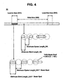
- Fig. 4 is a view illustrating a state where data having different minimum mark/space lengths are recorded in a lead-in area and data area provided in a high-density optical disc in accordance with the present invention.
- a high-density optical disc 30 such as a high density-digital versatile disc (HD-DVD) or Blu-ray disc includes a lead-in area 301, data area 302 and lead-out area 303.
- major information needed for recording or reproducing data of the high-density optical disc e.g., information associated with a size of the disc, a disc structure, a data recording density, a data area allocation, etc.
- a minimum mark/space length of the major information recorded in the lead-in area 301 is longer than that of general video and audio data recorded in the data area 302.
- the minimum mark length (Minimum Mark_LIA) of the major information recorded in the lead-in area 301 is longer than the minimum mark length (Minimum Mark_DA) of the general video and audio data recorded in the data area 302.
- the length of a minimum mark recorded in the lead-in area 301 is the same as or longer than a valid diameter of a beam spot depending upon the NA associated with an objective lens for the high-density optical disc and the wavelength ⁇ of a laser beam.
- Equation 1 0.83 is a coefficient, ⁇ is the wavelength of a laser beam, and NA is a numerical aperture value.
- the minimum mark length of the major information recorded in the lead-in area 301 is the same as or longer than the valid diameter 395 nm of the laser beam spot. Further, the minimum mark length of the major information recorded in the lead-in area 301 is longer than the minimum mark length of the video and audio data recorded in the data area 302. In this case, the minimum space length (Minimum Space_LIA) of the major information recorded in the lead-in area 301 is the same as or longer than the valid diameter 395 nm of the laser beam spot. The minimum space length of the major information recorded in the lead-in area 301 is longer than the minimum mark length (Minimum Space_DA) of the video and audio data recorded in the data area 302.
- the high-density optical disc can have three types of recording densities.
- the three types of recording densities based on a single layer include 23.305 Gbytes, 25.025 Gbytes and 27.020 Gbytes.
- a channel bit length corresponding to each recording density i.e., a length of "1T" is 80.00 nm in the case of 23.305 Gbytes.
- the length of "1T” is 74.50 nm in the case of 25.025 Gbytes.
- the length of "1T” is 69.00 nm in the case of 27.020 Gbytes.
- a mark or space of data to be recorded in the data area has a length of "2T" to "8T” .
- the minimum mark or space length of data to be recorded in the lead-in area is the same as or longer than the valid diameter of the beam spot, a mark or space having a length of "5T" or more can be recorded as data of the lead-in area.
- a method for modulating data to be recorded in the lead-in area can be changed in order that a mark or space having a length of "5T” to "8T” or a length of "5T” to "11T” can be recorded. Further, in a state where the method for modulating data to be recorded in the lead-in area is the same as a method for modulating data to be recorded in the data area, the lengths of other marks or spaces can be increased in proportion to the increased minimum mark or space length.
- a length of "2T” in the data area corresponds to a length of "5T” in the lead-in area
- a length of "3T” in the data area corresponds to a length of "7.5T” in the lead-in area
- a length of "8T” in the data area corresponds to a length of "20T” in the lead-in area.
- the data modulation method for the lead-in area containing data of a mark or space having the minimum mark or space length of "5T” or longer is different from the data modulation method for the data area, for example, where the data in the lead-in area is modulated using marks or spaces based on only four types of "5T", “6T”, “7T” and “8T” or using marks or spaces based on lengths of "5T” to "11T” , there is a merit in that less of the space of the lead-in area is occupied.
- a new modulation method must be designed and a new reproduction device for performing a demodulation method corresponding to the new modulation method is additionally needed in the optical disc system.
- the minimum mark or space length of data recorded in the lead-in area is longer than that of data recorded in the data area or where disc data based on the different data modulation methods associated with the lead-in area and data area is reproduced or recorded
- information associated with the lead-in area of the disc needs to be recognized so that the lead-in area containing information needed for reproducing or recording the disc data can be appropriately read. That is, when a minimum mark or space length of data or a data modulation type of the lead-in area is recognized, the data recorded in the lead-in area can be appropriately read.
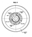
- the information associated with the lead-in area needs to be recorded in a specified area, formed inner than the lead-in area, to be first read when the disc is inserted in the optical disc device. As shown in Fig. 6 , there is formed a burst cutting area (BCA) inner than the lead-in area. So it is preferable that the information associated with the lead-in area is recorded in the BCA to be first read.
- BCA burst cutting area
- the data recorded in the lead-in area can be appropriately reproduced using the information, associated with the lead-in area, recorded in the specified area as described above.
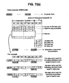
- Figs. 7A and 7B show a data structure and data contents associated with BCA code.
- information indicating the minimum mark or space length of the lead-in area can be recorded in the 2 nd data unit.
- Information indicating the minimum mark or space length of the data area can be recorded in the 3 rd data unit.
- Information indicating a data modulation type for the lead-in area can be recorded in the 4 th data unit.
- "b1b0" and "b7b6b5b4b3b2" of the 1 st byte I 0,1 contained in the 2 nd data unit can be "01" and "000010", respectively.
- the remaining 15 bytes contained in the 2 nd data unit can be used for indicating the minimum mark or space length of the lead-in area.
- "b1b0” and “b7b6b5b4b3b2" of the 1 st byte I 0,2 contained in the 3 rd data unit can be “10” and "000010", respectively.
- the remaining 15 bytes contained in the 3 rd data unit can be used for indicating the minimum mark or space length of the data area.
- "b1b0” and “b7b6b5b4b3b2" of the 1 st byte I 0,3 contained in the 4 th data unit can be "11” and "000010", respectively.
- the remaining 15 bytes contained in the 4 th data unit can be used for indicating the data modulation type.
- Fig. 8 is a view illustrating a system for recording and reproducing data of the high-density optical disc in accordance with the present invention.
- the system includes a high-density optical disc 50; an optical pick-up 60 for picking up data from the optical disc 50 or recording on the optical disc 50; a radio frequency (RF) processor for shaping a waveform of data read by the optical pick-up 60; a digital signal processor (DSP) 70 for converting data reproduced by the RF processor in a digital manner to demodulate the data at a time of reproducing the data or modulating data at a time of recording the data; a buffer memory 80 for temporarily storing the data; and a controller 90 for controlling the above-described components of the system.
- RF radio frequency
- DSP digital signal processor
- the DSP 70 can include a processor 71 for the data area based on a default demodulation and reproduction signal processing method appropriate for reproducing general data recorded in the data area of the high-density optical disc; and a processor 72 for the lead-in area based on another demodulation and reproduction signal processing method appropriate for reproducing data in a state where the minimum mark or space length of the lead-in area has been lengthened or the data of the lead-in area has been especially modulated.
- the controller 90 When the optical disc 50 is loaded in the system and data of the optical disc 50 read by the optical pick-up 60 is inputted into the DSP 70 through the RF processor, the controller 90 preferably performs a control operation such that the demodulation and reproduction signal processing method appropriate for reproducing the data recorded in the lead-in area can be selected using information, associated with the lead-in area, recorded in the innermost area of the optical disc 50.
- the optical disc device for reproducing or recording data of the high-density optical disc can more correctly read and confirm major information recorded in the lead-in area.
- the interference between a mark and space in the high-density recording data can be minimized, and the effects of scratches or dust can be reduced. For this reason, an erroneous data reproduction or recording operation can be effectively prevented.
- the major information of the lead-in area can be copied to the lead-out area 403 as shown in Fig. 5 .
- the general disc reproduction or recording device When the disc is loaded, the general disc reproduction or recording device performs an operation of reading major information recorded in the lead-in area of the disc and storing the read information in a memory. As the disc reproduction or recording device rotates a spindle motor to maintain a constant user data bit rate, a constant linear velocity is maintained in the lead-in area, the data area, an inner area or an outer area.
- a linear velocity associated with a disc rotation for reading the data of the lead-in area equals that associated with the disc rotation for reading the data of the data area.
- the rotation velocity of the spindle motor can be predicted when the lead-in area located within a predetermined radius of the optical disc is read.
- the rotation velocity of the spindle motor for reading the data of the lead-in area becomes faster than the predicted rotation velocity.
- a modulation method is changed or a demodulation method such as a partial response maximum likelihood (PRML) or Viterbi-related demodulation method used in a communication system is used in order that the read signal can be appropriately demodulated and reproduced.
- PRML partial response maximum likelihood
- Viterbi-related demodulation method used in a communication system is used in order that the read signal can be appropriately demodulated and reproduced.
- the demodulation method for reproducing the read signal is applied for only processing data modulated by the corresponding modulation method.
- the above-described demodulation method cannot be applied where the data is modulated by a different modulation method or the characteristic of the optical transfer function is changed.
- the mark or space length of the lead-in area is different from that of the data area, the characteristics of optical transfer functions associated with the lead-in area and data area are different. For this reason, different signal processing methods must be applied for the different areas when the read signal is demodulated and reproduced.
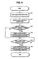
- Fig. 9 is a flowchart illustrating a method for recording and reproducing the data of the high-density optical disc in accordance with the first embodiment of the present invention.
- the device detects the rotation velocity of a spindle motor while rotating the disc on the basis of a linear velocity for reading data recorded in the lead-in area at a user data bit rate at step S11.
- the device compares the detected rotation velocity with a predetermined reference rotation velocity at step S12.
- the predetermined reference rotation velocity is the velocity needed in order for data in lead-in area the minimum mark or space length of which is same as that of data in data area to be read at the user data bit rate.
- the detected rotation velocity is higher than the reference rotation velocity, it is determined that the minimum mark or space length of data recorded in the lead-in area is longer than that of data recorded in the data area.
- the device reads the lead-in area using a new reproduction processing method to reproduce data of the lead-in area having the minimum mark or space being relatively longer at step S13. Then, the device determines whether data recorded in the lead-in area has been completely read at step S14. If the data recorded in the lead-in area has been completely read, the reproduction processing method is switched to a default reproduction processing method for reproducing data recorded in the data area and then performs a reproduction or recording operation at step S15.
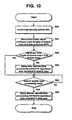
- Fig. 10 is a flowchart illustrating a method for recording and reproducing the data of the high-density optical disc in accordance with the second embodiment of the present invention.
- the device When the high-density optical disc having a specified area in which information items associated with the minimum marks or spaces of a lead-in area and data area are recorded, is inserted and seated in an optical disc reproduction or recording device at step S20, the device reads the information items associated with the minimum mark or space lengths of the areas from the specified area of the optical disc at step S21. The device compares values of the information items at step S22. If the minimum mark or space length of the lead-in area is longer than that of the data area as a result of the comparison, the device reads the lead-in area using a new reproduction processing method for reproducing the data of the lead-in area having the minimum mark or space being relatively longer at step S23.
- the device determines whether the data recorded in the lead-in area has been completely read at step S24. If the data recorded in the lead-in area has been completely read, the device switches the reproduction processing method to a default reproduction processing method for reproducing the data recorded in the data area, and performs a reproduction or recording operation at step S25.
- the above-described two methods for reproducing and recording data of the high-density optical disc in accordance with the two embodiments of the present invention can selectively use a separate reproduction or demodulation method for reproducing the data recorded in the lead-in area and a default reproduction or demodulation method for reproducing the data recorded in the data area.
- the device determines whether the major information is appropriately read in a procedure of first reading and confirming the major information recorded in the lead-in area 401. At this time, if the major information is not appropriately confirmed, the device moves an optical pick-up to the lead-out area 403 and then reads the major information copied to the lead-out area 403. In this procedure, the device determines whether the major information copied to the lead-out area 403 is appropriately read. If the major information copied to the lead-out area 403 is not appropriately read, the device determines that an error of a reproduction or recording operation for the inserted disc occurs. Then, the device terminates the operation. On the other hand, if the major information recorded in the lead-in or lead-out area is appropriately read, the device can appropriately perform a sequence of reproduction or recording operations for reading/reproducing or recording data of the data area 402.
- the present invention has been described on the basis of the disc data reproduction.
- the present invention can be applied for a method and device for recording, in the specified area, information needed for reproducing data recorded in the lead-in area or optically modulating a mark or space of the lead-in area having a minimum length different from a minimum mark or space length of the data area.
- the present invention can be easily applied for mastering equipment. That is, the present invention can be extended to a method for manufacturing a disc having a specified area in which identification information associated with a lead-in area is recorded so that the data of the lead-in area can be appropriately read in a state where the minimum mark or space length of data of the lead-in area is longer than that of data of the data area.
- the present invention provides a high-density optical disc and a method for reproducing or recording data thereof, which can allow an optical disc device to correctly read and confirm major information from the high-density optical disc, minimize the interference between a mark and space in high-density recording data, reduce the effects of scratches or dust on the disc, and efficiently prevent an erroneous data reproduction or recording operation.
Abstract
Description
- The present invention relates to a high-density optical disc such as a high density-digital versatile disc (HD-DVD) or Blu-ray disc, which includes a lead-in area, data area and lead-out area.
-
Fig. 1 is a view illustrating the structure of a conventional digital versatile disc (DVD). TheDVD 10 has a thickness of 1.2 mm and a diameter of 120 mm. TheDVD 10 includes a center hole having a diameter of 15 mm, and a clamping area having a diameter of 44 mm so that a turntable and clamper provided in an optical disc device can clamp theDVD 10. - A data recording layer based on a pit pattern is formed on the
DVD 10. There is a distance of approximately 0.6 mm between the data recording layer and the surface of an optical transmission layer, which is arranged between the data recording layer and an objective lens (OL) of an optical pick-up provided in the optical disc device. The OL of the optical pick-up for the DVD has a numerical aperture (NA) value of 0.6. - As shown in
Fig. 2 , a high-densityoptical disc 20 such as a high density-digital versatile disc (HD-DVD) or Blu-ray disc has a thickness of 1.2 mm and a diameter of 120 mm. The high-densityoptical disc 20 includes a center hole having a diameter of 15 mm, and a clamping area having a diameter of 44 mm so that a turntable and clamper provided in an optical disc device can clamp the high-densityoptical disc 20. There is a distance of approximately 0.1 mm between a data recording layer and the surface of an optical transmission layer, which is arranged between the data recording layer and an objective lens (OL) of an optical pick-up provided in the optical disc device. - The OL of the optical pick-up for the high-density optical disc has a relatively larger NA value of 0.85, in comparison with the OL of the optical pick-up for the general DVD. In order for high-density recording data to be reproduced or recorded, the high-density optical disc uses a laser beam having a relatively shorter wavelength in comparison with the general DVD. That is, a laser beam having a wavelength of 650 nm is used for the
general DVD 10, while a laser beam having a wavelength of 405 nm is used for the high-density optical disc so that the high-density recording data can be reproduced or recorded. - Thus, in a state where the OL of the optical pick-up for the high-density optical disc is closer to the recording layer of the high-density optical disc, the optical disc device employs a laser beam having a relatively shorter wavelength, and enables an NA value for the OL to be increased, thereby forming a small beam spot of the laser beam, having an increased light intensity, on the high-density recording layer. Further, an optical transmission layer transmitting a laser beam having a short wavelength can be reduced. Hence, variations of the laser beam's properties and aberration occurrence can be minimized.
- As shown in
Fig. 3 , the high-density disc includes a lead-inarea 201,data area 202 and lead-outarea 203. In the lead-in area, are recorded major information needed for recording or reproducing data of the high-density optical disc, e.g., information associated with a size of the disc, a disc structure, a data recording density, a data area allocation, etc. - Therefore, when the high-density
optical disc 20 is inserted and seated within the optical disc device, the major information recorded in the lead-inarea 201 is first read and confirmed. The optical disc device refers to the major information and then performs a sequence of reproduction or recording operations for reproducing data recorded in thedata area 202 or recording data in thedata area 202. - In the lead-in
area 201,data area 202 and lead-outarea 203, a channel bit length and data bit length are 80.00 nm and 120 nm in the case of a 23.3 GB high-density optical disc, respectively. In the case of a 25 GB high-density optical disc, the channel bit length and data bit length are 74.5 nm and 111. 75 nm, respectively. In the case of a 27 GB high-density optical disc, the channel bit length and data bit length are 69.00 nm and 103.50 nm, respectively. Minimum mark/space lengths of data recorded in theareas - As described above, the optical disc device must first and correctly read and confirm the major information recorded in the lead-in area so that the data of the high-density optical disc is reproduced or recorded. At this time, the interference between a mark and space may occur in high-density recording data. Further, scratches or dust on the surface of the optical disc can adversely affect the recording and reproduction of high-density recording data. For this reason, there are problems in that the major information cannot be appropriately read and hence a data reproduction or recording operation cannot be appropriately performed.
- Prior
art document EP 0 768 647 Al discloses an optical disk comprising the features of the preambles ofindependent claims 1 and 3. Furthermore, this document suggests the features of the preamble of independent method claim 9. According to this document, an optical disk has one or more recording tracks formed concentrically or spirally to the disk to which data signals are recorded by forming different-length marks and spaces on the tracks. An ID signal combining marks and spaces of two or more predetermined lengths approximately equal to the length of the marks and spaces forming the data signals is recorded to the recording tracks within a predetermined disk area, creating the ID signal by aligning the marks and spaces in the radial direction and recording the aligned marks and spaces to adjacent tracks in a predetermined radial disk area. The ID signal may be used to provide basic disk information, such as the identification of the disk type. - The present invention has been made in view of the above problems of the prior art, and it is the object of the present invention to provide a high-density optical disc, and a method for recording data thereon, which can allow an optical disc device to correctly read and confirm control information recorded in a lead-in area included in the high-density optical disc such as a high density-digital versatile disc (HD-DVD) or Blu-ray disc.
- The above object is solved by the combination of features of
independent claims - There is disclosed a high-density optical disc, comprising: a lead-in area; a data area; and a lead-out area, wherein a minimum mark or space length of data recorded in the lead-in area is longer than that of data recorded in the data area.
- In accordance with the above high-density optical the minimum mark or space length of the data recorded in the lead-in area may be the same as or longer than a valid diameter of a laser beam spot.
- In accordance with the above high-density optical disc, the lead-out area may comprise at least one data item being the same as the data recorded in the lead-in area, and the minimum mark or space length of the data copied to the lead-out area may be the same as that of the data recorded in the lead-in area.
- Where a minimum mark or space length of data recorded in the lead-in area is longer than that of data recorded in the data area in accordance with the above high-density optical disc, the high-density optical disc may further comprise a specified area in which information associated with the minimum mark or space of the data recorded in the lead-in area and data area is recorded.
- There is further disclosed a method for reproducing or recording data of a high-density optical disc, comprising the steps of: (a) detecting a rotation velocity of a spindle motor in a procedure of reading data recorded in a lead-in area and comparing the detected rotation velocity with a predetermined reference rotation velocity; and (b) applying a reproduction processing algorithm to reproduce the data recorded in the lead-in area based on the result of the step (a).
- There is further disclosed a method for reproducing or recording data of a high-density optical disc, comprising the steps of: (a) reading the information items associated with the minimum mark or space lengths of the data recorded in a lead-in area and data area from the specified area and comparing the information items; and (b) applying a reproduction processing algorithm to reproduce the data recorded in the lead-in area based on the result of step (a).
- There is further disclosed a method for recording information on an optical recording medium which includes lead-in area, user data area, and lead-out area, comprising the steps of: (a) recording, in the user data area, data to be recorded according to a control signal from controller; (b) recording, in lead-in area or lead-out area, first control information to control reproduction of the recorded data in the user data area; and (c) recording, in an area other than the lead-in, the lead-out, and the user data area, second control information to control reproduction of the recorded data in the lead-in or lead-out area, wherein the second control information is to indicate a minimum length of mark or space recorded in user data area and a minimum length of mark or space in the lead-in or lead-out area respectively.
- There is further disclosed a method for recording information on an optical recording medium which includes lead-in area, user data area, and lead-out area, comprising the steps of: (a) recording, in the user data area, data to be recorded according to a control signal from controller; and (b) recording, in a specified area other than the user data area, control information to control reproduction of the recorded data in the user data area, wherein the control information includes information for indicating a minimum length of mark or space recorded in user data area and a minimum length of mark or space in the lead-in or lead-out area respectively.
- The accompanying drawings, which are included to provide a further understanding of the invention, illustrate the preferred embodiments of the invention, and together with the description, serve to explain the principles of the present invention.
-
Fig. 1 is a view illustrating the structure of a conventional digital versatile disc (DVD); -
Fig. 2 is a view illustrating the structure of a conventional high-density optical disc such as a high density-digital versatile disc (HD-DVD) or Blu-ray disc; -
Fig. 3 is a view illustrating a lead-in area, data area and lead-out area provided in the conventional high-density optical disc; -
Fig. 4 is a view illustrating a state where data having different minimum mark/space lengths are recorded in a lead-in area and data area provided in a high-density optical disc in accordance with the present invention; -
Fig. 5 is a view illustrating a state where major information recorded in the lead-in area included in the high-density optical disc is copied to the lead-out area in accordance with the present invention; -
Fig. 6 is a view illustrating a burst cutting area (BCA) of the conventional high-density optical disc; -
Figs. 7 (a) and7 (b) are views illustrating a data structure and data contents of BCA code for the conventional high-density optical disc; -
Fig. 8 is a view illustrating a system for recording and reproducing data of the high-density optical disc in accordance with the present invention; -
Fig. 9 is a flowchart illustrating a method for recording and reproducing the data of the high-density optical disc in accordance with the first embodiment of the present invention; and -
Fig. 10 is a flowchart illustrating a method for recording and reproducing the data of the high-density optical disc in accordance with the second embodiment of the present invention. - Features, elements, and aspects of the invention that are referenced by the same numerals in different figures represent the same, equivalent, or similar features, elements, or aspects in accordance with one or more embodiments.
- Preferred embodiments of a high-density optical disc and a method for reproducing or recording data thereof in accordance with the present invention will be described in detail with reference to the annexed drawings.
-
Fig. 4 is a view illustrating a state where data having different minimum mark/space lengths are recorded in a lead-in area and data area provided in a high-density optical disc in accordance with the present invention. For example, a high-densityoptical disc 30 such as a high density-digital versatile disc (HD-DVD) or Blu-ray disc includes a lead-inarea 301,data area 302 and lead-outarea 303. In the lead-inarea 301 are recorded major information needed for recording or reproducing data of the high-density optical disc, e.g., information associated with a size of the disc, a disc structure, a data recording density, a data area allocation, etc. A minimum mark/space length of the major information recorded in the lead-inarea 301 is longer than that of general video and audio data recorded in thedata area 302. - For example, as shown in
Fig. 4 , the minimum mark length (Minimum Mark_LIA) of the major information recorded in the lead-inarea 301 is longer than the minimum mark length (Minimum Mark_DA) of the general video and audio data recorded in thedata area 302. The length of a minimum mark recorded in the lead-inarea 301 is the same as or longer than a valid diameter of a beam spot depending upon the NA associated with an objective lens for the high-density optical disc and the wavelength λ of a laser beam. - As given by the following
Equation 1, the valid diameter of the laser beam spot becomes approximately 395 nm where NA = 0.85 and λ = 405 nm (0.405 µm).
- In the above-described
Equation 1, 0.83 is a coefficient, λ is the wavelength of a laser beam, and NA is a numerical aperture value. - Accordingly, the minimum mark length of the major information recorded in the lead-in
area 301 is the same as or longer than the valid diameter 395 nm of the laser beam spot. Further, the minimum mark length of the major information recorded in the lead-inarea 301 is longer than the minimum mark length of the video and audio data recorded in thedata area 302. In this case, the minimum space length (Minimum Space_LIA) of the major information recorded in the lead-inarea 301 is the same as or longer than the valid diameter 395 nm of the laser beam spot. The minimum space length of the major information recorded in the lead-inarea 301 is longer than the minimum mark length (Minimum Space_DA) of the video and audio data recorded in thedata area 302. - Referring to the table shown in
Fig. 3 , for example, the high-density optical disc can have three types of recording densities. The three types of recording densities based on a single layer include 23.305 Gbytes, 25.025 Gbytes and 27.020 Gbytes. A channel bit length corresponding to each recording density, i.e., a length of "1T" is 80.00 nm in the case of 23.305 Gbytes. Further, the length of "1T" is 74.50 nm in the case of 25.025 Gbytes. Furthermore, the length of "1T" is 69.00 nm in the case of 27.020 Gbytes. - For example, where the recording density is 23.305 Gbytes, the valid diameter 395 nm of the beam spot produced by the above-described
Equation 1 corresponds to a length of approximately 5T (395/80.00 = 4.9375 nm). A mark or space of data to be recorded in the data area has a length of "2T" to "8T" . Thus, if the minimum mark or space length of data to be recorded in the lead-in area is the same as or longer than the valid diameter of the beam spot, a mark or space having a length of "5T" or more can be recorded as data of the lead-in area. In this case, a method for modulating data to be recorded in the lead-in area can be changed in order that a mark or space having a length of "5T" to "8T" or a length of "5T" to "11T" can be recorded. Further, in a state where the method for modulating data to be recorded in the lead-in area is the same as a method for modulating data to be recorded in the data area, the lengths of other marks or spaces can be increased in proportion to the increased minimum mark or space length. - First, since the lengths of other marks or spaces can be increased in proportion to the increased minimum mark or space length where the method for modulating data to be recorded in the lead-in area is the same as the method for modulating data to be recorded in the data area, a length of "2T" in the data area corresponds to a length of "5T" in the lead-in area, a length of "3T" in the data area corresponds to a length of "7.5T" in the lead-in area, and a length of "8T" in the data area corresponds to a length of "20T" in the lead-in area. Where the lengths of "5T" to "20T" are applied in place of the lengths of "2T" to "8T" as described above, there is a drawback in that the space of an embossed area may occupy much of the lead-in area. However, this drawback does not need to be seriously considered since the embossed area conventionally has sufficient space for recording the disc-related major information. There is a merit in that a load of an optical disc system can be reduced where the same data modulation methods for the lead-in area and data area are used.
- On the other hand, where the data modulation method for the lead-in area containing data of a mark or space having the minimum mark or space length of "5T" or longer is different from the data modulation method for the data area, for example, where the data in the lead-in area is modulated using marks or spaces based on only four types of "5T", "6T", "7T" and "8T" or using marks or spaces based on lengths of "5T" to "11T" , there is a merit in that less of the space of the lead-in area is occupied. However, there is a drawback in that a new modulation method must be designed and a new reproduction device for performing a demodulation method corresponding to the new modulation method is additionally needed in the optical disc system.
- As described above, where the minimum mark or space length of data recorded in the lead-in area is longer than that of data recorded in the data area or where disc data based on the different data modulation methods associated with the lead-in area and data area is reproduced or recorded, information associated with the lead-in area of the disc needs to be recognized so that the lead-in area containing information needed for reproducing or recording the disc data can be appropriately read. That is, when a minimum mark or space length of data or a data modulation type of the lead-in area is recognized, the data recorded in the lead-in area can be appropriately read.
- The information associated with the lead-in area needs to be recorded in a specified area, formed inner than the lead-in area, to be first read when the disc is inserted in the optical disc device. As shown in
Fig. 6 , there is formed a burst cutting area (BCA) inner than the lead-in area. So it is preferable that the information associated with the lead-in area is recorded in the BCA to be first read. The data recorded in the lead-in area can be appropriately reproduced using the information, associated with the lead-in area, recorded in the specified area as described above. - Further,
Figs. 7A and7B show a data structure and data contents associated with BCA code. For example, information indicating the minimum mark or space length of the lead-in area can be recorded in the 2nd data unit. Information indicating the minimum mark or space length of the data area can be recorded in the 3rd data unit. Information indicating a data modulation type for the lead-in area can be recorded in the 4th data unit. In this case, "b1b0" and "b7b6b5b4b3b2" of the 1st byte I0,1 contained in the 2nd data unit can be "01" and "000010", respectively. The remaining 15 bytes contained in the 2nd data unit can be used for indicating the minimum mark or space length of the lead-in area. Similarly, "b1b0" and "b7b6b5b4b3b2" of the 1st byte I0,2 contained in the 3rd data unit can be "10" and "000010", respectively. The remaining 15 bytes contained in the 3rd data unit can be used for indicating the minimum mark or space length of the data area. Similarly, "b1b0" and "b7b6b5b4b3b2" of the 1st byte I0,3 contained in the 4th data unit can be "11" and "000010", respectively. The remaining 15 bytes contained in the 4th data unit can be used for indicating the data modulation type. -
Fig. 8 is a view illustrating a system for recording and reproducing data of the high-density optical disc in accordance with the present invention. - The system includes a high-density
optical disc 50; an optical pick-up 60 for picking up data from theoptical disc 50 or recording on theoptical disc 50; a radio frequency (RF) processor for shaping a waveform of data read by the optical pick-up 60; a digital signal processor (DSP) 70 for converting data reproduced by the RF processor in a digital manner to demodulate the data at a time of reproducing the data or modulating data at a time of recording the data; abuffer memory 80 for temporarily storing the data; and acontroller 90 for controlling the above-described components of the system. TheDSP 70 can include aprocessor 71 for the data area based on a default demodulation and reproduction signal processing method appropriate for reproducing general data recorded in the data area of the high-density optical disc; and aprocessor 72 for the lead-in area based on another demodulation and reproduction signal processing method appropriate for reproducing data in a state where the minimum mark or space length of the lead-in area has been lengthened or the data of the lead-in area has been especially modulated. - When the
optical disc 50 is loaded in the system and data of theoptical disc 50 read by the optical pick-up 60 is inputted into theDSP 70 through the RF processor, thecontroller 90 preferably performs a control operation such that the demodulation and reproduction signal processing method appropriate for reproducing the data recorded in the lead-in area can be selected using information, associated with the lead-in area, recorded in the innermost area of theoptical disc 50. - As the minimum mark/space length of the data recorded in the lead-in area is the same as or longer than the valid diameter of the laser beam spot, the optical disc device for reproducing or recording data of the high-density optical disc can more correctly read and confirm major information recorded in the lead-in area. Thus, the interference between a mark and space in the high-density recording data can be minimized, and the effects of scratches or dust can be reduced. For this reason, an erroneous data reproduction or recording operation can be effectively prevented.
- In preparing for the case where the scratch or dust having a certain size or larger exists on the lead-in area of the above-described high-density optical disc, the major information of the lead-in area can be copied to the lead-out
area 403 as shown inFig. 5 . - Next, there will be described the method for reproducing or recording data of the high-density optical disc in a state where the minimum mark or space length of data of the lead-in area is longer than that of data of the data area.
- When the disc is loaded, the general disc reproduction or recording device performs an operation of reading major information recorded in the lead-in area of the disc and storing the read information in a memory. As the disc reproduction or recording device rotates a spindle motor to maintain a constant user data bit rate, a constant linear velocity is maintained in the lead-in area, the data area, an inner area or an outer area.
- Thus, where the mark or space length of data recorded in the lead-in area is the same as that of data recorded in the data area, a linear velocity associated with a disc rotation for reading the data of the lead-in area equals that associated with the disc rotation for reading the data of the data area. Thus, the rotation velocity of the spindle motor can be predicted when the lead-in area located within a predetermined radius of the optical disc is read.
- However, if the mark or space length of the data recorded in the lead-in area is longer than that of the data recorded in the data area, as a linear velocity for maintaining the constant user data bit rate associated with the lead-in area is faster than that for maintaining the constant user data bit rate associated with the data area, the rotation velocity of the spindle motor for reading the data of the lead-in area becomes faster than the predicted rotation velocity.
- Meanwhile, if a data density is high, i.e., the mark or space length is short or a distance between tracks is narrow, the beam spot resolution is degraded and the characteristic of an optical transfer function is degraded, such that it is difficult for a signal read by the optical pick-up to be appropriately demodulated and reproduced. For this reason, a modulation method is changed or a demodulation method such as a partial response maximum likelihood (PRML) or Viterbi-related demodulation method used in a communication system is used in order that the read signal can be appropriately demodulated and reproduced.
- The demodulation method for reproducing the read signal is applied for only processing data modulated by the corresponding modulation method. The above-described demodulation method cannot be applied where the data is modulated by a different modulation method or the characteristic of the optical transfer function is changed. Thus, where the mark or space length of the lead-in area is different from that of the data area, the characteristics of optical transfer functions associated with the lead-in area and data area are different. For this reason, different signal processing methods must be applied for the different areas when the read signal is demodulated and reproduced.
-
Fig. 9 is a flowchart illustrating a method for recording and reproducing the data of the high-density optical disc in accordance with the first embodiment of the present invention. - When the high-density optical disc is inserted and seated in an optical disc reproduction or recording device at step S10, the device detects the rotation velocity of a spindle motor while rotating the disc on the basis of a linear velocity for reading data recorded in the lead-in area at a user data bit rate at step S11.
- The device compares the detected rotation velocity with a predetermined reference rotation velocity at step S12. Herein, the predetermined reference rotation velocity is the velocity needed in order for data in lead-in area the minimum mark or space length of which is same as that of data in data area to be read at the user data bit rate. At this time, if the detected rotation velocity is higher than the reference rotation velocity, it is determined that the minimum mark or space length of data recorded in the lead-in area is longer than that of data recorded in the data area. The device reads the lead-in area using a new reproduction processing method to reproduce data of the lead-in area having the minimum mark or space being relatively longer at step S13. Then, the device determines whether data recorded in the lead-in area has been completely read at step S14. If the data recorded in the lead-in area has been completely read, the reproduction processing method is switched to a default reproduction processing method for reproducing data recorded in the data area and then performs a reproduction or recording operation at step S15.
-
Fig. 10 is a flowchart illustrating a method for recording and reproducing the data of the high-density optical disc in accordance with the second embodiment of the present invention. - When the high-density optical disc having a specified area in which information items associated with the minimum marks or spaces of a lead-in area and data area are recorded, is inserted and seated in an optical disc reproduction or recording device at step S20, the device reads the information items associated with the minimum mark or space lengths of the areas from the specified area of the optical disc at step S21. The device compares values of the information items at step S22. If the minimum mark or space length of the lead-in area is longer than that of the data area as a result of the comparison, the device reads the lead-in area using a new reproduction processing method for reproducing the data of the lead-in area having the minimum mark or space being relatively longer at step S23. The device determines whether the data recorded in the lead-in area has been completely read at step S24. If the data recorded in the lead-in area has been completely read, the device switches the reproduction processing method to a default reproduction processing method for reproducing the data recorded in the data area, and performs a reproduction or recording operation at step S25.
- The above-described two methods for reproducing and recording data of the high-density optical disc in accordance with the two embodiments of the present invention can selectively use a separate reproduction or demodulation method for reproducing the data recorded in the lead-in area and a default reproduction or demodulation method for reproducing the data recorded in the data area.
- When the high-density
optical disc 40 having the lead-in area and lead-out area in which the same major information is recorded, is inserted and seated in the optical disc reproduction or recording device, the device determines whether the major information is appropriately read in a procedure of first reading and confirming the major information recorded in the lead-inarea 401. At this time, if the major information is not appropriately confirmed, the device moves an optical pick-up to the lead-outarea 403 and then reads the major information copied to the lead-outarea 403. In this procedure, the device determines whether the major information copied to the lead-outarea 403 is appropriately read. If the major information copied to the lead-outarea 403 is not appropriately read, the device determines that an error of a reproduction or recording operation for the inserted disc occurs. Then, the device terminates the operation. On the other hand, if the major information recorded in the lead-in or lead-out area is appropriately read, the device can appropriately perform a sequence of reproduction or recording operations for reading/reproducing or recording data of thedata area 402. - The present invention has been described on the basis of the disc data reproduction. The present invention can be applied for a method and device for recording, in the specified area, information needed for reproducing data recorded in the lead-in area or optically modulating a mark or space of the lead-in area having a minimum length different from a minimum mark or space length of the data area. In particular, the present invention can be easily applied for mastering equipment. That is, the present invention can be extended to a method for manufacturing a disc having a specified area in which identification information associated with a lead-in area is recorded so that the data of the lead-in area can be appropriately read in a state where the minimum mark or space length of data of the lead-in area is longer than that of data of the data area.
- As apparent from the above description, the present invention provides a high-density optical disc and a method for reproducing or recording data thereof, which can allow an optical disc device to correctly read and confirm major information from the high-density optical disc, minimize the interference between a mark and space in high-density recording data, reduce the effects of scratches or dust on the disc, and efficiently prevent an erroneous data reproduction or recording operation.
- Although the preferred embodiments of the present invention have been disclosed for illustrative purposes, those skilled in the art will appreciate that various modifications, additions and substitutions are possible, within the scope of the appended claims.
Claims (11)
- A recording medium, comprising:a lead-in area (301) for storing major information required to record or reproduce user data; anda user data area (302) for storing the user data;
characterised in thatthe recording medium further comprises a specified area (BCA) located inner than the lead-in area (301), storing information associated with a length of mark or space of data to be recorded or recorded in the lead-in area (301) and/or the user data area (302); andthe specific area (BCA) includes a plurality of data units, each data unit includes 16 information data bytes and 16 parity data bytes and the information is recorded in a predetermined byte position within at least one data unit;wherein the data in the lead-in area (301) and the data in the user data area (302) are formed by the same data modulation method. - The recording medium of claim 1, wherein the minimum length of mark or space of the data recorded in the lead-in area (301) is the same as or longer than a valid diameter of a laser beam spot.
- The recording medium of one of the preceding claims, wherein an optical transfer function in the lead-in area (301) is different from that of the user data area (302).
- The recording medium of one of the preceding claims, wherein the mark or space are recorded or read by an optical pickup (60) using a laser beam having a wavelength (A) of 405 nm.
- The recording medium of claim 1, wherein the specified area is a burst cutting area (BCA).
- The recording medium of claim 5, wherein the information stored in the specified burst cutting area is indicative of at least one of (A) information associated with the minimum length of mark or space of data in the lead-in area (301), (B) information associated with the minimum length of mark or space of data in the user data area (302), and (C) information needed for optically modulating a mark or space of the lead-in area.
- The recording medium of claim 1, wherein recording medium further comprises a lead-out area (303), the lead-out area (303) comprising at least one data item that is recorded in the same manner as at least one data item recorded in the lead-in area (301).
- A method for reproducing data on a recording medium, comprising the steps of:reading major information required to reproduce the data recorded in a user data area (302) from a lead-in area (301); andreproducing data recorded as mark or space in the user data area (302);
characterized in thatthe reading step further includes reading information associated with a length of mark or space of data recorded in the lead-in area (301) and/or the user data area (302) from a burst cutting area (BCA) present inner than the lead-in area (301):the burst cutting area including a plurality of data units, each data unit including 16 information data bytes and 16 parity data bytes and the information being stored in a predetermined byte position within at least one data unit; andthe reproducing step further includes reproducing the data recorded in the lead-in area (301) and/or the user data area (302) basted on the information associated with the length of mark or space;wherein the reproducing step includes processing data in the lead-in area (301) and data in the user data area by same demodulation method. - The method of claim 8, wherein the reproducing step includes reproducing the mark or space in both the lead-in area (301) area and the user data area (302), by using an optical pickup (60) including a laser beam of a wavelength (A) of 405 nm.
- An apparatus for reproducing data from a recording medium, comprising:an optical pickup (60) configured to read data recorded as mark or space in a lead-in area (301) and a user data area (302) of the recording medium; anda processor (70), coupled to the optical pickup (60), configured to reproduce the data read from the optical pick-up;
characterized in thatthe optical pickup (60) is configured to read information associated with a length of a mark or space of data to be recorded or recorded in the lead-in area (301) and the user data area (302) from a burst cutting area (BCA) present inner than the lead-in area (301); the BCA includes a plurality of data units, each data unit including 16 information data bytes and 16 parity data bytes and the information being recorded in a predetermined byte position within at least one data unit; andthe processor (70) is configured to separately process data in the lead-in area (301) and data in the user data area (302) based on the read information;wherein the processor (70) is configured to reproduce data in the lead-in area (301) and data in the user data area (302) by same demodulation method. - The apparatus of claim 10, wherein the optical pickup (60) is configured to read the mark or space in both the lead-in area (301) and the user data area (302) using a laser beam having a wavelength (λ) of 405 nm.
Applications Claiming Priority (3)
| Application Number | Priority Date | Filing Date | Title |
|---|---|---|---|
| KR20020030424 | 2002-05-30 | ||
| KR1020030032545A KR100932513B1 (en) | 2002-05-30 | 2003-05-22 | How to play and record high density optical discs and high density optical discs |
| EP03728165A EP1509910B1 (en) | 2002-05-30 | 2003-05-30 | High density optical disc and method for reproducing and recording data thereof |
Related Parent Applications (1)
| Application Number | Title | Priority Date | Filing Date |
|---|---|---|---|
| EP03728165A Division EP1509910B1 (en) | 2002-05-30 | 2003-05-30 | High density optical disc and method for reproducing and recording data thereof |
Publications (2)
| Publication Number | Publication Date |
|---|---|
| EP1858010A1 EP1858010A1 (en) | 2007-11-21 |
| EP1858010B1 true EP1858010B1 (en) | 2009-04-08 |
Family
ID=29586090
Family Applications (2)
| Application Number | Title | Priority Date | Filing Date |
|---|---|---|---|
| EP07017106A Expired - Lifetime EP1858010B1 (en) | 2002-05-30 | 2003-05-30 | Recording medium and method of recording data on a recording medium |
| EP03728165A Expired - Lifetime EP1509910B1 (en) | 2002-05-30 | 2003-05-30 | High density optical disc and method for reproducing and recording data thereof |
Family Applications After (1)
| Application Number | Title | Priority Date | Filing Date |
|---|---|---|---|
| EP03728165A Expired - Lifetime EP1509910B1 (en) | 2002-05-30 | 2003-05-30 | High density optical disc and method for reproducing and recording data thereof |
Country Status (15)
| Country | Link |
|---|---|
| US (3) | US7342871B2 (en) |
| EP (2) | EP1858010B1 (en) |
| JP (2) | JP4146425B2 (en) |
| CN (1) | CN100403412C (en) |
| AT (2) | ATE375591T1 (en) |
| AU (1) | AU2003234357B2 (en) |
| BR (1) | BR0311415A (en) |
| CA (1) | CA2486447C (en) |
| DE (2) | DE60316796T2 (en) |
| DK (1) | DK1509910T5 (en) |
| ES (2) | ES2294284T3 (en) |
| MX (1) | MXPA04011890A (en) |
| PT (1) | PT1509910E (en) |
| RU (1) | RU2346344C2 (en) |
| WO (1) | WO2003102934A1 (en) |
Families Citing this family (13)
| Publication number | Priority date | Publication date | Assignee | Title |
|---|---|---|---|---|
| KR20040048476A (en) * | 2002-12-03 | 2004-06-10 | 삼성전자주식회사 | Optical information reproducing apparatus and method |
| KR20040069750A (en) * | 2003-01-30 | 2004-08-06 | 삼성전자주식회사 | Optical information storage medium |
| JP3967691B2 (en) * | 2003-03-31 | 2007-08-29 | 株式会社東芝 | Information storage medium, information reproducing apparatus, and information recording / reproducing apparatus |
| JP2004327013A (en) | 2003-04-11 | 2004-11-18 | Nec Corp | Optical disc medium and optical disk drive |
| US20050157631A1 (en) * | 2003-12-30 | 2005-07-21 | Samsung Electronics Co., Ltd | Information storage medium and method and apparatus for reproducing information recorded on the same |
| JP2006155802A (en) * | 2004-11-30 | 2006-06-15 | Toshiba Corp | Information storage medium, stamper, management information recording apparatus, disk device, and management information reproducing method |
| JP2006209883A (en) * | 2005-01-28 | 2006-08-10 | Toshiba Corp | Optical disk system and method for deciding optical disk |
| JP2007234170A (en) * | 2006-03-02 | 2007-09-13 | Tdk Corp | Reproduction method of optical recording medium and reproduction device |
| JP2007317313A (en) * | 2006-05-26 | 2007-12-06 | Tdk Corp | Optical disk, method and system for reproducing optical disk |
| US8045434B2 (en) * | 2006-09-28 | 2011-10-25 | Mediatek Inc. | Method of accessing information stored in predetermined data area on optical disc and information reproducing apparatus thereof |
| JP2008310922A (en) | 2007-06-18 | 2008-12-25 | Toshiba Corp | Information recording medium and disk device using this medium |
| WO2009051246A1 (en) * | 2007-10-19 | 2009-04-23 | Sharp Kabushiki Kaisha | Reproducing device for optical information recording medium, and optical information recording medium |
| TWI397910B (en) * | 2009-08-24 | 2013-06-01 | Sunplus Technology Co Ltd | Erasure information marking method for burst cutting area of blu-ray disc |
Family Cites Families (31)
| Publication number | Priority date | Publication date | Assignee | Title |
|---|---|---|---|---|
| CA1316597C (en) * | 1988-07-20 | 1993-04-20 | Takeshi Yamaguchi | Magneto-optical memory apparatus and optical memory apparatus |
| JP3133509B2 (en) * | 1992-09-29 | 2001-02-13 | パイオニア株式会社 | Optical disk and optical disk drive |
| JPH07111046A (en) * | 1993-10-12 | 1995-04-25 | Matsushita Electric Ind Co Ltd | Data reproducing circuit for optical disk device |
| JPH07121875A (en) * | 1993-10-22 | 1995-05-12 | Hitachi Ltd | Optical disk and optical disk reproducing device |
| JPH07130098A (en) * | 1993-10-30 | 1995-05-19 | Victor Co Of Japan Ltd | Digital recording and reproducing method |
| JPH07220612A (en) | 1994-01-31 | 1995-08-18 | Matsushita Electric Works Ltd | Circuit breaker |
| JPH07307043A (en) * | 1994-05-10 | 1995-11-21 | Sony Corp | Optical recording and reproducing device |
| JPH07334867A (en) | 1994-06-09 | 1995-12-22 | Hitachi Ltd | High-deesity optical disk and reproducing device therefor |
| JPH08124160A (en) * | 1994-10-21 | 1996-05-17 | Sony Corp | Optical disk recording device |
| JPH08339543A (en) * | 1995-04-14 | 1996-12-24 | Toshiba Corp | Optical disk having pattern for evaluating disk |
| KR970003054A (en) | 1995-06-29 | 1997-01-28 | 구자홍 | How to determine the recording density of compact discs |
| JP4086913B2 (en) * | 1995-10-09 | 2008-05-14 | 松下電器産業株式会社 | Optical disc and optical disc playback apparatus |
| JP3103505B2 (en) * | 1996-06-26 | 2000-10-30 | 三菱電機株式会社 | Optical disk and optical disk drive |
| JP2877109B2 (en) * | 1996-12-12 | 1999-03-31 | 日本電気株式会社 | Information detection device and information detection method |
| JPH1196691A (en) * | 1997-09-25 | 1999-04-09 | Ricoh Co Ltd | Recording device and reproducing device for optical disk |
| US6694023B1 (en) * | 1997-12-29 | 2004-02-17 | Samsung Electronics Co., Ltd. | Method and apparatus for protecting copyright of digital recording medium and copyright protected digital recording medium |
| KR100255191B1 (en) * | 1997-12-31 | 2000-06-01 | 윤종용 | Disc and method for detecting kind of the disc in optical disc player |
| TW468177B (en) | 1998-08-04 | 2001-12-11 | Hitachi Ltd | Data storage method, data storage medium and data storage recording device |
| JP2001110054A (en) * | 1998-09-14 | 2001-04-20 | Toshiba Corp | Information recording system |
| AU6125299A (en) | 1998-10-21 | 2000-05-08 | Matsushita Electric Industrial Co., Ltd. | Optical information recording medium, and method and apparatus for recording andreproduction |
| US6519213B1 (en) * | 1999-06-29 | 2003-02-11 | Oak Technology, Inc. | Method and apparatus for reading data from a disk |
| JP3292298B2 (en) * | 1999-07-14 | 2002-06-17 | ソニー株式会社 | Information recording apparatus, information recording method, information recording medium, information reproducing apparatus, and information reproducing method |
| WO2001008145A1 (en) * | 1999-07-22 | 2001-02-01 | Sony Corporation | Optical recording medium, optical recording method, optical reproducing method, optical recording device, optical reproducing device, and optical recording/reproducing device |
| ID28801A (en) * | 1999-08-31 | 2001-07-05 | Matsushita Electric Ind Co Ltd | DISC PLAYBACK SYSTEM |
| TW561471B (en) * | 2000-01-07 | 2003-11-11 | Matsushita Electric Ind Co Ltd | Information recording disc and information reproducing system |
| JP2001307334A (en) * | 2000-04-21 | 2001-11-02 | Toshiba Corp | Information storage medium, information recording method and information reproducing method |
| JP3954280B2 (en) * | 2000-05-23 | 2007-08-08 | 株式会社東芝 | Optical disc, reproducing method and reproducing apparatus |
| KR100605359B1 (en) * | 2000-11-01 | 2006-07-28 | 삼성전자주식회사 | Viterbi detector for optical disk |
| AU2002214264A1 (en) | 2000-11-06 | 2002-05-15 | Matsushita Electric Industrial Co., Ltd. | Optical recording medium, optical recording medium production method, optical recording medium production apparatus, program, and medium |
| JP2002230787A (en) * | 2001-02-02 | 2002-08-16 | Yamaha Corp | Optical disk and optical disk device |
| TWI258135B (en) | 2002-01-25 | 2006-07-11 | Sony Corp | Information recording device and method, information reproducing device and method, recording medium, and disc recording medium |
-
2003
- 2003-05-30 AU AU2003234357A patent/AU2003234357B2/en not_active Expired
- 2003-05-30 DE DE60316796T patent/DE60316796T2/en not_active Expired - Lifetime
- 2003-05-30 EP EP07017106A patent/EP1858010B1/en not_active Expired - Lifetime
- 2003-05-30 PT PT03728165T patent/PT1509910E/en unknown
- 2003-05-30 AT AT03728165T patent/ATE375591T1/en not_active IP Right Cessation
- 2003-05-30 BR BR0311415-5A patent/BR0311415A/en not_active Application Discontinuation
- 2003-05-30 MX MXPA04011890A patent/MXPA04011890A/en active IP Right Grant
- 2003-05-30 DE DE60327118T patent/DE60327118D1/en not_active Expired - Lifetime
- 2003-05-30 JP JP2004509934A patent/JP4146425B2/en not_active Expired - Fee Related
- 2003-05-30 US US10/448,344 patent/US7342871B2/en not_active Expired - Fee Related
- 2003-05-30 AT AT07017106T patent/ATE428169T1/en not_active IP Right Cessation
- 2003-05-30 CN CNB038125781A patent/CN100403412C/en not_active Expired - Fee Related
- 2003-05-30 WO PCT/KR2003/001066 patent/WO2003102934A1/en active IP Right Grant
- 2003-05-30 EP EP03728165A patent/EP1509910B1/en not_active Expired - Lifetime
- 2003-05-30 CA CA2486447A patent/CA2486447C/en not_active Expired - Lifetime
- 2003-05-30 RU RU2004139060/28A patent/RU2346344C2/en not_active IP Right Cessation
- 2003-05-30 ES ES03728165T patent/ES2294284T3/en not_active Expired - Lifetime
- 2003-05-30 DK DK03728165T patent/DK1509910T5/en active
- 2003-05-30 ES ES07017106T patent/ES2324499T3/en not_active Expired - Lifetime
-
2007
- 2007-05-28 JP JP2007141151A patent/JP4173906B2/en not_active Expired - Fee Related
- 2007-07-25 US US11/828,274 patent/US8159922B2/en not_active Expired - Lifetime
- 2007-07-25 US US11/828,314 patent/US20070268801A1/en not_active Abandoned
Also Published As
Similar Documents
| Publication | Publication Date | Title |
|---|---|---|
| US8159922B2 (en) | High density optical disc and method for reproducing and recording data thereof | |
| US8331209B2 (en) | High-density optical disc and recording/reproducing method thereof | |
| US7315500B2 (en) | Recording medium storing link information and apparatus and method for linking data | |
| EP0838817B1 (en) | CD player | |
| JP2009004090A (en) | High-density recording medium, and method and apparatus for controlling data reproduction of high-density recording medium | |
| US7543217B2 (en) | Method of determining suitability of a recording medium for being recorded to and/or reproduced from by an apparatus | |
| CN100356472C (en) | Optical disk apparatus and method for controlling the same | |
| JP3279043B2 (en) | optical disk | |
| EP1570468A1 (en) | Optical information reproducing apparatus and method | |
| KR100932513B1 (en) | How to play and record high density optical discs and high density optical discs | |
| KR100932505B1 (en) | High Density Optical Discs and Their Playback Methods | |
| KR100846776B1 (en) | Optical disc having two or more recording layers, recording method and reproducing method therefor | |
| CN100461271C (en) | Optical recording/reproducing apparatus | |
| JP2002288849A (en) | Focus offset adjusting method |
Legal Events
| Date | Code | Title | Description |
|---|---|---|---|
| PUAI | Public reference made under article 153(3) epc to a published international application that has entered the european phase |
Free format text: ORIGINAL CODE: 0009012 |
|
| 17P | Request for examination filed |
Effective date: 20070831 |
|
| AC | Divisional application: reference to earlier application |
Ref document number: 1509910 Country of ref document: EP Kind code of ref document: P |
|
| AK | Designated contracting states |
Kind code of ref document: A1 Designated state(s): AT BE BG CH CY CZ DE DK EE ES FI FR GB GR HU IE IT LI LU MC NL PT RO SE SI SK TR |
|
| 17Q | First examination report despatched |
Effective date: 20080205 |
|
| AKX | Designation fees paid |
Designated state(s): AT BE BG CH CY CZ DE DK EE ES FI FR GB GR HU IE IT LI LU MC NL PT RO SE SI SK TR |
|
| GRAP | Despatch of communication of intention to grant a patent |
Free format text: ORIGINAL CODE: EPIDOSNIGR1 |
|
| GRAS | Grant fee paid |
Free format text: ORIGINAL CODE: EPIDOSNIGR3 |
|
| GRAA | (expected) grant |
Free format text: ORIGINAL CODE: 0009210 |
|
| AC | Divisional application: reference to earlier application |
Ref document number: 1509910 Country of ref document: EP Kind code of ref document: P |
|
| AK | Designated contracting states |
Kind code of ref document: B1 Designated state(s): AT BE BG CH CY CZ DE DK EE ES FI FR GB GR HU IE IT LI LU MC NL PT RO SE SI SK TR |
|
| REG | Reference to a national code |
Ref country code: GB Ref legal event code: FG4D |
|
| REG | Reference to a national code |
Ref country code: CH Ref legal event code: EP |
|
| REG | Reference to a national code |
Ref country code: IE Ref legal event code: FG4D |
|
| REF | Corresponds to: |
Ref document number: 60327118 Country of ref document: DE Date of ref document: 20090520 Kind code of ref document: P |
|
| PG25 | Lapsed in a contracting state [announced via postgrant information from national office to epo] |
Ref country code: SI Free format text: LAPSE BECAUSE OF FAILURE TO SUBMIT A TRANSLATION OF THE DESCRIPTION OR TO PAY THE FEE WITHIN THE PRESCRIBED TIME-LIMIT Effective date: 20090408 |
|
| REG | Reference to a national code |
Ref country code: ES Ref legal event code: FG2A Ref document number: 2324499 Country of ref document: ES Kind code of ref document: T3 |
|
| PG25 | Lapsed in a contracting state [announced via postgrant information from national office to epo] |
Ref country code: PT Free format text: LAPSE BECAUSE OF FAILURE TO SUBMIT A TRANSLATION OF THE DESCRIPTION OR TO PAY THE FEE WITHIN THE PRESCRIBED TIME-LIMIT Effective date: 20090908 Ref country code: AT Free format text: LAPSE BECAUSE OF FAILURE TO SUBMIT A TRANSLATION OF THE DESCRIPTION OR TO PAY THE FEE WITHIN THE PRESCRIBED TIME-LIMIT Effective date: 20090408 Ref country code: FI Free format text: LAPSE BECAUSE OF FAILURE TO SUBMIT A TRANSLATION OF THE DESCRIPTION OR TO PAY THE FEE WITHIN THE PRESCRIBED TIME-LIMIT Effective date: 20090408 |
|
| PG25 | Lapsed in a contracting state [announced via postgrant information from national office to epo] |
Ref country code: SE Free format text: LAPSE BECAUSE OF FAILURE TO SUBMIT A TRANSLATION OF THE DESCRIPTION OR TO PAY THE FEE WITHIN THE PRESCRIBED TIME-LIMIT Effective date: 20090708 |
|
| PG25 | Lapsed in a contracting state [announced via postgrant information from national office to epo] |
Ref country code: MC Free format text: LAPSE BECAUSE OF NON-PAYMENT OF DUE FEES Effective date: 20090531 |
|
| REG | Reference to a national code |
Ref country code: CH Ref legal event code: PL |
|
| PG25 | Lapsed in a contracting state [announced via postgrant information from national office to epo] |
Ref country code: EE Free format text: LAPSE BECAUSE OF FAILURE TO SUBMIT A TRANSLATION OF THE DESCRIPTION OR TO PAY THE FEE WITHIN THE PRESCRIBED TIME-LIMIT Effective date: 20090408 Ref country code: CZ Free format text: LAPSE BECAUSE OF FAILURE TO SUBMIT A TRANSLATION OF THE DESCRIPTION OR TO PAY THE FEE WITHIN THE PRESCRIBED TIME-LIMIT Effective date: 20090408 Ref country code: DK Free format text: LAPSE BECAUSE OF FAILURE TO SUBMIT A TRANSLATION OF THE DESCRIPTION OR TO PAY THE FEE WITHIN THE PRESCRIBED TIME-LIMIT Effective date: 20090408 Ref country code: CH Free format text: LAPSE BECAUSE OF NON-PAYMENT OF DUE FEES Effective date: 20090531 Ref country code: LI Free format text: LAPSE BECAUSE OF NON-PAYMENT OF DUE FEES Effective date: 20090531 Ref country code: RO Free format text: LAPSE BECAUSE OF FAILURE TO SUBMIT A TRANSLATION OF THE DESCRIPTION OR TO PAY THE FEE WITHIN THE PRESCRIBED TIME-LIMIT Effective date: 20090408 |
|
| PLBE | No opposition filed within time limit |
Free format text: ORIGINAL CODE: 0009261 |
|
| STAA | Information on the status of an ep patent application or granted ep patent |
Free format text: STATUS: NO OPPOSITION FILED WITHIN TIME LIMIT |
|
| PG25 | Lapsed in a contracting state [announced via postgrant information from national office to epo] |
Ref country code: SK Free format text: LAPSE BECAUSE OF FAILURE TO SUBMIT A TRANSLATION OF THE DESCRIPTION OR TO PAY THE FEE WITHIN THE PRESCRIBED TIME-LIMIT Effective date: 20090408 Ref country code: BE Free format text: LAPSE BECAUSE OF FAILURE TO SUBMIT A TRANSLATION OF THE DESCRIPTION OR TO PAY THE FEE WITHIN THE PRESCRIBED TIME-LIMIT Effective date: 20090408 |
|
| REG | Reference to a national code |
Ref country code: IE Ref legal event code: MM4A |
|
| 26N | No opposition filed |
Effective date: 20100111 |
|
| PG25 | Lapsed in a contracting state [announced via postgrant information from national office to epo] |
Ref country code: BG Free format text: LAPSE BECAUSE OF FAILURE TO SUBMIT A TRANSLATION OF THE DESCRIPTION OR TO PAY THE FEE WITHIN THE PRESCRIBED TIME-LIMIT Effective date: 20090708 |
|
| PG25 | Lapsed in a contracting state [announced via postgrant information from national office to epo] |
Ref country code: IE Free format text: LAPSE BECAUSE OF NON-PAYMENT OF DUE FEES Effective date: 20090530 |
|
| PG25 | Lapsed in a contracting state [announced via postgrant information from national office to epo] |
Ref country code: GR Free format text: LAPSE BECAUSE OF FAILURE TO SUBMIT A TRANSLATION OF THE DESCRIPTION OR TO PAY THE FEE WITHIN THE PRESCRIBED TIME-LIMIT Effective date: 20090709 |
|
| PG25 | Lapsed in a contracting state [announced via postgrant information from national office to epo] |
Ref country code: LU Free format text: LAPSE BECAUSE OF NON-PAYMENT OF DUE FEES Effective date: 20090530 |
|
| PG25 | Lapsed in a contracting state [announced via postgrant information from national office to epo] |
Ref country code: HU Free format text: LAPSE BECAUSE OF FAILURE TO SUBMIT A TRANSLATION OF THE DESCRIPTION OR TO PAY THE FEE WITHIN THE PRESCRIBED TIME-LIMIT Effective date: 20091009 |
|
| PG25 | Lapsed in a contracting state [announced via postgrant information from national office to epo] |
Ref country code: TR Free format text: LAPSE BECAUSE OF FAILURE TO SUBMIT A TRANSLATION OF THE DESCRIPTION OR TO PAY THE FEE WITHIN THE PRESCRIBED TIME-LIMIT Effective date: 20090408 |
|
| PG25 | Lapsed in a contracting state [announced via postgrant information from national office to epo] |
Ref country code: CY Free format text: LAPSE BECAUSE OF FAILURE TO SUBMIT A TRANSLATION OF THE DESCRIPTION OR TO PAY THE FEE WITHIN THE PRESCRIBED TIME-LIMIT Effective date: 20090408 |
|
| REG | Reference to a national code |
Ref country code: FR Ref legal event code: PLFP Year of fee payment: 14 |
|
| PGFP | Annual fee paid to national office [announced via postgrant information from national office to epo] |
Ref country code: NL Payment date: 20160428 Year of fee payment: 14 |
|
| REG | Reference to a national code |
Ref country code: FR Ref legal event code: PLFP Year of fee payment: 15 |
|
| REG | Reference to a national code |
Ref country code: NL Ref legal event code: MM Effective date: 20170601 |
|
| PG25 | Lapsed in a contracting state [announced via postgrant information from national office to epo] |
Ref country code: NL Free format text: LAPSE BECAUSE OF NON-PAYMENT OF DUE FEES Effective date: 20170601 |
|
| REG | Reference to a national code |
Ref country code: FR Ref legal event code: PLFP Year of fee payment: 16 |
|
| PGFP | Annual fee paid to national office [announced via postgrant information from national office to epo] |
Ref country code: IT Payment date: 20220406 Year of fee payment: 20 Ref country code: GB Payment date: 20220405 Year of fee payment: 20 Ref country code: FR Payment date: 20220413 Year of fee payment: 20 Ref country code: ES Payment date: 20220613 Year of fee payment: 20 Ref country code: DE Payment date: 20220405 Year of fee payment: 20 |
|
| REG | Reference to a national code |
Ref country code: DE Ref legal event code: R071 Ref document number: 60327118 Country of ref document: DE |
|
| REG | Reference to a national code |
Ref country code: ES Ref legal event code: FD2A Effective date: 20230606 |
|
| REG | Reference to a national code |
Ref country code: GB Ref legal event code: PE20 Expiry date: 20230529 |
|
| P01 | Opt-out of the competence of the unified patent court (upc) registered |
Effective date: 20230524 |
|
| PG25 | Lapsed in a contracting state [announced via postgrant information from national office to epo] |
Ref country code: ES Free format text: LAPSE BECAUSE OF EXPIRATION OF PROTECTION Effective date: 20230531 |
|
| PG25 | Lapsed in a contracting state [announced via postgrant information from national office to epo] |
Ref country code: GB Free format text: LAPSE BECAUSE OF EXPIRATION OF PROTECTION Effective date: 20230529 |