EP1857894A1 - Control apparatus and control method - Google Patents
Control apparatus and control method Download PDFInfo
- Publication number
- EP1857894A1 EP1857894A1 EP07009966A EP07009966A EP1857894A1 EP 1857894 A1 EP1857894 A1 EP 1857894A1 EP 07009966 A EP07009966 A EP 07009966A EP 07009966 A EP07009966 A EP 07009966A EP 1857894 A1 EP1857894 A1 EP 1857894A1
- Authority
- EP
- European Patent Office
- Prior art keywords
- controlled object
- control
- model
- controlled
- value
- Prior art date
- Legal status (The legal status is an assumption and is not a legal conclusion. Google has not performed a legal analysis and makes no representation as to the accuracy of the status listed.)
- Granted
Links
Images


Classifications
-
- G—PHYSICS
- G05—CONTROLLING; REGULATING
- G05B—CONTROL OR REGULATING SYSTEMS IN GENERAL; FUNCTIONAL ELEMENTS OF SUCH SYSTEMS; MONITORING OR TESTING ARRANGEMENTS FOR SUCH SYSTEMS OR ELEMENTS
- G05B13/00—Adaptive control systems, i.e. systems automatically adjusting themselves to have a performance which is optimum according to some preassigned criterion
- G05B13/02—Adaptive control systems, i.e. systems automatically adjusting themselves to have a performance which is optimum according to some preassigned criterion electric
- G05B13/04—Adaptive control systems, i.e. systems automatically adjusting themselves to have a performance which is optimum according to some preassigned criterion electric involving the use of models or simulators
- G05B13/041—Adaptive control systems, i.e. systems automatically adjusting themselves to have a performance which is optimum according to some preassigned criterion electric involving the use of models or simulators in which a variable is automatically adjusted to optimise the performance
-
- F—MECHANICAL ENGINEERING; LIGHTING; HEATING; WEAPONS; BLASTING
- F02—COMBUSTION ENGINES; HOT-GAS OR COMBUSTION-PRODUCT ENGINE PLANTS
- F02D—CONTROLLING COMBUSTION ENGINES
- F02D35/00—Controlling engines, dependent on conditions exterior or interior to engines, not otherwise provided for
- F02D35/02—Controlling engines, dependent on conditions exterior or interior to engines, not otherwise provided for on interior conditions
- F02D35/023—Controlling engines, dependent on conditions exterior or interior to engines, not otherwise provided for on interior conditions by determining the cylinder pressure
-
- F—MECHANICAL ENGINEERING; LIGHTING; HEATING; WEAPONS; BLASTING
- F02—COMBUSTION ENGINES; HOT-GAS OR COMBUSTION-PRODUCT ENGINE PLANTS
- F02D—CONTROLLING COMBUSTION ENGINES
- F02D41/00—Electrical control of supply of combustible mixture or its constituents
- F02D41/02—Circuit arrangements for generating control signals
- F02D41/14—Introducing closed-loop corrections
- F02D41/1401—Introducing closed-loop corrections characterised by the control or regulation method
- F02D41/1402—Adaptive control
-
- F—MECHANICAL ENGINEERING; LIGHTING; HEATING; WEAPONS; BLASTING
- F02—COMBUSTION ENGINES; HOT-GAS OR COMBUSTION-PRODUCT ENGINE PLANTS
- F02D—CONTROLLING COMBUSTION ENGINES
- F02D41/00—Electrical control of supply of combustible mixture or its constituents
- F02D41/0002—Controlling intake air
- F02D2041/001—Controlling intake air for engines with variable valve actuation
-
- F—MECHANICAL ENGINEERING; LIGHTING; HEATING; WEAPONS; BLASTING
- F02—COMBUSTION ENGINES; HOT-GAS OR COMBUSTION-PRODUCT ENGINE PLANTS
- F02D—CONTROLLING COMBUSTION ENGINES
- F02D41/00—Electrical control of supply of combustible mixture or its constituents
- F02D41/02—Circuit arrangements for generating control signals
- F02D41/14—Introducing closed-loop corrections
- F02D41/1401—Introducing closed-loop corrections characterised by the control or regulation method
- F02D2041/1413—Controller structures or design
- F02D2041/1418—Several control loops, either as alternatives or simultaneous
-
- F—MECHANICAL ENGINEERING; LIGHTING; HEATING; WEAPONS; BLASTING
- F02—COMBUSTION ENGINES; HOT-GAS OR COMBUSTION-PRODUCT ENGINE PLANTS
- F02D—CONTROLLING COMBUSTION ENGINES
- F02D41/00—Electrical control of supply of combustible mixture or its constituents
- F02D41/02—Circuit arrangements for generating control signals
- F02D41/14—Introducing closed-loop corrections
- F02D41/1401—Introducing closed-loop corrections characterised by the control or regulation method
- F02D2041/1413—Controller structures or design
- F02D2041/1432—Controller structures or design the system including a filter, e.g. a low pass or high pass filter
-
- F—MECHANICAL ENGINEERING; LIGHTING; HEATING; WEAPONS; BLASTING
- F02—COMBUSTION ENGINES; HOT-GAS OR COMBUSTION-PRODUCT ENGINE PLANTS
- F02D—CONTROLLING COMBUSTION ENGINES
- F02D41/00—Electrical control of supply of combustible mixture or its constituents
- F02D41/02—Circuit arrangements for generating control signals
- F02D41/14—Introducing closed-loop corrections
- F02D41/1401—Introducing closed-loop corrections characterised by the control or regulation method
- F02D2041/1433—Introducing closed-loop corrections characterised by the control or regulation method using a model or simulation of the system
-
- F—MECHANICAL ENGINEERING; LIGHTING; HEATING; WEAPONS; BLASTING
- F02—COMBUSTION ENGINES; HOT-GAS OR COMBUSTION-PRODUCT ENGINE PLANTS
- F02D—CONTROLLING COMBUSTION ENGINES
- F02D2200/00—Input parameters for engine control
- F02D2200/02—Input parameters for engine control the parameters being related to the engine
- F02D2200/10—Parameters related to the engine output, e.g. engine torque or engine speed
- F02D2200/1002—Output torque
-
- F—MECHANICAL ENGINEERING; LIGHTING; HEATING; WEAPONS; BLASTING
- F02—COMBUSTION ENGINES; HOT-GAS OR COMBUSTION-PRODUCT ENGINE PLANTS
- F02D—CONTROLLING COMBUSTION ENGINES
- F02D2250/00—Engine control related to specific problems or objectives
- F02D2250/18—Control of the engine output torque
-
- F—MECHANICAL ENGINEERING; LIGHTING; HEATING; WEAPONS; BLASTING
- F02—COMBUSTION ENGINES; HOT-GAS OR COMBUSTION-PRODUCT ENGINE PLANTS
- F02D—CONTROLLING COMBUSTION ENGINES
- F02D41/00—Electrical control of supply of combustible mixture or its constituents
- F02D41/0002—Controlling intake air
-
- F—MECHANICAL ENGINEERING; LIGHTING; HEATING; WEAPONS; BLASTING
- F02—COMBUSTION ENGINES; HOT-GAS OR COMBUSTION-PRODUCT ENGINE PLANTS
- F02D—CONTROLLING COMBUSTION ENGINES
- F02D41/00—Electrical control of supply of combustible mixture or its constituents
- F02D41/30—Controlling fuel injection
- F02D41/3011—Controlling fuel injection according to or using specific or several modes of combustion
- F02D41/3017—Controlling fuel injection according to or using specific or several modes of combustion characterised by the mode(s) being used
- F02D41/3035—Controlling fuel injection according to or using specific or several modes of combustion characterised by the mode(s) being used a mode being the premixed charge compression-ignition mode
Definitions
- This invention relates to a control apparatus and a control method which control a controlled object with a control algorithm using a controlled object model.
- the control apparatus controls the rotational speed of a driven shaft as a controlled variable by inputting a control input to a clutch mechanism as a controlled object, and includes a controller for calculating the control input.
- This controller calculates the control input with a target filter-type two-degree-of-freedom sliding mode control algorithm, based on a controlled object model of a discrete-time system, in which the relationship between the control input and the controlled variable is expressed by a recurrence formula.
- the control input is input to an actuator of the clutch mechanism, and the controlled variable is controlled such that it is caused to converge to its target value.
- the controller shown in FIG. 5 of the Japanese Laid-Open Patent Publication (Kokai) No. 2005-23922 includes an identifier that identifies model parameters of the controlled object with an identification algorithm, e.g. based on the sequential least-squares method.
- an identification algorithm e.g. based on the sequential least-squares method.
- the model parameters are identified onboard, and hence even when the controlled object model ceases to match the characteristics of a clutch mechanism as an actual controlled object due to variation between individual products of the clutch mechanism or aging of the same, causing a modeling error, it is possible to control the clutch mechanism while quickly compensating for the modeling error.
- the controlled object having extremal characteristics When the conventional control apparatus described above is applied to a controlled object having characteristics that a controlled variable thereof takes an extremum value (local maximum value or local minimum value) as a control input (hereinafter referred to as "the controlled object having extremal characteristics") changes, if a target value of the controlled variable is set to a value larger than the local maximum value of the controlled variable or a value smaller than the local minimum value of the same, the controlled variable cannot reach the target value, so that the control input is calculated such that the controlled variable is changed up to the maximum value or the minimum value. As a result, the controlled variable is controlled in a direction largely deviating from the target value. That is, the control system is made unstable, and the accuracy of control is largely degraded.
- the identification algorithm such as one based on the sequential least-squares method used in the above-mentioned identifier, is applicable, insofar as the controlled object model can be expressed by a recurrence formula.
- the identification algorithm is not applicable. In the case of such a controlled object, it is impossible to compensate for a modeling error, which can be undesirably caused due to variation between individual units of the controlled object and aging of the same, and hence the control accuracy is further degraded.
- the present invention has been made to provide a solution to the above-described problems, and an object thereof is to provide a control apparatus and a control method, which are capable of ensuring both high-level stability and accuracy of control, even when controlling a controlled object having extremal characteristics or a controlled object a controlled object model of which cannot be expressed by a recurrence formula.
- a control apparatus comprising correlation parameter-calculating means for using a controlled object model defining a relationship between a control input and a controlled variable in a controlled object, and thereby calculating a correlation parameter indicative of a correlation between the control input and a controlled variable in the controlled object model, target value-setting means for setting a target value as a target of the controlled variable of the controlled object, control input-calculating means for calculating the control input with a predetermined first control algorithm such that the controlled variable of the controlled object is caused to converge to the target value, and determining at least one of an increasing/decreasing rate and an increasing/decreasing direction of the control input according to the correlation parameter, and model corrector means for correcting the controlled object model such that the controlled variable of the controlled object model matches the controlled variable of the controlled object.
- the correlation parameter representative of a correlation between the control input and the controlled variable in the controlled object model is calculated.
- the control input is calculated with the predetermined first control algorithm such that the controlled variable is caused to converge to the target value, and at the same time, at least one of the increasing/decreasing rate or the increasing/decreasing direction of the control input is determined according to the correlation parameter.
- the correlation of the controlled variable to the control input varies according to the value of the control input, since the increasing/decreasing rate of the control input is determined according to the change in the correlation, it is possible to control the controlled variable such that the controlled variable converges to its target value without causing any oscillating behavior or unstable behavior. That is, it is possible to ensure high-level stability of the control.
- the increasing/decreasing direction of the control input is determined according to the correlation parameter, when controlling, for example, a controlled object the controlled variable of which has a local maximum value which it takes as the control input is varied, insofar as the target value is set to a value not larger than the local maximum value, it is possible to cause the controlled variable to converge to the target value with accuracy.
- the target value is set to a value larger than the local maximum value, assuming that as the control input is varied, the controlled variable changes past the local maximum value, the correlation between the control input and the controlled variable once increases and then decreases again, and simultaneously, there occurs a change from one of the positive and negative correlations to the other, so that the correlation parameter represents such a change in the correlation. Therefore, by changing the increasing/ decreasing direction of the control input according to the correlation parameter, it is possible to maintain the controlled variable at the local maximum value or in its vicinity.
- the controlled variable of which has a local minimum value which it takes as the control input is varied, insofar as the target value is set to a value not smaller than the local minimum value, it is possible to cause the controlled variable to converge to the target value with accuracy.
- the target value is set to a value smaller than the local minimum value, assuming that as the control input is varied, the controlled variable changes past the local minimum value, the correlation between the control input and the controlled variable once increases and then deceases again, and simultaneously, there occurs a change from one of the positive and negative correlations to the other, so that the correlation parameter represents such a change in the correlation.
- both the control stability and the control accuracy can be maintained at a high level.
- both the increasing/ decreasing rate and the increasing/decreasing direction are determined according to the correlation parameter, it is possible to obtain all the advantageous effects described above.
- the controlled object model is corrected such that the controlled variable of the controlled object model matches the controlled variable of the controlled object, and hence even when the modeling error occurs due to the variation between individual units of the controlled object and the aging of the same, it is possible to quickly accommodate the modeling error, and increase the accuracy of calculation of the correlation parameter. As a result, it is possible to improve the control accuracy.
- “calculation”, “determination”, “setting”, and “correction” as in “calculation of the correlation parameter", “calculation or determination of the control input”, “setting of the target value”, and the correction of the controlled object model” are not limited to execution of computation, determination, setting, and correction by a program, but include generating electric signals representative of them.
- the model corrector means calculates a plurality of correction parameters for use in correction of the controlled object model, in a manner associated with a plurality of regions obtained by dividing a region where the control input is variable respectively, and calculating ones of the correction parameters corresponding to ones of the regions where the calculated control input exists, with a predetermined second control algorithm, such that the controlled variable of the controlled object model matches the controlled variable of the controlled object.
- a plurality of correction parameters for use in correcting the controlled object model are calculated in a manner associated with a plurality of regions formed by dividing a region within which the control input is variable, and ones of the correction parameters corresponding to ones of the regions in which the control input exists are calculated with a predetermined second control algorithm such that the controlled variable of the controlled object model matches the controlled variable of the controlled object. Therefore, even when the modeling error is different between the regions, it is possible to correct the controlled object model on a region-by-region basis using such correction parameters respectively associated with the regions.
- the predetermined second control algorithm includes a predetermined response-specifying control algorithm.
- the correction parameters are calculated with an algorithm including a predetermined response-specifying control algorithm, such that the controlled variable of the controlled object model matches the controlled variable of the controlled object. Therefore, even in the case of controlling a non-linear controlled object the controlled object model of which cannot be expressed using a recurrence formula, it is possible to calculate the correction parameters as values that do not cause an unstable behavior, such as an oscillating behavior or overshooting, and using the correction parameters thus calculated, it is possible to control the controlled object while correcting the controlled object model. As a result, it is possible to prevent the transient response of the control system from becoming oscillatory or unstable, and improve the control accuracy during a transition period.
- the model corrector means corrects the controlled object model using values obtained by multiplying values of a plurality of functions by the correction parameters, respectively, adjacent two of the regions overlapping each other, and the functions have respective characteristics such that the functions each take the maximum value in a center or its vicinity of each of the respective associated regions and change linearly or curvilinearly, and each two of the functions corresponding to each two overlapping ones of the regions are set such that the functions intersect with each other in portions where the functions change linearly or curvilinearly.
- the controlled object model is corrected using values obtained by multiplying values of the functions by the correction parameters, respectively, and each adjacent two of the regions overlap each other.
- these functions have characteristics that with respect to the control inputs in the respective regions, they each take the maximum value in the center or its vicinity of each of the associated regions, and change linearly or curvilinearly, and are set such that each two of the functions in the respective overlapping regions intersect with each other, in portions where they change linearly or curvilinearly. Therefore, in correcting the controlled object model, it is possible to correct the same continuously over the regions of the control inputs, so that the corrected controlled object model has no discontinued points. This makes it possible to prevent the transient response of the control system from becoming temporarily unstable due to the discontinued points of the controlled object model, and further improve the control accuracy during the transient time.
- the model corrector means calculates the correction parameters using an integral value of a value based on a difference between the controlled variable of the controlled object model and the controlled variable of the controlled object, while at the same time subjecting the integral value to a predetermined forgetting process.
- the correction parameters are calculated using the integral value of the value based on the difference between the controlled variable of the controlled object model and the controlled variable of the controlled object. Therefore, unless the integral value is subjected to the forgetting process, even when the corrected control object model fully matches the actual characteristics of the controlled object, making the difference equal to 0, and the difference ceases to accurately represent the error information on the model, correction of the controlled object model is continued by the influence of the integral value. As a result, there is a fear of the controlled object model being improperly corrected.
- the integral value is calculated while subjecting the integral values to the predetermined forgetting process.
- the controlled object is an internal combustion engine.
- the controlled variable of the engine takes the extremum value with respect to the control input, insofar as the target value is in a range which can be attained by the controlled variable, it is possible to control the controlled variable of the engine without causing an oscillating behavior or unstable behavior such that it converges to the target value, and even when the controlled variable exceeds the attainable range, it is possible to maintain the controlled variable at the extremum value or in its vicinity, whereby both the control stability and the control accuracy can be secured for the engine.
- a control apparatus comprising correlation parameter-calculating means for using a controlled object model defining a relationship between a plurality of control inputs and a controlled variable in a controlled object, and thereby calculating a plurality of correlation parameters respectively indicative of correlations between the control inputs and a controlled variable in the controlled object model, target value-setting means for setting a target value as a target of the controlled variable of the controlled object, control input-calculating means for calculating each of the control inputs with a predetermined first control algorithm such that the controlled variable of the controlled object is caused to converge to the target value, and determining at least one of an increasing/decreasing rate and an increasing/decreasing direction of each control input according to each of the correlation parameters, and model corrector means for correcting the controlled object model such that the controlled variable of the controlled object model matches the controlled variable of the controlled object.
- the correlation parameters representative of correlations between the control inputs and the controlled variable in the controlled object model are calculated.
- the control inputs are each calculated with the predetermined first control algorithm such that the controlled variable is caused to converge to the target value, and at the same time, at least one of the increasing/decreasing rate or the increasing/decreasing direction of each control input is determined according to each of the correlation parameters.
- each correlation parameter e.g.
- the increasing/decreasing rate of one of the control inputs with a higher correlation is set to be larger, and the increasing/deceasing rate of the other of the control inputs with a lower correlation is set to be smaller, it is possible to cause the controlled variable to converge to the target value while suppressing interaction between the control inputs and causing them to cooperate.
- the controlled variable of which has a local maximum value which it takes as the extremizing control input is varied, insofar as the target value is set to a value not larger than the local maximum value, it is possible to cause the controlled variable to converge to the target value with accuracy.
- the target value is set to a value larger than the local maximum value, assuming that as the extremizing control input is varied, the controlled variable changes past the local maximum value, the correlation between the control input and the controlled variable once increases and then deceases again, and simultaneously, there occurs a change from one of the positive and negative correlations to the other, so that the correlation parameter associated with the extremizing control input represents such a change in the correlation.
- the controlled variable of which has a local minimum value which it takes as the extremizing control input is varied, insofar as the target value is set to a value not smaller than the local minimum value, it is possible to cause the controlled variable to converge to the target value with accuracy.
- the target value is set to a value smaller than the local minimum value, assuming that in response a change in the extremizing control input, the controlled variable changes past the local minimum value, the correlation between the extremizing control input and the controlled variable once increases and then deceases again, and simultaneously, there occurs a change from one of the positive and negative correlations to the other, so that the correlation parameter associated with the extremizing control input represents such a change in the correlation.
- the controlled object model is corrected such that the controlled variable of the controlled object model matches the controlled variable of the controlled object, and hence even when the modeling error occurs due to the variation between individual units of the controlled object and the aging of the same, it is possible to quickly accommodate the modeling error. As a result, it is possible to increase the control accuracy.
- the model corrector means calculates a plurality of correction parameters for use in correction of the controlled object model, in a manner associated with a plurality of regions obtained by dividing a region where the control inputs are variable respectively, and calculating ones of the correction parameters corresponding to ones of the regions where the calculated control inputs exist, with a predetermined second control algorithm, such that the controlled variable of the controlled object model matches the controlled variable of the controlled object.
- a plurality of correction parameters for use in correcting the controlled object model are calculated in a manner associated with a plurality of regions formed by dividing a region within which the control inputs are variable, and ones of the correction parameters corresponding to ones of the regions in which the control inputs exist are calculated with a predetermined second control algorithm such that the controlled variable of the controlled object model matches the controlled variable of the controlled object. Therefore, even when the modeling error is different between the regions, it is possible to correct the controlled object model on a region-by-region basis using such correction parameters respectively associated with the regions.
- the predetermined second control algorithm includes a predetermined response-specifying control algorithm.
- the correction parameters are calculated with an algorithm including a predetermined response-specifying control algorithm, such that the controlled variable of the controlled object model matches the controlled variable of the controlled object. Therefore, even in the case of controlling a non-linear controlled object the controlled object model of which cannot be expressed using a recurrence formula, it is possible to calculate the correction parameters as values that do not cause an unstable behavior, such as an oscillating behavior or overshooting, and using the correction parameters thus calculated, it is possible to control the controlled object while correcting the controlled object model. As a result, it is possible to prevent the transient response of the control system from becoming oscillatory or unstable, and improve the control accuracy during a transition period.
- the model corrector means corrects the controlled object model using values obtained by multiplying values of a plurality of functions by the correction parameters, respectively, adjacent two of the regions overlapping each other, and the functions have respective characteristics such that with respect to the control inputs in the regions, the functions each take the maximum value in a center or its vicinity of each of the respective associated regions and change in a planar fashion or in a curviplanar fashion, and each two of the functions corresponding to each two overlapping ones of the regions are set such that the functions intersect with each other in portions where the functions change in a planar fashion or in a curviplanar fashion.
- the controlled object model is corrected using values obtained by multiplying values of the functions by the correction parameters, respectively, and each adjacent two of the regions overlap each other.
- These functions have characteristics that with respect to the control inputs in the respective regions, they each take the maximum value in the center or its vicinity of each of the associated regions, and change in a planar fashion or in a curviplanar fashion, and are set such that each two of the functions in the respective overlapping regions intersect with each other, in portions where they change in a planar fashion or in a curviplanar fashion. Therefore, in correcting the controlled object model, it is possible to correct the same continuously over the regions of the control inputs, so that the corrected controlled object model has no discontinued points. This makes it possible to prevent the transient response of the control system from becoming temporarily unstable due to the discontinued points of the controlled object model, and further improve the control accuracy during the transient time.
- the model corrector means calculates the correction parameters using an integral value of a value based on a difference between the controlled variable of the controlled object model and the controlled variable of the controlled object, while at the same time subjecting the integral value to a predetermined forgetting process.
- the correction parameters are calculated with the integral value of the value based on the difference between the controlled variable of the controlled object model and the controlled variable of the controlled object. Therefore, unless the integral value is subjected to the forgetting process, even when the corrected control object model fully matches the actual characteristics of the controlled object, making make the difference equal to 0, and the difference ceases to accurately represent the error information on the model, correction of the controlled object model is continued by the influence of the integral values. As a result, there is a fear of the controlled object model being improperly corrected.
- the integral value is calculated while subjecting the integral value to the predetermined forgetting process.
- the controlled object is an internal combustion engine.
- the controlled variable of the engine takes the extremum value with respect to at least one of the control inputs, insofar as the target value is in a range which can be attained by the controlled variable, it is possible to control the controlled variable of the engine without causing an oscillating behavior or unstable behavior such that it converges to the target value, and even when the controlled variable exceeds the attainable range, it is possible to maintain the controlled variable at the extremum value or in its vicinity, whereby both the control stability and the control accuracy can be secured for the engine. Further, it is possible to cause the controlled variable to accurately converge to the target value while suppressing interaction between the control inputs and causing the control inputs to cooperate with each other.
- a control method comprising a correlation parameter-calculating step of using a controlled object model defining a relationship between a control input and a controlled variable in a controlled object, and thereby calculating a correlation parameter indicative of a correlation between the control input and a controlled variable in the controlled object model, a target value-setting step of setting a target value as a target of the controlled variable of the controlled object, a control input-calculating step of calculating the control input with a predetermined first control algorithm such that the controlled variable of the controlled object is caused to converge to the target value, and determining at least one of an increasing/decreasing rate and an increasing/decreasing direction of the control input according to the correlation parameter, and a model correction step of correcting the controlled object model such that the controlled variable of the controlled object model matches the controlled variable of the controlled object.
- the model correction step includes calculating a plurality of correction parameters for use in correction of the controlled object model, in a manner associated with a plurality of regions obtained by dividing a region where the control input is variable respectively, and calculating ones of the correction parameters corresponding to ones of the regions where the calculated control input exists, with a predetermined second control algorithm, such that the controlled variable of the controlled object model matches the controlled variable of the controlled object.
- the predetermined second control algorithm includes a predetermined response-specifying control algorithm.
- the model correction step includes correcting the controlled object model using values obtained by multiplying values of a plurality of functions by the correction parameters, respectively, adjacent two of the regions overlapping each other, and the functions have respective characteristics such that the functions each take the maximum value in a center or its vicinity of each of the respective associated regions and change linearly or curvilinearly, and each two of the functions corresponding to each two overlapping ones of the regions are set such that the functions intersect with each other in portions where the functions change linearly or curvilinearly.
- the model correction step includes calculating the correction parameters using an integral value of a value based on a difference between the controlled variable of the controlled object model and the controlled variable of the controlled object, while at the same time subjecting the integral value to a predetermined forgetting process.
- the controlled object is an internal combustion engine.
- a control method comprising a correlation parameter-calculating step of using a controlled object model defining a relationship between a plurality of control inputs and a controlled variable in a controlled object, and thereby calculating a plurality of correlation parameters respectively indicative of correlations between the control inputs and a controlled variable in the controlled object model, a target value-setting step of setting a target value as a target of the controlled variable of the controlled object, a control input-calculating step of calculating each of the control inputs with a predetermined first control algorithm such that the controlled variable of the controlled object is caused to converge to the target value, and determining at least one of an increasing/decreasing rate and an increasing/decreasing direction of each control input according to each of the correlation parameters, and a model correction step of correcting the controlled object model such that the controlled variable of the controlled object model matches the controlled variable of the controlled object.
- the model correction step includes calculating a plurality of correction parameters for use in correction of the controlled object model, in a manner associated with a plurality of regions obtained by dividing a region where the control inputs are variable respectively, and calculating ones of the correction parameters corresponding to ones of the regions where the calculated control inputs exist, with a predetermined second control algorithm, such that the controlled variable of the controlled object model matches the controlled variable of the controlled object.
- the predetermined second control algorithm includes a predetermined response-specifying control algorithm.
- the model correction step includes correcting the controlled object model using values obtained by multiplying values of a plurality of functions by the correction parameters, respectively, adjacent two of the regions overlapping each other, and the functions have respective characteristics such that with respect to the control inputs in the regions, the functions each take the maximum value in a center or its vicinity of each of the respective associated regions and change in a planar fashion or in a curviplanar fashion, and each two of the functions corresponding to each two overlapping ones of the regions are set such that the functions intersect with each other in portions where the functions change in a planar fashion or in a curviplanar fashion.
- the model correction step includes calculating the correction parameters using an integral value of a value based on a difference between the controlled variable of the controlled object model and the controlled variable of the controlled object, while at the same time subjecting the integral value to a predetermined forgetting process.
- the controlled object is an internal combustion engine.
- the control apparatus 1 in the present embodiment controls an internal combustion engine (hereinafter simply referred to as "the engine") 3 shown in FIG. 1, and includes an ECU 2 as shown in FIG. 2.
- the ECU 2 carries out various control processes for controlling an indicated mean effective pressure Pmi (i.e. generated torque) and so forth, depending on operating conditions of the engine 3.
- the engine 3 is an in-line four-cylinder gasoline engine that includes a four pairs of cylinders 3a and pistons 3b (only one pair of which is shown), and is installed on a vehicle, not shown.
- the engine 3 is capable of performing HCCI (Homogeneous Charge Compression Ignition) operation, that is, premixed compression ignition combustion (hereinafter simply referred to as "compression ignition combustion") operation. More specifically, within a predetermined compression ignition operating region, the engine 3 is operated in compression ignition combustion, whereas in a spark ignition operating region other than the compression ignition region, the engine 3 is operated in spark ignition combustion.
- HCCI Homogeneous Charge Compression Ignition
- compression ignition combustion premixed compression ignition combustion
- the engine 3 includes, on a cylinder-by-cylinder basis, a variable intake valve-actuating mechanism 4, a variable exhaust valve-actuating mechanism 5, a fuel injection valve 6 (FIG. 2 shows only one), and a spark plug 7 (FIG. 2 shows only one).
- the variable intake valve-actuating mechanism 4 is of an electromagnetic type that actuates an intake valve 4a by an electromagnetic force to open and close the same, and is comprised of a coil spring for urging the intake valve 4a in the valve-closing direction, an intake solenoid 4b (FIG. 2 shows only one) electrically connected to the ECU 2.
- variable intake valve-actuating mechanism 4 when the intake solenoid 4b is in a deenergized state, the intake valve 4a is held in the valve-closing position by the urging force of the coil spring. Further, when the intake solenoid 4b is energized by the ECU 2, the intake valve 4a is actuated by the electromagnetic force of the intake solenoid 4b in the valve-opening direction against the urging force of the coil spring, and is held in an open state, whereas when the intake solenoid 4b is deenergized, the intake valve 4a is returned to a closed state by the urging force of the coil spring.
- the intake valve 4a has the valve-opening timing and valve-closing timing thereof freely changed by the variable intake valve-actuating mechanism 4, and has a valve lift curve having a substantially trapezoid-like shape.
- the ECU 2 holds constant the valve-opening timing of the intake valve 4a, and controls the valve-closing timing of the same between late closing timing indicated by a solid line in FIG. 3, and early closing timing indicated by a two-dot chain line in FIG. 3.
- the intake opening angle ⁇ lin a duration over which a crankshaft of the engine 3 rotates through crank angles capable of holding the intake valve 4a at its maximum lift.
- the intake opening angle ⁇ lin can be changed from 0 to an arbitrary crank angle value by the variable intake valve-actuating mechanism 4 as desired. In the present embodiment, however, with a view to securing excellent combustion state and reduced exhaust emissions, it is changed within a range of the minimum value ⁇ lin_min in the early closing timing to the maximum value ⁇ lin_max in the late closing timing, as desired.
- variable exhaust valve-actuating mechanism 5 is of an electromagnetic type that actuates an exhaust valve 5a by an electromagnetic force to open and close the same, and includes a coil spring for urging the exhaust valve 5a in the valve-closing direction, an exhaust solenoid 5b (FIG. 2 shows only one) electrically connected to the ECU 2, and so forth.
- variable exhaust valve-actuating mechanism 5 when the exhaust solenoid 5b is in a deenergized state, the exhaust valve 5a is held in the valve-closing position by the urging force Of the coil spring. Further, when the exhaust solenoid 5b is energized by the ECU 2, the exhaust valve 5a is actuated by the electromagnetic force of the exhaust solenoid 5b in the valve-opening direction against the urging force of the coil spring, and is held in an open state, whereas when the exhaust solenoid 5b is deenergized, the exhaust valve 5a is returned to a closed state by the urging force of the coil spring.
- the exhaust valve 5a has the valve-opening timing and valve-closing timing thereof freely changed by the variable exhaust valve-actuating mechanism 5, and has a valve lift curve having a substantially trapezoid-like shape.
- the ECU 2 controls the exhaust valve 5a such that the exhaust valve 5a is opened during the normal exhaust stroke in one combustion cycle, and is reopened during the suction stroke as well.
- valve timing of the exhaust valve 5a is held constant during the exhaust stroke.
- the exhaust valve 5a in the valve-reopening operation during the intake stroke, has its valve-opening timing held constant, and its valve-closing timing controlled between late closing timing indicated by a solid line in FIG. 4, and early closing timing indicated by a two-dot chain line in FIG. 4.
- the valve-reopening operation of the exhaust valve 5a is carried out so as to draw in exhaust gases emitted from an adjacent cylinder 3a into the cylinder 3a to thereby raise the temperature of a mixture within the combustion chamber high enough for performing compression ignition combustion.
- the exhaust reopening angle ⁇ rbl a duration over which the crankshaft of the engine 3 rotates through crank angles capable of holding the exhaust valve 5a at its maximum lift.
- the exhaust reopening angle ⁇ rbl is changed by the variable exhaust valve-actuating mechanism 5 as described above within a range of the minimum value in the early closing timing to the maximum value in the late closing timing, as desired.
- the fuel injection valve 6 is mounted through an associated one of cylinder heads 3c so as to inject fuel directly into the associated cylinder 3a.
- the engine 3 is configured as a direct injection engine.
- the fuel injection valve 6 is electrically connected to the ECU 2, and has its valve open time period and valve-opening timing controlled by the ECU 2. That is, the ECU 2 performs fuel injection control of the fuel injection valve 3.
- the spark plug 7 as well is electrically connected to the ECU 2, and when the engine 3 is in the above-described spark ignition operating region, the spark plug 7 has its discharge state controlled by the ECU 2, for burning a mixture within the associated combustion chamber in ignition timing. That is, the ECU 2 performs ignition timing control of the spark plug 7.
- variable compression ratio mechanism 8 is configured similarly to one proposed by the present applicant in Japanese Laid-Open Patent Publication (Kokai) No. 2005-273634 , which is incorporated herein by reference, and hence detailed description thereof is omitted, but it changes the top dead center position of the piston 3b, that is, the stroke of the piston 3b, to thereby continuously change a compression ratio Cr within a predetermined range.
- the variable compression ratio mechanism 8 includes a compression ratio actuator 8a electrically connected to the ECU 2 (see FIG. 2).
- the ECU 2 drives the variable compression ratio mechanism 8 via the compression ratio actuator 8a to thereby control the compression ratio Cr such that the compression ratio Cr becomes equal to a target compression ratio Cr_cmd.
- the crank angle sensor 20 is formed by a combination of a magnet rotor and an MRE pickup, and delivers a CRK signal and a TDC signal, which are both pulse signals, to the ECU 2 in accordance with rotation of the crankshaft 3d.
- Each pulse of the CRK signal is generated whenever the crankshaft rotates through 1° .
- the ECU 2 determines a rotational speed (hereinafter referred to as "the engine speed") NE of the engine 3, based on the CRK signal.
- the TDC signal indicates that the piston 3b has come to a predetermined crank angle position immediately before the TDC position at the start of the intake stroke, on a cylinder-by-cylinder basis, and in the four-cylinder engine 3 according to the present embodiment, each pulse of the TDC signal is generated whenever the crankshaft rotates through 180° .
- the engine coolant temperature sensor 21 senses an engine coolant temperature TW which is the temperature of an engine coolant circulating through a cylinder block of the engine 3, and delivers a signal indicative of the sensed engine coolant temperature TW to the ECU 2.
- an air flow sensor 22 In an intake passage 9 of the engine 3, there are arranged an air flow sensor 22, an intake heater 10, and a turbocharger 11 from upstream to downstream in the mentioned order at respective locations of the intake passage 9.
- the air flow sensor 22 is implemented by a hot-wire air flow meter, and detects a flow rate of air flowing through the intake passage 9 to deliver a signal indicative of the sensed air flow rate to the ECU 2.
- the ECU 2 calculates the amount of air drawn into the cylinder 3a based on the signal from the air flow sensor 22.
- the intake heater 10 is electrically connected to the ECU 2, and when turned on by the ECU 2, heats air flowing through the intake passage 9 to raise the temperature thereof.
- turbocharger 11 is comprised of a compressor blade 11a disposed at a location downstream of the air flow sensor 22 in the intake passage 9, a turbine blade 11b disposed in an intermediate portion of an exhaust passage 12, for rotating in unison with the compressor blade 11a, a plurality of variable vanes 11c (only two of which are shown), and a vane actuator 11d for actuating the variable vanes 11c.
- variable vanes 11c change boost pressure generated by the turbocharger 11, and are pivotally mounted on a wall of a turbine blade-accommodating portion of a housing.
- the ECU 2 changes the degree of opening of the variable vanes 11c via the vane actuator 11d to change the amount of gases blown to the turbine blade 11b, whereby the rotational speed of the turbine blade 11b, that is, the rotational speed of the compressor blade 11a is changed to control the boost pressure Pc such that it becomes equal to a target boost pressure Pc_cmd.
- a LAF sensor 23 is disposed at a location downstream of the turbine blade 11b in the exhaust passage 12 of the engine 3.
- the LAF sensor 23 is comprised of a zirconia layer and platinum electrodes, and linearly detects the concentration of oxygen in exhaust gases flowing through the exhaust passage 12, in a broad air-fuel ratio range from a rich region richer than a stoichiometric air-fuel ratio to a very lean region, and delivers a signal indicative of the sensed oxygen concentration to the ECU 2.
- the ECU 2 calculates a detected air-fuel ratio AF indicative of the air-fuel ratio in exhaust gases, based on the value of the signal from the LAF sensor 23, and controls the detected air-fuel ratio AF such that it becomes equal to a target air-fuel ratio AF_cmd.
- the in-cylinder pressure sensors 24 are of a piezoelectric element type integrally formed with an associated one of the spark plugs 7, and are provided on a cylinder-by-cylinder basis (only one of which is shown).
- the in-cylinder pressure sensor 24 is bent with a change in pressure in each cylinder 3a, i.e., in-cylinder pressure Pcyl, thereby detecting the in-cylinder pressure Pcyl to deliver a signal indicative of the sensed in-cylinder pressure Pcyl to the ECU 2.
- the ECU 2 calculates the indicated mean effective pressure Pmi (i.e. generated torque) based on the signal from the in-cylinder pressure sensor 24.
- the accelerator pedal opening sensor 25 detects a stepped-on amount AP of an accelerator pedal, not shown, of the vehicle (hereinafter referred to as "the accelerator pedal opening AP") and delivers a signal indicative of the sensed accelerator pedal opening AP to the ECU 2. Further, the IG ⁇ SW 28 is turned on or off by operation of an ignition key, not shown, and delivers a signal indicative of the ON/OFF state thereof to the ECU 2.
- the ECU 2 is implemented by a microcomputer comprised of a CPU, a RAM, a ROM, and an I/O interface (none of which are specifically shown).
- the ECU 2 determines operating conditions of the engine 3, based on the signals from the aforementioned sensors 20 to 25 and the ON/OFF signal from the IG ⁇ SW 26, and executes the control processes. More specifically, the ECU 2 controls the indicated mean effective pressure Pmi and so forth according to the operating conditions of the engine 3, as described hereinafter.
- the CPU 2 corresponds to correlation parameter-calculating means, target value-setting means, control input-calculating means, and model corrector means. Further, the data calculated in the following description are assumed to be stored in the RAM of the ECU 2.
- the control apparatus 1 controls the indicated mean effective pressure Pmi using the intake opening angle ⁇ lin and the exhaust reopening angle ⁇ rbl by regarding the engine 3 as a controlled object to which the intake opening angle ⁇ lin and the exhaust reopening angle ⁇ rbl are input as control inputs and from which the indicated mean effective pressure Pmi is output as a controlled variable, for the following reason:
- control of the temperature of a mixture within the combustion chamber is the most important factor of the compression ignition combustion, and hence the intake opening angle ⁇ lin and the exhaust reopening angle ⁇ rbl are the most important control inputs that have the most significant influence on the control of the engine 3.
- the engine 3 is modeled as a response surface model shown in FIG.
- ⁇ rbl1 to ⁇ rbl3 represent predetermined values of the exhaust reopening angle ⁇ rbl, and are set to values which satisfy the relationship of ⁇ rbl1 ⁇ ⁇ rbl2 ⁇ ⁇ rbl3.
- the indicated mean effective pressure Pmi is set such that it takes a larger value as the intake opening angle ⁇ lin is larger. This is because as the intake opening angle ⁇ lin is larger, the amount of intake air increases.
- the indicated mean effective pressure Pmi is set such that it takes its local maximum value with respect to the direction of increasing or decreasing the exhaust reopening angle ⁇ rbl.
- the intake opening angle ⁇ lin is controlled to be between the minimum value ⁇ lin_min and the maximum value ⁇ lin_max, and the minimum value ⁇ lin_min is set to be an approximately intermediate value in a region of the intake opening angle ⁇ lin. Therefore, in the present embodiment, the indicated mean effective pressure Pmi takes the local maximum value with respect to changes in the exhaust reopening angle ⁇ rbl.
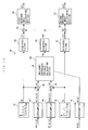
- control apparatus 1 is comprised of a target value-calculating section 29, a cooperative controller 30, an onboard model analyzer 40, and a model corrector 60 all of which are implemented by the ECU 2.
- the target value-calculating section 29 calculates a target value Pmi_cmd of the indicated mean effective pressure by searching a map shown in FIG. 26, described hereinafter, according to the engine speed NE and the accelerator pedal opening AP. It should be noted that in the present embodiment, the target value-calculating section 29 corresponds to the target value-calculating means.
- the cooperative controller 30 calculates the intake opening angle ⁇ lin and the exhaust reopening angle ⁇ rbl using two response indices RI1 and RI2 calculated by the onboard model analyzer 40, as described hereinafter, such that the indicated mean effective pressure Pmi is caused to converge to its target value Pmi_cmd. It should be noted that in the present embodiment, the cooperative controller 30 corresponds to the control input-calculating means.
- the onboard model analyzer 40 calculates the first and second response indices RI1 and RI2 using the intake opening angle ⁇ lin and the exhaust reopening angle ⁇ rbl calculated by the cooperative controller 30, the model correction parameter matrix ⁇ calculated by the model corrector 60, and the above-described controlled object model. It should be noted that in the present embodiment, the onboard model analyzer 40 corresponds to the correlation parameter-calculating means, and the model corrector means, and the first and second response indices RI1 and RI2 correspond to a plurality of correlation parameters.
- the model corrector 60 calculates the model correction parameter matrix ⁇ , as described hereinafter.
- discrete data with a symbol (k) indicates that it is data sampled or calculated at a predetermined control period ⁇ Tk (at a repetition period in synchronism with generation of each TDC signal pulse, i.e. whenever the crankshaft rotates through 180°), and the symbol k indicates a position in the sequence of sampling or calculating cycles of respective discrete data.
- the symbol k indicates that discrete data therewith is a value sampled or calculated in the current control timing
- a symbol k-1 indicates that discrete data therewith is a value sampled or calculated in the immediately preceding control timing.
- the symbol (k) and the like provided for the discrete data are omitted as deemed appropriate.
- I and J are positive integers
- f and g are positive elements which satisfy 0 ⁇ f ⁇ I and 0 ⁇ g ⁇ J, respectively.
- model corrector 60 corresponds to the model corrector means, and the model correction parameter ⁇ ij to a plurality of correction parameters.
- the model corrector 60 is comprises of a basic estimated controlled variable-calculating section 61, a nonlinear weight function matrix-calculating section 62, model correction coefficient-calculating section 63, two multipliers 64 and 66, a subtractor 65, and a model correction parameter matrix-calculating section 67.
- the basic estimated controlled variable-calculating section 61 calculates the basic estimated controlled variable Yid_nm(k) by inputting the immediately preceding value ⁇ lin(k-1) of the intake opening angle and the immediately preceding value ⁇ rbl (k-1) of the exhaust reopening angle to a controlled object model shown in FIG. 9. More specifically, similarly to the normal map search method, according to the immediately preceding values ⁇ lin(k-1) and ⁇ rbl(k-1), a plurality of values are retrieved, and the basic estimated controlled variable Yid_nm(k) is calculated interpolation of the retrieved values.
- the respective immediately preceding values ⁇ lin(k-1) and ⁇ rbl(k-1), of the intake opening angle and the exhaust reopening angle are used in the basic estimated controlled variable-calculating section 61, because the indicated mean effective pressure the present value Pmi(k) used for calculating a corrected error Eid, referred to hereinafter, is obtained as a result of inputting the immediately preceding value ⁇ lin(k-1) of the intake opening angle and the immediately preceding value ⁇ rbl(k-1) of the exhaust reopening angle to the engine 3.
- the nonlinear weight function matrix-calculating section 62 calculates a nonlinear weight function matrix W_mod ( ⁇ line (k-1), ⁇ rbl(k-1)), as referred to hereinafter.
- the nonlinear weight function matrix W_mod is a matrix with (I +1) rows and (J + 1) columns of the elements of values of nonlinear weight functions Wij ( ⁇ lin(k-1), ⁇ rbl(k-1)), and as shown in FIG. 10, the nonlinear weight functions Wij are function whose values are determined according to the intake opening angle ⁇ lin and the exhaust reopening angle ⁇ rbl.
- the nonlinear weight functions Wij are set in a manner associated respectively with a plurality of regions defined by combinations of three consecutive values of the intake opening angle ⁇ lin_i and three consecutive values of the exhaust reopening angle ⁇ rbl_j. It should be noted in the present embodiment, the nonlinear weight functions Wij correspond to the plurality of functions.
- each of the nonlinear weight functions Wij takes the maximum value of 1 with respect to the values of the intake opening angle ⁇ lin and the exhaust reopening angle ⁇ rbl in a center of each associated region, and in an area other than the center, it takes a value which changes as on inclined surfaces of a square pyramid. Outside the regions, it takes a value of 0.
- each adjacent two of a plurality of regions to which correspond the nonlinear weight functions Wij, respectively overlap each other, whereby the adjacent two of the nonlinear weight functions Wij intersect with each other, in respective portions whereby they change as on inclined surfaces of a square pyramid.
- a nonlinear weight function Wfg corresponding to a region of ⁇ lin_f-1 ⁇ ⁇ lin ⁇ ⁇ lin_f+1 and ⁇ rbl_g-1 ⁇ ⁇ rbl ⁇ ⁇ rbl_g+1 takes the maximum value of 1 when the intake opening angle ⁇ lin and the exhaust reopening angle ⁇ rbl are equal to values in respective centers of the region, i.e.
- the value of the nonlinear weight function Wfg changes as on inclined surfaces of a square pyramid. Further, it is configured such that when the two values ⁇ lin and ⁇ rbl are outside the above region, i.e.
- the nonlinear weight function Wfg takes a value of 0.
- the nonlinear weight function matrix-calculating section 62 calculates the values of the nonlinear weight functions Wij as the elements of the nonlinear weight function matrix W_ffiod, by searching the map shown in FIG. 10 according to the immediately preceding values ⁇ lin(k-1) of the intake opening angle and the immediately preceding value ⁇ rbl(k-1) of the exhaust reopening angle.
- the nonlinear weight function matrix W_mod is calculated as a matrix in which only the elements Wij corresponding to regions where the combinations of the two values ⁇ lin(k-1) and ⁇ rbl(k-1) exist have positive values (i.e. weights) not larger than 1.
- model correction coefficient-calculating section 63 calculates the model correction coefficient Yid_mod(k) using the nonlinear weight function matrix W_mod ( ⁇ line (k-1), ⁇ rbl (k-1)) calculated by the nonlinear weight function matrix-calculating section 62 as described above, and the immediately preceding value ⁇ (k-1) of the model correction parameter matrix calculated by a model correction parameter matrix-calculating section 67, referred to hereinafter, by the following equation (3).
- Yid__base is a predetermined basic value, and is set to 1 in the present embodiment. The reason for this will be described hereinafter.
- the model correction coefficient Yid_mod(k) is calculated by multiplying the nonlinear weight function matrix W mod( ⁇ line(k-1), ⁇ rbl(k-1)) by the immediately preceding value ⁇ (k-1) of the model correction parameter matrix, on an element-by-element basis, and adding the sum of the products to the basic value Yid base.
- the corrected estimated controlled variable Yid is calculated by multiplying the basic estimated controlled variable Yid_nm by the model correction coefficient Yid_mod. That is, the model correction coefficient Yid_mod corrects the basic estimated controlled variable Yid_nm, which, as a result, corrects the controlled object model in FIG. 9.
- the corrected controlled object model corresponds to one with the control inputs of two values ⁇ lin and ⁇ rbl and the controlled variable of the corrected estimated controlled variable Yid.
- the model correction coefficient Yid_mod is calculated as a value for correcting the controlled object model in FIG. 9.
- the subtractor 65 calculates an estimation error Eid by the following equation (5). More specifically, the estimation error Eid is calculated as the difference between the corrected model controlled variable Yid, which is the controlled variable of the corrected controlled object model, and the indicated mean effective pressure Pmi, which is an actual controlled variable Y.
- the multiplier 66 calculates a corrected estimation error matrix Emd by the following equation (6):
- the corrected estimation error matrix Emd is calculated by multiplying the estimation error Eid by the nonlinear weight function matrix W_mod, and hence is calculated as a matrix in which only the elements corresponding to the regions where the combination of the two values ⁇ lin(k-1) and ⁇ rbl(k-1) exists have values weighted by the elements Wij of the nonlinear weight function matrix W_mod, and the other elements are all equal to 0.
- the model correction parameter matrix ⁇ is calculated as the sum of a reaching law input matrix ⁇ rch, a non-linear input matrix ⁇ nl, and an adaptive law input matrix ⁇ adp, and the reaching law input matrix ⁇ rch is calculated by the equation (8).
- Qrch in the equation (8) is a predetermined reaching law gain
- ⁇ is a switching function as defined by the equation (11).
- R in the equation (11) represents a switching function-setting parameter set such that -1 ⁇ R ⁇ 0 holds.
- the adaptive law input matrix ⁇ adp corresponds to an integral value
- the switching function ⁇ corresponds to a value based on the difference.
- the non-linear input matrix ⁇ nl is calculated by the equation (9), and Qnl in the equation (9) represents a predetermined non-linear gain.
- the adaptive law input matrix ⁇ adp is calculated by the equation (10).
- Qadp in the equation (10) is a predetermined adaptive law gain
- ⁇ is a forgetting function set such that 0 ⁇ ⁇ ⁇ 1 holds.
- the reason for the use of the forgetting function is as follows:
- the immediately preceding value ⁇ adp(k-1) of the adaptive law input matrix is multiplied by the forgetting function, and hence when the equation (10) is expanded by a recurrence formula, the m-th preceding value ⁇ adp(k-m) is multiplied by ⁇ m ( ⁇ 0), whereby as the computation process proceeds, Yid ⁇ Pmi comes to hold, and at the time each element of the corrected estimation error matrix Emd converges to approximately 0, each element of the adaptive law input matrix ⁇ adp converge to approximately 0. As a result, it is possible to prevent the estimation error in the model correction parameter matrix ⁇ from remaining.
- the forgetting function ⁇ is used. That is, the model correction parameter matrix ⁇ is calculated while subjecting the immediately preceding value ⁇ adp(k-1) of the adaptive law input matrix as the integral value to a forgetting process by a forgetting coefficient ⁇ .
- each element of the corrected estimation error matrix Emd converges to 0 by the forgetting effect of the forgetting function ⁇ , and each element of the reaching law input matrix ⁇ rch and each element of non-linear input matrix ⁇ nl also converge to 0, whereby all the elements of the model correction parameter matrix ⁇ come to be equal to 0.
- the model corrector 60 calculates the model correction parameter matrix ⁇ with the sliding mode control algorithm as described above, and hence when Eid ⁇ 0, i.e. Yid - Pmi ⁇ 0 holds, only the elements ⁇ ij of the model correction parameter matrix ⁇ corresponding to a region where the combination of the two values ⁇ lin(k-1) and ⁇ rbl (k-1) exist are calculated as values which cause Eid to converge to 0, and the other elements ⁇ ij are calculated as 0.
- the onboard model analyzer 40 is comprised of a first periodic signal value-calculating section 41, a second periodic signal value-calculating section 42, three oversamplers 43 to 45, two adders 46 and 47, an imaginary controlled variable-calculating section 48, three high-pass filters 49 to 51, two multipliers 52 and 53, a first response index-calculating section 54, and a second response index-calculating section 55.
- discrete data with a symbol (n) indicates that it is data sampled or calculated at a predetermined control period ⁇ Tn (at a repetition period during which a total of five consecutive pulses of the CRK signal are generated, i.e. whenever the crankshaft rotates through 5°), and the symbol n indicates a position in the sequence of sampling or calculating cycles of discrete data. Further, in the following description, the symbol (n) and the like provided for the discrete data are omitted as deemed appropriate.
- the onboard model analyzer 40 calculates first and second periodic signal values S1 and S2 by the first and second periodic signal value-calculating sections 41 and 42 using the following equations (12) and (13).
- S ⁇ 1 n A ⁇ 1 ⁇ S ⁇ 1 ⁇ ⁇ n
- S ⁇ 2 n A ⁇ 2 ⁇ S ⁇ 2 ⁇ ⁇ n
- A1 represents a first predetermined amplitude gain
- S1' represents a basic value of the first periodic signal value, which is calculated by searching a map shown in FIG. 14, according to a counter value Crs.
- the counter value Crs is counted up from 0 to its maximum value Crs_max by incrementing 1 per the control period ⁇ Tn.
- the counter value Crs reaches the maximum value Crs_max, it is reset to 0.
- A2 represents a second predetermined amplitude gain
- S2' represents a basic value of the second periodic signal value and is calculated by searching the map shown in FIG. 14, according to the counter value Crs.
- the oversamplers 43 and 44 oversample an intake opening angle ⁇ lin(k) and an exhaust reopening angle ⁇ rbl(k) at the aforementioned control period ⁇ Tn, to thereby calculate respective oversampled values ⁇ lin(n) and ⁇ rbl(n) of the intake opening angle and the exhaust reopening angle.
- the intake opening angle ⁇ lin(k) and the exhaust reopening angle ⁇ rbl(k) are calculated by the cooperative controller 30 at the aforementioned control period ⁇ Tk.
- V ⁇ 1 n S ⁇ 1 n + ⁇ ⁇ 1 ⁇ in n
- V ⁇ 2 n S ⁇ 2 n + ⁇ ⁇ rb ⁇ 1 n
- the oversampler 45 oversamples the model correction parameter matrix ⁇ calculated by the model corrector 60 at the control period ⁇ Tn, thereby calculating the oversampled values ⁇ (n) of the model correction parameter matrix.
- the oversampled values ⁇ (n) are defined by the following equation (16):
- the imaginary controlled variable-calculating section 48 calculates the imaginary controlled variable Ym according to the first and second imaginary control inputs V1 and V2 and the oversampled values ⁇ (n), and as shown in FIG. 15, is comprised of a basic imaginary controlled variable-calculating section 48a, a nonlinear weight function matrix-calculating section 48b, a model correction coefficient-calculating section 48c, and a multiplier 48d.
- the imaginary controlled variable-calculating section 48a calculates the basic imaginary controlled variable Ym_nm(n) by inputting the first and second imaginary control inputs V1 and V2 to a controlled object model shown in FIG. 16.
- the controlled object model in FIG. 16 is formed by replacing the indicated mean effective pressure Pmi, the intake opening angle ⁇ lin, and the three predetermined values ⁇ rbl1 to ⁇ rbl3 of the exhaust reopening angle ⁇ rbl in the controlled object model in FIG. 6 by the basic imaginary controlled variable Ym nm, the first imaginary controlled variable V1, and three predetermined values V2_1 to V2_3 of the second imaginary controlled input V2, respectively, and hence is substantially the same as the controlled object model in FIG. 6.
- the basic imaginary controlled variable Ym_nm corresponds to the controlled variable of the controlled object model.
- nonlinear weight function matrix-calculating section 48b calculates the nonlinear weight function matrix W_mod(V1(n), V2(n)) in the same manner as the nonlinear weight function matrix-calculating section 62 described above.
- the nonlinear weight function matrix W_mod(V1(n), V2(n)) is defined by the following equation (17):
- the nonlinear weight function matrix W_mod(V1(n), V2(n)) is a matrix with (I +1) rows and (J + 1) columns of the elements of the values of the nonlinear weight functions Wij (V1(n), V2(n)), and the nonlinear weight functions Wij(V1,V2) are functions the values of which are determined according to the values of the first and second imaginary control inputs V1 and V2, as shown in FIG. 17.
- the map shown in FIG. 17 is formed by replacing the nonlinear weight functions Wij ( ⁇ lin, ⁇ rbl) and the intake opening angle ⁇ lin and the exhaust reopening angle ⁇ rbl in the aforementioned map in FIG. 10 by the nonlinear weight functions Wij(V1, V2) and the first and second imaginary control inputs V1 and V2, respectively. Therefore, the values of the nonlinear weight functions Wij(V1, V2) are calculated by searching the map in FIG. 17 according to the values of the first and second imaginary control inputs V1 and V2, as mentioned above.
- Ym_base represents a predetermined basic value, and for the same reason as described as to the aforementioned basic value Yid_base, it is set to 1.
- the , model correction coefficient Ym_mod(n) is calculated by multiplying each element of the nonlinear weight function matrix W_mod(V1(n), V2(n)) and a corresponding element of the oversampled values ⁇ (n) of the model correction parameter matrix by each other, and adding the sum of the products to the basic value Ym_base.
- the imaginary controlled variable Ym is calculated by calculating the basic imaginary controlled variable Ym_nm by the model correction coefficient Ym_mod.
- the model correction coefficient Ym mod corrects the basic imaginary controlled variable Ym_nm, which, as a result, corrects the controlled object model in FIG. 16.
- the corrected controlled object model corresponds to one with the control inputs of the first and second imaginary control inputs V1 and V2 and the controlled variables of the imaginary controlled variable Ym.
- the model correction coefficient Ym_mod is calculated as a value for correcting the controlled object model in FIG. 16.
- the imaginary controlled variable-calculating section 48 calculates the model correction coefficient Ym_mod(n) by adding the sum of products each obtained by multiplying each oversampled value ⁇ (n) of the model correction parameter matrix by a corresponding element of the nonlinear weight function matrix W_mod(V1, V2) to the basic value Ym_base, and the model correction coefficient Ym_mod(n) corrects the controlled object model in FIG. 16.
- the model correction coefficient Ym_mod(n) is calculated in the same manner as the model correction coefficient Yid mod(k) described above except for the calculation repetition period, and has the same meaning.
- the controlled object model in FIG. 16 is substantially the same as the controlled object model in FIG. 6, i.e. the controlled object model in FIG. 9.
- the model correction coefficient Ym_mod corrects the controlled object model in FIG. 16 onboard such that it matches the actual characteristics of the controlled object.
- the high-pass filter 49 in FIG. 13 calculates a filtered value Ymf of the imaginary controlled variable through a high-pass filtering process expressed by the following equation (20):
- Ymf n b ⁇ 0 ⁇ Ym n + b ⁇ 1 ⁇ Ym ⁇ n - 1 + ⁇ + bm ⁇ ⁇ Ym ⁇ n - m ⁇ + a ⁇ 1 ⁇ Ymf ⁇ n - 1 + a ⁇ 2 ⁇ Ymf ⁇ n - 2 + ⁇ + ak ⁇ ⁇ Ymf ⁇ n - k ⁇
- b0 to bm* and a0 to ak* represent predetermined filter coefficients, and m* and k* predetermined integers.
- the high-pass filters 50 and 51 calculate filtered values Sf1 and Sf2 of the first and second periodic signal values through high-pass filtering processes expressed by the following equations (21) and (22), respectively.
- the multipliers 52 and 53 calculate products Ymf ⁇ Sf1 and Ymf ⁇ Sf2 by multiplying the filtered value Ymf of the imaginary controlled variable by the respective filtered values Sf1 and Sf2 of the first and second periodic signal values.
- Kr1 and Kr2 represent response gain correction coefficients, which correct the influence of the damping characteristics of gains due to the high-pass filters 50 and 51, and makes the two values Ymf ⁇ Sf1 and Ymf ⁇ Sf2 equal in gain.
- the sum of items of the time-series data of the value Ymf ⁇ Sfl obtained by multiplying the filtered value of the imaginary controlled variable by the filtered value of the first periodic signal value, and the sum of items of the time-series data of the value Ymf ⁇ Sf2 obtained by multiplying the filtered value of the imaginary controlled variable by the filtered value of the second periodic signal value, are multiplied by the respective response gain correction coefficients Kr1 and Kr2, whereby the first and second response indices RI1 and RI2 are calculated.
- the values RI1 and RI2 are calculated as values close to a cross-correlation function between the first periodic signal value S1 and the imaginary controlled variable Ym, and a cross-correlation function between the second periodic signal value S2 and the imaginary controlled variable Ym, respectively. That is, the first response index RI1 is calculated as a value indicative of a correlation between the first periodic signal value S1 and the imaginary controlled variable Ym, and the second response index RI2 is calculated as a value indicative of a correlation between the second periodic signal value S2 and the imaginary controlled variable Ym.
- the repetition period ⁇ Tk at which the intake opening angle ⁇ 1in included in the first imaginary control input V1 is calculated is considerably longer than the repetition period ⁇ Tn at which the first response index RI1 is calculated, so that the first response index RI1 is by far larger in the degree of reflection on the imaginary controlled variable Ym, and the intake opening angle ⁇ lin becomes a steady component, which is hardly reflected on the imaginary controlled variable Ym.
- the first response index RI1 is calculated as a value indicative of a correlation between the intake opening angle ⁇ lin and the indicated mean effective pressure Pmi.
- the absolute value of the first response index RI1 becomes larger as the above correlation is higher, and becomes closer to 0 as the correlation is lower. Further, when the correlation between the intake opening angle ⁇ lin and the indicated mean effective pressure Pmi changes from one of a positive one and a negative one to the other, the sign of the first response index RI1 is inverted.
- the repetition period ⁇ Tk at which the exhaust reopening angle ⁇ rbl included in the second imaginary control input V2 is calculated is also considerably longer than the repetition period ⁇ Tn at which the first response index RI1 is calculated, so that for the same reason as described hereinabove, the second response index RI2 is calculated as a value indicative of the correlation between the exhaust reopening angle ⁇ rbl and the indicated mean effective pressure Pmi. More specifically, as the correlation between the exhaust reopening angle ⁇ rbl and the indicated mean effective pressure Pmi is higher, the absolute value of the second response index RI2 becomes larger, and as the correlation is lower, the absolute value thereof becomes closer to 0. Further, when the correlation between the exhaust reopening angle ⁇ rbl and the indicated mean effective pressure Pmi changes from one of a positive one and a negative one to the other, the sign of the second response index RI2 is inverted.
- the reason for using the respective filtered values Sf1 and Sf2 of the first and second periodic signal values, and the filtered value Ymf of the imaginary controlled variable is as follows: As described hereinbefore, the repetition period ⁇ Tk at which the intake opening angle ⁇ lin included in the first imaginary control input V1 is calculated is considerably longer than the repetition period ⁇ Tn at which the imaginary control input V1 is calculated, and the intake opening angle ⁇ lin becomes a steady component, which can cause an error in the calculation of the first response index RI1.
- the imaginary controlled variable Ym is subjected to a high-pass filtering process to use the value Ymf obtained thereby, and to make the first periodic signal value S1 in phase with the value Ymf, the first periodic signal value S1 is subjected to the same high-pass filtering process to use the value Sf1 obtained thereby.
- the imaginary controlled variable Ym is subjected to a high-pass filtering process to use the value Ymf obtained thereby, and to make the second periodic signal in phase with the value Ymf, the second periodic signal value S2 is subjected to the same high-pass filtering process to use the value Sf2 obtained thereby.
- the response gain correction coefficients Kr1 and Kr2 are used.
- the cooperative controller 30 calculates the intake opening angle ⁇ lin and the exhaust reopening angle ⁇ rbl at the same control period ⁇ Tk as the model corrector 60 operates.
- the cooperative controller 30 is comprised of a subtractor 31, an error distributor 32, two downsamplers 33 and 34, and two response-specifying controllers 35 and 36.
- the cooperative controller 30 calculates a follow-up error E using the subtractor 31 by the following equation (25):
- E k Pmi k - Pmi - ⁇ cmd k
- the downsamplers 33 and 34 downsample the first and second response indices RI1(n) and RI2(n) calculated at the above-described control period ⁇ Tn by the onboard model analyzer 40, at the control period ⁇ Tk, to thereby calculate respective downsampled values RI1(k) and RI2(k) of the first and second response indices.
- the error distributor 32 calculates first and second distributed errors Ed1 and Ed2 using the following equations (26) and (27), respectively:
- Ed ⁇ 1 k RI ⁇ 1 k
- Ed ⁇ 2 k RI ⁇ 2 k
- the first and second distributed errors Ed1 and Ed2 are calculated as values obtained by distribution of the follow-up error E according to the ratio of the absolute value RI1 of the first response index and the absolute value
- the response-specifying controller 35 calculates the intake opening angle ⁇ lin based on the first distributed error Ed1 and the first response index RI1 with a response-specifying control algorithm expressed by the following equations (28) to (32). That is, the intake opening angle ⁇ lin is calculated as a value which causes the first distributed error Ed1 to converge to 0.
- Urch1 represents a reaching law input, and is calculated using the equation (29).
- Krch1 represents a predetermined reaching law gain
- ⁇ 1 represents a switching function calculated by the equation (31).
- S represents a switching function-setting parameter set such that -1 ⁇ S ⁇ 0 holds
- Em1 represents a first follow-up error calculated by the equation (32).
- RI1_max represents the maximum value which the absolute value
- Uadp1 represents an adaptive law input, and is calculated by the equation (30).
- Kadp1 represents a predetermined adaptive law gain. It should be noted that these gains Krch1 and Kadp1 are set to such values as will make the control system stable when the absolute value
- the response-specifying controller 36 calculates the exhaust reopening angle ⁇ rbl based on the second distributed error Ed2 and the second response index RI2 with a response-specifying control algorithm expressed by the following equations (33) to (37). That is, the exhaust reopening angle ⁇ rbl is calculated as a value which causes the second distributed error Ed2 to converge to 0.
- Urch2 represents a reaching law input, and is calculated by the equation (34).
- Krch2 represents a predetermined reaching law gain
- ⁇ 2 represents a switching function calculated by the equation (36).
- Em2 represents a second follow-up error calculated by the equation (37).
- RI2_max represents the maximum value which the absolute value
- Uadp2 represents an adaptive law input, and is calculated by the equation (35).
- Kadp2 represents a predetermined adaptive law gain. It should be noted that these gains Krch2 and Kadp2 are set to such values as will make the control system stable when the absolute value
- the cooperative controller 30 calculates the intake opening angle ⁇ lin such that the intake opening angle ⁇ 1in causes the first distributed error Ed1 to converge to 0, and calculates the exhaust reopening angle ⁇ rbl such that the exhaust reopening angle ⁇ rbl causes the second distributed error Ed2 to converge to 0, with the respective response-specifying control algorithms.
- the intake opening angle ⁇ 1in and the exhaust reopening angle ⁇ rbl are calculated such that they cause the follow-up error E to converge to 0, in other words, such that they cause the indicated mean effective pressure Pmi to converge to its target value Pmi_cmd.
- the first and second follow-up errors Em1 and Em2 used in the response-specifying control algorithms are calculated by multiplying the first and second distributed errors Ed1 and Ed2 by the values RI1/RI1_max and R12/RI2-max, respectively, as shown in the equations (32) and (37), so that as the first response index RI1 becomes closer to its maximum value RI1_max, i.e. as the correlation between the intake opening angle ⁇ lin and the indicated mean effective pressure Pmi becomes higher, the increasing/decreasing rate of the intake opening angle ⁇ lin as a control input become larger. Similarly, as the second response index RI2 becomes closer to its maximum value RI2_max, i.e.
- the correlation of the indicated mean effective pressure Pmi as a controlled variable associated with the intake opening angle ⁇ lin and the exhaust reopening angle ⁇ rbl as control inputs changes according to the values of the control inputs ⁇ lin and ⁇ rbl, it is possible to determine the increasing/decreasing rates of the control inputs ⁇ lin and ⁇ rbl according to the change in the correlation, thereby making it possible to control the controlled variable Pmi such that the controlled variable Pmi converges to its target value Pmi_cmd without causing any oscillating behavior or unstable behavior. That is, it is possible to ensure high-level stability of the control.
- first and second follow-up errors Em1 and Em2 are calculated using the aforementioned equations (32) and (37), respectively, and hence when the signs of the first and second response indices RI1 and RI2 are inverted, the signs of the follow-up errors Em1 and Em2 are also inverted, whereby the increasing/decreasing directions of the intake opening angle 6lin and the exhaust reopening angle ⁇ rbl as control inputs are inverted. More specifically, the increasing/decreasing directions are each inverted from an increasing one to a decreasing one, or from the decreasing one to the increasing one.
- the first response index RI1 represents the correlation between the intake opening angle ⁇ lin and the indicated mean effective pressure Pmi, and when the correlation therebetween changes from one of the positive and negative correlations to the other, the sign of the first response index RI1 is inverted. Therefore, by inverting the increasing/decreasing direction of the intake opening angle ⁇ lin according to the change in the correlation, e.g.
- the second response index RI2 represents the correlation between the exhaust reopening angle ⁇ rbl and the indicated mean effective pressure Pmi, and when the correlation therebetween changes from one of the positive and negative correlations to the other, the sign of the second response index RI2 is inverted.
- the indicated mean effective pressure Pmi takes its local maximum value as the exhaust reopening angle ⁇ rbl is varied, even when the target value Pmi_cmd of the indicated mean effective pressure is set to a value larger than its local maximum value, it is possible to hold the indicated mean effective pressure Pmi close to its local maximum value.
- the first and second distributed errors Ed1 and Ed2 are calculated as values obtained by distribution of the follow-up error E according to the ratio of the absolute value
- one of the intake opening angle ⁇ 1in and the exhaust reopening angle ⁇ rbl, which has a higher correlation with the indicated mean effective pressure Pmi, is set a larger increasing/decreasing rate, and the other, which has a lower correlation with the indicated mean effective pressure Pmi, is set to a smaller increasing/decreasing rate.
- This process corresponds to the calculation process by the onboard model analyzer 40, and is performed at the control period ⁇ Tn.
- the counter value Crs is set to a value (Crsz + 1) obtained by adding 1 to the immediately preceding value Crsz thereof. That is, the counter value Crs is incremented by 1.
- step 2 it is determined whether or not the counter value Crs calculated in the step 1 is not smaller than the maximum value Crs_max. If the answer to this question is negative (NO), the process immediately proceeds to a step 4. On the other hand, if the answer to this question is affirmative (YES), the counter value Crs is reset to 0 in a step 3, followed by the process proceeding to the step 4.
- step 4 values of the intake opening angle ⁇ lin, the exhaust reopening angle ⁇ rbl, and the model correction parameter matrix ⁇ stored in the RAM are read in.
- these values ⁇ lin, ⁇ rbl, and ⁇ are calculated at the aforementioned control period ⁇ Tk, the step 4 is executed at the control period ⁇ Tn shorter than the control period ⁇ Tk.
- the process executed in the step 4 corresponds to calculation of the respective oversampled values ⁇ lin(n), ⁇ rbl (n) , and ⁇ (n) of the intake opening angle ⁇ lin, the exhaust reopening angle ⁇ rbl, and the model correction parameter matrix ⁇ , respectively.
- step 5 the process proceeds to a step 5, wherein the basic values S1' and S2' of the first and second periodic signal values are calculated by searching the map shown in FIG. 14, according to the counter value Crs.
- the first and second periodic signal values S1 and S2 are calculated using the aforementioned equations (12) and (13), respectively.
- the first and second imaginary control inputs V1 and V2 are calculated using the aforementioned equations (14) and (15), respectively.
- step 8 the first and second imaginary control inputs V1 and V2 calculated in the step 7 are input to the aforementioned controlled object model in FIG. 16, whereby the basic imaginary controlled variable Ym_nm is calculated. Then, the process proceeds to a step 9, wherein by searching the aforementioned map in FIG. 17 according to the first and second imaginary control inputs V1 and V2, the nonlinear weight function matrix W_mod is calculated.
- the model correction coefficient Ym_mod is calculated by using the aforementioned nonlinear weight function matrix W_mod and the model correction parameter matrix ⁇ read in the step 4, by the aforementioned equation (18), and then the process proceeds to a step 11 wherein the imaginary controlled variable Ym is calculated by the aforementioned equation (19).
- the filtered value Ymf of the imaginary controlled variable is calculated by the aforementioned equation (20), whereafter in a step 13, the filtered values Sf1 and Sf2 of the first and second periodic signal values are calculated using the aforementioned equations (21) and (22), respectively.
- step 14 wherein the two products Ymf ⁇ Sf1 and Ymf ⁇ Sf2 are calculated by multiplying the filtered value Ymf of the imaginary controlled variable, calculated in the step 12, by the respective filtered values Sf1 and Sf2 of the first and second periodic signal values, calculated in the step 13.
- the first and second response indices RI1 and RI2 are calculated using the two products Ymf ⁇ Sfl and Ymf ⁇ Sf2 calculated in the step 14, and time-series data of h Ymf ⁇ Sf1 and Ymf ⁇ Sf2 which were calculated in the immediately preceding and further preceding loops are stored in the RAM, by the aforementioned equations (23) and (24), respectively.
- each value of the Ymf ⁇ Sf1 and Ymf ⁇ Sf2 in the RAM is set to the immediately preceding value thereof which is a value preceding by one control cycle (for example, the current value Ymf (n) Sfl(n) is set to the immediately preceding value Ymf(n-1) ⁇ Sf1(n-1), and the immediately preceding value Ymf (n-1) Sf 1 (n-1) is set to the second preceding value Ymf(n-2) Sfl(n-2)), followed by terminating the present process
- the basic estimated controlled variable Yid_nm is calculated by inputting the immediately preceding values ⁇ lin(k-1) of the intake opening angle and the immediately preceding value ⁇ rbl(k-1) of the exhaust reopening angle stored in the RAM to the controlled object model described with reference to FIG. 9.
- the process proceeds to a step 21, wherein by searching the aforementioned FIG. 10 map according to the immediately preceding values ⁇ lin(k-1) of the intake opening angle and the immediately preceding value ⁇ rbl(k-1) of the exhaust reopening angle, the nonlinear weight function matrix W_mod is calculated. Then, in a step 22, the model correction coefficient Yid_mod is calculated using the nonlinear weight function matrix W_mod and the immediately preceding value ⁇ (k-1) of the model correction parameter matrix stored in the RAM by the aforementioned equation (3).
- the corrected controlled variable Yid is calculated using the basic estimated controlled variable Yid_nm calculated in the step 20 and the model correction coefficient Yid_mod calculated in the step 22 by the aforementioned equation (4). Then, in a step 24, the indicated mean effective pressure Pmi is calculated based on the in-cylinder pressure sensor 24.
- the process proceeds to a step 25, wherein the estimation error Eid is calculated using the corrected estimated controlled variable Yid and the indicated mean effective pressure Pmi calculated in the respective steps 23 and 24, by the aforementioned equation (5).
- the corrected estimation error matrix Emd is calculated using the nonlinear weight function matrix W_mod calculated in the step 21 and the estimation error Eid calculated in the step 25 by the aforementioned equation (6).
- step 26 the model correction parameter matrix ⁇ is calculated by aforementioned equations (7) to (11), followed by terminating the process.
- control process of the variable valve-actuating mechanisms which is carried out by the ECU 2 at the aforementioned control period ⁇ Tk, will be described with reference to FIG. 21.
- the control process controls the variable intake valve-actuating mechanism 4 and the variable exhaust valve-actuating mechanism 5, to thereby control the indicated mean effective pressure Pmi, and includes steps corresponding to the calculation process performed by the cooperative controller 30. This process is carried out in succession to the process for calculating the model correction parameter matrix ⁇ described above with reference to FIG. 20.
- variable mechanism failure flag F_VDNG is set to 1 when it is determined that at least one of the variable mechanisms 4 and 5 is faulty, and to 0 when it is determined that the variable mechanisms 4 and 5 are both normal. If the answer to the above question is negative (NO), i.e. if the two variable mechanisms are both normal, the process proceeds to a step 21, wherein it is determined whether or not an engine start flag F_ENGSTART is equal to 1.
- the above engine start flag F_ENGSTART is set by determining in a determination process, not shown, whether or not engine start control is being executed, i.e. the engine 3 is being cranked, based on the engine speed NE and the ON/OFF signal output from the IG ⁇ SW 26. More specifically, when the engine start control is being executed, the engine start flag F_ENGSTART is set to 1, and otherwise set to 0.
- step 31 If the answer to the question of the step 31 is affirmative (YES), i.e. if the engine start control is being executed, the process proceeds to a step 32, wherein the intake opening angle ⁇ lin is calculated by searching a map shown in FIG. 22, according to the engine coolant temperature TW.
- the intake opening angle ⁇ lin is set to a larger value as the engine coolant temperature TW is lower, and in the range where TW ⁇ TW1 holds, the intake opening angle ⁇ lin is set to a predetermined value ⁇ lin_st. This is to compensate for an increase in friction of the engine 3, which is caused when the engine coolant temperature TW is low.
- step 33 wherein the exhaust reopening angle ⁇ rbl is calculated by searching a map shown in FIG. 23, according to the engine coolant temperature TW.
- TW2 and TW3 represent predetermined values of the engine coolant temperature TW which satisfy the relationship of TW2 ⁇ TW3.
- the exhaust reopening angle ⁇ rbl is set to 0 in the range where TW ⁇ TW2 holds, and in the range where TW2 ⁇ TW ⁇ TW3 holds, the exhaust reopening angle ⁇ rbl is set to a larger value as the engine coolant temperature TW is lower, while in the range where TW3 ⁇ TW holds, the exhaust reopening angle ⁇ rbl is set to the predetermined value ⁇ rbl1. This is to reopen the exhaust valve 5a during the intake stroke so as to start the engine 3 in the compression ignition combustion for enhancement of exhaust emission, when the engine 3 is restarted in a state where the engine coolant temperature TW is high.
- a control input U_lin to the intake solenoid 4b is calculated based on the intake opening angle ⁇ lin calculated in the step 32
- a control input U_rbl to the exhaust solenoid 5b is calculated based on the exhaust reopening angle ⁇ rbl calculated in the step 33.
- step 35 it is determined whether or not the accelerator pedal opening AP is smaller than a predetermined value APREF.
- APREF it is determined whether the accelerator pedal is not stepped on, and is set to a value (e.g. 1°) so as to enable determination that the accelerator pedal is not stepped on.
- step 36 it is determined whether or not the count Tast of an after-start timer is smaller than a predetermined value Tastlmt.
- the after-start timer counts time elapsed after the termination of the engine start control, and is implemented by an up-count timer.
- step 37 wherein the intake opening angle ⁇ lin is calculated by searching a map shown in FIG. 24, according to the count Tast of the after-start timer for the catalyst warmup control and the engine coolant temperature TW.
- TW4 to TW6 represent predetermined values of the engine coolant temperature TW, which satisfy the relationship of TW4 ⁇ TW5 ⁇ TW6.
- the intake opening angle ⁇ lin is set to a larger value as the engine coolant temperature TW is lower. This is because as the engine coolant temperature TW is lower, it takes a longer time period to activate the catalyst, and hence the volume of exhaust gasses is increased to shorten the time period required for activation of the catalyst.
- the exhaust reopening angle ⁇ rbl is calculated by searching a map shown in FIG. 25, according to the count Tast of the after-start timer and the engine coolant temperature TW.
- TW7 to TW9 represent predetermined values of the engine coolant temperature TW, which satisfy the relationship of TW7 ⁇ TW8 ⁇ TW9
- Tast1 to Tast4 represent predetermined values of the count Tast of the after-start timer, which satisfy the relationship of Tast1 ⁇ Tast2 ⁇ Tast3 ⁇ Tast4.
- the exhaust reopening angle ⁇ rbl is set to 0 when the count Tast of the after-start timer is within a predetermined range (between Tast1 and Tast2, between Tast1 and Tast3, or between Tast1 and Tast4), whereas when the count Tast exceeds the predetermined range, the exhaust reopening angle ⁇ rbl is set to a larger value as the count Tast is larger. This is for the following reason: During the compression ignition combustion operation, combustion efficiency becomes higher than during the spark ignition combustion operation, and the heat energy of exhaust gases is lower.
- the engine 3 is operated in the spark ignition combustion at the start of the catalyst warmup control, and hence the valve-reopening operation for reopening the exhaust valve 5a during the intake stroke is stopped, and in accordance with the progress of the catalyst warmup control, the reopening operation is restarted during the intake stroke so as to restore the engine 3 from the spark ignition combustion operation to the compression ignition combustion operation.
- the range where the exhaust reopening angle ⁇ rbl is set to 0 is set to be larger as the engine coolant temperature TW is lower. This is because as the engine coolant temperature TW is lower, the temperature of exhaust gases becomes lower, whereby it takes a longer time period to warm up the catalyst.
- step 34 is carried out as described above, followed by terminating the present process.
- step 39 wherein the target value Pmi_cmd of the indicated mean effective pressure is calculated by searching a map shown in FIG. 26, according to the engine speed NE and the accelerator pedal opening AP.
- AP1 to AP3 represent predetermined values of the accelerator pedal opening AP, which satisfy the relationship of AP1 ⁇ AP2 ⁇ AP3.
- the target value Pmi_cmd of the indicated mean effective pressure is set to a larger value as the engine speed NE is higher or as the accelerator pedal opening AP is larger. This is because as the engine speed NE is higher or the accelerator pedal opening AP is larger, the torque demanded of the engine 3 for generation becomes larger.
- the process proceeds to a step 40, wherein the values of the first and second response indices RI1 and RI2, stored in the RAM, are read in.
- the first and second response indices RI1 and RI2 are calculated at the control period ⁇ Tn shorter than the control period ⁇ Tk of the present process, so that the process performed in the step 40 corresponds to calculation of the downsampled values RI1(k) and RI2(k) of the first and second response indices RI1 and RI2.
- a step 41 following the step 40 the intake opening angle ⁇ lin is calculated using the aforementioned equations (25), (26), and (28) to (32), and the exhaust reopening angle ⁇ rbl is calculated using the aforementioned equations (25), (27), and (33) to (37).
- in the equation (26) is limited to a predetermined value (e.g. 0.01) close to 0 by lower limit processing.
- the step 34 is executed, as described above, followed by terminating the present process.
- step 42 the control inputs U_lin and U_rbl to the intake solenoid 4b and the exhaust solenoid 5b are set to predetermined failure-time values U_lin_fs and U_rbl_fs, respectively, followed by terminating the present process.
- This causes idling or starting of the engine 3 to be appropriately performed during stoppage of the vehicle, and a low-speed traveling condition to be maintained during travel of the vehicle.
- the onboard model analyzer 40 calculates the first response index RI1 as a value indicative of the correlation between the intake opening angle ⁇ lin and the indicated mean effective pressure Pmi. More specifically, as the correlation therebetween is higher, the absolute value of the first response index RI1 becomes larger, and when the correlation therebetween changes from one of the positive and negative correlations to the other, the sign of the first response index RI1 is inverted.
- the second response index RI2 is calculated as a value indicative of the correlation between the exhaust reopening angle ⁇ rbl and the indicated mean effective pressure Pmi. More specifically, as the correlation therebetween is higher, the absolute value of the second response index RI2 becomes larger, and when the correlation therebetween changes from one of the positive and negative correlations to the other, the sign of the second response index RI2 is inverted.
- the cooperative controller 30 calculates the intake opening angle ⁇ 1in and the exhaust reopening angle ⁇ rbl with the response-specifying control algorithms such that the indicated mean effective pressure Pmi is caused to converge to its target value Pmi_cmd.
- the first and second follow-up errors Em1 and Em2 used in the response-specifying control algorithms are calculated by multiplying the first and second distributed errors Ed1 and Ed2 by the values RI1/RI1_max and RI2/RI2_max, respectively, so that as the first response index RI1 becomes closer to its maximum value RI1_max, i.e.
- the correlation of the indicated mean effective pressure Pmi as a controlled variable to the intake opening angle ⁇ lin and the exhaust reopening angle ⁇ rbl as control inputs changes according to the values of the control inputs ⁇ lin and ⁇ rbl, it is possible to determine the increasing/decreasing rates of the control inputs ⁇ lin and ⁇ rbl according to the changes in the correlation, thereby making it possible to control the controlled variable Pmi such that the controlled variable Pmi converges to its target value Pmi_cmd without causing any oscillating behavior or unstable behavior. That is, it is possible to ensure high-level stability of control.
- first and second follow-up errors Em1 and Em2 are calculated using the aforementioned equations (32) and (37), respectively, and hence when the signs of the first and second response indices RI1 and RI2 are inverted, the signs of the follow-up errors Em1 and Em2 are also inverted, whereby the increasing/decreasing directions of the intake opening angle ⁇ lin and the exhaust reopening angle ⁇ rbl as control inputs are inverted. More specifically, each increasing/decreasing direction is inverted from the increasing direction to the decreasing direction, or from the decreasing direction to the increasing direction.
- the indicated mean effective pressure Pmi takes its local maximum value as the exhaust reopening angle ⁇ rbl is varied, as in the present embodiment, even when the target value Pmi_cmd of the indicated mean effective pressure is set to a value larger than its local maximum value, it is possible to hold the indicated mean effective pressure Pmi close to its local maximum value. That is, even when the controlled object having extremal characteristics is controlled, it is possible to ensure both high-level stability and accuracy of control.
- the first and second distributed errors Ed1 and Ed2 are calculated as values obtained by distribution of the follow-up error E according to the ratio of the absolute value
- one of the intake opening angle ⁇ lin and the exhaust reopening angle ⁇ rbl, which has a higher correlation with the indicated mean effective pressure Pmi, is set to be larger in the increasing/decreasing rate, and the other, which has a lower correlation with the indicated mean effective pressure Pmi, is set to be smaller in the increasing/decreasing rate.
- the model corrector 60 calculates the model correction parameter matrix ⁇ , onboard, such that the controlled object model in FIG. 9 matches actual characteristics of the controlled object.
- the imaginary controlled variable-calculating section 48 of the onboard model analyzer 40 corrects the controlled object model in FIG. 16 which is substantially the same as the controlled object model in FIG. 9, using the model correction parameter matrix ⁇ calculated as described above, onboard, such that it matches the actual characteristics of the controlled object, and hence even when the modeling error occurs due to variation between individual products of the engine 3 and the aging of the same, it is possible to quickly accommodate the modeling error, and increase the accuracy of calculation of the first and second response indices RI1 and RI2.
- elements ⁇ ij of the model correction parameter matrix ⁇ are set in a manner associated with a plurality of regions defined by combinations of three consecutive values of the intake opening angle ⁇ lin_i and three consecutive values of the exhaust reopening angle ⁇ rbl_j, and only elements ⁇ ij associated with regions where the combination of two values ⁇ lin (k-1) and ⁇ rbl(k-1) exists are calculated with a sliding mode control algorithm shown in the equations (7) to (11), as described above, such that the estimation error Eid converges to 0 (more specifically such that the corrected estimated controlled variable Yid converges to the indicated mean effective pressure Pmi), and the other elements ⁇ ij are calculated as 0.
- model correction parameter matrix ⁇ is calculated with a sliding mode control algorithm, and hence even in the case of the controlled object the controlled object model of which cannot be expressed using a recurrence formula, as in the case of the engine 3, it is possible to calculate the model correction parameter matrix ⁇ as a value that does not cause an unstable behavior, such as an oscillating behavior or overshooting. Further, using the model correction parameter matrix ⁇ thus calculated, it is possible to control the engine 3 while correcting the controlled object model onboard. As a result, it is possible to prevent the transient response of the control system from becoming oscillatory or unstable, and improve the control accuracy during a transition period.
- the controlled object mode is corrected by the model correction coefficient Ym_mod, and the model correction coefficient Ym_mod is calculated by adding the basic value Ym_base to the sum of the products of corresponding elements of the model correction parameter matrix ⁇ and the nonlinear weight function matrix W_mod.
- the nonlinear weight functions Wij as the elements of the nonlinear weight function matrix W_mod have characteristics that with respect to the first and second imaginary control inputs V1 and V2 in a plurality of regions, they take each the maximum value of 1, in the center or its vicinity of each of the associated regions, and take a value of 0 outside the regions, and are set such that each two of the nonlinear weight functions Wij in respective overlapping portions of the regions intersect with each other, in portions where they change in a planar fashion. Therefore, when the model correction coefficient Ym_mod corrects the controlled object model, it can correct the same continuously over a plurality of regions of the first and second imaginary control inputs V1 and V2, whereby the corrected controlled object model no longer has discontinued points. This makes it possible to prevent the transient response of the control system from becoming temporarily unstable due to the discontinued points of the controlled object model, and further improve the control accuracy during the transient time.
- the immediately preceding value ⁇ adp(k-1) of the adaptive law input matrix is multiplied by the forgetting coefficient ⁇ in the equation (10) for calculating the adaptive law input matrix ⁇ adp, and hence at the time point where each element of the corrected estimation error matrix Emd converges to approximately 0, each element of the adaptive law input matrix ⁇ adp converges to approximately 0.
- the model correction parameter matrix ⁇ can be calculated as appropriate values, and the stability of the control system can be improved.
- the predetermined first algorithm is not limited to this, but any suitable algorithm may be used insofar as it is capable of causing the controlled variable of the controlled object to converge to the target value, and determining the increasing/decreasing rate and/or the increasing/decreasing direction of the control input according to the correlation parameters.
- a general feedback control algorithm such as a PID control algorithm, may be used as the predetermined first control algorithm.
- the predetermined second control algorithm shown in the equations (7) to (11) is used for the predetermined second control algorithm
- the predetermined second control algorithm according to the present embodiment is not limited to this, but any suitable algorithm may be used insofar as it is capable of calculating the correction parameter such that the controlled variable of the controlled object model matches the controlled variable of the controlled object.
- a general feedback control algorithm such as a PID control algorithm
- a response-specifying control algorithm such as a back-stepping control algorithm
- the nonlinear weight functions Wij are used, by way of example, the values of which change on inclined surfaces of square pyramids associated with a plurality of regions divided by combinations of the intake opening angle ⁇ lin and the exhaust reopening angle ⁇ rbl
- the plurality of functions in the present invention are not limited to this, but functions having characteristics that they take the maximum value in the center or in its vicinity of each of a plurality of regions, and change in a planar fashion or in a curviplanar fashion, and ones of the functions corresponding to two overlapping regions intersect with each other, in portions where they change in a planar fashion or in a curviplanar fashion.
- functions which are configured such that they continuously change on four side surfaces of a square pyramid with respect to the two values ⁇ lin and ⁇ rbl or functions which are configured such that they continuously change on four inclined surfaces of a hexahedron which divergently extend from the four inclined surfaces of the square pyramid.
- functions the values of which change on curved surfaces with respect to the two values ⁇ lin and ⁇ rbl may be used.
- the plurality of functions the maximum value of which is set to 1 are used, by way of example, this is not limitative, but there by may be used ones the maximum value of which is set to a value larger than 1 or is set to a value smaller than 1.
- the map for calculating the nonlinear weight functions Wij there is used, by way of example, one shown in FIG. 10 in which the plurality of regions are defined by equally dividing the range within which are variable the intake opening angle ⁇ lin and the exhaust reopening angle ⁇ rbl, this is not limitative, but as the map for calculating nonlinear weight functions Wij, there may be used one in which a plurality of regions are defined by unequally dividing the range within which are variable the intake opening angle ⁇ lin and the exhaust reopening angle ⁇ rbl. In this case, it is only required to use a map in which a plurality of regions are equal in area, and which is configured such that a total of the values of two functions in overlapping portions of two adjacent ones of the nonlinear weight functions Wij is equal to 1.
- the first and second response indices RI1 and RI2 are used as the correlation parameters, by way of example, the correlation parameters are not limited to these, but they are only required to represent a control input and a controlled variable in the controlled object model.
- the response indices RI1 and RI2 as the correlation parameters may be calculated by multiplying a filtered value Ymf of the controlled variable by filtered values Sf1 and Sf2 of two periodic signal values to thereby calculate time-series data of (h + 1) products Ymf ⁇ Sf1 and Ymf ⁇ Sf2, and multiplying the moving average value of the time-series data by the response gain correction coefficients Kr1 and Kr2.
- control apparatus 1 is applied to the engine 3 as the controlled object, by way of example, this is not limitative, but the control apparatus according to the present invention may be applied to various industrial apparatuses, particularly to ones having extremal characteristics, and even to ones the controlled object model of which cannot be expressed by recurrence formulas, i.e. a discrete-time system model.
- the controlled object models in FIGS. 6, 9, and 16 are used as the controlled object model, by way of example, this is not limitative, but the control apparatus according to the present invention can employ various controlled object models which cannot be expressed using recurrence formulas.
- control apparatus 1A according to a second embodiment of the present invention will be described with reference to FIGS. 27 to 36.
- the control apparatus 1A is distinguished from the control system according to the first embodiment only in the configuration of the method of controlling the indicated mean effective pressure Pmi, and hereinafter, the description will be given of the different points.
- the control apparatus 1A controls the indicated mean effective pressure Pmi only by the exhaust reopening angle ⁇ rbl in a state where the intake opening angle ⁇ lin is held constant, e.g. when the engine 3 is in a steady operating condition.
- the control apparatus 1A uses a controlled object model shown in FIG. 27, in place of the controlled object model according to the first embodiment shown in FIG. 6.
- the controlled object model is configured such that the indicated mean effective pressure Pmi takes the local maximum value with respect to an increase/decrease of the exhaust reopening angle ⁇ rbl.
- the reason for the configuration is the same as described in the explanation given with reference to FIG. 6.
- control apparatus 1A is comprised of a target value-calculating section 129, a controller 130, an onboard model analyzer 140, and a model corrector 160 all of which are implemented by the ECU 2.
- the target value-calculating section 129 calculates a target value Pmi_cmd of the indicated mean effective pressure by searching the aforementioned map shown in FIG. 26 according to the engine speed NE and the accelerator pedal opening AP. It should be noted that in the present embodiment, the target value-calculating section 129 corresponds to the target value-calculating means.
- controller 130 calculates the exhaust reopening angle ⁇ rbl using the response index RI calculated by the onboard model analyzer 140, as described hereinafter, such that the indicated mean effective pressure Pmi is caused to converge to its target value Pmi_cmd. It should be noted that in the present embodiment, the controller 130 corresponds to the control input-calculating means.
- the onboard model analyzer 140 calculates the response index RI using the exhaust reopening angle ⁇ rbl calculated by the controller 130, a model correction parameter vector ⁇ ' calculated by the model corrector 160, and the above-described controlled object model. It should be noted that in the present embodiment, the onboard model analyzer 140 corresponds to the correlation parameter-calculating means, and the model corrector means, and the response index RI corresponds to a correlation parameter.
- model corrector 160 calculates the model correction parameter vector ⁇ ', as described hereinafter.
- model corrector 160 corresponds to the model corrector means, and the model correction parameter ⁇ j to the plurality of correction parameter.
- the model corrector 160 is comprises of a basic estimated controlled variable-calculating section 161, a nonlinear weight function vector-calculating section 162, model correction coefficient-calculating section 163, two multipliers 164 and 166, a subtractor 165, and a model correction parameter vector-calculating section 167.
- the basic estimated controlled variable-calculating section 161 calculates the basic estimated controlled variable Yid_nm' (k) by inputting the immediately preceding value ⁇ rbl(k-1) of the exhaust reopening angle to a controlled object model shown in FIG. 30.
- the controlled object model shown in FIG. 30 is formed by replacing Pmi set to the vertical axis by Yid_nm', in the above-described controlled object model shown in FIG. 27. In short, it is substantially the same as that in FIG. 27.
- the immediately preceding value ⁇ rbl(k-1) of the exhaust reopening angle is used in the basic estimated controlled variable-calculating section 161 for the same reason as described concerning the basic estimated controlled variable-calculating section 61.
- the basic estimated controlled variable Yid_nm' corresponds to the controlled variable of the controlled object model.
- nonlinear weight function vector-calculating section 162 calculates a nonlinear weight function vector W_mod' ( ⁇ rbl(k-1)), as referred to hereinafter.
- the nonlinear weight function Wj is a function whose value is determined according to the exhaust reopening angle ⁇ rbl.
- the nonlinear weight function Wj corresponds to the plurality of functions.
- each of the nonlinear weight function Wj takes the maximum value of 1 with respect to the value of the exhaust reopening angle ⁇ rbl in a center of each associated region, and in an area other than the center, it takes a value which changes on inclined sides of an isosceles triangle, while taking a value of 0 outside the regions.
- each adjacent two of the regions overlap each other, whereby each adjacent two of the nonlinear weight functions Wj intersect with each other, in a portion whereby they change on the inclined sides of an isosceles triangle.
- the nonlinear weight function Wg takes a value of 0. Further, inclined surfaces of an isosceles triangle on which the value of the nonlinear weight function Wg changes intersects with inclined surfaces of isosceles triangles on which change the respective values of the nonlinear weight functions Wg-1 and Wg+1 corresponding to regions adjacent to the region of the nonlinear weight function Wg, in portions of these regions where they overlap each other.
- the nonlinear weight function vector-calculating section 162 calculates the values of the nonlinear weight functions Wj as the elements of the nonlinear weight function vector W_mod' ( ⁇ rbl(k-1), by searching the map shown in FIG. 31 according to the immediately preceding value ⁇ rbl(k-1) of the exhaust reopening angle, whereby the nonlinear weight function vector W_mod' (8rbl(k-1)) is calculated.
- Yid_base' is a predetermined basic value, and is set to 1 in the present embodiment. The reason for this will be described hereinafter.
- the model correction coefficient Yid_mod'(k) is calculated by adding the inner product of the nonlinear weight function vector W_mod'(0rbl(k-l)) and the immediately preceding value ⁇ ' (k-1) of the model correction parameter vector to the basic value Yid_base'.
- the multiplier 164 calculates a corrected estimated controlled variable Yid' by the following equation (41).
- the corrected estimated controlled variable Yid' is calculated by multiplying the basic estimated controlled variable Yid_nm' by the model correction coefficient Yid_mod', and hence, this corresponds to correction of the controlled object model in FIG. 30 by the model correction coefficient Yid_mod'.
- Yid ⁇ ( k ) Yid - ⁇ nm ⁇ k ⁇ Yid - ⁇ mod ⁇ k
- the subtractor 165 calculates an estimation error Eid' by the following equation (42). More specifically, the estimation error Eid' is calculated as the difference between the corrected model controlled variable Yid', which is the controlled variable of the corrected controlled object model, and the indicated mean effective pressure Pmi, which is an actual controlled variable.
- the multiplier 166 calculates a corrected estimation error vector Emd' by the following equation (43). More specifically, the corrected estimation error vector Emd' is calculated by correcting the estimation error Eid' by the nonlinear weight function vector W_mod' .
- the model correction parameter vector ⁇ ' is calculated as the sum of a reaching law input ⁇ rch', a non-linear input ⁇ nl', and an adaptive law input vector ⁇ adp', and the reaching law input vector ⁇ rch' is calculated by the equation (8).
- Qrch' in the equation (45) is a predetermined reaching law gain
- ⁇ ' is a switching function as defined by the equation (48).
- R' in the equation (48) represents a switching function-setting parameter set such that -1 ⁇ R' ⁇ 0 holds.
- the adaptive law input vector ⁇ adp' corresponds to an integral value
- the switching function ⁇ ' corresponds to a value based on the difference.
- the non-linear input vector ⁇ nl' is calculated by the equation (46), and Qnl' in the equation (46) represents a predetermined non-linear gain.
- the adaptive law input vector ⁇ adp' is calculated by the equation (47).
- Qadp' in the equation (47) is a predetermined adaptive law gain, and ⁇ ' is a forgetting function set such that 0 ⁇ ⁇ ' ⁇ 1 holds.
- the reason for the use of the forgetting function is the same as described concerning the forgetting function ⁇ of the first embodiment.
- the model correction parameter vector ⁇ ' is calculated while subjecting the immediately preceding value ⁇ adp' (k-1) of the adaptive law input vector to a forgetting process by a forgetting coefficient ⁇ '.
- the model corrector 160 calculates the model correction parameter vector ⁇ ' with the sliding mode control algorithm as described above, when Eid' ⁇ 0, i.e. Yid' - Pmi ⁇ 0 holds, only the element ⁇ j of the model correction parameter vector ⁇ ' corresponding to a region where the value ⁇ rbl(k-1) exists is calculated as a value which causes Eid' to converge to 0, and the other elements ⁇ j are calculated as 0. Further, as described hereinabove, the model correction coefficient Yid_mod' is calculated by adding the basic value Yid_base' to the inner product of the immediately preceding value ⁇ ' (k-1) of the model correction parameter vector and the nonlinear weight function vector W_mod', calculated as above.
- the onboard model analyzer 140 is comprised of a second periodic signal value-calculating section 142, two oversamplers 141 and 143, an adder 144, an imaginary controlled variable-calculating section 145, two high-pass filters 146 and 147, a multiplier 148, a response index-calculating section 149.
- the second periodic signal value-calculating section 142 calculates the second periodic signal value S2(n) by the same method as that of the second periodic signal value-calculating section 42 of the first embodiment.
- the oversampler 142 calculates the oversampled values ⁇ rbl(n) of the exhaust reopening angle, by oversampling the exhaust reopening angle ⁇ rbl(k) at the aforementioned control period ⁇ Tn.
- the adder 144 calculates the second imaginary control input V2(n) by adding together the second periodic signal value S2(n) and the oversampled value ⁇ rbl (n) of the exhaust reopening angle.
- the oversampler 143 oversamples the model correction parameter vector ⁇ ' calculated by the model corrector 160 at the control period ⁇ Tn, thereby calculating the oversampled values ⁇ ' (n) of the model correction parameter vector.
- the imaginary controlled variable-calculating section 145 calculates the imaginary controlled variable Ym' according to the oversampled values ⁇ ' (n) and the second imaginary control input V2, and as shown in FIG. 34, is comprised of a basic imaginary controlled variable-calculating section 145a, a nonlinear weight function vector-calculating section 145b, a model correction coefficient-calculating section 145c and a multiplier 145d.
- the imaginary controlled variable-calculating section 145a calculates the basic imaginary controlled variable Ym_nm' (n) by inputting the second imaginary control input V2 to the controlled object model shown in FIG. 35.
- the controlled object model in FIG. 35 is formed by replacing Pmi set to the vertical axis by Ym_nm', and ⁇ rbl set to the horizontal axis by V2 in the controlled object model in FIG. 27, and hence is substantially the same as the controlled object model in FIG. 27.
- the basic imaginary controlled variable Ym_nm' corresponds to the controlled variable of the controlled object model.
- the nonlinear weight function vector-calculating section 145b calculates the nonlinear weight function vector W_mod' (V2(n)) in the same manner as the nonlinear weight function vector-calculating section 162. More specifically, the nonlinear weight function vector W mod'(V2(n)) is calculated by searching a map, not shown, which is prepared by replacing ⁇ rbl in FIG. 31 set to the horizontal axis by V2, according to the second imaginary control input V2.
- the model correction coefficient-calculating section 145c calculates the model correction coefficient Ym_mod'(n) by the following equation (51).
- Ym_base' represents a predetermined basic value, and is set to 1 for the same reason as described as to the aforementioned basic value Yid_base'.
- the multiplier 145d calculates the imaginary controlled variable Ym' by the following equation (52).
- the imaginary controlled variable Ym' is calculated by multiplying the basic imaginary controlled variable Ym_nm' by the model correction coefficient Ym_mod', and hence this is equivalent to correction of the controlled object model in FIG. 35 by the model correction coefficient Ym_mod'.
- Ym ⁇ ( n ) Ym - ⁇ nm ⁇ n ⁇ Ym - ⁇ mod ⁇ n
- the imaginary controlled variable-calculating section 145 calculates the model correction coefficient Ym_mod'(n) by a dding the inner product of the oversampled values ⁇ ' (n) of the model correction parameter vector and the nonlinear weight function vector W_mod'(V2(n)) to the basic value Ym_base to the basic value Ym_base, and the model correction coefficient Ym_mod'(n) corrects the controlled object model in FIG. 35.
- the model correction coefficient Ym_mod' (n) is calculated in the same manner as the model correction coefficient Yid_mod'(k) described above, at other than the calculation repetition period, and has the same meaning.
- the controlled object model in FIG. 35 is substantially the same as the controlled object model in FIG. 27, i.e. the controlled object model in FIG. 30.
- the model correction coefficient Ym_mod' corrects the controlled object model in FIG. 35 onboard such that it matches the actual characteristics of the controlled object.
- the high-pass filter 46 calculates a filtered value Ymf' of the imaginary controlled variable through a high-pass filtering process expressed by the following equation (53):
- Ymf ⁇ n b ⁇ 0 ⁇ Ym ⁇ n + b ⁇ 1 ⁇ Ym ⁇ ⁇ n - 1 + ⁇ + bm ⁇ ⁇ Ym ⁇ ⁇ n - m ⁇ + a ⁇ 1 ⁇ Ymf ⁇ ⁇ n - 1 + a ⁇ 2 ⁇ Ymf ⁇ ⁇ n - 2 + ⁇ + ak ⁇ ⁇ Ymf ⁇ ⁇ n - k ⁇
- the high-pass filter 147 calculate filtered value Sf2 of the second periodic signal values through high-pass filtering processes expressed by the following equation (54):
- Sf ⁇ 2 n b ⁇ 0 ⁇ S ⁇ 2 n + b ⁇ 1 ⁇ S ⁇ 2 ⁇ n - 1 + ⁇ + bm ⁇ ⁇ S ⁇ 2 ⁇ n - m ⁇ + a ⁇ 1 ⁇ Sf ⁇ 2 ⁇ n - 1 + a ⁇ 2 ⁇ Sf ⁇ 2 ⁇ n - 2 + ⁇ + ak ⁇ ⁇ Sf ⁇ 2 ⁇ n - k ⁇
- the multiplier 148 calculate a multiplied value (product) Ymf' ⁇ Sf2 by multiplying the filtered value Ymf' of the imaginary controlled variable by the filtered value Sf2 of the second periodic signal value.
- the onboard model analyzer 140 calculates the response index Ri by the method described above.
- the controller 130 calculates the exhaust reopening angle ⁇ rbl at the aforementioned control period ⁇ Tk.
- the controller 130 is comprised of a subtractor 131, a downsampler 132, and a response-specifying controller 133.
- the controller 130 calculates a follow-up error E using the subtractor 131 by the following equation (56):
- E k Pmi k - Pmi - ⁇ cmd k
- the downsampler 132 downsamples the response index RI(n) calculated at the above-described control period ⁇ Tn by the onboard model analyzer 140, at the control period ⁇ Tk, to thereby calculate respective downsampled value RI(k) of the response index.
- Urch represents a reaching law input, and is calculated using the equation (58).
- Krch represents a predetermined reaching law gain
- ⁇ represents a switching function calculated by the equation (60).
- S' represents a switching function-setting parameter set such that -1 ⁇ S' ⁇ 0 holds
- Em represents a corrected follow-up error calculated by the equation (61).
- RI_max represents the maximum value which the absolute value
- Uadp represents an adaptive law input, and is calculated by the equation (59).
- Kadp represents a predetermined adaptive law gain. It should be noted that these gains Krch and Kadp are set to such values as will make the control system stable when the absolute value
- the controller 130 calculates the exhaust reopening angle ⁇ rbl such that the exhaust reopening angle ⁇ rbl causes the follow-up error E to converge to 0. In other words, such that they cause the indicated mean effective pressure Pmi to converge to its target value Pmi_cmd.
- control results of a simulation of control of the indicated mean effective pressure by the control apparatus 1A according to the second embodiment with reference to FIGS. 37 to 40.
- FIGS. 37 and 38 show an example of control results obtained when the model correction parameter vector ⁇ ' in the model corrector 160 is configured to be formed by three elements ⁇ 1 to ⁇ 3.
- FIG. 37 shows control results obtained when the controlled object models in FIGS. 27, 30, and 35 are configured such that there is no modeling error with respect to the actual characteristics of the controlled object.
- FIG. 38 shows control results obtained when the controlled object models are configured such that there is a modeling error with respect to the same.
- Pmi_max represents the maximum value of the indicated mean effective pressure Pmi which the engine 3 can produce.
- FIGS. 39 and 40 show control results obtained when the imaginary controlled variable-calculating section 145 calculates the imaginary controlled variable Ym' by inputting the second imaginary control input V2 to the controlled object model in FIG. 35, by omitting the model corrector 160 (i.e. without using the model correction parameter vector ⁇ ').
- FIG. 39 shows an example of control results obtained by configuring the controlled object model such that there is no modeling error
- FIG. 40 shows an example of control results obtained by configuring the controlled object model such that there is a modeling error.
- the target value Pmi_cmd is set to be fairly smaller than the maximum value Pmi_max at a time point t43, it takes time before the indicated mean effective pressure Pmi converges to the target value Pmi_cmd.
- the model corrector 160 is not used, if there occurs a modeling error, the control accuracy is degraded.
- the controlled object model is corrected so as to eliminate the modeling error, so that the indicated mean effective pressure Pmi is controlled to converge to its target value Pmi_cmd. Further, when the target value Pmi_cmd is set to a value larger than the maximum value Pmi_max at a time point t22, the indicated mean effective pressure Pmi is properly held at the maximum value Pmi_max.
- the model corrector 160 is used, even when there occurs a modeling error, it is possible to secure an excellent control accuracy.
- the onboard model analyzer 140 calculates the first response index RI as a value indicative of the correlation between the exhaust reopening angle ⁇ rbl and the indicated mean effective pressure Pmi.
- the controller 130 calculates the exhaust reopening angle ⁇ rbl with the response-specifying control algorithm such that the indicated mean effective pressure Pmi is caused to converge to its target value Pmi_cmd.
- the corrected estimation error Em used in the response-specifying control algorithms is calculated by multiplying the follow-up error E by the values RI/RI max, so that as the response index RI becomes closer to its maximum value RI_max, i.e. as the correlation between the exhaust reopening angle ⁇ rbl and the indicated mean effective pressure Pmi becomes higher, the increasing/decreasing rate of the exhaust reopening angle ⁇ rbl as a control input become larger.
- the sensitivity i.e.
- the correlation of the indicated mean effective pressure Pmi as a controlled variable associated with the exhaust reopening angle ⁇ rbl as control inputs changes according to the value of the control input ⁇ rbl, it is possible to determine the increasing/ decreasing rate of the control input ⁇ rbl according to the change in the correlation, thereby making it possible to control the controlled variable Pmi such that the controlled variable Pmi converges to its target value Pmi_cmd without causing any oscillating behavior or unstable behavior. That is, it is possible to ensure high-level stability of the control.
- the second follow-up error Em is calculated using the aforementioned equation (61), and hence when the sign of the response indices RI is inverted, the sign of the corrected follow-up error Em is also inverted, whereby the increasing/decreasing direction of the exhaust reopening angle ⁇ rbl as the control input is inverted. More specifically, the increasing/decreasing direction is inverted from an increasing one to a decreasing one, or from the decreasing one to the increasing one.
- the indicated mean effective pressure Pmi shows its local maximum value as the exhaust reopening angle ⁇ rbl is varied, even when the target value Pmi cmd of the indicated mean effective pressure is set to a value larger than its local maximum value, it is possible to hold the indicated mean effective pressure Pmi close to its local maximum value.
- the model corrector 160 calculates the model correction parameter vector ⁇ ', onboard, such that the controlled object model in FIG. 30 matches actual characteristics of the controlled object.
- the imaginary controlled variable-calculating section 148 of the onboard model analyzer 140 corrects the controlled object model in FIG. 35 which is substantially the same as the controlled object model in FIG. 30, using the model correction parameter vector ⁇ ' calculated as described above, onboard such that it matches the actual characteristics of the controlled object. Therefore, even when a modeling error occurs due to the variations between individual products of the engine 3 and the aging of the engine 3, it is possible to quickly accommodate the modeling error, and increase the accuracy of calculation of the response index RI.
- elements ⁇ j of the model correction parameter vector ⁇ ' are set in a manner associated with a plurality of regions defined by three consecutive values of the exhaust reopening angle ⁇ rbl_j, and only elements ⁇ j associated with regions where the value ⁇ rbl(k-1) exists are calculated with a sliding mode control algorithm shown in the equations (44) to (48), as described above, such that the estimation error Eid' converges to 0 (more specifically such that the corrected estimated controlled variable Yid' converges to the indicated mean effective pressure Pmi), and the other elements ⁇ j are calculated as 0.
- model correction parameter vector ⁇ ' is calculated with a sliding mode control algorithm, and hence even in the case of the controlled object the controlled object model of which cannot be expressed using the recurrence formula, as in the case of the engine 3, it is possible to calculate the model correction parameter vector ⁇ ' as a value that does not cause an unstable behavior, such as an oscillating behavior or overshooting. Further, using the model correction parameter vector ⁇ ' thus calculated, it is possible to control the engine 3 while correcting the controlled object model. As a result, it is possible to prevent the transient response of the control system from becoming oscillatory or unstable, and improve the control accuracy during a transition period.
- the controlled object mode is corrected by the model correction coefficient Ym_mod', and the model correction coefficient Ym_mod' is calculated by adding the basic value Ym_base' to the sum of products of each element of the model correction parameter vector ⁇ ' and a corresponding element of the nonlinear weight function vector W_mod'.
- the nonlinear weight functions Wj as the elements of the nonlinear weight function vector W_mod' have characteristics that with respect to the second imaginary control input V2 in a plurality of regions, they take the maximum value of 1 in the center or its vicinity of each of the regions, and change on the inclined sides of an isosceles triangle, and they take 0 outside the regions.
- each two of the nonlinear weight functions Wij associated with respective overlapping regions intersect with each other, in portions where they change as on the inclined sides of an isosceles triangle. Therefore, when the model correction coefficient Ym_mod' corrects the controlled object model, it can correct the same continuously over a plurality of regions of the second imaginary control input V2, whereby the corrected controlled object model no longer has discontinued points. This makes it possible to prevent the transient response of the control system from becoming temporarily unstable due to the discontinued points of the controlled object model, and further improve the control accuracy during the transient time.
- the immediately preceding value ⁇ adp'(k-1) of the adaptive law input vector is multiplied by the forgetting coefficient ⁇ ', in the equation (47) for calculating the adaptive law input vector ⁇ adp', and hence when at the time point where each element of the corrected estimation error vector Emd' converges to approximately 0, each element of the adaptive law input vector ⁇ ' adp comes to converge to approximately 0.
- the model correction parameter vector ⁇ ' can be calculated as an appropriate value, and the stability of the control system can be improved.
- the nonlinear weight functions Wj that change on the inclined sides of an isosceles triangle in a plurality of regions divided by values of the exhaust reopening angle ⁇ rbl are used as the plurality of functions according to the present invention by which the correction parameters are multiplied
- the plurality of functions according to the present invention are not limited to them, but any suitable functions may be used insofar as they have characteristics that they each take the maximum value in respective centers or their vicinities of associated regions and change linearly or curvilinearly, and are configured such that each two functions corresponding to respective two overlapping regions intersect with each other at portions where they change linearly or curvilinearly.
- the sum of the values of two functions in overlapping portions of the respective associated regions takes a value equal to the maximum value, or that with respect to any value of the exhaust reopening angle ⁇ rbl, the sum of two functions corresponding thereto takes a value equal to the maximum value.
- the nonlinear weight functions Wj in the second embodiment may be replaced by functions that have characteristics that change as on a polygon, such as a trapezoid or a pentagon, except the bottom surface thereof, and as to two adjacent elements thereof, respective portions of the elements that change linearly intersect with each other.
- the nonlinear weight functions Wj according to the second embodiment may be replaced by nonlinear weight functions Wj shown in FIG. 41. As shown in FIG.
- the nonlinear weight functions Wj are of a curve type which uses a sigmoid function, and are configured such that two adjacent functions intersect with each other, and the sum of the values of two functions corresponding to the exhaust reopening angle ⁇ rbl is equal to 1 at the intersecting portions.
- the use of such a nonlinear weight functions Wj can also provide the same advantageous effects as provided by the nonlinear weight functions Wj in the second embodiment.
- the map for calculating the nonlinear weight functions Wj the one shown in FIG. 31 in which a plurality of regions are defined by equally dividing a range within which the exhaust reopening angle ⁇ rbl is variable
- the map is only required to be configured such that the regions are equal in area, and the sum of two values of intersecting portions of two adjacent nonlinear weight functions Wj is equal to 1.
- the indicated mean effective pressure Pmi is controlled only by the exhaust reopening angle ⁇ rbl, with the intake opening angle ⁇ lin held constant, by way of example, it is to be understood that the conditions for applying the method of controlling the control apparatus 1A according to the second embodiment are not limited to the above.
- the intake opening angle ⁇ lin may be calculated by searching a map according to the operating conditions of the engine, and then the exhaust reopening angle ⁇ rbl may be controlled by the same method as in the second embodiment, to thereby control the indicated mean effective pressure Pmi such that it is caused to converge to its target value Pmi_cmd.
- the control method according to the second embodiment may be used when the engine is in a steady operating condition with the intake opening angle ⁇ lin being held constant, and when the engine has changed from the steady operating condition into a condition other than the same, the method of controlling the indicated mean effective pressure Pmi may be switched from the control method according to the second embodiment to the control method according to the first embodiment.
- one controlled variable Pmi is controlled by two control inputs ⁇ lin and ⁇ rbl, by way of example, and in the second embodiment, one controlled variable Pmi is controlled by one control input ⁇ rbl, by way of example, this is not limitative, but the control apparatus according to the invention is also applicable to control of one controlled variable by three or more control inputs.
- the control apparatus according to the invention is also applicable to control of one controlled variable by three or more control inputs.
- z control inputs Uz z is an integer not smaller than 3
- the onboard model analyzer calculates the basic imaginary controlled variable Ym_nm(n) by inputting the z control inputs Uz to the controlled object model, for retrieval, and calculates z response indices RIz(n) by the following equations (71) to (77):
- Sz n Az ⁇ Sz ⁇ n
- the control apparatus 1 includes a cooperative controller 30, an onboard model analyzer 40, and a model corrector 60.
- the model corrector 60 calculates the model correction parameter matrix ⁇ , so as to correct the controlled object model defining the relationship between the intake opening angle ⁇ lin and the exhaust reopening angle ⁇ rbl and the indicated mean effective pressure Pmi.
- the onboard model analyzer 40 calculates first and second response indices RI1 and RI2 representative of correlations between ⁇ lin, ⁇ rbl, and Pmi, based on the controlled object model corrected using ⁇ .
- the cooperative controller 30 calculates the ⁇ lin and ⁇ rbl such that Pmi is caused to converge to a target value Pmi_cmd, and determines an increasing/decreasing rate and increasing/decreasing direction of ⁇ lin and ⁇ rbl according to RI1 and RI2.
Abstract
Description
- This invention relates to a control apparatus and a control method which control a controlled object with a control algorithm using a controlled object model.
- Conventionally, as a control apparatus of this kind, the present applicant has already proposed a control apparatus disclosed in
Japanese Laid-Open Patent Publication (Kokai) No. 2005-23922 - Further, the controller shown in FIG. 5 of the
Japanese Laid-Open Patent Publication (Kokai) No. 2005-23922 - In the control apparatus of the
Japanese Laid-Open Patent Publication (Kokai) No. 2005-23922 - When the conventional control apparatus described above is applied to a controlled object having characteristics that a controlled variable thereof takes an extremum value (local maximum value or local minimum value) as a control input (hereinafter referred to as "the controlled object having extremal characteristics") changes, if a target value of the controlled variable is set to a value larger than the local maximum value of the controlled variable or a value smaller than the local minimum value of the same, the controlled variable cannot reach the target value, so that the control input is calculated such that the controlled variable is changed up to the maximum value or the minimum value. As a result, the controlled variable is controlled in a direction largely deviating from the target value. That is, the control system is made unstable, and the accuracy of control is largely degraded.
- Further, the identification algorithm, such as one based on the sequential least-squares method used in the above-mentioned identifier, is applicable, insofar as the controlled object model can be expressed by a recurrence formula. However, if the controlled object model cannot be expressed by a recurrence formula, e.g. when the relationship between the control input and the controlled variable in the controlled object is not linear, the identification algorithm is not applicable. In the case of such a controlled object, it is impossible to compensate for a modeling error, which can be undesirably caused due to variation between individual units of the controlled object and aging of the same, and hence the control accuracy is further degraded.
- Further, when the sequential least-squares method is employed, if the relationship between the control input and the controlled variable enters a steady state in which there does not occur almost any change, self-exciting conditions cannot be satisfied, which can prevent proper execution of the identification of the model parameters. To avoid this problem, it is sometimes required to add an excitation input to the control input on purpose. In such a case, due to the excitation input as an extra input to the controlled variable, the stability of control can be degraded.
- The present invention has been made to provide a solution to the above-described problems, and an object thereof is to provide a control apparatus and a control method, which are capable of ensuring both high-level stability and accuracy of control, even when controlling a controlled object having extremal characteristics or a controlled object a controlled object model of which cannot be expressed by a recurrence formula.
- To attain the above object, in a first aspect of the present invention, there is provided a control apparatus comprising correlation parameter-calculating means for using a controlled object model defining a relationship between a control input and a controlled variable in a controlled object, and thereby calculating a correlation parameter indicative of a correlation between the control input and a controlled variable in the controlled object model, target value-setting means for setting a target value as a target of the controlled variable of the controlled object, control input-calculating means for calculating the control input with a predetermined first control algorithm such that the controlled variable of the controlled object is caused to converge to the target value, and determining at least one of an increasing/decreasing rate and an increasing/decreasing direction of the control input according to the correlation parameter, and model corrector means for correcting the controlled object model such that the controlled variable of the controlled object model matches the controlled variable of the controlled object.
- With the configuration of the control apparatus according to the first aspect of the present invention, using the controlled object model defining the control input and the controlled variable in the controlled object, the correlation parameter representative of a correlation between the control input and the controlled variable in the controlled object model is calculated. Then, the control input is calculated with the predetermined first control algorithm such that the controlled variable is caused to converge to the target value, and at the same time, at least one of the increasing/decreasing rate or the increasing/decreasing direction of the control input is determined according to the correlation parameter. First, in the case where the increasing/decreasing rate of the control input is determined according to the correlation parameter, even when the sensitivity, i.e. the correlation of the controlled variable to the control input varies according to the value of the control input, since the increasing/decreasing rate of the control input is determined according to the change in the correlation, it is possible to control the controlled variable such that the controlled variable converges to its target value without causing any oscillating behavior or unstable behavior. That is, it is possible to ensure high-level stability of the control.
- Further, in the case where the increasing/decreasing direction of the control input is determined according to the correlation parameter, when controlling, for example, a controlled object the controlled variable of which has a local maximum value which it takes as the control input is varied, insofar as the target value is set to a value not larger than the local maximum value, it is possible to cause the controlled variable to converge to the target value with accuracy. On the other hand, if the target value is set to a value larger than the local maximum value, assuming that as the control input is varied, the controlled variable changes past the local maximum value, the correlation between the control input and the controlled variable once increases and then decreases again, and simultaneously, there occurs a change from one of the positive and negative correlations to the other, so that the correlation parameter represents such a change in the correlation. Therefore, by changing the increasing/ decreasing direction of the control input according to the correlation parameter, it is possible to maintain the controlled variable at the local maximum value or in its vicinity.
- Oppositely to the above case, when controlling a controlled object the controlled variable of which has a local minimum value which it takes as the control input is varied, insofar as the target value is set to a value not smaller than the local minimum value, it is possible to cause the controlled variable to converge to the target value with accuracy. On the other hand, even when the target value is set to a value smaller than the local minimum value, assuming that as the control input is varied, the controlled variable changes past the local minimum value, the correlation between the control input and the controlled variable once increases and then deceases again, and simultaneously, there occurs a change from one of the positive and negative correlations to the other, so that the correlation parameter represents such a change in the correlation. Therefore, by determining the increasing/decreasing direction of the control input according to the correlation parameter, it is possible to maintain the controlled variable at the local minimum value or in its vicinity, whereby both the control stability and control accuracy can be maintained at a high level. As described above, even when controlling the controlled object having extremal characteristics, by determining the increasing/decreasing direction of the control input according to the correlation parameter, it is possible to provide control such that the controlled variable becomes equal to the target value when the target value is in a range which the controlled variable can attain, whereas when the target value is outside the range which the controlled variable can attain, it is possible to maintain the controlled variable at a value closest to the target value within the attainable range, i.e. a value in the vicinity of the extremum value, whereby both the control stability and the control accuracy can be maintained at a high level. In addition thereto, if both the increasing/ decreasing rate and the increasing/decreasing direction are determined according to the correlation parameter, it is possible to obtain all the advantageous effects described above.
- Further, the controlled object model is corrected such that the controlled variable of the controlled object model matches the controlled variable of the controlled object, and hence even when the modeling error occurs due to the variation between individual units of the controlled object and the aging of the same, it is possible to quickly accommodate the modeling error, and increase the accuracy of calculation of the correlation parameter. As a result, it is possible to improve the control accuracy. (It should be noted that throughout the specification, "calculation", "determination", "setting", and "correction" as in "calculation of the correlation parameter", "calculation or determination of the control input", "setting of the target value", and the correction of the controlled object model" are not limited to execution of computation, determination, setting, and correction by a program, but include generating electric signals representative of them.)
- Preferably, the model corrector means calculates a plurality of correction parameters for use in correction of the controlled object model, in a manner associated with a plurality of regions obtained by dividing a region where the control input is variable respectively, and calculating ones of the correction parameters corresponding to ones of the regions where the calculated control input exists, with a predetermined second control algorithm, such that the controlled variable of the controlled object model matches the controlled variable of the controlled object.
- With this configuration of the preferred embodiment, a plurality of correction parameters for use in correcting the controlled object model are calculated in a manner associated with a plurality of regions formed by dividing a region within which the control input is variable, and ones of the correction parameters corresponding to ones of the regions in which the control input exists are calculated with a predetermined second control algorithm such that the controlled variable of the controlled object model matches the controlled variable of the controlled object. Therefore, even when the modeling error is different between the regions, it is possible to correct the controlled object model on a region-by-region basis using such correction parameters respectively associated with the regions. As a result, differently from the prior art, even in the cases where the controlled object model cannot be expressed using a recurrence formula, where the controlled object has characteristics suffering from a local error or aging in a certain one of the regions, or where the controlled object has characteristics which vary among the regions, it is possible to cause the controlled object model to properly match the actual characteristics of the controlled object. As a result, in controlling such a controlled object, when a modeling error occurs due to variation between individual units of the controlled object and aging of same, it is possible to compensate for the modeling error, and improve the robustness of the control apparatus against the modeling error. This makes it possible to further improve the control accuracy. In addition thereto, differently from the conventional cases where the sequential least-squares method is used for the identification algorithm, it is not necessary to add an oscillating input to the control input so as to satisfy self-exciting conditions, which makes it possible to further improve the control stability, more specifically, the degree of convergence (setting properties) of the controlled variable to the target value.
- More preferably, the predetermined second control algorithm includes a predetermined response-specifying control algorithm.
- With the configuration of this preferred embodiment, the correction parameters are calculated with an algorithm including a predetermined response-specifying control algorithm, such that the controlled variable of the controlled object model matches the controlled variable of the controlled object. Therefore, even in the case of controlling a non-linear controlled object the controlled object model of which cannot be expressed using a recurrence formula, it is possible to calculate the correction parameters as values that do not cause an unstable behavior, such as an oscillating behavior or overshooting, and using the correction parameters thus calculated, it is possible to control the controlled object while correcting the controlled object model. As a result, it is possible to prevent the transient response of the control system from becoming oscillatory or unstable, and improve the control accuracy during a transition period.
- More preferably, the model corrector means corrects the controlled object model using values obtained by multiplying values of a plurality of functions by the correction parameters, respectively, adjacent two of the regions overlapping each other, and the functions have respective characteristics such that the functions each take the maximum value in a center or its vicinity of each of the respective associated regions and change linearly or curvilinearly, and each two of the functions corresponding to each two overlapping ones of the regions are set such that the functions intersect with each other in portions where the functions change linearly or curvilinearly.
- With the configuration of the preferred embodiment, the controlled object model is corrected using values obtained by multiplying values of the functions by the correction parameters, respectively, and each adjacent two of the regions overlap each other. Further, these functions have characteristics that with respect to the control inputs in the respective regions, they each take the maximum value in the center or its vicinity of each of the associated regions, and change linearly or curvilinearly, and are set such that each two of the functions in the respective overlapping regions intersect with each other, in portions where they change linearly or curvilinearly. Therefore, in correcting the controlled object model, it is possible to correct the same continuously over the regions of the control inputs, so that the corrected controlled object model has no discontinued points. This makes it possible to prevent the transient response of the control system from becoming temporarily unstable due to the discontinued points of the controlled object model, and further improve the control accuracy during the transient time.
- More preferably, the model corrector means calculates the correction parameters using an integral value of a value based on a difference between the controlled variable of the controlled object model and the controlled variable of the controlled object, while at the same time subjecting the integral value to a predetermined forgetting process.
- With the configuration of the preferred embodiment, the correction parameters are calculated using the integral value of the value based on the difference between the controlled variable of the controlled object model and the controlled variable of the controlled object. Therefore, unless the integral value is subjected to the forgetting process, even when the corrected control object model fully matches the actual characteristics of the controlled object, making the difference equal to 0, and the difference ceases to accurately represent the error information on the model, correction of the controlled object model is continued by the influence of the integral value. As a result, there is a fear of the controlled object model being improperly corrected. In contrast, according to this control apparatus, the integral value is calculated while subjecting the integral values to the predetermined forgetting process. Therefore, it is possible to correct the controlled object model without being influenced by the integral value, such that the controlled object model fully matches the actual characteristics of the controlled object, whereby the accuracy of correction of the controlled object model can be improved. As a result, it is possible to further increase the control accuracy.
- Preferably, the controlled object is an internal combustion engine.
- With the configuration of the preferred embodiment, even when the controlled variable of the engine takes the extremum value with respect to the control input, insofar as the target value is in a range which can be attained by the controlled variable, it is possible to control the controlled variable of the engine without causing an oscillating behavior or unstable behavior such that it converges to the target value, and even when the controlled variable exceeds the attainable range, it is possible to maintain the controlled variable at the extremum value or in its vicinity, whereby both the control stability and the control accuracy can be secured for the engine.
- To attain the above object, in a second aspect of the present invention, there is provided a control apparatus comprising correlation parameter-calculating means for using a controlled object model defining a relationship between a plurality of control inputs and a controlled variable in a controlled object, and thereby calculating a plurality of correlation parameters respectively indicative of correlations between the control inputs and a controlled variable in the controlled object model, target value-setting means for setting a target value as a target of the controlled variable of the controlled object, control input-calculating means for calculating each of the control inputs with a predetermined first control algorithm such that the controlled variable of the controlled object is caused to converge to the target value, and determining at least one of an increasing/decreasing rate and an increasing/decreasing direction of each control input according to each of the correlation parameters, and model corrector means for correcting the controlled object model such that the controlled variable of the controlled object model matches the controlled variable of the controlled object.
- With the configuration of the control apparatus according to the second aspect of the present invention, using the controlled object model defining the control inputs and the controlled variable in the controlled object, the correlation parameters representative of correlations between the control inputs and the controlled variable in the controlled object model are calculated. The control inputs are each calculated with the predetermined first control algorithm such that the controlled variable is caused to converge to the target value, and at the same time, at least one of the increasing/decreasing rate or the increasing/decreasing direction of each control input is determined according to each of the correlation parameters. First, when the control input is determined according to each correlation parameter, e.g. if the increasing/decreasing rate of one of the control inputs with a higher correlation is set to be larger, and the increasing/deceasing rate of the other of the control inputs with a lower correlation is set to be smaller, it is possible to cause the controlled variable to converge to the target value while suppressing interaction between the control inputs and causing them to cooperate.
- Further, in the case where the increasing/decreasing direction of each control input is determined according to each correlation parameter, as described hereinafter, even when controlling the controlled object the controlled variable of which has an extremum value (local maximum value or local minimum value) which it takes as any of the controlled inputs is varied, it is possible to maintain both the control stability and the control accuracy at a high level. Hereafter, the control input responsive to variation of which the controlled variable takes the extremum value (local maximum value or local minimum value) is referred to as "extremizing control input"). When controlling a controlled object the controlled variable of which has a local maximum value which it takes as the extremizing control input is varied, insofar as the target value is set to a value not larger than the local maximum value, it is possible to cause the controlled variable to converge to the target value with accuracy. On the other hand, if the target value is set to a value larger than the local maximum value, assuming that as the extremizing control input is varied, the controlled variable changes past the local maximum value, the correlation between the control input and the controlled variable once increases and then deceases again, and simultaneously, there occurs a change from one of the positive and negative correlations to the other, so that the correlation parameter associated with the extremizing control input represents such a change in the correlation. Therefore, by changing the increasing/decreasing direction of the extremizing control input according to the correlation parameter associated with the extremizing control input, it is possible to maintain the controlled variable at the local maximum value or in its vicinity, whereby both the control stability and control accuracy can be maintained at a high level.
- Further, oppositely to the above, when controlling a controlled variable the controlled variable of which has a local minimum value which it takes as the extremizing control input is varied, insofar as the target value is set to a value not smaller than the local minimum value, it is possible to cause the controlled variable to converge to the target value with accuracy. On the other hand, even when the target value is set to a value smaller than the local minimum value, assuming that in response a change in the extremizing control input, the controlled variable changes past the local minimum value, the correlation between the extremizing control input and the controlled variable once increases and then deceases again, and simultaneously, there occurs a change from one of the positive and negative correlations to the other, so that the correlation parameter associated with the extremizing control input represents such a change in the correlation. Therefore, by determining the increasing/decreasing direction of the extremizing control input according to the correlation parameter associated with the extremizing control input, it is possible to maintain the controlled variable at the local minimum value or in its vicinity, whereby both the control stability and control accuracy can be maintained at a high level. As described above, even when controlling the controlled object the controlled variable of which has a local maximum value or a local minimum value with it can take as the control input is varied, it is possible to maintain the control stability and the control accuracy at a high level. In addition thereto, if both the increasing/decreasing rate and the increasing/ decreasing direction of each extremizing control input are determined according to each associated correlation parameter, it is possible to obtain all the advantageous effects described above.
- Further, the controlled object model is corrected such that the controlled variable of the controlled object model matches the controlled variable of the controlled object, and hence even when the modeling error occurs due to the variation between individual units of the controlled object and the aging of the same, it is possible to quickly accommodate the modeling error. As a result, it is possible to increase the control accuracy.
- Preferably, the model corrector means calculates a plurality of correction parameters for use in correction of the controlled object model, in a manner associated with a plurality of regions obtained by dividing a region where the control inputs are variable respectively, and calculating ones of the correction parameters corresponding to ones of the regions where the calculated control inputs exist, with a predetermined second control algorithm, such that the controlled variable of the controlled object model matches the controlled variable of the controlled object.
- With this configuration of the preferred embodiment, a plurality of correction parameters for use in correcting the controlled object model are calculated in a manner associated with a plurality of regions formed by dividing a region within which the control inputs are variable, and ones of the correction parameters corresponding to ones of the regions in which the control inputs exist are calculated with a predetermined second control algorithm such that the controlled variable of the controlled object model matches the controlled variable of the controlled object. Therefore, even when the modeling error is different between the regions, it is possible to correct the controlled object model on a region-by-region basis using such correction parameters respectively associated with the regions. As a result, differently from the prior art, even in the cases where the controlled object model cannot be expressed using a recurrence formula, where the controlled object has characteristics suffering from a local error or aging in a certain one of the regions, or where the controlled object has characteristics which vary among the regions, it is possible to cause the controlled object model to properly match the actual characteristics of the controlled object. As a result, in controlling such a controlled object, when a modeling error occurs due to variation between individual units of the controlled object or aging of same, it is possible to compensate for the modeling error, and improve the robustness of the control apparatus against the modeling error. As a result, it is possible to further improve the control accuracy. In addition thereto, differently from the conventional cases where the sequential least-squares method is used for the identification algorithm, it is not necessary to add an oscillating input to the control input so as to satisfy self-exciting conditions, which makes it possible to further improve the control stability, more specifically, the degree of convergence (setting properties) of the controlled variable to the target value.
- More preferably, the predetermined second control algorithm includes a predetermined response-specifying control algorithm.
- With the configuration of this preferred embodiment, the correction parameters are calculated with an algorithm including a predetermined response-specifying control algorithm, such that the controlled variable of the controlled object model matches the controlled variable of the controlled object. Therefore, even in the case of controlling a non-linear controlled object the controlled object model of which cannot be expressed using a recurrence formula, it is possible to calculate the correction parameters as values that do not cause an unstable behavior, such as an oscillating behavior or overshooting, and using the correction parameters thus calculated, it is possible to control the controlled object while correcting the controlled object model. As a result, it is possible to prevent the transient response of the control system from becoming oscillatory or unstable, and improve the control accuracy during a transition period.
- More preferably, the model corrector means corrects the controlled object model using values obtained by multiplying values of a plurality of functions by the correction parameters, respectively, adjacent two of the regions overlapping each other, and the functions have respective characteristics such that with respect to the control inputs in the regions, the functions each take the maximum value in a center or its vicinity of each of the respective associated regions and change in a planar fashion or in a curviplanar fashion, and each two of the functions corresponding to each two overlapping ones of the regions are set such that the functions intersect with each other in portions where the functions change in a planar fashion or in a curviplanar fashion.
- With the configuration of the preferred embodiment, the controlled object model is corrected using values obtained by multiplying values of the functions by the correction parameters, respectively, and each adjacent two of the regions overlap each other. These functions have characteristics that with respect to the control inputs in the respective regions, they each take the maximum value in the center or its vicinity of each of the associated regions, and change in a planar fashion or in a curviplanar fashion, and are set such that each two of the functions in the respective overlapping regions intersect with each other, in portions where they change in a planar fashion or in a curviplanar fashion. Therefore, in correcting the controlled object model, it is possible to correct the same continuously over the regions of the control inputs, so that the corrected controlled object model has no discontinued points. This makes it possible to prevent the transient response of the control system from becoming temporarily unstable due to the discontinued points of the controlled object model, and further improve the control accuracy during the transient time.
- More preferably, the model corrector means calculates the correction parameters using an integral value of a value based on a difference between the controlled variable of the controlled object model and the controlled variable of the controlled object, while at the same time subjecting the integral value to a predetermined forgetting process.
- With the configuration of the preferred embodiment, the correction parameters are calculated with the integral value of the value based on the difference between the controlled variable of the controlled object model and the controlled variable of the controlled object. Therefore, unless the integral value is subjected to the forgetting process, even when the corrected control object model fully matches the actual characteristics of the controlled object, making make the difference equal to 0, and the difference ceases to accurately represent the error information on the model, correction of the controlled object model is continued by the influence of the integral values. As a result, there is a fear of the controlled object model being improperly corrected. In contrast, according to this control apparatus, the integral value is calculated while subjecting the integral value to the predetermined forgetting process. Therefore, it is possible to correct the controlled object model without being influenced by the integral value, such that the controlled object model fully matches the actual characteristics of the controlled object, whereby the accuracy of correction of the controlled object model can be improved. As a result, it is possible to further increase the control accuracy.
- Preferably, the controlled object is an internal combustion engine.
- With the configuration of the preferred embodiment, even when the controlled variable of the engine takes the extremum value with respect to at least one of the control inputs, insofar as the target value is in a range which can be attained by the controlled variable, it is possible to control the controlled variable of the engine without causing an oscillating behavior or unstable behavior such that it converges to the target value, and even when the controlled variable exceeds the attainable range, it is possible to maintain the controlled variable at the extremum value or in its vicinity, whereby both the control stability and the control accuracy can be secured for the engine. Further, it is possible to cause the controlled variable to accurately converge to the target value while suppressing interaction between the control inputs and causing the control inputs to cooperate with each other. This makes it unnecessary to carry out preparation of a control program using a large number of setting conditions or setting of data, and hence reduce time taken to develop an engine. In addition, for the same reason, it is possible to avoid a bug or a configuration error caused by an increase in the volume of the control program and data to be set, to thereby improve the accuracy of preparation of the control program and reduce time taken to prepare the control program.
- To attain the above object, in a third aspect of the present invention, there is provided a control method comprising a correlation parameter-calculating step of using a controlled object model defining a relationship between a control input and a controlled variable in a controlled object, and thereby calculating a correlation parameter indicative of a correlation between the control input and a controlled variable in the controlled object model, a target value-setting step of setting a target value as a target of the controlled variable of the controlled object, a control input-calculating step of calculating the control input with a predetermined first control algorithm such that the controlled variable of the controlled object is caused to converge to the target value, and determining at least one of an increasing/decreasing rate and an increasing/decreasing direction of the control input according to the correlation parameter, and a model correction step of correcting the controlled object model such that the controlled variable of the controlled object model matches the controlled variable of the controlled object.
- With the configuration of the third aspect of the present invention, it is possible to obtain the same advantageous effects as provided by the first aspect of the present invention.
- Preferably, the model correction step includes calculating a plurality of correction parameters for use in correction of the controlled object model, in a manner associated with a plurality of regions obtained by dividing a region where the control input is variable respectively, and calculating ones of the correction parameters corresponding to ones of the regions where the calculated control input exists, with a predetermined second control algorithm, such that the controlled variable of the controlled object model matches the controlled variable of the controlled object.
- More preferably, the predetermined second control algorithm includes a predetermined response-specifying control algorithm.
- More preferably, the model correction step includes correcting the controlled object model using values obtained by multiplying values of a plurality of functions by the correction parameters, respectively, adjacent two of the regions overlapping each other, and the functions have respective characteristics such that the functions each take the maximum value in a center or its vicinity of each of the respective associated regions and change linearly or curvilinearly, and each two of the functions corresponding to each two overlapping ones of the regions are set such that the functions intersect with each other in portions where the functions change linearly or curvilinearly.
- More preferably, the model correction step includes calculating the correction parameters using an integral value of a value based on a difference between the controlled variable of the controlled object model and the controlled variable of the controlled object, while at the same time subjecting the integral value to a predetermined forgetting process.
- Preferably, the controlled object is an internal combustion engine.
- With the configurations of these preferred embodiments, it is possible to obtain the same advantageous effects as provided by the corresponding preferred embodiments of the first aspect of the present invention.
- To attain the above object, in a fourth aspect of the present invention, there is provided a control method comprising a correlation parameter-calculating step of using a controlled object model defining a relationship between a plurality of control inputs and a controlled variable in a controlled object, and thereby calculating a plurality of correlation parameters respectively indicative of correlations between the control inputs and a controlled variable in the controlled object model, a target value-setting step of setting a target value as a target of the controlled variable of the controlled object, a control input-calculating step of calculating each of the control inputs with a predetermined first control algorithm such that the controlled variable of the controlled object is caused to converge to the target value, and determining at least one of an increasing/decreasing rate and an increasing/decreasing direction of each control input according to each of the correlation parameters, and a model correction step of correcting the controlled object model such that the controlled variable of the controlled object model matches the controlled variable of the controlled object.
- With the configuration of the fourth aspect of the present invention, it is possible to obtain the same advantageous effects as provided by the second aspect of the present invention.
- Preferably, the model correction step includes calculating a plurality of correction parameters for use in correction of the controlled object model, in a manner associated with a plurality of regions obtained by dividing a region where the control inputs are variable respectively, and calculating ones of the correction parameters corresponding to ones of the regions where the calculated control inputs exist, with a predetermined second control algorithm, such that the controlled variable of the controlled object model matches the controlled variable of the controlled object.
- More preferably, the predetermined second control algorithm includes a predetermined response-specifying control algorithm.
- More preferably, the model correction step includes correcting the controlled object model using values obtained by multiplying values of a plurality of functions by the correction parameters, respectively, adjacent two of the regions overlapping each other, and the functions have respective characteristics such that with respect to the control inputs in the regions, the functions each take the maximum value in a center or its vicinity of each of the respective associated regions and change in a planar fashion or in a curviplanar fashion, and each two of the functions corresponding to each two overlapping ones of the regions are set such that the functions intersect with each other in portions where the functions change in a planar fashion or in a curviplanar fashion.
- More preferably, the model correction step includes calculating the correction parameters using an integral value of a value based on a difference between the controlled variable of the controlled object model and the controlled variable of the controlled object, while at the same time subjecting the integral value to a predetermined forgetting process.
- Preferably, the controlled object is an internal combustion engine.
- With the configurations of these preferred embodiments, it is possible to obtain the same advantageous effects as provided by the corresponding preferred embodiments of the second aspect of the present invention.
- The above and other objects, features, and advantages of the present invention will become more apparent from the following detailed description taken in conjunction with the accompanying drawings.
-
- FIG. 1 is a schematic diagram of an internal combustion engine to which is applied a control apparatus according to a first embodiment of the present invention;
- FIG. 2 is a schematic diagram of the control apparatus according to the first embodiment;
- FIG. 3 is a diagram of valve lift curves of an intake valve, which is useful in explaining a valve-opening operation performed by a variable intake valve-actuating mechanism for opening the intake valve;
- FIG. 4 is a diagram of valve lift curves of an exhaust valve, which is useful in explaining a valve-opening operation performed by a variable exhaust valve-actuating mechanism for opening the exhaust valve;
- FIG. 5 is a diagram of control inputs and controlled variables input to and output from the engine regarded as a controlled object of a multi-input multi-output system;
- FIG. 6 is a diagram of a controlled object model formed by regarding the engine as a controlled object from which an indicated mean effective pressure Pmi is output as a controlled variable, and to which an intake opening angle θ lin and an exhaust reopening angle θ rbl are input as control inputs;
- FIG. 7 is a schematic functional block diagram of the control apparatus;
- FIG. 8 is a schematic functional block diagram of a model corrector;
- FIG. 9 is a diagram of a controlled object model used in the calculation of a basic controlled variable Yid nm;
- FIG. 10 is a diagram showing an example of a map for use in the calculation of nonlinear weight functions Wij;
- FIG. 11 is a diagram which is useful in explaining a method of calculating the nonlinear weight functions Wij;
- FIG. 12 is a diagram which is useful for explaining a method of calculating the nonlinear weight functions Wij;
- FIG. 13 is a schematic functional block diagram of an onboard model analyzer;
- FIG. 14 is a view of an example of a map for use in the calculation of respective basic values S1' and S2' of first and second periodic signal values;
- FIG. 15 is a schematic functional block diagram of an imaginary controlled variable-calculating section;
- FIG. 16 is a diagram of a controlled object model used in the calculation of a basic imaginary controlled variable Ym_nm;
- FIG. 17 is a diagram showing an example of a map used by a imaginary controlled variable-calculating section for calculation of the nonlinear weight functions Wij;
- FIG. 18 is a schematic functional block diagram of a cooperative controller;
- FIG. 19 is a flowchart of a process for calculating first and second response indices RI1 and RI2;
- FIG. 20 is a flowchart showing a process for calculating a model correction parameter matrix θ;
- FIG. 21 is a flowchart of a control process for controlling the variable valve-actuating mechanisms;
- FIG. 22 is a view of an example of a map for use in the calculation of an intake opening angle θ lin during execution of engine start control;
- FIG. 23 is a view of an example of a map for use in the calculation of an exhaust reopening angle θ rbl during execution of the engine start control;
- FIG. 24 is a view of an example of a map for use in the calculation of the intake opening angle θ lin during execution of catalyst warmup control;
- FIG. 25 is a view of an example of a map for use in the calculation of the exhaust reopening angle θ rbl during execution of the catalyst warmup control;
- FIG. 26 is a view of an example of a map for use in the calculation of a target value Pmi_cmd of the indicated mean effective pressure during execution of normal control;
- FIG. 27 is a diagram of a controlled object model used in a control apparatus according to a second embodiment of the present invention;
- FIG. 28 is a schematic block diagram of the control apparatus according to the present embodiment;
- FIG. 29 is a schematic block diagram of a model corrector;
- FIG. 30 is a diagram of a controlled object model used in the calculation of a basic controlled variable Yid_nm';
- FIG. 31 is a diagram showing an example of a map for use in the calculation of a nonlinear weight function Wj;
- FIG. 32 is a diagram which is useful in explaining a method of calculating the nonlinear weight function Wj;
- FIG. 33 is a schematic functional block diagram of an onboard model analyzer;
- FIG. 34 is a schematic functional block diagram of an imaginary controlled variable-calculating section;
- FIG. 35 is a diagram of a controlled object model used in the calculation of a basic imaginary controlled variable Ym_nm';
- FIG. 36 is a schematic functional block diagram of a controller;
- FIG. 37 is a timing diagram showing an example of results of a simulation of control of indicated mean effective pressure Pmi, which is performed by the control apparatus according to the second embodiment when there is no modeling error of the controlled object model;
- FIG. 38 is a timing diagram showing an example of results of a simulation of the control of the indicated mean effective pressure Pmi, which is performed by the control apparatus according to the second embodiment when there is a modeling error of the controlled object model;
- FIG. 39 is a timing diagram showing a comparative example of results of a simulation of the control of the indicated mean effective pressure Pmi, which is performed without using a model corrector when there is no modeling error of the controlled object model;
- FIG. 40 is a timing diagram showing a comparative example of results of a simulation of the control of the indicated mean effective pressure Pmi, which is performed without using a model corrector when there is a modeling error of the controlled object model; and
- FIG. 41 is s a diagram showing another example of the map for use in the calculation of the nonlinear weight function Wj.
- Hereafter, a control apparatus according to a first embodiment of the present invention will be described with reference to the drawings. The
control apparatus 1 in the present embodiment controls an internal combustion engine (hereinafter simply referred to as "the engine") 3 shown in FIG. 1, and includes anECU 2 as shown in FIG. 2. As described hereinafter, theECU 2 carries out various control processes for controlling an indicated mean effective pressure Pmi (i.e. generated torque) and so forth, depending on operating conditions of theengine 3. - Referring to FIG. 1, the
engine 3 is an in-line four-cylinder gasoline engine that includes a four pairs of cylinders 3a andpistons 3b (only one pair of which is shown), and is installed on a vehicle, not shown. Theengine 3 is capable of performing HCCI (Homogeneous Charge Compression Ignition) operation, that is, premixed compression ignition combustion (hereinafter simply referred to as "compression ignition combustion") operation. More specifically, within a predetermined compression ignition operating region, theengine 3 is operated in compression ignition combustion, whereas in a spark ignition operating region other than the compression ignition region, theengine 3 is operated in spark ignition combustion. - The
engine 3 includes, on a cylinder-by-cylinder basis, a variable intake valve-actuating mechanism 4, a variable exhaust valve-actuating mechanism 5, a fuel injection valve 6 (FIG. 2 shows only one), and a spark plug 7 (FIG. 2 shows only one). The variable intake valve-actuating mechanism 4 is of an electromagnetic type that actuates anintake valve 4a by an electromagnetic force to open and close the same, and is comprised of a coil spring for urging theintake valve 4a in the valve-closing direction, anintake solenoid 4b (FIG. 2 shows only one) electrically connected to theECU 2. - In the variable intake valve-
actuating mechanism 4, when theintake solenoid 4b is in a deenergized state, theintake valve 4a is held in the valve-closing position by the urging force of the coil spring. Further, when theintake solenoid 4b is energized by theECU 2, theintake valve 4a is actuated by the electromagnetic force of theintake solenoid 4b in the valve-opening direction against the urging force of the coil spring, and is held in an open state, whereas when theintake solenoid 4b is deenergized, theintake valve 4a is returned to a closed state by the urging force of the coil spring. - With the above configuration, as shown in FIG. 3, the
intake valve 4a has the valve-opening timing and valve-closing timing thereof freely changed by the variable intake valve-actuating mechanism 4, and has a valve lift curve having a substantially trapezoid-like shape. In the present embodiment, theECU 2 holds constant the valve-opening timing of theintake valve 4a, and controls the valve-closing timing of the same between late closing timing indicated by a solid line in FIG. 3, and early closing timing indicated by a two-dot chain line in FIG. 3. It should be noted that in the following description, during the valve open time period of theintake valve 4a, a duration over which a crankshaft of theengine 3 rotates through crank angles capable of holding theintake valve 4a at its maximum lift is referred to as "the intake opening angle θ lin" (see FIG. 3). - The intake opening angle θ lin can be changed from 0 to an arbitrary crank angle value by the variable intake valve-
actuating mechanism 4 as desired. In the present embodiment, however, with a view to securing excellent combustion state and reduced exhaust emissions, it is changed within a range of the minimum value θ lin_min in the early closing timing to the maximum value θ lin_max in the late closing timing, as desired. - Similarly to the variable intake valve-
actuating mechanism 4, the variable exhaust valve-actuating mechanism 5 is of an electromagnetic type that actuates anexhaust valve 5a by an electromagnetic force to open and close the same, and includes a coil spring for urging theexhaust valve 5a in the valve-closing direction, anexhaust solenoid 5b (FIG. 2 shows only one) electrically connected to theECU 2, and so forth. - In the variable exhaust valve-
actuating mechanism 5, when theexhaust solenoid 5b is in a deenergized state, theexhaust valve 5a is held in the valve-closing position by the urging force Of the coil spring. Further, when theexhaust solenoid 5b is energized by theECU 2, theexhaust valve 5a is actuated by the electromagnetic force of theexhaust solenoid 5b in the valve-opening direction against the urging force of the coil spring, and is held in an open state, whereas when theexhaust solenoid 5b is deenergized, theexhaust valve 5a is returned to a closed state by the urging force of the coil spring. - With the above configuration, as shown in FIG. 4, the
exhaust valve 5a has the valve-opening timing and valve-closing timing thereof freely changed by the variable exhaust valve-actuating mechanism 5, and has a valve lift curve having a substantially trapezoid-like shape. In the present embodiment, as shown in FIG. 4, theECU 2 controls theexhaust valve 5a such that theexhaust valve 5a is opened during the normal exhaust stroke in one combustion cycle, and is reopened during the suction stroke as well. - In this case, the valve timing of the
exhaust valve 5a is held constant during the exhaust stroke. On the other hand, in the valve-reopening operation during the intake stroke, theexhaust valve 5a has its valve-opening timing held constant, and its valve-closing timing controlled between late closing timing indicated by a solid line in FIG. 4, and early closing timing indicated by a two-dot chain line in FIG. 4. The valve-reopening operation of theexhaust valve 5a is carried out so as to draw in exhaust gases emitted from an adjacent cylinder 3a into the cylinder 3a to thereby raise the temperature of a mixture within the combustion chamber high enough for performing compression ignition combustion. It should be noted that in the following description, during valve-reopening operation of theexhaust valve 5a, a duration over which the crankshaft of theengine 3 rotates through crank angles capable of holding theexhaust valve 5a at its maximum lift is referred to as "the exhaust reopening angle θ rbl" (see FIG. 4). The exhaust reopening angle θ rbl is changed by the variable exhaust valve-actuating mechanism 5 as described above within a range of the minimum value in the early closing timing to the maximum value in the late closing timing, as desired. - The
fuel injection valve 6 is mounted through an associated one of cylinder heads 3c so as to inject fuel directly into the associated cylinder 3a. In short, theengine 3 is configured as a direct injection engine. Further, thefuel injection valve 6 is electrically connected to theECU 2, and has its valve open time period and valve-opening timing controlled by theECU 2. That is, theECU 2 performs fuel injection control of thefuel injection valve 3. - Further, the
spark plug 7 as well is electrically connected to theECU 2, and when theengine 3 is in the above-described spark ignition operating region, thespark plug 7 has its discharge state controlled by theECU 2, for burning a mixture within the associated combustion chamber in ignition timing. That is, theECU 2 performs ignition timing control of thespark plug 7. - Furthermore, the
engine 3 is provided with a variablecompression ratio mechanism 8, acrank angle sensor 20, and an enginecoolant temperature sensor 21. The variablecompression ratio mechanism 8 is configured similarly to one proposed by the present applicant inJapanese Laid-Open Patent Publication (Kokai) No. 2005-273634 piston 3b, that is, the stroke of thepiston 3b, to thereby continuously change a compression ratio Cr within a predetermined range. The variablecompression ratio mechanism 8 includes acompression ratio actuator 8a electrically connected to the ECU 2 (see FIG. 2). TheECU 2 drives the variablecompression ratio mechanism 8 via thecompression ratio actuator 8a to thereby control the compression ratio Cr such that the compression ratio Cr becomes equal to a target compression ratio Cr_cmd. - The
crank angle sensor 20 is formed by a combination of a magnet rotor and an MRE pickup, and delivers a CRK signal and a TDC signal, which are both pulse signals, to theECU 2 in accordance with rotation of thecrankshaft 3d. - Each pulse of the CRK signal is generated whenever the crankshaft rotates through 1° . The
ECU 2 determines a rotational speed (hereinafter referred to as "the engine speed") NE of theengine 3, based on the CRK signal. The TDC signal indicates that thepiston 3b has come to a predetermined crank angle position immediately before the TDC position at the start of the intake stroke, on a cylinder-by-cylinder basis, and in the four-cylinder engine 3 according to the present embodiment, each pulse of the TDC signal is generated whenever the crankshaft rotates through 180° . - The engine
coolant temperature sensor 21 senses an engine coolant temperature TW which is the temperature of an engine coolant circulating through a cylinder block of theengine 3, and delivers a signal indicative of the sensed engine coolant temperature TW to theECU 2. - In an
intake passage 9 of theengine 3, there are arranged anair flow sensor 22, anintake heater 10, and aturbocharger 11 from upstream to downstream in the mentioned order at respective locations of theintake passage 9. Theair flow sensor 22 is implemented by a hot-wire air flow meter, and detects a flow rate of air flowing through theintake passage 9 to deliver a signal indicative of the sensed air flow rate to theECU 2. TheECU 2 calculates the amount of air drawn into the cylinder 3a based on the signal from theair flow sensor 22. - The
intake heater 10 is electrically connected to theECU 2, and when turned on by theECU 2, heats air flowing through theintake passage 9 to raise the temperature thereof. - Further, the
turbocharger 11 is comprised of acompressor blade 11a disposed at a location downstream of theair flow sensor 22 in theintake passage 9, aturbine blade 11b disposed in an intermediate portion of anexhaust passage 12, for rotating in unison with thecompressor blade 11a, a plurality ofvariable vanes 11c (only two of which are shown), and avane actuator 11d for actuating thevariable vanes 11c. - In the
turbocharger 11, when theturbine blade 11b is driven for rotation by exhaust gases flowing through theexhaust passage 12, thecompressor blade 11a integrally formed with theturbine blade 11b is also rotated, whereby air within theintake passage 9 is pressurized. In short, supercharging is carried out. - Further, the
variable vanes 11c change boost pressure generated by theturbocharger 11, and are pivotally mounted on a wall of a turbine blade-accommodating portion of a housing. TheECU 2 changes the degree of opening of thevariable vanes 11c via thevane actuator 11d to change the amount of gases blown to theturbine blade 11b, whereby the rotational speed of theturbine blade 11b, that is, the rotational speed of thecompressor blade 11a is changed to control the boost pressure Pc such that it becomes equal to a target boost pressure Pc_cmd. - A
LAF sensor 23 is disposed at a location downstream of theturbine blade 11b in theexhaust passage 12 of theengine 3. TheLAF sensor 23 is comprised of a zirconia layer and platinum electrodes, and linearly detects the concentration of oxygen in exhaust gases flowing through theexhaust passage 12, in a broad air-fuel ratio range from a rich region richer than a stoichiometric air-fuel ratio to a very lean region, and delivers a signal indicative of the sensed oxygen concentration to theECU 2. TheECU 2 calculates a detected air-fuel ratio AF indicative of the air-fuel ratio in exhaust gases, based on the value of the signal from theLAF sensor 23, and controls the detected air-fuel ratio AF such that it becomes equal to a target air-fuel ratio AF_cmd. - Further, as shown in FIG. 2, to the
ECU 2 are connected in-cylinder pressure sensors 24, an acceleratorpedal opening sensor 25, and an ignition switch (hereinafter referred to as "the IG. SW") 26. The in-cylinder pressure sensors 24 are of a piezoelectric element type integrally formed with an associated one of thespark plugs 7, and are provided on a cylinder-by-cylinder basis (only one of which is shown). The in-cylinder pressure sensor 24 is bent with a change in pressure in each cylinder 3a, i.e., in-cylinder pressure Pcyl, thereby detecting the in-cylinder pressure Pcyl to deliver a signal indicative of the sensed in-cylinder pressure Pcyl to theECU 2. TheECU 2 calculates the indicated mean effective pressure Pmi (i.e. generated torque) based on the signal from the in-cylinder pressure sensor 24. - The accelerator
pedal opening sensor 25 detects a stepped-on amount AP of an accelerator pedal, not shown, of the vehicle (hereinafter referred to as "the accelerator pedal opening AP") and delivers a signal indicative of the sensed accelerator pedal opening AP to theECU 2. Further, the IG·SW 28 is turned on or off by operation of an ignition key, not shown, and delivers a signal indicative of the ON/OFF state thereof to theECU 2. - The
ECU 2 is implemented by a microcomputer comprised of a CPU, a RAM, a ROM, and an I/O interface (none of which are specifically shown). TheECU 2 determines operating conditions of theengine 3, based on the signals from theaforementioned sensors 20 to 25 and the ON/OFF signal from the IG ·SW 26, and executes the control processes. More specifically, theECU 2 controls the indicated mean effective pressure Pmi and so forth according to the operating conditions of theengine 3, as described hereinafter. - It should be noted that in the present embodiment, the
CPU 2 corresponds to correlation parameter-calculating means, target value-setting means, control input-calculating means, and model corrector means. Further, the data calculated in the following description are assumed to be stored in the RAM of theECU 2. - Next, a description will be given of the
control apparatus 1 according to the present embodiment. As described hereinafter, thecontrol apparatus 1 controls the indicated mean effective pressure Pmi using the intake opening angle θ lin and the exhaust reopening angle θ rbl by regarding theengine 3 as a controlled object to which the intake opening angle θ lin and the exhaust reopening angle θ rbl are input as control inputs and from which the indicated mean effective pressure Pmi is output as a controlled variable, for the following reason: - First, when the
engine 3 in the present embodiment is studied, as shown in FIG. 5, as a controlled object, theengine 3 is configured such that the two parameters Pmi and NE vary with changes in the five parameters θ lin, θ rbl, Cr_cmd, Pc_cmd, and AF_cmd, and therefore theengine 3 can be regarded as a so-called multi-input multi-output system that controls two controlled variables by five control inputs. Further, in the case of theengine 3 in the present embodiment, theintake heater 10 is controlled such that the amount of heat generated thereby is constant, due to low responsiveness in a transient state thereof, and hence in the control system shown in FIG. 5, the operating condition of theintake heater 10 is not taken into account. - Now, when attention is paid to the indicated mean effective pressure Pmi as the controlled variable, in the
engine 3 operated in the compression ignition combustion as in the present embodiment, control of the temperature of a mixture within the combustion chamber is the most important factor of the compression ignition combustion, and hence the intake opening angle θ lin and the exhaust reopening angle θ rbl are the most important control inputs that have the most significant influence on the control of theengine 3. For the above reason, in thecontrol apparatus 1, theengine 3 is modeled as a response surface model shown in FIG. 6 and is used as a controlled object model, by assuming that the engine speed NE, the boost pressure Pc, and the detected air-fuel ratio AF are constant, and regarding theengine 3 as a controlled object to which the intake opening angle θ lin and the exhaust reopening angle θ rbl are input as control inputs and from which the indicated mean effective pressure Pmi is output as the controlled variable. - In FIG. 6, θ rbl1 to θ rbl3 represent predetermined values of the exhaust reopening angle θ rbl, and are set to values which satisfy the relationship of θ rbl1 < θ rbl2 < θ rbl3. In the response surface model, the indicated mean effective pressure Pmi is set such that it takes a larger value as the intake opening angle θ lin is larger. This is because as the intake opening angle θ lin is larger, the amount of intake air increases. Further, in a region where the value of the intake opening angle θ lin is intermediate or larger, the indicated mean effective pressure Pmi is set such that it takes its local maximum value with respect to the direction of increasing or decreasing the exhaust reopening angle θ rbl. This is because in the region where the value of the intake opening angle θ lin is intermediate or larger, the degree or rate of a rise in the temperature of the mixture, dependent on the intake opening angle θ lin, is large, so that even when the exhaust reopening angle θ rbl is increased or decreased, the degree of contribution of the exhaust reopening angle θ rbl to the rise in the temperature of the mixture is smaller to cause the indicated mean effective pressure Pmi to cease to increase, and further if the exhaust reopening angle θ rbl is increased to some extent or more, ignition timing (spontaneous ignition timing) becomes too early (before the top dead center) to thereby suppress the maximum in-cylinder pressure during the compression stroke of the
engine 3. - It should be noted that as described hereinabove, the intake opening angle θ lin is controlled to be between the minimum value θ lin_min and the maximum value θ lin_max, and the minimum value θ lin_min is set to be an approximately intermediate value in a region of the intake opening angle θ lin. Therefore, in the present embodiment, the indicated mean effective pressure Pmi takes the local maximum value with respect to changes in the exhaust reopening angle θ rbl.
- Next, a description will be given of details of the construction of the
control apparatus 1. Referring to FIG. 7, thecontrol apparatus 1 is comprised of a target value-calculatingsection 29, acooperative controller 30, anonboard model analyzer 40, and amodel corrector 60 all of which are implemented by theECU 2. - First, the target value-calculating
section 29 calculates a target value Pmi_cmd of the indicated mean effective pressure by searching a map shown in FIG. 26, described hereinafter, according to the engine speed NE and the accelerator pedal opening AP. It should be noted that in the present embodiment, the target value-calculatingsection 29 corresponds to the target value-calculating means. - Further, the
cooperative controller 30 calculates the intake opening angle θ lin and the exhaust reopening angle θ rbl using two response indices RI1 and RI2 calculated by theonboard model analyzer 40, as described hereinafter, such that the indicated mean effective pressure Pmi is caused to converge to its target value Pmi_cmd. It should be noted that in the present embodiment, thecooperative controller 30 corresponds to the control input-calculating means. - Further, as described hereinafter, the
onboard model analyzer 40 calculates the first and second response indices RI1 and RI2 using the intake opening angle θ lin and the exhaust reopening angle θ rbl calculated by thecooperative controller 30, the model correction parameter matrix θ calculated by themodel corrector 60, and the above-described controlled object model. It should be noted that in the present embodiment, theonboard model analyzer 40 corresponds to the correlation parameter-calculating means, and the model corrector means, and the first and second response indices RI1 and RI2 correspond to a plurality of correlation parameters. - On the other hand, the
model corrector 60 calculates the model correction parameter matrix θ, as described hereinafter. It should be noted that in equations (1) to (11) described hereinafter, discrete data with a symbol (k) indicates that it is data sampled or calculated at a predetermined control period ΔTk (at a repetition period in synchronism with generation of each TDC signal pulse, i.e. whenever the crankshaft rotates through 180°), and the symbol k indicates a position in the sequence of sampling or calculating cycles of respective discrete data. For example, the symbol k indicates that discrete data therewith is a value sampled or calculated in the current control timing, and a symbol k-1 indicates that discrete data therewith is a value sampled or calculated in the immediately preceding control timing. Further, in the following description, the symbol (k) and the like provided for the discrete data are omitted as deemed appropriate. - The model correction parameter matrix θ is for modifying the controlled object model, and as shown in the following equation (1), it is defined as a matrix with (I + 1) rows and (J + 1) columns of the elements of model correction parameters θ ij (i = 0 to I, and j = 0 to J). Here, I and J are positive integers, and f and g are positive elements which satisfy 0 < f < I and 0 < g < J, respectively.

- It should be noted that in the present embodiment, the
model corrector 60 corresponds to the model corrector means, and the model correction parameter θ ij to a plurality of correction parameters. - Referring to FIG. 8, the
model corrector 60 is comprises of a basic estimated controlled variable-calculatingsection 61, a nonlinear weight function matrix-calculatingsection 62, model correction coefficient-calculatingsection 63, twomultipliers subtractor 65, and a model correction parameter matrix-calculatingsection 67. - First, the basic estimated controlled variable-calculating
section 61 calculates the basic estimated controlled variable Yid_nm(k) by inputting the immediately preceding value θ lin(k-1) of the intake opening angle and the immediately preceding value θrbl (k-1) of the exhaust reopening angle to a controlled object model shown in FIG. 9. More specifically, similarly to the normal map search method, according to the immediately preceding values θ lin(k-1) and θ rbl(k-1), a plurality of values are retrieved, and the basic estimated controlled variable Yid_nm(k) is calculated interpolation of the retrieved values. The controlled object model shown in FIG. 9 is formed by replacing Pmi set to the vertical axis by Yid_nml, in the above-described controlled object model shown in FIG. 6. In short, it is substantially the same as that in FIG. 6. It should be noted that in the present embodiment, the basic estimated controlled variable Yid_nm corresponds to the controlled variable of the controlled object model. - It should be noted that the respective immediately preceding values θ lin(k-1) and θ rbl(k-1), of the intake opening angle and the exhaust reopening angle are used in the basic estimated controlled variable-calculating
section 61, because the indicated mean effective pressurethe present value Pmi(k) used for calculating a corrected error Eid, referred to hereinafter, is obtained as a result of inputting the immediately preceding value θ lin(k-1) of the intake opening angle and the immediately preceding value θ rbl(k-1) of the exhaust reopening angle to the
engine 3. - Further, the nonlinear weight function matrix-calculating
section 62 calculates a nonlinear weight function matrix W_mod (θ line (k-1), θ rbl(k-1)), as referred to hereinafter. The nonlinear weight function matrix W_mod (θline(k-1), θrbl(k-1)) is defined by the following equation (2):
- As shown in the equation (2), the nonlinear weight function matrix W_mod is a matrix with (I +1) rows and (J + 1) columns of the elements of values of nonlinear weight functions Wij (θ lin(k-1), θ rbl(k-1)), and as shown in FIG. 10, the nonlinear weight functions Wij are function whose values are determined according to the intake opening angle θ lin and the exhaust reopening angle θ rbl. In the map shown in FIG. 10, the range of the intake opening angle θ lin which is variable by the variable intake valve-
actuating mechanism 4 is equally divided by (I + 1) values θ lin_i(i = 0 to I), and the range of the exhaust reopening angle θ rbl which is variable by the variable exhaust valve-actuating mechanism 5 is equally divided by (J + 1) values θ rbl_j (j = 0 to J). The nonlinear weight functions Wij are set in a manner associated respectively with a plurality of regions defined by combinations of three consecutive values of the intake opening angle θ lin_i and three consecutive values of the exhaust reopening angle θ rbl_j. It should be noted in the present embodiment, the nonlinear weight functions Wij correspond to the plurality of functions. - Further, each of the nonlinear weight functions Wij takes the maximum value of 1 with respect to the values of the intake opening angle θ lin and the exhaust reopening angle θ rbl in a center of each associated region, and in an area other than the center, it takes a value which changes as on inclined surfaces of a square pyramid. Outside the regions, it takes a value of 0. In addition, each adjacent two of a plurality of regions to which correspond the nonlinear weight functions Wij, respectively, overlap each other, whereby the adjacent two of the nonlinear weight functions Wij intersect with each other, in respective portions whereby they change as on inclined surfaces of a square pyramid.
- For example, as shown in FIG. 11, a nonlinear weight function Wfg corresponding to a region of θ lin_f-1 ≦ θ lin ≦ θ lin_f+1 and θ rbl_g-1 ≦ θ rbl ≦ θ rbl_g+1 takes the maximum value of 1 when the intake opening angle θ lin and the exhaust reopening angle θ rbl are equal to values in respective centers of the region, i.e. when θ lin = θ lin_f and θ rbl = θ rbl_g hold, but with respect to values θ lin and θ rbl other than the values corresponding to the respective centers, the value of the nonlinear weight function Wfg changes as on inclined surfaces of a square pyramid. Further, it is configured such that when the two values θ lin and θ rbl are outside the above region, i.e. when θ lin < θ lin_f-1, θ1in_f+1 < θ lin, θ rbl < θ rbl_g-1 or θrbl_g+1 < θrbl holds, the nonlinear weight function Wfg takes a value of 0.
- Further, inclined surfaces of a square pyramid on which the value of the nonlinear weight function Wfg changes intersect with inclined surfaces of square pyramids on which change the respective values of the nonlinear weight functions Wf-lg and Wf+1g corresponding to regions adjacent to the region of the nonlinear weight function Wfg, in portions of these regions where they overlap each other. Therefore, as shown in FIG. 11, assuming that θ lin_x is a value in the center between the values θ lin_f and θ lin f+1, e.g. when θ lin = θ lin_x and θ rbl = θ rbl_g hold, the values of the two nonlinear weight functions Wfg and Wf+1g are such that Wfg = Wf+1g = 0.5 holds, and all the values of the nonlinear weight functions Wij other than these become equal to 0. In addition, when θ lin_x < θ lin < θ lin_f+1 and rbl = θ rbl_g holds, the value of the nonlinear weight function Wfg becomes such that 0 < Wfg < < 0.5 holds, while the value of the non-liner weight function Wf+1g becomes equal to (1 - Wfg), and all the values of the other nonlinear weight functions Wij other than these become equal to 0.
- Further, as shown in FIG. 12, in overlapping portions of respective regions of the nonlinear weight function Wfg and the nonlinear weight functions Wfg-1 and Wfg+lin adjacent thereto, i.e. portions where they change on inclined surfaces, the inclined surfaces intersect with each other. Therefore, as shown in FIG. 12, assuming that θ rbl_y is a value in the center between θ rbl_g-1 and θ rbl_g, e.g. when θ lin = θ lin_f and θ rbl1 = θ rbl_7 hold, the values of the two nonlinear weight functions Wfg-1 and Wfg are such that Wfg-1 = Wfg = 0.5 holds, and the values of the other nonlinear weight functions Wij are all equal to 0. In addition thereto, when θ lin = θ lin_f and θ rbl_y < θ rbl < θ rbl_g hold, the value of the nonlinear weight function Wfg-1 becomes 0 < Wfg-1 < 0.5, and the value of the nonlinear weight function Wfg becomes equal to (1 - Wfg-1), but the values of the other nonlinear weight functions Wij are all equal to 0.
- It should be noted that although not shown, in overlapping portions of respective regions of the nonlinear weight function Wfg and the nonlinear weight functions Wf+1g-1 and Wf-
1g+ 1 adjacent thereto, i.e. portions where they change as on inclined surfaces, the inclined surfaces intersect with each other. - As described above, the nonlinear weight function matrix-calculating
section 62 calculates the values of the nonlinear weight functions Wij as the elements of the nonlinear weight function matrix W_ffiod, by searching the map shown in FIG. 10 according to the immediately preceding values θ lin(k-1) of the intake opening angle and the immediately preceding value θ rbl(k-1) of the exhaust reopening angle. In this case, the elements Wij corresponding to the regions where the two values θ lin(k-1) and θ rbl(k-1) exist, as positive values not larger than 1, whereas the elements Wij corresponding to the other regions are all calculated as 0. Therefore, the nonlinear weight function matrix W_mod is calculated as a matrix in which only the elements Wij corresponding to regions where the combinations of the two values θ lin(k-1) and θ rbl(k-1) exist have positive values (i.e. weights) not larger than 1. - Further, the model correction coefficient-calculating
section 63 calculates the model correction coefficient Yid_mod(k) using the nonlinear weight function matrix W_mod (θ line (k-1), θ rbl (k-1)) calculated by the nonlinear weight function matrix-calculatingsection 62 as described above, and the immediately preceding value θ (k-1) of the model correction parameter matrix calculated by a model correction parameter matrix-calculatingsection 67, referred to hereinafter, by the following equation (3).
- In the equation (3), Yid__base is a predetermined basic value, and is set to 1 in the present embodiment. The reason for this will be described hereinafter. As shown in the equation (3), the model correction coefficient Yid_mod(k) is calculated by multiplying the nonlinear weight function matrix W mod(θ line(k-1), θ rbl(k-1)) by the immediately preceding value θ (k-1) of the model correction parameter matrix, on an element-by-element basis, and adding the sum of the products to the basic value Yid base.
- Next, the
multiplier 64 calculates a corrected estimated controlled variable Yid by the following equation (4):
- As shown in the equation (4), the corrected estimated controlled variable Yid is calculated by multiplying the basic estimated controlled variable Yid_nm by the model correction coefficient Yid_mod. That is, the model correction coefficient Yid_mod corrects the basic estimated controlled variable Yid_nm, which, as a result, corrects the controlled object model in FIG. 9. In this case, the corrected controlled object model corresponds to one with the control inputs of two values θ lin and θ rbl and the controlled variable of the corrected estimated controlled variable Yid. As described above, the model correction coefficient Yid_mod is calculated as a value for correcting the controlled object model in FIG. 9.
- Further, the
subtractor 65 calculates an estimation error Eid by the following equation (5). More specifically, the estimation error Eid is calculated as the difference between the corrected model controlled variable Yid, which is the controlled variable of the corrected controlled object model, and the indicated mean effective pressure Pmi, which is an actual controlled variable Y.
- On the other hand, the
multiplier 66 calculates a corrected estimation error matrix Emd by the following equation (6):
- As shown in the equation (6), the corrected estimation error matrix Emd is calculated by multiplying the estimation error Eid by the nonlinear weight function matrix W_mod, and hence is calculated as a matrix in which only the elements corresponding to the regions where the combination of the two values θ lin(k-1) and θ rbl(k-1) exists have values weighted by the elements Wij of the nonlinear weight function matrix W_mod, and the other elements are all equal to 0.
- Further, the model correction parameter matrix-calculating
section 67 calculates the model correction parameter matrix θ with a sliding mode control algorithm expressed by the following equations (7) to (11):


- As shown in the equation (7), the model correction parameter matrix θ is calculated as the sum of a reaching law input matrix θ rch, a non-linear input matrix θ nl, and an adaptive law input matrix θ adp, and the reaching law input matrix θ rch is calculated by the equation (8). Qrch in the equation (8) is a predetermined reaching law gain, and δ is a switching function as defined by the equation (11). R in the equation (11) represents a switching function-setting parameter set such that -1 < R < 0 holds. It should be noted that in the present embodiment, the adaptive law input matrix θ adp corresponds to an integral value, and the switching function δ corresponds to a value based on the difference.
- Further, the non-linear input matrix θ nl is calculated by the equation (9), and Qnl in the equation (9) represents a predetermined non-linear gain. Further, sgn (δ (k)) represents a sign function, the value of which is set such that when δ (k) ≧ 0, sgn(δ (k)) = 1 holds, and when δ(k) < 0 holds, sgn(δ (k)) = -1 holds. It should be noted that the value of the sign function sgn (δ (k)) may be configured such that when δ (k) = 0, sgn (δ (k)) = 0 holds.
- Further, the adaptive law input matrix θ adp is calculated by the equation (10). Qadp in the equation (10) is a predetermined adaptive law gain, and λ is a forgetting function set such that 0 < λ < 1 holds. The reason for the use of the forgetting function is as follows:
- Even when Yid = Pmi comes to hold as the computation process proceeds, each element of the corrected estimation error matrix Emd does not strictly converge to 0, nor the average value of the elements of the corrected estimation error matrix Emd does not become equal to 0. In this case, as shown in the equation (10), the adaptive law input matrix θ adp is calculated as an integral value obtained by cumulatively calculating a negative value of the product of the switching function δ and the adaptive law gain Qadp, and hence if the forgetting function λ is not used (i.e. assuming λ = 1), the absolute value of each element of the adaptive law input matrix θ adp continues to increase by the integrating effect, so that the model correction parameter matrix θ comes to be calculated as an improper value. That is, the estimation error remains in the model correction parameter matrix θ, and even in the subsequent computations, the estimation errors are cumulated, so that there is a possibility that the accuracy of calculation of the model correction parameter matrix θ can be lowered.
- In contrast, in the present embodiment, as shown in the equation (10), the immediately preceding value θ adp(k-1) of the adaptive law input matrix is multiplied by the forgetting function, and hence when the equation (10) is expanded by a recurrence formula, the m-th preceding value θ adp(k-m) is multiplied by λm (≒ 0), whereby as the computation process proceeds, Yid ≒ Pmi comes to hold, and at the time each element of the corrected estimation error matrix Emd converges to approximately 0, each element of the adaptive law input matrix θ adp converge to approximately 0. As a result, it is possible to prevent the estimation error in the model correction parameter matrix θ from remaining. This makes it possible to calculate the model correction parameter matrix θ as an appropriate value to increase the accuracy of the calculation and increase the stability of the control system. Therefore, to obtain the above-described forgetting effect, in the present embodiment, the forgetting function λ is used. That is, the model correction parameter matrix θ is calculated while subjecting the immediately preceding value θ adp(k-1) of the adaptive law input matrix as the integral value to a forgetting process by a forgetting coefficient λ.
- Further, for example, when each element of the corrected estimation error matrix Emd converges to 0, each element of the adaptive law input matrix θ adp converges to 0 by the forgetting effect of the forgetting function λ, and each element of the reaching law input matrix θ rch and each element of non-linear input matrix θ nl also converge to 0, whereby all the elements of the model correction parameter matrix θ come to be equal to 0. In this case, in the aforementioned equation (3), all the terms other than the basic value Yid_base become equal to 0. Therefore, in the present embodiment, the basic value Yid_base is set to 1 so as to cause Yid_nm = Yid, i.e. Yid_mod = 1 to hold when each element of the corrected estimation error matrix Emd converges to 0 to make it unnecessary to correct the controlled object model.
- It should be noted that when the forgetting effect by the forgetting coefficient λ as described above is unnecessary, it is only required that the forgetting coefficient λ in the equation (10) is set to 1, and at the same time the basic value Yid base in the aforementioned equation (3) is set to 0.
- The
model corrector 60 according to the present embodiment calculates the model correction parameter matrix θ with the sliding mode control algorithm as described above, and hence when Eid ≠ 0, i.e. Yid - Pmi ≠ 0 holds, only the elements θ ij of the model correction parameter matrix θ corresponding to a region where the combination of the two values θ lin(k-1) and θ rbl (k-1) exist are calculated as values which cause Eid to converge to 0, and the other elements θ ij are calculated as 0. Further, as described hereinabove, the model correction coefficient Yid_mod is calculated by adding the basic value Yid_base to the sum of the products of the immediately preceding values θ (k-1) of the model correction parameter matrix calculated as above and respective corresponding elements of the nonlinear weight function matrix W_mod. Therefore, the controlled object model in FIG. 9 is corrected for regions where the combination of the two values θ lin(k-1) and θ rbl(k-1). exists, such that Yid = Pmi holds. Therefore, themodel corrector 60 calculates the model correction parameter matrix θ while correcting the controlled object model in FIG. 9 onboard by the model correction coefficient Ym_mod such that the model correction parameter matrix θ matches the actual characteristics of the controlled object. - Next, a description will be given of the aforementioned
onboard model analyzer 40. Referring to FIG. 13, theonboard model analyzer 40 is comprised of a first periodic signal value-calculatingsection 41, a second periodic signal value-calculatingsection 42, threeoversamplers 43 to 45, twoadders section 48, three high-pass filters 49 to 51, twomultipliers section 54, and a second response index-calculatingsection 55. - It should be noted that in equations (12) to (24) referred to hereinafter, discrete data with a symbol (n) indicates that it is data sampled or calculated at a predetermined control period ΔTn (at a repetition period during which a total of five consecutive pulses of the CRK signal are generated, i.e. whenever the crankshaft rotates through 5°), and the symbol n indicates a position in the sequence of sampling or calculating cycles of discrete data. Further, in the following description, the symbol (n) and the like provided for the discrete data are omitted as deemed appropriate.
- First, the
onboard model analyzer 40 calculates first and second periodic signal values S1 and S2 by the first and second periodic signal value-calculatingsections 

- In the above equation (12), A1 represents a first predetermined amplitude gain, and S1' represents a basic value of the first periodic signal value, which is calculated by searching a map shown in FIG. 14, according to a counter value Crs. As described hereinafter, the counter value Crs is counted up from 0 to its maximum value Crs_max by incrementing 1 per the control period ΔTn. When the counter value Crs reaches the maximum value Crs_max, it is reset to 0. It should be noted that a repetition period at which the basic value S1' of the first periodic signal value is calculated, i.e. the repetition period ΔT1 at which the first periodic signal value S1 is calculated is set such that ΔT1 = ΔTn · (Crs_max/N1) hold wherein Crs_max is a multiple of 4, not smaller than a value of 8, and N1 is a multiple of 4, not smaller than a value of 4. In the case of the present embodiment, the repetition period ΔT1 is set to a crank angle of 45° by setting Crs_max = 36 and N1 = 4.
- Further, in the above equation (13), A2 represents a second predetermined amplitude gain, and S2' represents a basic value of the second periodic signal value and is calculated by searching the map shown in FIG. 14, according to the counter value Crs. It should be noted that a repetition period at which the basic value S2' of the second periodic signal value is calculated, i.e. the repetition period Δ T2 at which the second periodic signal value S2 is calculated is set such that Δ T2 = Δ Tn · (Crs_max/N2) holds wherein Crs_max is a multiple of 4, not smaller than a value of 8, and, and N2 is a multiple of 2, which is set such that N2 < N1 holds. In the case of the present embodiment, the repetition period Δ T2 is set to a crank angle of 90° by setting Crs_max = 36 and N2 = 2.
- Further, the
oversamplers cooperative controller 30 at the aforementioned control period ΔTk. - Then, the
adders 

- Further, the
oversampler 45 oversamples the model correction parameter matrix θ calculated by themodel corrector 60 at the control period Δ Tn, thereby calculating the oversampled values θ (n) of the model correction parameter matrix. The oversampled values θ (n) are defined by the following equation (16):
- Next, a description will be given of the imaginary controlled variable-calculating
section 48. The imaginary controlled variable-calculatingsection 48 calculates the imaginary controlled variable Ym according to the first and second imaginary control inputs V1 and V2 and the oversampled values θ (n), and as shown in FIG. 15, is comprised of a basic imaginary controlled variable-calculating section 48a,a nonlinear weight function matrix-calculatingsection 48b, a model correction coefficient-calculatingsection 48c, and amultiplier 48d. - First, the imaginary controlled variable-calculating section 48a calculates the basic imaginary controlled variable Ym_nm(n) by inputting the first and second imaginary control inputs V1 and V2 to a controlled object model shown in FIG. 16. The controlled object model in FIG. 16 is formed by replacing the indicated mean effective pressure Pmi, the intake opening angle θ lin, and the three predetermined values θ rbl1 to θ rbl3 of the exhaust reopening angle θ rbl in the controlled object model in FIG. 6 by the basic imaginary controlled variable Ym nm, the first imaginary controlled variable V1, and three predetermined values V2_1 to V2_3 of the second imaginary controlled input V2, respectively, and hence is substantially the same as the controlled object model in FIG. 6. It should be noted that in the present embodiment, the basic imaginary controlled variable Ym_nm corresponds to the controlled variable of the controlled object model.
- Further, the nonlinear weight function matrix-calculating
section 48b calculates the nonlinear weight function matrix W_mod(V1(n), V2(n)) in the same manner as the nonlinear weight function matrix-calculatingsection 62 described above. The nonlinear weight function matrix W_mod(V1(n), V2(n)) is defined by the following equation (17):
- As shown in the equation (17), the nonlinear weight function matrix W_mod(V1(n), V2(n)) is a matrix with (I +1) rows and (J + 1) columns of the elements of the values of the nonlinear weight functions Wij (V1(n), V2(n)), and the nonlinear weight functions Wij(V1,V2) are functions the values of which are determined according to the values of the first and second imaginary control inputs V1 and V2, as shown in FIG. 17.
- The map shown in FIG. 17 is formed by replacing the nonlinear weight functions Wij (θ lin, θ rbl) and the intake opening angle θ lin and the exhaust reopening angle θ rbl in the aforementioned map in FIG. 10 by the nonlinear weight functions Wij(V1, V2) and the first and second imaginary control inputs V1 and V2, respectively. Therefore, the values of the nonlinear weight functions Wij(V1, V2) are calculated by searching the map in FIG. 17 according to the values of the first and second imaginary control inputs V1 and V2, as mentioned above.
- Next, the model correction coefficient-calculating
section 48c calculates a model correction coefficient Ym_mod(n) by the following equation (18):
- In the above equation (18), Ym_base represents a predetermined basic value, and for the same reason as described as to the aforementioned basic value Yid_base, it is set to 1. As shown in the equation (18), the , model correction coefficient Ym_mod(n) is calculated by multiplying each element of the nonlinear weight function matrix W_mod(V1(n), V2(n)) and a corresponding element of the oversampled values θ (n) of the model correction parameter matrix by each other, and adding the sum of the products to the basic value Ym_base.
- Then, the
multiplier 48d calculates the imaginary controlled variable Ym by the following equation (19):
- As shown in the equation (19), the imaginary controlled variable Ym is calculated by calculating the basic imaginary controlled variable Ym_nm by the model correction coefficient Ym_mod. In other words, the model correction coefficient Ym mod corrects the basic imaginary controlled variable Ym_nm, which, as a result, corrects the controlled object model in FIG. 16. In this case, the corrected controlled object model corresponds to one with the control inputs of the first and second imaginary control inputs V1 and V2 and the controlled variables of the imaginary controlled variable Ym. In this way, the model correction coefficient Ym_mod is calculated as a value for correcting the controlled object model in FIG. 16.
- As described above, the imaginary controlled variable-calculating
section 48 calculates the model correction coefficient Ym_mod(n) by adding the sum of products each obtained by multiplying each oversampled value θ (n) of the model correction parameter matrix by a corresponding element of the nonlinear weight function matrix W_mod(V1, V2) to the basic value Ym_base, and the model correction coefficient Ym_mod(n) corrects the controlled object model in FIG. 16. The model correction coefficient Ym_mod(n) is calculated in the same manner as the model correction coefficient Yid mod(k) described above except for the calculation repetition period, and has the same meaning. In addition, the controlled object model in FIG. 16 is substantially the same as the controlled object model in FIG. 6, i.e. the controlled object model in FIG. 9. - Therefore, the imaginary controlled variable-calculating
section 48 corrects the controlled object model in FIG. 16 calculated as described above, by the model correction coefficient Ym_mod for regions where_ the combination of the two values V1(n) and V2(n) exists, such that Ym = Pmi holds. As a result, the model correction coefficient Ym_mod corrects the controlled object model in FIG. 16 onboard such that it matches the actual characteristics of the controlled object. - Referring again to FIG. 13, the high-
pass filter 49 in FIG. 13 calculates a filtered value Ymf of the imaginary controlled variable through a high-pass filtering process expressed by the following equation (20):
- In the above equation (20), b0 to bm* and a0 to ak* represent predetermined filter coefficients, and m* and k* predetermined integers.
- On the other hand, the high-
pass filters 

- Then, the
multipliers sections 

- In the above equations (23) and (24), Kr1 and Kr2 represent response gain correction coefficients, which correct the influence of the damping characteristics of gains due to the high-
pass filters - As described above, in the
onboard model analyzer 40, the sum of items of the time-series data of the value Ymf·Sfl obtained by multiplying the filtered value of the imaginary controlled variable by the filtered value of the first periodic signal value, and the sum of items of the time-series data of the value Ymf · Sf2 obtained by multiplying the filtered value of the imaginary controlled variable by the filtered value of the second periodic signal value, are multiplied by the respective response gain correction coefficients Kr1 and Kr2, whereby the first and second response indices RI1 and RI2 are calculated. Therefore, the values RI1 and RI2 are calculated as values close to a cross-correlation function between the first periodic signal value S1 and the imaginary controlled variable Ym, and a cross-correlation function between the second periodic signal value S2 and the imaginary controlled variable Ym, respectively. That is, the first response index RI1 is calculated as a value indicative of a correlation between the first periodic signal value S1 and the imaginary controlled variable Ym, and the second response index RI2 is calculated as a value indicative of a correlation between the second periodic signal value S2 and the imaginary controlled variable Ym. - Now, as described hereinafter, the repetition period Δ Tk at which the intake opening angle θ 1in included in the first imaginary control input V1 is calculated is considerably longer than the repetition period Δ Tn at which the first response index RI1 is calculated, so that the first response index RI1 is by far larger in the degree of reflection on the imaginary controlled variable Ym, and the intake opening angle θ lin becomes a steady component, which is hardly reflected on the imaginary controlled variable Ym. Accordingly, the first response index RI1 is calculated as a value indicative of a correlation between the intake opening angle θ lin and the indicated mean effective pressure Pmi. More specifically, the absolute value of the first response index RI1 becomes larger as the above correlation is higher, and becomes closer to 0 as the correlation is lower. Further, when the correlation between the intake opening angle θ lin and the indicated mean effective pressure Pmi changes from one of a positive one and a negative one to the other, the sign of the first response index RI1 is inverted.
- Further, as described hereinafter, the repetition period Δ Tk at which the exhaust reopening angle θ rbl included in the second imaginary control input V2 is calculated is also considerably longer than the repetition period Δ Tn at which the first response index RI1 is calculated, so that for the same reason as described hereinabove, the second response index RI2 is calculated as a value indicative of the correlation between the exhaust reopening angle θ rbl and the indicated mean effective pressure Pmi. More specifically, as the correlation between the exhaust reopening angle θ rbl and the indicated mean effective pressure Pmi is higher, the absolute value of the second response index RI2 becomes larger, and as the correlation is lower, the absolute value thereof becomes closer to 0. Further, when the correlation between the exhaust reopening angle θ rbl and the indicated mean effective pressure Pmi changes from one of a positive one and a negative one to the other, the sign of the second response index RI2 is inverted.
- Furthermore, the reason for using the respective filtered values Sf1 and Sf2 of the first and second periodic signal values, and the filtered value Ymf of the imaginary controlled variable is as follows: As described hereinbefore, the repetition period ΔTk at which the intake opening angle θ lin included in the first imaginary control input V1 is calculated is considerably longer than the repetition period ΔTn at which the imaginary control input V1 is calculated, and the intake opening angle θ lin becomes a steady component, which can cause an error in the calculation of the first response index RI1. Therefore, to eliminate the intake opening angle θ lin as a steady component from the imaginary controlled variable Ym, the imaginary controlled variable Ym is subjected to a high-pass filtering process to use the value Ymf obtained thereby, and to make the first periodic signal value S1 in phase with the value Ymf, the first periodic signal value S1 is subjected to the same high-pass filtering process to use the value Sf1 obtained thereby. Similarly, to eliminate the exhaust reopening angle θ rbl as a steady component from the imaginary controlled variable Ym, the imaginary controlled variable Ym is subjected to a high-pass filtering process to use the value Ymf obtained thereby, and to make the second periodic signal in phase with the value Ymf, the second periodic signal value S2 is subjected to the same high-pass filtering process to use the value Sf2 obtained thereby. Further, to make the first response index RI1 and the second response index RI2 equal in gain, the response gain correction coefficients Kr1 and Kr2 are used.
- Next, a description will be given of the aforementioned
cooperative controller 30. Thecooperative controller 30 calculates the intake opening angle θ lin and the exhaust reopening angle θ rbl at the same control period ΔTk as themodel corrector 60 operates. Referring to FIG. 18, thecooperative controller 30 is comprised of asubtractor 31, anerror distributor 32, twodownsamplers controllers - The
cooperative controller 30 calculates a follow-up error E using thesubtractor 31 by the following equation (25):
- On the other hand, the
downsamplers onboard model analyzer 40, at the control period Δ Tk, to thereby calculate respective downsampled values RI1(k) and RI2(k) of the first and second response indices. - Then, the
error distributor 32 calculates first and second distributed errors Ed1 and Ed2 using the following equations (26) and (27), respectively:

- As shown in the equations (26) and (27), the first and second distributed errors Ed1 and Ed2 are calculated as values obtained by distribution of the follow-up error E according to the ratio of the absolute value RI1 of the first response index and the absolute value |RI2| of the second response index. It should be noted that in a control process described hereinafter, the value of |RI1| is limited to a predetermined value (e.g. 0.01) close to 0 by a lower limit process so as to avoid the first distributed error Ed1 from becoming equal to 0 (Ed1 = 0) when RI1 = 0 holds. Similarly, the value of |RI2| as well is limited to a predetermined value (e.g. 0.01) close to 0 by the lower limit process so as to avoid the second distributed error Ed2 from becoming equal to 0 when RI2 = 0 holds.
- Further, the response-specifying
controller 35 calculates the intake opening angle θ lin based on the first distributed error Ed1 and the first response index RI1 with a response-specifying control algorithm expressed by the following equations (28) to (32). That is, the intake opening angle θ lin is calculated as a value which causes the first distributed error Ed1 to converge to 0.


- In the above equation (28), Urch1 represents a reaching law input, and is calculated using the equation (29). In the equation (29), Krch1 represents a predetermined reaching law gain, and σ1 represents a switching function calculated by the equation (31). In the equation (31), S represents a switching function-setting parameter set such that -1 < S < 0 holds, and Em1 represents a first follow-up error calculated by the equation (32). In the equation (32), RI1_max represents the maximum value which the absolute value |RI1| of the first response index can take during the control, and a value set in advance in offline is used as RI1_max. Further, in the equation (28), Uadp1 represents an adaptive law input, and is calculated by the equation (30). In the equation (30), Kadp1 represents a predetermined adaptive law gain. It should be noted that these gains Krch1 and Kadp1 are set to such values as will make the control system stable when the absolute value |RI1| of the first response index becomes equal to the maximum value RI1_max.
- On the other hand, the response-specifying
controller 36 calculates the exhaust reopening angle θ rbl based on the second distributed error Ed2 and the second response index RI2 with a response-specifying control algorithm expressed by the following equations (33) to (37). That is, the exhaust reopening angle θ rbl is calculated as a value which causes the second distributed error Ed2 to converge to 0.


- In the above equation (33), Urch2 represents a reaching law input, and is calculated by the equation (34). In the equation (34), Krch2 represents a predetermined reaching law gain, and
σ 2 represents a switching function calculated by the equation (36). In the equation (36), Em2 represents a second follow-up error calculated by the equation (37). In the equation (37), RI2_max represents the maximum value which the absolute value |RI2| of the second response index can take during the control, and a value set in advance in offline is used as R12_max. Further, in the equation (33), Uadp2 represents an adaptive law input, and is calculated by the equation (35). In the equation (35), Kadp2 represents a predetermined adaptive law gain. It should be noted that these gains Krch2 and Kadp2 are set to such values as will make the control system stable when the absolute value |RI2| of the second response index becomes equal to the maximum value Rl2_max. - As described above, the
cooperative controller 30 calculates the intake opening angle θ lin such that the intake opening angle θ 1in causes the first distributed error Ed1 to converge to 0, and calculates the exhaust reopening angle θ rbl such that the exhaust reopening angle θ rbl causes the second distributed error Ed2 to converge to 0, with the respective response-specifying control algorithms. As a result, the intake opening angle θ 1in and the exhaust reopening angle θ rbl are calculated such that they cause the follow-up error E to converge to 0, in other words, such that they cause the indicated mean effective pressure Pmi to converge to its target value Pmi_cmd. - At this time, the first and second follow-up errors Em1 and Em2 used in the response-specifying control algorithms are calculated by multiplying the first and second distributed errors Ed1 and Ed2 by the values RI1/RI1_max and R12/RI2-max, respectively, as shown in the equations (32) and (37), so that as the first response index RI1 becomes closer to its maximum value RI1_max, i.e. as the correlation between the intake opening angle θ lin and the indicated mean effective pressure Pmi becomes higher, the increasing/decreasing rate of the intake opening angle θ lin as a control input become larger. Similarly, as the second response index RI2 becomes closer to its maximum value RI2_max, i.e. as the correlation between the exhaust reopening angle θ rbl and the indicated mean effective pressure Pmi becomes higher, the increasing/decreasing rate of the exhaust reopening angle θ rbl as a control input become larger. As described above, even when the sensitivity, i.e. the correlation of the indicated mean effective pressure Pmi as a controlled variable associated with the intake opening angle θ lin and the exhaust reopening angle θ rbl as control inputs changes according to the values of the control inputs θ lin and θ rbl, it is possible to determine the increasing/decreasing rates of the control inputs θ lin and θ rbl according to the change in the correlation, thereby making it possible to control the controlled variable Pmi such that the controlled variable Pmi converges to its target value Pmi_cmd without causing any oscillating behavior or unstable behavior. That is, it is possible to ensure high-level stability of the control.
- Further, the first and second follow-up errors Em1 and Em2 are calculated using the aforementioned equations (32) and (37), respectively, and hence when the signs of the first and second response indices RI1 and RI2 are inverted, the signs of the follow-up errors Em1 and Em2 are also inverted, whereby the increasing/decreasing directions of the intake opening angle 6lin and the exhaust reopening angle θ rbl as control inputs are inverted. More specifically, the increasing/decreasing directions are each inverted from an increasing one to a decreasing one, or from the decreasing one to the increasing one.
- In this case, as described hereinabove, the first response index RI1 represents the correlation between the intake opening angle θ lin and the indicated mean effective pressure Pmi, and when the correlation therebetween changes from one of the positive and negative correlations to the other, the sign of the first response index RI1 is inverted. Therefore, by inverting the increasing/decreasing direction of the intake opening angle θ lin according to the change in the correlation, e.g. even when the indicated mean effective pressure Pmi happens to take its local maximum value along with the change in the intake opening angle θ lin, and at the same time the target value Pmi cmd of the indicated mean effective pressure is set to a value larger than its local maximum value, it is possible to hold the indicated mean effective pressure Pmi close to its local maximum value.
- Similarly, the second response index RI2 represents the correlation between the exhaust reopening angle θ rbl and the indicated mean effective pressure Pmi, and when the correlation therebetween changes from one of the positive and negative correlations to the other, the sign of the second response index RI2 is inverted. Therefore, in the case of the present embodiment where by inverting the increasing/decreasing direction of the exhaust reopening angle θ rbl according to the change in the correlation, as described hereinabove, the indicated mean effective pressure Pmi takes its local maximum value as the exhaust reopening angle θ rbl is varied, even when the target value Pmi_cmd of the indicated mean effective pressure is set to a value larger than its local maximum value, it is possible to hold the indicated mean effective pressure Pmi close to its local maximum value.
- Further, the first and second distributed errors Ed1 and Ed2 are calculated as values obtained by distribution of the follow-up error E according to the ratio of the absolute value |RI1| of the first response index and the absolute value |RI2| of the second response index, and the intake opening angle θ lin and the exhaust reopening angle θ rbl are calculated such that they cause the first distributed error Ed1 and the second distributed error Ed2 to converge to 0, respectively. Accordingly, one of the intake opening angle θ lin and the exhaust reopening angle θ rbl associated with the larger one of the aforementioned ratios of the absolute values, i.e. one having a higher correlation with the indicated mean effective pressure Pmi, is set to a larger increasing/decreasing rate. As described above, one of the intake opening angle θ 1in and the exhaust reopening angle θ rbl, which has a higher correlation with the indicated mean effective pressure Pmi, is set a larger increasing/decreasing rate, and the other, which has a lower correlation with the indicated mean effective pressure Pmi, is set to a smaller increasing/decreasing rate. This makes it possible to cause the indicated mean effective pressure Pmi to accurately converge to its target value Pmi_cmd while avoiding a mutual interaction between the intake opening angle θ lin and the exhaust reopening angle θ rbl.
- Next, a process for calculating the first and second response indices RI1 and RI2 executed by the
ECU 2 will be described with reference to FIG. 19. This process corresponds to the calculation process by theonboard model analyzer 40, and is performed at the control period ΔTn. - In the process, first, in a step 1 (shown as S1 in abbreviated form in FIG. 11; the following steps are also shown in abbreviated form), the counter value Crs is set to a value (Crsz + 1) obtained by adding 1 to the immediately preceding value Crsz thereof. That is, the counter value Crs is incremented by 1.
- Then, the process proceeds to a
step 2, wherein it is determined whether or not the counter value Crs calculated in thestep 1 is not smaller than the maximum value Crs_max. If the answer to this question is negative (NO), the process immediately proceeds to astep 4. On the other hand, if the answer to this question is affirmative (YES), the counter value Crs is reset to 0 in astep 3, followed by the process proceeding to thestep 4. - In the
step 4 following thestep step 4 is executed at the control period ΔTn shorter than the control period ΔTk. Therefore, the process executed in thestep 4 corresponds to calculation of the respective oversampled values θ lin(n), θ rbl (n) , and θ (n) of the intake opening angle θ lin, the exhaust reopening angle θ rbl, and the model correction parameter matrix θ, respectively. - Then, the process proceeds to a
step 5, wherein the basic values S1' and S2' of the first and second periodic signal values are calculated by searching the map shown in FIG. 14, according to the counter value Crs. - After that, in a
step 6, the first and second periodic signal values S1 and S2 are calculated using the aforementioned equations (12) and (13), respectively. Then, in astep 7, the first and second imaginary control inputs V1 and V2 are calculated using the aforementioned equations (14) and (15), respectively. - In the
step 8 following thestep 7, the first and second imaginary control inputs V1 and V2 calculated in thestep 7 are input to the aforementioned controlled object model in FIG. 16, whereby the basic imaginary controlled variable Ym_nm is calculated. Then, the process proceeds to astep 9, wherein by searching the aforementioned map in FIG. 17 according to the first and second imaginary control inputs V1 and V2, the nonlinear weight function matrix W_mod is calculated. - Then, in the
step 10, the model correction coefficient Ym_mod is calculated by using the aforementioned nonlinear weight function matrix W_mod and the model correction parameter matrix θ read in thestep 4, by the aforementioned equation (18), and then the process proceeds to astep 11 wherein the imaginary controlled variable Ym is calculated by the aforementioned equation (19). - In the
step 12 following thestep 11, the filtered value Ymf of the imaginary controlled variable is calculated by the aforementioned equation (20), whereafter in a step 13, the filtered values Sf1 and Sf2 of the first and second periodic signal values are calculated using the aforementioned equations (21) and (22), respectively. - Then, the process proceeds to a
step 14, wherein the two products Ymf · Sf1 and Ymf · Sf2 are calculated by multiplying the filtered value Ymf of the imaginary controlled variable, calculated in thestep 12, by the respective filtered values Sf1 and Sf2 of the first and second periodic signal values, calculated in the step 13. - After that, in a
step 15, the first and second response indices RI1 and RI2 are calculated using the two products Ymf·Sfl and Ymf·Sf2 calculated in thestep 14, and time-series data of h Ymf · Sf1 and Ymf · Sf2 which were calculated in the immediately preceding and further preceding loops are stored in the RAM, by the aforementioned equations (23) and (24), respectively. - Then, the process proceeds to a step 16, wherein the time-series data of the h Ymf · Sf1 and Ymf · Sf2 stored in the RAM are updated. More specifically, each value of the Ymf · Sf1 and Ymf · Sf2 in the RAM is set to the immediately preceding value thereof which is a value preceding by one control cycle (for example, the current value Ymf (n) Sfl(n) is set to the immediately preceding value Ymf(n-1) · Sf1(n-1), and the immediately preceding value Ymf (n-1) Sf 1 (n-1) is set to the second preceding value Ymf(n-2) Sfl(n-2)), followed by terminating the present process
- Next, a description will be given of a process for calculating the model correction parameter matrix θ, which is executed by the
ECU 2 at the control period Δ Tk with reference to FIG. 20. This process corresponds to the aforementioned calculating process by themodel corrector 60. - As shown in FIG. 20, in this process, first in a
step 20, the basic estimated controlled variable Yid_nm is calculated by inputting the immediately preceding values θ lin(k-1) of the intake opening angle and the immediately preceding value θ rbl(k-1) of the exhaust reopening angle stored in the RAM to the controlled object model described with reference to FIG. 9. - Next, the process proceeds to a
step 21, wherein by searching the aforementioned FIG. 10 map according to the immediately preceding values θ lin(k-1) of the intake opening angle and the immediately preceding value θ rbl(k-1) of the exhaust reopening angle, the nonlinear weight function matrix W_mod is calculated. Then, in astep 22, the model correction coefficient Yid_mod is calculated using the nonlinear weight function matrix W_mod and the immediately preceding value θ (k-1) of the model correction parameter matrix stored in the RAM by the aforementioned equation (3). - In a
step 23 following thestep 23, the corrected controlled variable Yid is calculated using the basic estimated controlled variable Yid_nm calculated in thestep 20 and the model correction coefficient Yid_mod calculated in thestep 22 by the aforementioned equation (4). Then, in astep 24, the indicated mean effective pressure Pmi is calculated based on the in-cylinder pressure sensor 24. - Then, the process proceeds to a
step 25, wherein the estimation error Eid is calculated using the corrected estimated controlled variable Yid and the indicated mean effective pressure Pmi calculated in therespective steps step 26, the corrected estimation error matrix Emd is calculated using the nonlinear weight function matrix W_mod calculated in thestep 21 and the estimation error Eid calculated in thestep 25 by the aforementioned equation (6). - Next, the process proceeds to a
step 26, wherein the model correction parameter matrix θ is calculated by aforementioned equations (7) to (11), followed by terminating the process. - Hereinafter, the control process of the variable valve-actuating mechanisms, which is carried out by the
ECU 2 at the aforementioned control period ΔTk, will be described with reference to FIG. 21. The control process controls the variable intake valve-actuating mechanism 4 and the variable exhaust valve-actuating mechanism 5, to thereby control the indicated mean effective pressure Pmi, and includes steps corresponding to the calculation process performed by thecooperative controller 30. This process is carried out in succession to the process for calculating the model correction parameter matrix θ described above with reference to FIG. 20. - In this control process, first, in a
step 30, it is determined whether or not a variable mechanism failure flag F_VDNG is equal to 1. In a determination process, not shown, the variable mechanism failure flag F_VDNG is set to 1 when it is determined that at least one of thevariable mechanisms variable mechanisms step 21, wherein it is determined whether or not an engine start flag F_ENGSTART is equal to 1. - The above engine start flag F_ENGSTART is set by determining in a determination process, not shown, whether or not engine start control is being executed, i.e. the
engine 3 is being cranked, based on the engine speed NE and the ON/OFF signal output from the IG ·SW 26. More specifically, when the engine start control is being executed, the engine start flag F_ENGSTART is set to 1, and otherwise set to 0. - If the answer to the question of the
step 31 is affirmative (YES), i.e. if the engine start control is being executed, the process proceeds to astep 32, wherein the intake opening angle θ lin is calculated by searching a map shown in FIG. 22, according to the engine coolant temperature TW. - In this map, in the range where the engine coolant temperature TW is higher than a predetermined value TW1, the intake opening angle θ lin is set to a larger value as the engine coolant temperature TW is lower, and in the range where TW ≦ TW1 holds, the intake opening angle θ lin is set to a predetermined value θ lin_st. This is to compensate for an increase in friction of the
engine 3, which is caused when the engine coolant temperature TW is low. - Then, the process proceeds to a
step 33, wherein the exhaust reopening angle θ rbl is calculated by searching a map shown in FIG. 23, according to the engine coolant temperature TW. In FIG. 23, TW2 and TW3 represent predetermined values of the engine coolant temperature TW which satisfy the relationship of TW2 < TW3. - In this map, the exhaust reopening angle θ rbl is set to 0 in the range where TW < TW2 holds, and in the range where TW2 ≦ TW ≦ TW3 holds, the exhaust reopening angle θ rbl is set to a larger value as the engine coolant temperature TW is lower, while in the range where TW3 < TW holds, the exhaust reopening angle θ rbl is set to the predetermined value θ rbl1. This is to reopen the
exhaust valve 5a during the intake stroke so as to start theengine 3 in the compression ignition combustion for enhancement of exhaust emission, when theengine 3 is restarted in a state where the engine coolant temperature TW is high. - Then, the process proceeds to a
step 34, wherein a control input U_lin to theintake solenoid 4b is calculated based on the intake opening angle θ lin calculated in thestep 32, and a control input U_rbl to theexhaust solenoid 5b is calculated based on the exhaust reopening angle θ rbl calculated in thestep 33. Thus causes theintake valve 4a to open to the intake opening angle θ lin, and theexhaust valve 5a to reopen to the exhaust reopening angle θ rbl during the intake stroke as well, followed by terminating the present process. - On the other hand, if the answer to the question of the
step 31 is negative (NO), i.e. if the engine start control is not being executed, the process proceeds to astep 35, wherein it is determined whether or not the accelerator pedal opening AP is smaller than a predetermined value APREF. With reference to the predetermined value APREF, it is determined whether the accelerator pedal is not stepped on, and is set to a value (e.g. 1°) so as to enable determination that the accelerator pedal is not stepped on. - If the answer to this question is affirmative (YES), i.e. if the accelerator pedal is not stepped on, the process proceeds to a
step 36, wherein it is determined whether or not the count Tast of an after-start timer is smaller than a predetermined value Tastlmt. The after-start timer counts time elapsed after the termination of the engine start control, and is implemented by an up-count timer. - If the answer to this question is affirmative (YES), i.e. if Tast < Tastlmt holds, it is judged that the catalyst warmup control should be executed, and the process proceeds to a step 37, wherein the intake opening angle θ lin is calculated by searching a map shown in FIG. 24, according to the count Tast of the after-start timer for the catalyst warmup control and the engine coolant temperature TW. In FIG. 24, TW4 to TW6 represent predetermined values of the engine coolant temperature TW, which satisfy the relationship of TW4 < TW5 < TW6.
- In this map, the intake opening angle θ lin is set to a larger value as the engine coolant temperature TW is lower. This is because as the engine coolant temperature TW is lower, it takes a longer time period to activate the catalyst, and hence the volume of exhaust gasses is increased to shorten the time period required for activation of the catalyst.
- Next, in a step 38, the exhaust reopening angle θ rbl is calculated by searching a map shown in FIG. 25, according to the count Tast of the after-start timer and the engine coolant temperature TW. In FIG. 25, TW7 to TW9 represent predetermined values of the engine coolant temperature TW, which satisfy the relationship of TW7 < TW8 < TW9, and Tast1 to Tast4 represent predetermined values of the count Tast of the after-start timer, which satisfy the relationship of Tast1 < Tast2 < Tast3 < Tast4.
- In this map, the exhaust reopening angle θ rbl is set to 0 when the count Tast of the after-start timer is within a predetermined range (between Tast1 and Tast2, between Tast1 and Tast3, or between Tast1 and Tast4), whereas when the count Tast exceeds the predetermined range, the exhaust reopening angle θ rbl is set to a larger value as the count Tast is larger. This is for the following reason: During the compression ignition combustion operation, combustion efficiency becomes higher than during the spark ignition combustion operation, and the heat energy of exhaust gases is lower. Therefore, the
engine 3 is operated in the spark ignition combustion at the start of the catalyst warmup control, and hence the valve-reopening operation for reopening theexhaust valve 5a during the intake stroke is stopped, and in accordance with the progress of the catalyst warmup control, the reopening operation is restarted during the intake stroke so as to restore theengine 3 from the spark ignition combustion operation to the compression ignition combustion operation. Further, the range
where the exhaust reopening angle θ rbl is set to 0 is set to be larger as the engine coolant temperature TW is lower. This is because as the engine coolant temperature TW is lower, the temperature of exhaust gases becomes lower, whereby it takes a longer time period to warm up the catalyst. - Then, the
step 34 is carried out as described above, followed by terminating the present process. - On the other hand, if the answer to the question of the
step step 39, wherein the target value Pmi_cmd of the indicated mean effective pressure is calculated by searching a map shown in FIG. 26, according to the engine speed NE and the accelerator pedal opening AP. In FIG. 26, AP1 to AP3 represent predetermined values of the accelerator pedal opening AP, which satisfy the relationship of AP1 < AP2 < AP3. - In this map, the target value Pmi_cmd of the indicated mean effective pressure is set to a larger value as the engine speed NE is higher or as the accelerator pedal opening AP is larger. This is because as the engine speed NE is higher or the accelerator pedal opening AP is larger, the torque demanded of the
engine 3 for generation becomes larger. - Then, the process proceeds to a
step 40, wherein the values of the first and second response indices RI1 and RI2, stored in the RAM, are read in. In this case, as described hereinbefore, the first and second response indices RI1 and RI2 are calculated at the control period ΔTn shorter than the control period Δ Tk of the present process, so that the process performed in thestep 40 corresponds to calculation of the downsampled values RI1(k) and RI2(k) of the first and second response indices RI1 and RI2. - In a
step 41 following thestep 40, the intake opening angle θ lin is calculated using the aforementioned equations (25), (26), and (28) to (32), and the exhaust reopening angle θ rbl is calculated using the aforementioned equations (25), (27), and (33) to (37). In doing this, to avoid the first distributed error Ed1 from becoming equal to 0 when RI1 = 0 holds, the value of |RI2| in the equation (26) is limited to a predetermined value (e.g. 0.01) close to 0 by lower limit processing. Similarly, the value of |RI2| in the equation (27) is also limited to a predetermined value (e.g. 0.01) close to 0 by lower limit processing so as to avoid the second distributed error Ed2 from becoming equal to 0 when RI2 = 0 holds. Then, thestep 34 is executed, as described above, followed by terminating the present process. - On the other hand, if the answer to the question of the
step 30 is affirmative (YES), i.e. if at least one of the two variable valve-actuating mechanisms step 42, wherein the control inputs U_lin and U_rbl to theintake solenoid 4b and theexhaust solenoid 5b are set to predetermined failure-time values U_lin_fs and U_rbl_fs, respectively, followed by terminating the present process. This causes idling or starting of theengine 3 to be appropriately performed during stoppage of the vehicle, and a low-speed traveling condition to be maintained during travel of the vehicle. - As described hereinbefore, according to the
control apparatus 1 of the present embodiment, theonboard model analyzer 40 calculates the first response index RI1 as a value indicative of the correlation between the intake opening angle θ lin and the indicated mean effective pressure Pmi. More specifically, as the correlation therebetween is higher, the absolute value of the first response index RI1 becomes larger, and when the correlation therebetween changes from one of the positive and negative correlations to the other, the sign of the first response index RI1 is inverted. Similarly, the second response index RI2 is calculated as a value indicative of the correlation between the exhaust reopening angle θ rbl and the indicated mean effective pressure Pmi. More specifically, as the correlation therebetween is higher, the absolute value of the second response index RI2 becomes larger, and when the correlation therebetween changes from one of the positive and negative correlations to the other, the sign of the second response index RI2 is inverted. - On the other hand, the
cooperative controller 30 calculates the intake opening angle θ 1in and the exhaust reopening angle θ rbl with the response-specifying control algorithms such that the indicated mean effective pressure Pmi is caused to converge to its target value Pmi_cmd. At this time, the first and second follow-up errors Em1 and Em2 used in the response-specifying control algorithms are calculated by multiplying the first and second distributed errors Ed1 and Ed2 by the values RI1/RI1_max and RI2/RI2_max, respectively, so that as the first response index RI1 becomes closer to its maximum value RI1_max, i.e. as the correlation between the intake opening angle θ lin and the indicated mean effective pressure Pmi becomes higher, the rate of increase/decrease in the intake opening angle θ lin as a control input become larger. Similarly, as the second response index RI2 becomes closer to its maximum value RI2_max, i.e. as the correlation between the exhaust reopening angle θ rbl and the indicated mean effective pressure Pmi becomes higher, the rate of increase/decrease in the exhaust reopening angle θ rbl as a control input become larger. As described above, even when the sensitivity, i.e. the correlation of the indicated mean effective pressure Pmi as a controlled variable to the intake opening angle θ lin and the exhaust reopening angle θ rbl as control inputs changes according to the values of the control inputs θ lin and θ rbl, it is possible to determine the increasing/decreasing rates of the control inputs θ lin and θ rbl according to the changes in the correlation, thereby making it possible to control the controlled variable Pmi such that the controlled variable Pmi converges to its target value Pmi_cmd without causing any oscillating behavior or unstable behavior. That is, it is possible to ensure high-level stability of control. - Further, the first and second follow-up errors Em1 and Em2 are calculated using the aforementioned equations (32) and (37), respectively, and hence when the signs of the first and second response indices RI1 and RI2 are inverted, the signs of the follow-up errors Em1 and Em2 are also inverted, whereby the increasing/decreasing directions of the intake opening angle θ lin and the exhaust reopening angle θ rbl as control inputs are inverted. More specifically, each increasing/decreasing direction is inverted from the increasing direction to the decreasing direction, or from the decreasing direction to the increasing direction.
- Therefore, in the case where when the indicated mean effective pressure Pmi takes its local maximum value as the exhaust reopening angle θ rbl is varied, as in the present embodiment, even when the target value Pmi_cmd of the indicated mean effective pressure is set to a value larger than its local maximum value, it is possible to hold the indicated mean effective pressure Pmi close to its local maximum value. That is, even when the controlled object having extremal characteristics is controlled, it is possible to ensure both high-level stability and accuracy of control.
- Further, the first and second distributed errors Ed1 and Ed2 are calculated as values obtained by distribution of the follow-up error E according to the ratio of the absolute value |RI1| of the first response index and the absolute value |R12| of the second response index, and the intake opening angle θ lin and the exhaust reopening angle θ rbl are calculated as values which cause the first distributed error Ed1 and the second distributed error Ed2 to converge to 0, respectively. Accordingly, one of the intake opening angle θ lin and the exhaust reopening angle θ rbl, which has a larger absolute value, i.e. a higher correlation with the indicated mean effective pressure Pmi, is set to be larger in the increasing/decreasing rate. As described above, one of the intake opening angle θ lin and the exhaust reopening angle θ rbl, which has a higher correlation with the indicated mean effective pressure Pmi, is set to be larger in the increasing/decreasing rate, and the other, which has a lower correlation with the indicated mean effective pressure Pmi, is set to be smaller in the increasing/decreasing rate. This makes it possible to cause the indicated mean effective pressure Pmi to accurately converge to its target value Pmi_cmd while avoiding a mutual interaction between the intake opening angle θ lin and the exhaust reopening angle θ rbl as control inputs, and causing the two control inputs to cooperate with each other. That is, it is possible to ensure both high-level stability and accuracy of control even when a controlled object of the multi-input multi-output system is controlled.
- Further, the
model corrector 60 calculates the model correction parameter matrix θ, onboard, such that the controlled object model in FIG. 9 matches actual characteristics of the controlled object. Further, the imaginary controlled variable-calculatingsection 48 of theonboard model analyzer 40 corrects the controlled object model in FIG. 16 which is substantially the same as the controlled object model in FIG. 9, using the model correction parameter matrix θ calculated as described above, onboard, such that it matches the actual characteristics of the controlled object, and hence even when the modeling error occurs due to variation between individual products of theengine 3 and the aging of the same, it is possible to quickly accommodate the modeling error, and increase the accuracy of calculation of the first and second response indices RI1 and RI2. - Further, elements θ ij of the model correction parameter matrix θ are set in a manner associated with a plurality of regions defined by combinations of three consecutive values of the intake opening angle θ lin_i and three consecutive values of the exhaust reopening angle θ rbl_j, and only elements θ ij associated with regions where the combination of two values θ lin (k-1) and θ rbl(k-1) exists are calculated with a sliding mode control algorithm shown in the equations (7) to (11), as described above, such that the estimation error Eid converges to 0 (more specifically such that the corrected estimated controlled variable Yid converges to the indicated mean effective pressure Pmi), and the other elements θ ij are calculated as 0. Therefore, Even when the modeling error is different between a plurality of regions, it is possible to correct the controlled object model on a region-by-region basis using the model correction parameter matrix θ. As a result, even in the case of the controlled object, such as the
engine 3, in which the controlled object model cannot be expressed using a recurrence formula, when a modeling error occurs due to individual units of the controlled object and aging of the same, it is possible to compensate for the modeling error, and improve the robustness of the control apparatus against the modeling error. - In addition, the model correction parameter matrix θ is calculated with a sliding mode control algorithm, and hence even in the case of the controlled object the controlled object model of which cannot be expressed using a recurrence formula, as in the case of the
engine 3, it is possible to calculate the model correction parameter matrix θ as a value that does not cause an unstable behavior, such as an oscillating behavior or overshooting. Further, using the model correction parameter matrix θ thus calculated, it is possible to control theengine 3 while correcting the controlled object model onboard. As a result, it is possible to prevent the transient response of the control system from becoming oscillatory or unstable, and improve the control accuracy during a transition period. - Further, the controlled object mode is corrected by the model correction coefficient Ym_mod, and the model correction coefficient Ym_mod is calculated by adding the basic value Ym_base to the sum of the products of corresponding elements of the model correction parameter matrix θ and the nonlinear weight function matrix W_mod. The nonlinear weight functions Wij as the elements of the nonlinear weight function matrix W_mod have characteristics that with respect to the first and second imaginary control inputs V1 and V2 in a plurality of regions, they take each the maximum value of 1, in the center or its vicinity of each of the associated regions, and take a value of 0 outside the regions, and are set such that each two of the nonlinear weight functions Wij in respective overlapping portions of the regions intersect with each other, in portions where they change in a planar fashion. Therefore, when the model correction coefficient Ym_mod corrects the controlled object model, it can correct the same continuously over a plurality of regions of the first and second imaginary control inputs V1 and V2, whereby the corrected controlled object model no longer has discontinued points. This makes it possible to prevent the transient response of the control system from becoming temporarily unstable due to the discontinued points of the controlled object model, and further improve the control accuracy during the transient time.
- Further, in the sliding mode control algorithm used in the calculation of the model correction parameter matrix θ, the immediately preceding value θ adp(k-1) of the adaptive law input matrix is multiplied by the forgetting coefficient λ in the equation (10) for calculating the adaptive law input matrix θ adp, and hence at the time point where each element of the corrected estimation error matrix Emd converges to approximately 0, each element of the adaptive law input matrix θ adp converges to approximately 0. As a result, it is possible to prevent the estimation error of the model correction parameter matrix θ from remaining, whereby the model correction parameter matrix θ can be calculated as appropriate values, and the stability of the control system can be improved.
- Further, as described hereinabove, it is possible to cause the indicated mean effective pressure Pmi to accurately converge to the target value Pmi_cmd while suppressing interaction between the intake opening angle θ lin and the exhaust reopening angle θ rbl and causing the control inputs thereto to cooperate with each other. This makes it unnecessary to carry out preparation of a control program using a large number of setting conditions or setting of data, and hence reduce time taken to develop the
engine 3. In addition, for the same reason, it is possible to avoid bugs or configuration errors caused by an increase in the volume of the control program and data to be set, to thereby improve the accuracy of preparation of the control program and reduce time taken to prepare the control program. - Although in the first embodiment the response-specifying control algorithm shown in the equations (28) to (37) is used for the predetermined first algorithm, by way of example, the predetermined first algorithm according to the present invention is not limited to this, but any suitable algorithm may be used insofar as it is capable of causing the controlled variable of the controlled object to converge to the target value, and determining the increasing/decreasing rate and/or the increasing/decreasing direction of the control input according to the correlation parameters. For example, as the predetermined first control algorithm, a general feedback control algorithm such as a PID control algorithm, may be used.
- Further, although in the first embodiment, the sliding mode control algorithm shown in the equations (7) to (11) is used for the predetermined second control algorithm, by way of example, the predetermined second control algorithm according to the present embodiment is not limited to this, but any suitable algorithm may be used insofar as it is capable of calculating the correction parameter such that the controlled variable of the controlled object model matches the controlled variable of the controlled object. For example, for the predetermined second control algorithm, there may used a general feedback control algorithm, such as a PID control algorithm, or a response-specifying control algorithm, such as a back-stepping control algorithm, other than the sliding mode control algorithm.
- Further, although in the first embodiment, as the plurality of functions which are multiplied by the plurality of correction parameters according to the present invention, the nonlinear weight functions Wij are used, by way of example, the values of which change on inclined surfaces of square pyramids associated with a plurality of regions divided by combinations of the intake opening angle θ lin and the exhaust reopening angle θ rbl, the plurality of functions in the present invention are not limited to this, but functions having characteristics that they take the maximum value in the center or in its vicinity of each of a plurality of regions, and change in a planar fashion or in a curviplanar fashion, and ones of the functions corresponding to two overlapping regions intersect with each other, in portions where they change in a planar fashion or in a curviplanar fashion. More preferably, there may be used ones in which the sum of values of two functions at overlapping portions takes a value equal to the maximum value, or ones in which for any combination of the intake opening angle θ lin and the exhaust reopening angle θ rbl, the sum of the values of two functions corresponding thereto takes a value equal to the maximum value.
- For example, there may be used functions which are configured such that they continuously change on four side surfaces of a square pyramid with respect to the two values θ lin and θ rbl, or functions which are configured such that they continuously change on four inclined surfaces of a hexahedron which divergently extend from the four inclined surfaces of the square pyramid. Further, there may be used functions the values of which change on curved surfaces with respect to the two values θ lin and θ rbl.
- Further, in the first embodiment, the plurality of functions the maximum value of which is set to 1 are used, by way of example, this is not limitative, but there by may be used ones the maximum value of which is set to a value larger than 1 or is set to a value smaller than 1.
- Further, in the first embodiment, as the map for calculating the nonlinear weight functions Wij, there is used, by way of example, one shown in FIG. 10 in which the plurality of regions are defined by equally dividing the range within which are variable the intake opening angle θ lin and the exhaust reopening angle θ rbl, this is not limitative, but as the map for calculating nonlinear weight functions Wij, there may be used one in which a plurality of regions are defined by unequally dividing the range within which are variable the intake opening angle θ lin and the exhaust reopening angle θ rbl. In this case, it is only required to use a map in which a plurality of regions are equal in area, and which is configured such that a total of the values of two functions in overlapping portions of two adjacent ones of the nonlinear weight functions Wij is equal to 1.
- On the other hand, although in the first embodiment, the first and second response indices RI1 and RI2 are used as the correlation parameters, by way of example, the correlation parameters are not limited to these, but they are only required to represent a control input and a controlled variable in the controlled object model. For example, the response indices RI1 and RI2 as the correlation parameters may be calculated by multiplying a filtered value Ymf of the controlled variable by filtered values Sf1 and Sf2 of two periodic signal values to thereby calculate time-series data of (h + 1) products Ymf · Sf1 and Ymf · Sf2, and multiplying the moving average value of the time-series data by the response gain correction coefficients Kr1 and Kr2.
- Further, although in the first embodiment, the
control apparatus 1 according to the present invention is applied to theengine 3 as the controlled object, by way of example, this is not limitative, but the control apparatus according to the present invention may be applied to various industrial apparatuses, particularly to ones having extremal characteristics, and even to ones the controlled object model of which cannot be expressed by recurrence formulas, i.e. a discrete-time system model. - Further, although in the first embodiment, the controlled object models in FIGS. 6, 9, and 16 are used as the controlled object model, by way of example, this is not limitative, but the control apparatus according to the present invention can employ various controlled object models which cannot be expressed using recurrence formulas.
- Next, a control apparatus 1A according to a second embodiment of the present invention will be described with reference to FIGS. 27 to 36. The control apparatus 1A is distinguished from the control system according to the first embodiment only in the configuration of the method of controlling the indicated mean effective pressure Pmi, and hereinafter, the description will be given of the different points.
- The control apparatus 1A controls the indicated mean effective pressure Pmi only by the exhaust reopening angle θ rbl in a state where the intake opening angle θ lin is held constant, e.g. when the
engine 3 is in a steady operating condition. To this end, the control apparatus 1A uses a controlled object model shown in FIG. 27, in place of the controlled object model according to the first embodiment shown in FIG. 6. As shown in FIG. 27, the controlled object model is configured such that the indicated mean effective pressure Pmi takes the local maximum value with respect to an increase/decrease of the exhaust reopening angle θ rbl. The reason for the configuration is the same as described in the explanation given with reference to FIG. 6. - Referring to FIG. 28, the control apparatus 1A is comprised of a target value-calculating
section 129, acontroller 130, anonboard model analyzer 140, and amodel corrector 160 all of which are implemented by theECU 2. - Similarly to the aforementioned target value-calculating
section 29, the target value-calculatingsection 129 calculates a target value Pmi_cmd of the indicated mean effective pressure by searching the aforementioned map shown in FIG. 26 according to the engine speed NE and the accelerator pedal opening AP. It should be noted that in the present embodiment, the target value-calculatingsection 129 corresponds to the target value-calculating means. - Further, the
controller 130 calculates the exhaust reopening angle θ rbl using the response index RI calculated by theonboard model analyzer 140, as described hereinafter, such that the indicated mean effective pressure Pmi is caused to converge to its target value Pmi_cmd. It should be noted that in the present embodiment, thecontroller 130 corresponds to the control input-calculating means. - Further, as described hereinafter, the
onboard model analyzer 140 calculates the response index RI using the exhaust reopening angle θ rbl calculated by thecontroller 130, a model correction parameter vector θ' calculated by themodel corrector 160, and the above-described controlled object model. It should be noted that in the present embodiment, theonboard model analyzer 140 corresponds to the correlation parameter-calculating means, and the model corrector means, and the response index RI corresponds to a correlation parameter. - On the other hand, the
model corrector 160 calculates the model correction parameter vector θ', as described hereinafter. The model correction parameter vector θ' is defined as a matrix vector of the elements of (J + 1) model correction parameters θ j (j = 0 to J), by the following equation (38):
- It should be noted that in the present embodiment, the
model corrector 160 corresponds to the model corrector means, and the model correction parameter θ j to the plurality of correction parameter. - Referring to FIG. 29, the
model corrector 160 is comprises of a basic estimated controlled variable-calculatingsection 161, a nonlinear weight function vector-calculatingsection 162, model correction coefficient-calculatingsection 163, twomultipliers subtractor 165, and a model correction parameter vector-calculatingsection 167. - First, the basic estimated controlled variable-calculating
section 161 calculates the basic estimated controlled variable Yid_nm' (k) by inputting the immediately preceding value θ rbl(k-1) of the exhaust reopening angle to a controlled object model shown in FIG. 30. The controlled object model shown in FIG. 30 is formed by replacing Pmi set to the vertical axis by Yid_nm', in the above-described controlled object model shown in FIG. 27. In short, it is substantially the same as that in FIG. 27. The immediately preceding value θ rbl(k-1) of the exhaust reopening angle is used in the basic estimated controlled variable-calculatingsection 161 for the same reason as described concerning the basic estimated controlled variable-calculatingsection 61. It should be noted that in the present embodiment, the basic estimated controlled variable Yid_nm' corresponds to the controlled variable of the controlled object model. - Further, the nonlinear weight function vector-calculating
section 162 calculates a nonlinear weight function vector W_mod' (θ rbl(k-1)), as referred to hereinafter. The nonlinear weight function vector W_mod'(θrbl(k-1)) is defined as a column vector composed of the elements of values of (J + 1) nonlinear weight functions Wj (θ rbl (k-1)) by the following equation (39):
- As shown in FIG. 31, the nonlinear weight function Wj is a function whose value is determined according to the exhaust reopening angle θ rbl. In the map shown in FIG. 31, the range of the exhaust reopening angle θ rbl which is variable by the variable exhaust valve-
actuating mechanism 5 is equally divided by (J + 1) values θ rbl_j(j = 0 to J), and the nonlinear weight function Wj is set in a manner associated with a plurality of regions defined by combinations of three consecutive values of the exhaust reopening angle θ rbl_j. It should be noted in the present embodiment, the nonlinear weight function Wj corresponds to the plurality of functions. - Further, each of the nonlinear weight function Wj takes the maximum value of 1 with respect to the value of the exhaust reopening angle θ rbl in a center of each associated region, and in an area other than the center, it takes a value which changes on inclined sides of an isosceles triangle, while taking a value of 0 outside the regions. In addition, in a plurality of regions to which correspond the nonlinear weight functions Wj, each adjacent two of the regions overlap each other, whereby each adjacent two of the nonlinear weight functions Wj intersect with each other, in a portion whereby they change on the inclined sides of an isosceles triangle.
- For example, as shown in FIG. 31, a nonlinear weight function Wg corresponding to a region of θ rbl_g-1 ≦ θ rbl ≦ θ rbl_g+1 takes the maximum value of 1, when the exhaust reopening angle θ rbl is equal to a value in the center of the region (i.e. when θ rbl = θ rbl_g), but with respect to values in areas other the center, the value of the nonlinear weight function Wg changes as on the inclined sides of an isosceles triangle. Further, it is configured such that when the value θ rbl is outside the above regions, i.e. when θ rbl < θ rbl_g-1 or θ rbl_g+1 < θ rbl holds, the nonlinear weight function Wg takes a value of 0. Further, inclined surfaces of an isosceles triangle on which the value of the nonlinear weight function Wg changes intersects with inclined surfaces of isosceles triangles on which change the respective values of the nonlinear weight functions Wg-1 and Wg+1 corresponding to regions adjacent to the region of the nonlinear weight function Wg, in portions of these regions where they overlap each other.
- Therefore, as shown in FIG. 32, assuming that θ rbl_y is a value in a center between the values θ rbl_g-1 and θ rbl_g-1, when θ rbl = θ rbl_y hold, the values of the two nonlinear weight functions Wg-1 and Wg are such that Wg-1 = Wg = 0.5 holds, and all the values of the nonlinear weight function Wj other than these become equal to 0. In addition, when θ rbl_y < θ rbl < θ rbl_g holds, the value of the nonlinear weight function Wg becomes such that 0.5 < Wg < 1.0 holds, while the value of the non-liner weight function Wg+1 becomes equal to (1 - Wg), and all the values of the nonlinear weight function Wj other than these become equal to 0.
- As described above, the nonlinear weight function vector-calculating
section 162 calculates the values of the nonlinear weight functions Wj as the elements of the nonlinear weight function vector W_mod' (θ rbl(k-1), by searching the map shown in FIG. 31 according to the immediately preceding value θ rbl(k-1) of the exhaust reopening angle, whereby the nonlinear weight function vector W_mod' (8rbl(k-1)) is calculated. - Further, the model correction coefficient-calculating
section 163 calculates the model correction coefficient Yid_mod' (k) using the nonlinear weight function vector W_mod' (θrbl(k-1)) calculated by the nonlinear weight function vector-calculatingsection 162 as described above, and the immediately preceding value θ' (k-1) of the model correction parameter matrix calculated by the model correction parameter vector-calculatingsection 167, referred to hereinafter, by the following equation (40):
- In the equation (40), Yid_base' is a predetermined basic value, and is set to 1 in the present embodiment. The reason for this will be described hereinafter. As shown in the equation (40), the model correction coefficient Yid_mod'(k) is calculated by adding the inner product of the nonlinear weight function vector W_mod'(0rbl(k-l)) and the immediately preceding value θ' (k-1) of the model correction parameter vector to the basic value Yid_base'.
- Next, the
multiplier 164 calculates a corrected estimated controlled variable Yid' by the following equation (41). Thus, the corrected estimated controlled variable Yid' is calculated by multiplying the basic estimated controlled variable Yid_nm' by the model correction coefficient Yid_mod', and hence, this corresponds to correction of the controlled object model in FIG. 30 by the model correction coefficient Yid_mod'.
- Further, the
subtractor 165 calculates an estimation error Eid' by the following equation (42). More specifically, the estimation error Eid' is calculated as the difference between the corrected model controlled variable Yid', which is the controlled variable of the corrected controlled object model, and the indicated mean effective pressure Pmi, which is an actual controlled variable.
- On the other hand, the
multiplier 166 calculates a corrected estimation error vector Emd' by the following equation (43). More specifically, the corrected estimation error vector Emd' is calculated by correcting the estimation error Eid' by the nonlinear weight function vector W_mod' .
- Further, the model correction parameter vector-calculating
section 167 calculates the model correction parameter vector θ' with a sliding mode control algorithm expressed by the following equations (44) to (48) :


- As shown in the equation (44), the model correction parameter vector θ ' is calculated as the sum of a reaching law input θ rch', a non-linear input θ nl', and an adaptive law input vector θ adp', and the reaching law input vector θ rch' is calculated by the equation (8). Qrch' in the equation (45) is a predetermined reaching law gain, and δ' is a switching function as defined by the equation (48). R' in the equation (48) represents a switching function-setting parameter set such that -1 < R' < 0 holds. It should be noted that in the present embodiment, the adaptive law input vector θ adp' corresponds to an integral value, and the switching function δ' corresponds to a value based on the difference.
- Further, the non-linear input vector θ nl' is calculated by the equation (46), and Qnl' in the equation (46) represents a predetermined non-linear gain. Further, sgn (δ'(k)) represents a sign function, the value of which is set such that when δ'(k) ≧ 0, sgn(δ' (k)) = 1 holds, and when δ' (k) < 0 holds, sgn(δ' (k)) = -1 holds. It should be noted that the value of the sign function sgn (δ'(k)) may be configured such that when δ'(k)= 0, sgn (δ'(k)) = 0 holds.
- Further, the adaptive law input vector θ adp' is calculated by the equation (47). Qadp' in the equation (47) is a predetermined adaptive law gain, and λ' is a forgetting function set such that 0 < λ' < 1 holds. The reason for the use of the forgetting function is the same as described concerning the forgetting function λ of the first embodiment.
- More specifically, by multiplying the immediately preceding value θ adp'(k-1) of the adaptive law input vector by the forgetting function λ' Yid' ≒ Pmi comes to hold as the computation process proceeds, and at the time the each element of the corrected estimation error vector Emd' converges to approximately 0, each element of the adaptive law input vector θ adp' comes to converge to approximately 0. As a result, it is possible to prevent the estimation error in the model correction parameter vector θ ' from remaining. This makes it possible to calculate the model correction parameter vector θ' as an appropriate value to increase the accuracy of the calculation. Thus, the model correction parameter vector θ' is calculated while subjecting the immediately preceding value θ adp' (k-1) of the adaptive law input vector to a forgetting process by a forgetting coefficient λ'.
- Further, for example, when each element of the corrected estimation error vector Emd' converges to 0, if all the elements of the model correction parameter vector θ' become equal to 0, all the terms other than the basic value Yid_base' in the aforementioned equation (40) become equal to 0. Therefore, the basic value Yid_base' is set to 1 so as to cause Yid_ nm' = Yid' and Yid_mod' = 1 to hold when each element of the corrected estimation error vector Emd' converges to 0 to make it unnecessary to correct the controlled object model. It should be noted that when the forgetting effect by the forgetting coefficient λ' is unnecessary, it is only required that the forgetting coefficient λ' in the equation (47) is set to 1, and at the same time the basic value Yid_base' in the aforementioned equation (40) is set to 0.
- The
model corrector 160 according to the present embodiment calculates the model correction parameter vector θ' with the sliding mode control algorithm as described above, when Eid' ≠ 0, i.e. Yid' - Pmi ≠ 0 holds, only the element θ j of the model correction parameter vector θ ' corresponding to a region where the value θ rbl(k-1) exists is calculated as a value which causes Eid' to converge to 0, and the other elements θ j are calculated as 0. Further, as described hereinabove, the model correction coefficient Yid_mod' is calculated by adding the basic value Yid_base' to the inner product of the immediately preceding value θ' (k-1) of the model correction parameter vector and the nonlinear weight function vector W_mod', calculated as above. Therefore, the controlled object model in FIG. 30 is corrected such that Yid' = Pmi holds in regions where the value θ rbl (k-1) exists. Therefore, themodel corrector 160 calculates the model correction parameter vector θ' while correcting the controlled object model in FIG. 30 onboard by the model correction coefficient Ym_mod' such that the model correction parameter vector θ' matches the actual characteristic of the controlled object. - Next, a description will be given of the aforementioned
onboard model analyzer 140. Referring to FIG. 33, theonboard model analyzer 140 is comprised of a second periodic signal value-calculatingsection 142, twooversamplers adder 144, an imaginary controlled variable-calculatingsection 145, two high-pass filters multiplier 148, a response index-calculatingsection 149. - The second periodic signal value-calculating
section 142 calculates the second periodic signal value S2(n) by the same method as that of the second periodic signal value-calculatingsection 42 of the first embodiment. - Further, the
oversampler 142 calculates the oversampled values θ rbl(n) of the exhaust reopening angle, by oversampling the exhaust reopening angle θ rbl(k) at the aforementioned control period ΔTn. - Further, the
adder 144 calculates the second imaginary control input V2(n) by adding together the second periodic signal value S2(n) and the oversampled value θ rbl (n) of the exhaust reopening angle. - On the other hand, the
oversampler 143 oversamples the model correction parameter vector θ' calculated by themodel corrector 160 at the control period Δ Tn, thereby calculating the oversampled values θ' (n) of the model correction parameter vector. The oversampled values θ' (n) are defined by the following equation (49):
- Next, a description will be given of the imaginary controlled variable-calculating
section 145. The imaginary controlled variable-calculatingsection 145 calculates the imaginary controlled variable Ym' according to the oversampled values θ' (n) and the second imaginary control input V2, and as shown in FIG. 34, is comprised of a basic imaginary controlled variable-calculatingsection 145a,a nonlinear weight function vector-calculatingsection 145b, a model correction coefficient-calculatingsection 145c and amultiplier 145d. - First, the imaginary controlled variable-calculating
section 145a calculates the basic imaginary controlled variable Ym_nm' (n) by inputting the second imaginary control input V2 to the controlled object model shown in FIG. 35. The controlled object model in FIG. 35 is formed by replacing Pmi set to the vertical axis by Ym_nm', and θ rbl set to the horizontal axis by V2 in the controlled object model in FIG. 27, and hence is substantially the same as the controlled object model in FIG. 27. It should be noted that in the present embodiment, the basic imaginary controlled variable Ym_nm' corresponds to the controlled variable of the controlled object model. - Further, the nonlinear weight function vector-calculating
section 145b calculates the nonlinear weight function vector W_mod' (V2(n)) in the same manner as the nonlinear weight function vector-calculatingsection 162. More specifically, the nonlinear weight function vector W mod'(V2(n)) is calculated by searching a map, not shown, which is prepared by replacing θ rbl in FIG. 31 set to the horizontal axis by V2, according to the second imaginary control input V2. The nonlinear weight function vector W_mod' (V2(n)) is defined by the following equation (50):
- Next, the model correction coefficient-calculating
section 145c calculates the model correction coefficient Ym_mod'(n) by the following equation (51). In the following equation (51), Ym_base' represents a predetermined basic value, and is set to 1 for the same reason as described as to the aforementioned basic value Yid_base'.
- Then, the
multiplier 145d calculates the imaginary controlled variable Ym' by the following equation (52). Thus, the imaginary controlled variable Ym' is calculated by multiplying the basic imaginary controlled variable Ym_nm' by the model correction coefficient Ym_mod', and hence this is equivalent to correction of the controlled object model in FIG. 35 by the model correction coefficient Ym_mod'.
- As described above, the imaginary controlled variable-calculating
section 145 calculates the model correction coefficient Ym_mod'(n) by adding the inner product of the oversampled values θ' (n) of the model correction parameter vector and the nonlinear weight function vector W_mod'(V2(n)) to the basic value Ym_base to the basic value Ym_base, and the model correction coefficient Ym_mod'(n) corrects the controlled object model in FIG. 35. The model correction coefficient Ym_mod' (n) is calculated in the same manner as the model correction coefficient Yid_mod'(k) described above, at other than the calculation repetition period, and has the same meaning. In addition, the controlled object model in FIG. 35 is substantially the same as the controlled object model in FIG. 27, i.e. the controlled object model in FIG. 30. - Therefore, the imaginary controlled variable-calculating
section 145 corrects the controlled object model in FIG. 35 calculated as described above, by the model correction coefficient Ym_mod' as to regions where the value V2(n) exists, such that Ym' = Pmi holds. As a result, the model correction coefficient Ym_mod' corrects the controlled object model in FIG. 35 onboard such that it matches the actual characteristics of the controlled object. - Referring again to FIG. 33, the high-
pass filter 46 calculates a filtered value Ymf' of the imaginary controlled variable through a high-pass filtering process expressed by the following equation (53):
- On the other hand, the high-
pass filter 147 calculate filtered value Sf2 of the second periodic signal values through high-pass filtering processes expressed by the following equation (54):
- Then, the
multiplier 148 calculate a multiplied value (product) Ymf' · Sf2 by multiplying the filtered value Ymf' of the imaginary controlled variable by the filtered value Sf2 of the second periodic signal value. Then, the response index-calculatingsections 149 calculates the response index RI based on (h + 1) (h = Crs_max) time-series data of the multiplied value (product) Ymf · Sf2, using the following equation (55). It should be noted that Kr in the following equation (55) represents a response gain correction coefficient.
- The
onboard model analyzer 140 according to the present embodiment calculates the response index Ri by the method described above. - Next, a description will be given of the
aforementioned controller 130. Thecontroller 130 calculates the exhaust reopening angle θ rbl at the aforementioned control period ΔTk. Referring to FIG. 36, thecontroller 130 is comprised of asubtractor 131, adownsampler 132, and a response-specifyingcontroller 133. - The
controller 130 calculates a follow-up error E using thesubtractor 131 by the following equation (56):
- On the other hand, the
downsampler 132 downsamples the response index RI(n) calculated at the above-described control period Δ Tn by theonboard model analyzer 140, at the control period Δ Tk, to thereby calculate respective downsampled value RI(k) of the response index. - Further, the response-specifying
controller 133 calculates the exhaust reopening angle θ rbl based on the downsampled values RI(k) and the follow-up error E with a response specifying control algorithm shown in the following equations (57) to (61):


- In the above equation (57), Urch represents a reaching law input, and is calculated using the equation (58). In the equation (8), Krch represents a predetermined reaching law gain, and σ represents a switching function calculated by the equation (60). In the equation (60), S' represents a switching function-setting parameter set such that -1 < S' < 0 holds, and Em represents a corrected follow-up error calculated by the equation (61). In the equation (61), RI_max represents the maximum value which the absolute value |RI|of the response index can take during the control, and a value set in advance in offline is used as RI_max. Further, in the equation (57), Uadp represents an adaptive law input, and is calculated by the equation (59). In the equation (59), Kadp represents a predetermined adaptive law gain. It should be noted that these gains Krch and Kadp are set to such values as will make the control system stable when the absolute value |RI| of the response index becomes equal to the maximum value RI_max.
- As described above, the
controller 130 calculates the exhaust reopening angle θ rbl such that the exhaust reopening angle θ rbl causes the follow-up error E to converge to 0. In other words, such that they cause the indicated mean effective pressure Pmi to converge to its target value Pmi_cmd. - Next, a description will be given of results (hereinafter referred to as "control results") of a simulation of control of the indicated mean effective pressure by the control apparatus 1A according to the second embodiment with reference to FIGS. 37 to 40. FIGS. 37 and 38 show an example of control results obtained when the model correction parameter vector θ' in the
model corrector 160 is configured to be formed by three elements θ1 to θ3. FIG. 37 shows control results obtained when the controlled object models in FIGS. 27, 30, and 35 are configured such that there is no modeling error with respect to the actual characteristics of the controlled object. Further, FIG. 38 shows control results obtained when the controlled object models are configured such that there is a modeling error with respect to the same. It should be noted that Pmi_max represents the maximum value of the indicated mean effective pressure Pmi which theengine 3 can produce. - Further, FIGS. 39 and 40 show control results obtained when the imaginary controlled variable-calculating
section 145 calculates the imaginary controlled variable Ym' by inputting the second imaginary control input V2 to the controlled object model in FIG. 35, by omitting the model corrector 160 (i.e. without using the model correction parameter vector θ'). FIG. 39 shows an example of control results obtained by configuring the controlled object model such that there is no modeling error, whereas FIG. 40 shows an example of control results obtained by configuring the controlled object model such that there is a modeling error. - First, a comparison is made between the control results shown in FIGS. 37 and 39. In both of them, when the target value Pmi_cmd of the indicated mean effective pressure is changed in the increasing or decreasing direction (at time points tl1, t13, t31, and t33), thereafter, the indicated mean effective pressure Pmi is caused to converge to the target value Pmi_cmd. Further, when target value Pmi_cmd is set to a value larger than the maximum value Pmi_max (at time points t11 and t32), thereafter, control is provided such that the to are shows that the indicated mean effective pressure Pmi is held at the maximum value Pmi_max. In short, it is understood that when without a modeling error, it is possible to secure excellent control accuracy irrespective of the provision of the
model corrector 160, - However, when there is a modeling error, in the comparative example shown in FIG. 40, after the target value Pmi_cmd is changed in the increasing direction, there is produced a difference between the indicated mean effective pressure Pmi and the imaginary controlled variable Ym'. Further, when the target value Pmi_cmd is set to a value larger than the maximum value Pmi_max, at a time point t42, thereafter, the indicated mean effective pressure Pmi is caused to deviate from the Pmi_max due to the produced difference. In addition, when the target value Pmi_cmd is set to be fairly smaller than the maximum value Pmi_max at a time point t43, it takes time before the indicated mean effective pressure Pmi converges to the target value Pmi_cmd. In short, it is understood that when the
model corrector 160 is not used, if there occurs a modeling error, the control accuracy is degraded. - In contrast, from the example of the control results shown in FIG. 38, it is known that when the target value Pmi_cmd of the indicated mean effective pressure is changed in the increasing or decreasing direction at a time point t21 or t23, thereafter, the model correction parameters θ1 to θ3 are calculated based on the corrected estimation error vector Emd' as the product of the estimation error Eid' and the nonlinear weight function vector W mod, and the imaginary controlled variable Ym' is corrected by the model correction coefficient Yid_mod' calculated based these model correction parameters θ1 to θ3, whereby the imaginary controlled variable Ym' is caused to match the indicated mean effective pressure Pmi. That is, the controlled object model is corrected so as to eliminate the modeling error, so that the indicated mean effective pressure Pmi is controlled to converge to its target value Pmi_cmd. Further, when the target value Pmi_cmd is set to a value larger than the maximum value Pmi_max at a time point t22, the indicated mean effective pressure Pmi is properly held at the maximum value Pmi_max. In short, it is understood that if the model corrector 160is used, even when there occurs a modeling error, it is possible to secure an excellent control accuracy.
- As described hereinbefore, according to the control apparatus 1A of the present embodiment, it is possible to obtain the same advantageous effects as provided by the
control apparatus 1 according to the first embodiment. More specifically, theonboard model analyzer 140 calculates the first response index RI as a value indicative of the correlation between the exhaust reopening angle θ rbl and the indicated mean effective pressure Pmi. Thecontroller 130 calculates the exhaust reopening angle θ rbl with the response-specifying control algorithm such that the indicated mean effective pressure Pmi is caused to converge to its target value Pmi_cmd. At this time, the corrected estimation error Em used in the response-specifying control algorithms is calculated by multiplying the follow-up error E by the values RI/RI max, so that as the response index RI becomes closer to its maximum value RI_max, i.e. as the correlation between the exhaust reopening angle θ rbl and the indicated mean effective pressure Pmi becomes higher, the increasing/decreasing rate of the exhaust reopening angle θ rbl as a control input become larger. As described above, even when the sensitivity, i.e. the correlation of the indicated mean effective pressure Pmi as a controlled variable associated with the exhaust reopening angle θ rbl as control inputs changes according to the value of the control input θ rbl, it is possible to determine the increasing/ decreasing rate of the control input θ rbl according to the change in the correlation, thereby making it possible to control the controlled variable Pmi such that the controlled variable Pmi converges to its target value Pmi_cmd without causing any oscillating behavior or unstable behavior. That is, it is possible to ensure high-level stability of the control. - Further, the second follow-up error Em is calculated using the aforementioned equation (61), and hence when the sign of the response indices RI is inverted, the sign of the corrected follow-up error Em is also inverted, whereby the increasing/decreasing direction of the exhaust reopening angle θ rbl as the control input is inverted. More specifically, the increasing/decreasing direction is inverted from an increasing one to a decreasing one, or from the decreasing one to the increasing one. Therefore, as in the case of the present embodiment where the indicated mean effective pressure Pmi shows its local maximum value as the exhaust reopening angle θ rbl is varied, even when the target value Pmi cmd of the indicated mean effective pressure is set to a value larger than its local maximum value, it is possible to hold the indicated mean effective pressure Pmi close to its local maximum value.
- Further, the
model corrector 160 calculates the model correction parameter vector θ', onboard, such that the controlled object model in FIG. 30 matches actual characteristics of the controlled object. Further, the imaginary controlled variable-calculatingsection 148 of theonboard model analyzer 140 corrects the controlled object model in FIG. 35 which is substantially the same as the controlled object model in FIG. 30, using the model correction parameter vector θ' calculated as described above, onboard such that it matches the actual characteristics of the controlled object. Therefore, even when a modeling error occurs due to the variations between individual products of theengine 3 and the aging of theengine 3, it is possible to quickly accommodate the modeling error, and increase the accuracy of calculation of the response index RI. - Further, elements θ j of the model correction parameter vector θ ' are set in a manner associated with a plurality of regions defined by three consecutive values of the exhaust reopening angle θ rbl_j, and only elements θ j associated with regions where the value θ rbl(k-1) exists are calculated with a sliding mode control algorithm shown in the equations (44) to (48), as described above, such that the estimation error Eid' converges to 0 (more specifically such that the corrected estimated controlled variable Yid' converges to the indicated mean effective pressure Pmi), and the other elements θ j are calculated as 0. Therefore, even when the modeling error is different between a plurality of regions, it is possible to correct the controlled object model on a region-by-region basis using the model correction parameter vector θ'. As a result, even in the case of the controlled object, such as the
engine 3, in which the controlled object model cannot be expressed using a recurrence formula, when a modeling error occurs due to individual products of the controlled object and aging of the controlled object, it is possible to compensate for the modeling error, and improve the robustness of the control apparatus against the modeling error. - In addition, the model correction parameter vector θ' is calculated with a sliding mode control algorithm, and hence even in the case of the controlled object the controlled object model of which cannot be expressed using the recurrence formula, as in the case of the
engine 3, it is possible to calculate the model correction parameter vector θ' as a value that does not cause an unstable behavior, such as an oscillating behavior or overshooting. Further, using the model correction parameter vector θ' thus calculated, it is possible to control theengine 3 while correcting the controlled object model. As a result, it is possible to prevent the transient response of the control system from becoming oscillatory or unstable, and improve the control accuracy during a transition period. - Further, the controlled object mode is corrected by the model correction coefficient Ym_mod', and the model correction coefficient Ym_mod' is calculated by adding the basic value Ym_base' to the sum of products of each element of the model correction parameter vector θ ' and a corresponding element of the nonlinear weight function vector W_mod'. The nonlinear weight functions Wj as the elements of the nonlinear weight function vector W_mod' have characteristics that with respect to the second imaginary control input V2 in a plurality of regions, they take the maximum value of 1 in the center or its vicinity of each of the regions, and change on the inclined sides of an isosceles triangle, and they take 0 outside the regions. Further, each two of the nonlinear weight functions Wij associated with respective overlapping regions intersect with each other, in portions where they change as on the inclined sides of an isosceles triangle. Therefore, when the model correction coefficient Ym_mod' corrects the controlled object model, it can correct the same continuously over a plurality of regions of the second imaginary control input V2, whereby the corrected controlled object model no longer has discontinued points. This makes it possible to prevent the transient response of the control system from becoming temporarily unstable due to the discontinued points of the controlled object model, and further improve the control accuracy during the transient time.
- Further, in the sliding mode control algorithm used in the calculation of the model correction parameter vector θ', the immediately preceding value θ adp'(k-1) of the adaptive law input vector is multiplied by the forgetting coefficient λ', in the equation (47) for calculating the adaptive law input vector θ adp', and hence when at the time point where each element of the corrected estimation error vector Emd' converges to approximately 0, each element of the adaptive law input vector θ' adp comes to converge to approximately 0. As a result, it is possible to prevent the estimation error of the model correction parameter vector θ' from remaining, whereby the model correction parameter vector θ' can be calculated as an appropriate value, and the stability of the control system can be improved.
- Although in the second embodiment, the nonlinear weight functions Wj that change on the inclined sides of an isosceles triangle in a plurality of regions divided by values of the exhaust reopening angle θ rbl are used as the plurality of functions according to the present invention by which the correction parameters are multiplied, by way of example, the plurality of functions according to the present invention are not limited to them, but any suitable functions may be used insofar as they have characteristics that they each take the maximum value in respective centers or their vicinities of associated regions and change linearly or curvilinearly, and are configured such that each two functions corresponding to respective two overlapping regions intersect with each other at portions where they change linearly or curvilinearly. It is more preferred that the sum of the values of two functions in overlapping portions of the respective associated regions takes a value equal to the maximum value, or that with respect to any value of the exhaust reopening angle θ rbl, the sum of two functions corresponding thereto takes a value equal to the maximum value.
- For example, as the plurality of functions, the nonlinear weight functions Wj in the second embodiment may be replaced by functions that have characteristics that change as on a polygon, such as a trapezoid or a pentagon, except the bottom surface thereof, and as to two adjacent elements thereof, respective portions of the elements that change linearly intersect with each other. Further, the nonlinear weight functions Wj according to the second embodiment may be replaced by nonlinear weight functions Wj shown in FIG. 41. As shown in FIG. 41, the nonlinear weight functions Wj are of a curve type which uses a sigmoid function, and are configured such that two adjacent functions intersect with each other, and the sum of the values of two functions corresponding to the exhaust reopening angle θ rbl is equal to 1 at the intersecting portions. The use of such a nonlinear weight functions Wj can also provide the same advantageous effects as provided by the nonlinear weight functions Wj in the second embodiment.
- Although in the second embodiment, as the map for calculating the nonlinear weight functions Wj, the one shown in FIG. 31 in which a plurality of regions are defined by equally dividing a range within which the exhaust reopening angle θ rbl is variable, by way of example, there may be used a map in which the plurality of regions are defined by unequally dividing the range within which the exhaust reopening angle θ rbl is variable, as the map for calculating the nonlinear weight functions Wj. In this case, the map is only required to be configured such that the regions are equal in area, and the sum of two values of intersecting portions of two adjacent nonlinear weight functions Wj is equal to 1.
- Further, although in the second embodiment, the indicated mean effective pressure Pmi is controlled only by the exhaust reopening angle θ rbl, with the intake opening angle θ lin held constant, by way of example, it is to be understood that the conditions for applying the method of controlling the control apparatus 1A according to the second embodiment are not limited to the above. For example, the intake opening angle θ lin may be calculated by searching a map according to the operating conditions of the engine, and then the exhaust reopening angle θ rbl may be controlled by the same method as in the second embodiment, to thereby control the indicated mean effective pressure Pmi such that it is caused to converge to its target value Pmi_cmd.
- Further, as the method of controlling the indicated mean effective pressure Pmi, the control method according to the second embodiment may be used when the engine is in a steady operating condition with the intake opening angle θ lin being held constant, and when the engine has changed from the steady operating condition into a condition other than the same, the method of controlling the indicated mean effective pressure Pmi may be switched from the control method according to the second embodiment to the control method according to the first embodiment.
- On the other hand, although in the first embodiment, one controlled variable Pmi is controlled by two control inputs θ lin and θ rbl, by way of example, and in the second embodiment, one controlled variable Pmi is controlled by one control input θ rbl, by way of example, this is not limitative, but the control apparatus according to the invention is also applicable to control of one controlled variable by three or more control inputs. For example, in controlling the controlled variable Pmi by z control inputs Uz (z is an integer not smaller than 3), it is only required to use a controlled object model, not shown, in which relationship between such z control inputs Uz and the controlled variable Pmi is defined, and the following control algorithm:
- First, the model corrector calculates the basic estimated controlled variable Yid_nm(k) by inputting the z control inputs to the controlled object model, and calculates the model correction parameter matrix θ (k) by the following equations (62) to (70):


- Next, the onboard model analyzer calculates the basic imaginary controlled variable Ym_nm(n) by inputting the z control inputs Uz to the controlled object model, for retrieval, and calculates z response indices RIz(n) by the following equations (71) to (77):


- Then, it is only required that the cooperative controller calculates the z control inputs Uz(k) by the following equations (78) to (84):


- It is further understood by those skilled in the art that the foregoing are preferred embodiments of the invention, and that various changes and modifications may be made without departing from the spirit and scope thereof.
- A control apparatus which is capable of ensuring both high-level stability and accuracy of control, even when controlling a controlled object having extremal characteristics or a controlled object a controlled object model of which cannot be represented. The
control apparatus 1 includes acooperative controller 30, anonboard model analyzer 40, and amodel corrector 60. Themodel corrector 60 calculates the model correction parameter matrix θ, so as to correct the controlled object model defining the relationship between the intake opening angle θ lin and the exhaust reopening angle θ rbl and the indicated mean effective pressure Pmi. Theonboard model analyzer 40 calculates first and second response indices RI1 and RI2 representative of correlations between θ lin, θ rbl, and Pmi, based on the controlled object model corrected using θ. Thecooperative controller 30 calculates the θ lin and θ rbl such that Pmi is caused to converge to a target value Pmi_cmd, and determines an increasing/decreasing rate and increasing/decreasing direction of θ lin and θ rbl according to RI1 and RI2.
Claims (24)
- A control apparatus comprising:correlation parameter-calculating means for using a controlled object model defining a relationship between a control input and a controlled variable in a controlled object, and thereby calculating a correlation parameter indicative of a correlation between the control input and a controlled variable in the controlled object model;target value-setting means for setting a target value as a target of the controlled variable of the controlled object;control input-calculating means for calculating the control input with a predetermined first control algorithm such that the controlled variable of the controlled object is caused to converge to the target value, and determining at least one of an increasing/decreasing rate and an increasing/decreasing direction of the control input according to the correlation parameter; andmodel corrector means for correcting the controlled object model such that the controlled variable of the controlled object model matches the controlled variable of the controlled object.
- A control apparatus as claimed in claim 1, wherein said model corrector means calculates a plurality of correction parameters for use in correction of the controlled object model, in a manner associated with a plurality of regions obtained by dividing a region where the control input is variable respectively, and calculating ones of the correction parameters corresponding to ones of the regions where the calculated control input exists, with a predetermined second control algorithm, such that the controlled variable of the controlled object model matches the controlled variable of the controlled object.
- A control apparatus as claimed in claim 2, wherein the predetermined second control algorithm includes a predetermined response-specifying control algorithm.
- A control apparatus as claimed in claim 2, wherein said model corrector means corrects the controlled object model using values obtained by multiplying values of a plurality of functions by the correction parameters, respectively;
wherein adjacent two of the regions overlap each other; and
wherein the functions have respective characteristics such that the functions each take the maximum value in a center or its vicinity of each of the respective associated regions and change linearly or curvilinearly, and each two of the functions corresponding to each two overlapping ones of the regions are set such that the functions intersect with each other in portions where the functions change linearly or curvilinearly. - A control apparatus as claimed in claim 2, wherein said model corrector means calculates the correction parameters using an integral value of a value based on a difference between the controlled variable of the controlled object model and the controlled variable of the controlled object, while at the same time subjecting the integral value to a predetermined forgetting process.
- A control apparatus as claimed in claim 1, wherein the controlled object is an internal combustion engine.
- A control apparatus comprising:correlation parameter-calculating means for using a controlled object model defining a relationship between a plurality of control inputs and a controlled variable in a controlled object, and thereby calculating a plurality of correlation parameters respectively indicative of correlations between the control inputs and a controlled variable in the controlled object model;target value-setting means for setting a target value as a target of the controlled variable of the controlled object;control input-calculating means for calculating each of the control inputs with a predetermined first control algorithm such that the controlled variable of the controlled object is caused to converge to the target value, and determining at least one of an increasing/decreasing rate and an increasing/decreasing direction of each control input according to each of the correlation parameters; andmodel corrector means for correcting the controlled object model such that the controlled variable of the controlled object model matches the controlled variable of the controlled object.
- A control apparatus as claimed in claim 7, wherein said model corrector means calculates a plurality of correction parameters for use in correction of the controlled object model, in a manner associated with a plurality of regions obtained by dividing a region where the control inputs are variable respectively, and calculating ones of the correction parameters corresponding to ones of the regions where the calculated control inputs exist, with a predetermined second control algorithm, such that the controlled variable of the controlled object model matches the controlled variable of the controlled object.
- A control apparatus as claimed in claim 8,
wherein the predetermined second control algorithm includes a predetermined response-specifying control algorithm. - A control apparatus as claimed in claim 8, wherein said model corrector means corrects the controlled object model using values obtained by multiplying values of a plurality of functions by the correction parameters, respectively;
wherein adjacent two of the regions overlap each other; and
wherein the functions have respective characteristics such that with respect to the control inputs in the regions, the functions each take the maximum value in a center or its vicinity of each of the respective associated regions and change in a planar fashion or in a curviplanar fashion, and each two of the functions corresponding to each two overlapping ones of the regions are set such that the functions intersect with each other in portions where the functions change in a planar fashion or in a curviplanar fashion. - A control apparatus as claimed in claim 8, wherein said model corrector means calculates the correction parameters using an integral value of a value based on a difference between the controlled variable of the controlled object model and the controlled variable of the controlled object, while at the same time subjecting the integral value to a predetermined forgetting process.
- A control apparatus as claimed in claim 7, wherein the controlled object is an internal combustion engine.
- A control method comprising:a correlation parameter-calculating step of using a controlled object model defining a relationship between a control input and a controlled variable in a controlled object, and thereby calculating a correlation parameter indicative of a correlation between the control input and a controlled variable in the controlled object model;a target value-setting step of setting a target value as a target of the controlled variable of the controlled object;a control input-calculating step of calculating the control input with a predetermined first control algorithm such that the controlled variable of the controlled object is caused to converge to the target value, and determining at least one of an increasing/decreasing rate and an increasing/decreasing direction of the control input according to the correlation parameter; anda model correction step of correcting the controlled object model such that the controlled variable of the controlled object model matches the controlled variable of the controlled object.
- A control method as claimed in claim 13, wherein said model correction step includes calculating a plurality of correction parameters for use in correction of the controlled object model, in a manner associated with a plurality of regions obtained by dividing a region where the control input is variable respectively, and calculating ones of the correction parameters corresponding to ones of the regions where the calculated control input exists, with a predetermined second control algorithm, such that the controlled variable of the controlled object model matches the controlled variable of the controlled object.
- A control method as claimed in claim 14, wherein the predetermined second control algorithm includes a predetermined response-specifying control algorithm.
- A control method as claimed in claim 14, wherein said model correction step includes correcting the controlled object model using values obtained by multiplying values of a plurality of functions by the correction parameters, respectively;
wherein adjacent two of the regions overlap each other; and
wherein the functions have respective characteristics such that the functions each take the maximum value in a center or its vicinity of each of the respective associated regions and change linearly or curvilinearly, and each two of the functions corresponding to each two overlapping ones of the regions are set such that the functions intersect with each other in portions where the functions change linearly or curvilinearly. - A control method as claimed in claim 14, wherein said model correction step includes calculating the correction parameters using an integral value of a value based on a difference between the controlled variable of the controlled object model and the controlled variable of the controlled object, while at the same time subjecting the integral value to a predetermined forgetting process.
- A control method as claimed in claim 13, wherein the controlled object is an internal combustion engine.
- A control method comprising:a correlation parameter-calculating step of using a controlled object model defining a relationship between a plurality of control inputs and a controlled variable in a controlled object, and thereby calculating a plurality of correlation parameters respectively indicative of correlations between the control inputs and a controlled variable in the controlled object model;a target value-setting step of setting a target value as a target of the controlled variable of the controlled object;a control input-calculating step of calculating each of the control inputs with a predetermined first control algorithm such that the controlled variable of the controlled object is caused to converge to the target value, and determining at least one of an increasing/decreasing rate and an increasing/decreasing direction of each control input according to each of the correlation parameters; anda model correction step of correcting the controlled object model such that the controlled variable of the controlled object model matches the controlled variable of the controlled object.
- A control method as claimed in claim 19,
wherein said model correction step includes calculating a plurality of correction parameters for use in correction of the controlled object model, in a manner associated with a plurality of regions obtained by dividing a region where the control inputs are variable respectively, and calculating ones of the correction parameters corresponding to ones of the regions where the calculated control inputs exist, with a predetermined second control algorithm, such that the controlled variable of the controlled object model matches the controlled variable of the controlled object. - A control method as claimed in claim 20, wherein the predetermined second control algorithm includes a predetermined response-specifying control algorithm.
- A control method as claimed in claim 20, wherein said model correction step includes correcting the controlled object model using values obtained by multiplying values of a plurality of functions by the correction parameters, respectively;
wherein adjacent two of the regions overlap each other; and
wherein the functions have respective characteristics such that with respect to the control inputs in the regions, the functions each take the maximum value in a center or its vicinity of each of the respective associated regions and change in a planar fashion or in a curviplanar fashion, and each two of the functions corresponding to each two overlapping ones of the regions are set such that the functions intersect with each other in portions where the functions change in a planar fashion or in a curviplanar fashion. - A control method as claimed in claim 20,
wherein said model correction step includes calculating the correction parameters using an integral value of a value based on a difference between the controlled variable of the controlled object model and the controlled variable of the controlled object, while at the same time subjecting the integral value to a predetermined forgetting process. - A control method as claimed in claim 19,
wherein the controlled object is an internal combustion engine.
Applications Claiming Priority (1)
| Application Number | Priority Date | Filing Date | Title |
|---|---|---|---|
| JP2006139265A JP4639166B2 (en) | 2006-05-18 | 2006-05-18 | Control device |
Publications (2)
| Publication Number | Publication Date |
|---|---|
| EP1857894A1 true EP1857894A1 (en) | 2007-11-21 |
| EP1857894B1 EP1857894B1 (en) | 2012-05-30 |
Family
ID=38476092
Family Applications (1)
| Application Number | Title | Priority Date | Filing Date |
|---|---|---|---|
| EP07009966A Active EP1857894B1 (en) | 2006-05-18 | 2007-05-18 | Control apparatus and control method |
Country Status (4)
| Country | Link |
|---|---|
| US (1) | US8185218B2 (en) |
| EP (1) | EP1857894B1 (en) |
| JP (1) | JP4639166B2 (en) |
| CN (1) | CN100543618C (en) |
Cited By (9)
| Publication number | Priority date | Publication date | Assignee | Title |
|---|---|---|---|---|
| EP1798401A3 (en) * | 2005-12-19 | 2009-07-01 | HONDA MOTOR CO., Ltd. | Internal combustion engine control apparatus |
| FR2929995A1 (en) * | 2008-04-09 | 2009-10-16 | Bosch Gmbh Robert | METHOD AND APPARATUS FOR CONTROLLING AN INTERNAL COMBUSTION ENGINE |
| RU2459226C1 (en) * | 2011-06-10 | 2012-08-20 | Государственное Образовательное Учреждение Высшего Профессионального Образования "Амурский Государственный Университет" | Adaptive system for controlling astatic object with delay |
| EP2342604A4 (en) * | 2008-10-01 | 2015-11-04 | Rosemount Inc | Process control system having on-line and off-line test calculation for industrial process transmitters |
| EP2876284A4 (en) * | 2012-07-19 | 2015-12-30 | Toyota Motor Co Ltd | Control device for internal combustion engine |
| CN107367931A (en) * | 2016-05-13 | 2017-11-21 | 福特全球技术公司 | Adaptive vehicle controls |
| CN109491244A (en) * | 2017-09-13 | 2019-03-19 | 南京航空航天大学 | A kind of unmanned plane fleet system method for diagnosing faults based on sliding mode observer |
| US20200249636A1 (en) * | 2019-02-01 | 2020-08-06 | Zhejiang University | Mimo different-factor compact-form model-free control with parameter self-tuning |
| CN113464289A (en) * | 2021-06-21 | 2021-10-01 | 中国科学院数学与系统科学研究院 | Air-fuel ratio control method for electronic fuel injection engine |
Families Citing this family (20)
| Publication number | Priority date | Publication date | Assignee | Title |
|---|---|---|---|---|
| US7869888B2 (en) * | 2006-05-31 | 2011-01-11 | Tokyo Electron Limited | Information processing apparatus, semiconductor manufacturing system, information processing method, and storage medium |
| JP4759576B2 (en) * | 2008-01-08 | 2011-08-31 | 本田技研工業株式会社 | Control device |
| US8529189B2 (en) * | 2009-01-30 | 2013-09-10 | Honeywell International Inc. | Linear quadratic regulator control for bleed air system fan air valve |
| DE102010000747A1 (en) * | 2010-01-08 | 2011-07-14 | Robert Bosch GmbH, 70469 | Method for controlling HCCI combustion in a reactor of an internal combustion engine |
| JP5073765B2 (en) * | 2010-02-02 | 2012-11-14 | 本田技研工業株式会社 | Control device and control method for internal combustion engine |
| US8725385B2 (en) * | 2010-02-25 | 2014-05-13 | GM Global Technology Operations LLC | High-accuracy IMEP computational technique using a low-resolution encoder and an indirect integration process |
| DE112011101517B4 (en) * | 2010-04-30 | 2021-04-29 | Mazda Motor Corporation | Control method of a spark ignition engine and a spark ignition engine |
| RU2471220C1 (en) * | 2011-05-16 | 2012-12-27 | Ольга Викторовна Авдеева | Method of finding extremum of statistical characteristic of inertial object |
| AT513359B1 (en) * | 2012-08-17 | 2014-07-15 | Ge Jenbacher Gmbh & Co Og | Method for operating an internal combustion engine |
| US9399956B2 (en) * | 2013-03-15 | 2016-07-26 | GM Global Technology Operations LLC | Phaser control systems and methods for balancing mean effective pressure |
| CN104632936B (en) * | 2014-12-10 | 2017-06-23 | 陕西法士特齿轮有限责任公司 | A kind of clutch control method of automatic mechanical type gearbox |
| JP6350304B2 (en) * | 2015-01-26 | 2018-07-04 | トヨタ自動車株式会社 | Lean burn engine |
| US11088834B2 (en) * | 2015-04-28 | 2021-08-10 | Palo Alto Research Center Incorporated | System for privacy-preserving monetization of big data and method for using the same |
| JP6543509B2 (en) * | 2015-05-13 | 2019-07-10 | 本田技研工業株式会社 | Control device for internal combustion engine |
| JP6523854B2 (en) * | 2015-07-29 | 2019-06-05 | 株式会社東芝 | Optimal control device, optimal control method, computer program and optimal control system |
| CN105786024B (en) * | 2016-03-02 | 2018-08-24 | 北京航空航天大学 | A kind of airborne photoelectric platform high precision tracking controller and its tracking and controlling method based on Compensation for Model Errors |
| CA3029187C (en) * | 2016-09-27 | 2020-07-21 | Halliburton Energy Services, Inc. | Calibration of electromagnetic ranging tools |
| JP2020012431A (en) * | 2018-07-19 | 2020-01-23 | トヨタ自動車株式会社 | Control device of internal combustion engine |
| CN109814379A (en) * | 2019-02-01 | 2019-05-28 | 浙江大学 | The different factor full format non-model control method of MIMO |
| US11461511B2 (en) * | 2020-03-13 | 2022-10-04 | Palo Alto Research Center Incorporated | Spatial field optimization with reduced parameters |
Citations (2)
| Publication number | Priority date | Publication date | Assignee | Title |
|---|---|---|---|---|
| US20030229408A1 (en) * | 2002-06-06 | 2003-12-11 | Honda Giken Kogyo Kabushiki Kaisha | Control system for plant |
| US20040199323A1 (en) | 2002-07-05 | 2004-10-07 | Takahide Mizuno | Plant control device |
Family Cites Families (18)
| Publication number | Priority date | Publication date | Assignee | Title |
|---|---|---|---|---|
| AU665048B2 (en) * | 1992-02-14 | 1995-12-14 | Toyota Jidosha Kabushiki Kaisha | Apparatus and method for feedback-adjusting working condition for improving dimensional accuracy of processed workpieces |
| JPH0619511A (en) * | 1992-07-03 | 1994-01-28 | Toyota Central Res & Dev Lab Inc | Modeling error estimating device |
| JP3267836B2 (en) * | 1995-06-05 | 2002-03-25 | トヨタ自動車株式会社 | Control device and its design method, and clutch slip control device and its design method |
| JP3412384B2 (en) * | 1996-03-13 | 2003-06-03 | 株式会社日立製作所 | Control model construction support device |
| US6813525B2 (en) * | 2000-02-25 | 2004-11-02 | Square D Company | Energy management system |
| JP4430270B2 (en) * | 2001-08-06 | 2010-03-10 | 本田技研工業株式会社 | Plant control device and air-fuel ratio control device for internal combustion engine |
| JP3967246B2 (en) * | 2002-10-04 | 2007-08-29 | 本田技研工業株式会社 | Fuel supply control device for internal combustion engine |
| JP2003172181A (en) * | 2001-12-05 | 2003-06-20 | Hitachi Unisia Automotive Ltd | Air-fuel ratio control system for internal combustion engine |
| US6785601B2 (en) * | 2001-12-18 | 2004-08-31 | Hitachi Unisia Automotive, Ltd. | Air-fuel ratio control apparatus of internal combustion engine and method thereof |
| JP3686377B2 (en) * | 2002-01-23 | 2005-08-24 | 本田技研工業株式会社 | Plant control device |
| JP3973922B2 (en) * | 2002-02-15 | 2007-09-12 | 本田技研工業株式会社 | Control device |
| JP3977199B2 (en) * | 2002-08-22 | 2007-09-19 | 本田技研工業株式会社 | Control device for throttle valve drive device |
| JP2004102441A (en) * | 2002-09-05 | 2004-04-02 | Honda Motor Co Ltd | Controller for plant |
| US7270119B2 (en) * | 2003-04-22 | 2007-09-18 | Toyota Jidosha Kabushiki Kaisha | Air/fuel ratio control device for internal combustion engine |
| JP2004335841A (en) * | 2003-05-09 | 2004-11-25 | Tokyo Electron Ltd | Prediction system and prediction method for plasma treatment apparatus |
| JP4296872B2 (en) * | 2003-07-24 | 2009-07-15 | トヨタ自動車株式会社 | In-vehicle engine control parameter adaptation method and control parameter adaptation apparatus |
| JP2005301764A (en) * | 2004-04-14 | 2005-10-27 | Mazda Motor Corp | Controller using controlled object model |
| US20060129257A1 (en) * | 2004-12-13 | 2006-06-15 | Taiwan Semiconductor Manufacturing Co., Ltd. | Novel method and apparatus for integrating fault detection and real-time virtual metrology in an advanced process control framework |
-
2006
- 2006-05-18 JP JP2006139265A patent/JP4639166B2/en active Active
-
2007
- 2007-05-18 CN CNB200710106353XA patent/CN100543618C/en not_active Expired - Fee Related
- 2007-05-18 US US11/802,002 patent/US8185218B2/en active Active
- 2007-05-18 EP EP07009966A patent/EP1857894B1/en active Active
Patent Citations (2)
| Publication number | Priority date | Publication date | Assignee | Title |
|---|---|---|---|---|
| US20030229408A1 (en) * | 2002-06-06 | 2003-12-11 | Honda Giken Kogyo Kabushiki Kaisha | Control system for plant |
| US20040199323A1 (en) | 2002-07-05 | 2004-10-07 | Takahide Mizuno | Plant control device |
Cited By (12)
| Publication number | Priority date | Publication date | Assignee | Title |
|---|---|---|---|---|
| EP1798401A3 (en) * | 2005-12-19 | 2009-07-01 | HONDA MOTOR CO., Ltd. | Internal combustion engine control apparatus |
| US7725237B2 (en) | 2005-12-19 | 2010-05-25 | Honda Motor Co., Ltd. | Control apparatus |
| FR2929995A1 (en) * | 2008-04-09 | 2009-10-16 | Bosch Gmbh Robert | METHOD AND APPARATUS FOR CONTROLLING AN INTERNAL COMBUSTION ENGINE |
| EP2342604A4 (en) * | 2008-10-01 | 2015-11-04 | Rosemount Inc | Process control system having on-line and off-line test calculation for industrial process transmitters |
| RU2459226C1 (en) * | 2011-06-10 | 2012-08-20 | Государственное Образовательное Учреждение Высшего Профессионального Образования "Амурский Государственный Университет" | Adaptive system for controlling astatic object with delay |
| EP2876284A4 (en) * | 2012-07-19 | 2015-12-30 | Toyota Motor Co Ltd | Control device for internal combustion engine |
| US9303569B2 (en) | 2012-07-19 | 2016-04-05 | Toyota Jidosha Kabushiki Kaisha | Control device for internal combustion engine |
| CN107367931A (en) * | 2016-05-13 | 2017-11-21 | 福特全球技术公司 | Adaptive vehicle controls |
| CN109491244A (en) * | 2017-09-13 | 2019-03-19 | 南京航空航天大学 | A kind of unmanned plane fleet system method for diagnosing faults based on sliding mode observer |
| US20200249636A1 (en) * | 2019-02-01 | 2020-08-06 | Zhejiang University | Mimo different-factor compact-form model-free control with parameter self-tuning |
| US11733657B2 (en) * | 2019-02-01 | 2023-08-22 | Zhejiang University | MIMO different-factor compact-form model-free control with parameter self-tuning |
| CN113464289A (en) * | 2021-06-21 | 2021-10-01 | 中国科学院数学与系统科学研究院 | Air-fuel ratio control method for electronic fuel injection engine |
Also Published As
| Publication number | Publication date |
|---|---|
| CN101075125A (en) | 2007-11-21 |
| US8185218B2 (en) | 2012-05-22 |
| JP2007309226A (en) | 2007-11-29 |
| EP1857894B1 (en) | 2012-05-30 |
| US20070270983A1 (en) | 2007-11-22 |
| CN100543618C (en) | 2009-09-23 |
| JP4639166B2 (en) | 2011-02-23 |
Similar Documents
| Publication | Publication Date | Title |
|---|---|---|
| EP1857894B1 (en) | Control apparatus and control method | |
| EP1798401B1 (en) | Internal combustion engine control apparatus | |
| EP1643101B1 (en) | Intake air amount control device of internal combustion engine and control device | |
| JP3510021B2 (en) | Air-fuel ratio control device for internal combustion engine | |
| US8155857B2 (en) | Method and engine control unit for controlling an internal combustion engine | |
| EP1911954B1 (en) | Control apparatus and control method | |
| US8880321B2 (en) | Adaptive air charge estimation based on support vector regression | |
| JP2017072612A (en) | Perturbing engine performance measurements to determine optimal engine control settings | |
| JP4181006B2 (en) | A control device for controlling a plant using a ΔΣ modulation algorithm | |
| JP2009150345A (en) | Controller for internal combustion engine | |
| EP1645740B1 (en) | Intake airvolume controller of internal combustion engine | |
| JP4852560B2 (en) | Device for detecting deterioration of responsiveness of control target | |
| US8140174B2 (en) | Device and method for controlling a plant by using an identifier for partially identifying a model parameter | |
| RU2720708C1 (en) | Control device for internal combustion engine and control method for internal combustion engine | |
| JP6076280B2 (en) | Control device for internal combustion engine | |
| JP4804413B2 (en) | Fuel control device for internal combustion engine | |
| JP6543509B2 (en) | Control device for internal combustion engine | |
| JP4630354B2 (en) | A control device for controlling a plant using a ΔΣ modulation algorithm | |
| Kumar et al. | Design of auto-performance optimization tool for diesel engine | |
| JP2015224585A (en) | Internal combustion engine control unit |
Legal Events
| Date | Code | Title | Description |
|---|---|---|---|
| PUAI | Public reference made under article 153(3) epc to a published international application that has entered the european phase |
Free format text: ORIGINAL CODE: 0009012 |
|
| 17P | Request for examination filed |
Effective date: 20070518 |
|
| AK | Designated contracting states |
Kind code of ref document: A1 Designated state(s): AT BE BG CH CY CZ DE DK EE ES FI FR GB GR HU IE IS IT LI LT LU LV MC MT NL PL PT RO SE SI SK TR |
|
| AX | Request for extension of the european patent |
Extension state: AL BA HR MK YU |
|
| AKX | Designation fees paid |
Designated state(s): DE FR GB |
|
| 17Q | First examination report despatched |
Effective date: 20081117 |
|
| REG | Reference to a national code |
Ref country code: DE Ref legal event code: R079 Ref document number: 602007022931 Country of ref document: DE Free format text: PREVIOUS MAIN CLASS: G05B0013040000 Ipc: F02D0041140000 |
|
| GRAP | Despatch of communication of intention to grant a patent |
Free format text: ORIGINAL CODE: EPIDOSNIGR1 |
|
| RIC1 | Information provided on ipc code assigned before grant |
Ipc: G05B 13/04 20060101ALI20111107BHEP Ipc: F02D 41/14 20060101AFI20111107BHEP |
|
| GRAS | Grant fee paid |
Free format text: ORIGINAL CODE: EPIDOSNIGR3 |
|
| GRAA | (expected) grant |
Free format text: ORIGINAL CODE: 0009210 |
|
| AK | Designated contracting states |
Kind code of ref document: B1 Designated state(s): DE FR GB |
|
| REG | Reference to a national code |
Ref country code: GB Ref legal event code: FG4D |
|
| REG | Reference to a national code |
Ref country code: DE Ref legal event code: R096 Ref document number: 602007022931 Country of ref document: DE Effective date: 20120802 |
|
| PLBE | No opposition filed within time limit |
Free format text: ORIGINAL CODE: 0009261 |
|
| STAA | Information on the status of an ep patent application or granted ep patent |
Free format text: STATUS: NO OPPOSITION FILED WITHIN TIME LIMIT |
|
| REG | Reference to a national code |
Ref country code: DE Ref legal event code: R084 Ref document number: 602007022931 Country of ref document: DE Effective date: 20130211 |
|
| 26N | No opposition filed |
Effective date: 20130301 |
|
| REG | Reference to a national code |
Ref country code: DE Ref legal event code: R097 Ref document number: 602007022931 Country of ref document: DE Effective date: 20130301 |
|
| GBPC | Gb: european patent ceased through non-payment of renewal fee |
Effective date: 20130518 |
|
| REG | Reference to a national code |
Ref country code: FR Ref legal event code: ST Effective date: 20140131 |
|
| PG25 | Lapsed in a contracting state [announced via postgrant information from national office to epo] |
Ref country code: GB Free format text: LAPSE BECAUSE OF NON-PAYMENT OF DUE FEES Effective date: 20130518 |
|
| PG25 | Lapsed in a contracting state [announced via postgrant information from national office to epo] |
Ref country code: FR Free format text: LAPSE BECAUSE OF NON-PAYMENT OF DUE FEES Effective date: 20130531 |
|
| PGFP | Annual fee paid to national office [announced via postgrant information from national office to epo] |
Ref country code: DE Payment date: 20230321 Year of fee payment: 17 |