EP1857888A1 - Image Forming Apparatus - Google Patents
Image Forming Apparatus Download PDFInfo
- Publication number
- EP1857888A1 EP1857888A1 EP07108265A EP07108265A EP1857888A1 EP 1857888 A1 EP1857888 A1 EP 1857888A1 EP 07108265 A EP07108265 A EP 07108265A EP 07108265 A EP07108265 A EP 07108265A EP 1857888 A1 EP1857888 A1 EP 1857888A1
- Authority
- EP
- European Patent Office
- Prior art keywords
- intermediate transfer
- toner
- image
- endless belt
- image carrier
- Prior art date
- Legal status (The legal status is an assumption and is not a legal conclusion. Google has not performed a legal analysis and makes no representation as to the accuracy of the status listed.)
- Granted
Links
- 238000012546 transfer Methods 0.000 claims abstract description 455
- 229920005989 resin Polymers 0.000 claims abstract description 62
- 239000011347 resin Substances 0.000 claims abstract description 62
- 239000002245 particle Substances 0.000 claims abstract description 59
- 239000000654 additive Substances 0.000 claims abstract description 52
- 230000000996 additive effect Effects 0.000 claims abstract description 51
- 239000011230 binding agent Substances 0.000 claims abstract description 18
- 239000003086 colorant Substances 0.000 claims abstract description 14
- 238000000034 method Methods 0.000 claims description 65
- 229920001721 polyimide Polymers 0.000 claims description 27
- 238000009933 burial Methods 0.000 claims description 25
- 239000004642 Polyimide Substances 0.000 claims description 19
- 229920001225 polyester resin Polymers 0.000 claims description 15
- 239000004645 polyester resin Substances 0.000 claims description 15
- 230000008859 change Effects 0.000 claims description 14
- 238000003860 storage Methods 0.000 claims description 8
- 239000004962 Polyamide-imide Substances 0.000 claims description 6
- 229920002312 polyamide-imide Polymers 0.000 claims description 6
- 239000000969 carrier Substances 0.000 claims description 5
- 108091008695 photoreceptors Proteins 0.000 description 102
- 230000000052 comparative effect Effects 0.000 description 32
- 229920000728 polyester Polymers 0.000 description 30
- 230000002829 reductive effect Effects 0.000 description 28
- 239000006185 dispersion Substances 0.000 description 25
- -1 polybutylene terephthalate Polymers 0.000 description 23
- 239000003960 organic solvent Substances 0.000 description 22
- 230000008569 process Effects 0.000 description 22
- 229920005575 poly(amic acid) Polymers 0.000 description 21
- 239000000126 substance Substances 0.000 description 19
- XEKOWRVHYACXOJ-UHFFFAOYSA-N Ethyl acetate Chemical compound CCOC(C)=O XEKOWRVHYACXOJ-UHFFFAOYSA-N 0.000 description 18
- 238000004891 communication Methods 0.000 description 18
- 230000002441 reversible effect Effects 0.000 description 17
- 230000001965 increasing effect Effects 0.000 description 16
- 239000007788 liquid Substances 0.000 description 15
- 239000000463 material Substances 0.000 description 15
- 238000005259 measurement Methods 0.000 description 14
- 239000000203 mixture Substances 0.000 description 14
- 239000012736 aqueous medium Substances 0.000 description 13
- 238000006243 chemical reaction Methods 0.000 description 13
- 239000002609 medium Substances 0.000 description 13
- 239000000843 powder Substances 0.000 description 13
- XLYOFNOQVPJJNP-UHFFFAOYSA-N water Substances O XLYOFNOQVPJJNP-UHFFFAOYSA-N 0.000 description 12
- 239000005056 polyisocyanate Substances 0.000 description 11
- 229920001228 polyisocyanate Polymers 0.000 description 11
- 239000000243 solution Substances 0.000 description 11
- 239000000523 sample Substances 0.000 description 10
- 230000005684 electric field Effects 0.000 description 9
- 230000032258 transport Effects 0.000 description 9
- 229920001577 copolymer Polymers 0.000 description 8
- 239000010419 fine particle Substances 0.000 description 8
- 239000011521 glass Substances 0.000 description 8
- 239000009719 polyimide resin Substances 0.000 description 8
- 239000006229 carbon black Substances 0.000 description 7
- 238000000576 coating method Methods 0.000 description 7
- IQPQWNKOIGAROB-UHFFFAOYSA-N isocyanate group Chemical group [N-]=C=O IQPQWNKOIGAROB-UHFFFAOYSA-N 0.000 description 7
- 238000004519 manufacturing process Methods 0.000 description 7
- 238000012545 processing Methods 0.000 description 7
- 239000004094 surface-active agent Substances 0.000 description 7
- ZWEHNKRNPOVVGH-UHFFFAOYSA-N 2-Butanone Chemical compound CCC(C)=O ZWEHNKRNPOVVGH-UHFFFAOYSA-N 0.000 description 6
- VYPSYNLAJGMNEJ-UHFFFAOYSA-N Silicium dioxide Chemical compound O=[Si]=O VYPSYNLAJGMNEJ-UHFFFAOYSA-N 0.000 description 6
- 150000001412 amines Chemical class 0.000 description 6
- 150000004984 aromatic diamines Chemical class 0.000 description 6
- 239000011324 bead Substances 0.000 description 6
- 239000011248 coating agent Substances 0.000 description 6
- 238000009826 distribution Methods 0.000 description 6
- 229940093499 ethyl acetate Drugs 0.000 description 6
- 235000019439 ethyl acetate Nutrition 0.000 description 6
- 229920002554 vinyl polymer Polymers 0.000 description 6
- 230000002159 abnormal effect Effects 0.000 description 5
- 238000005054 agglomeration Methods 0.000 description 5
- 230000002776 aggregation Effects 0.000 description 5
- 239000003822 epoxy resin Substances 0.000 description 5
- 230000009477 glass transition Effects 0.000 description 5
- 239000001257 hydrogen Substances 0.000 description 5
- 229910052739 hydrogen Inorganic materials 0.000 description 5
- 239000002674 ointment Substances 0.000 description 5
- 239000002798 polar solvent Substances 0.000 description 5
- 229920000647 polyepoxide Polymers 0.000 description 5
- 238000006116 polymerization reaction Methods 0.000 description 5
- 229920005862 polyol Polymers 0.000 description 5
- 150000003077 polyols Chemical class 0.000 description 5
- 239000002243 precursor Substances 0.000 description 5
- 238000011144 upstream manufacturing Methods 0.000 description 5
- 125000000391 vinyl group Chemical group [H]C([*])=C([H])[H] 0.000 description 5
- UFHFLCQGNIYNRP-UHFFFAOYSA-N Hydrogen Chemical compound [H][H] UFHFLCQGNIYNRP-UHFFFAOYSA-N 0.000 description 4
- SECXISVLQFMRJM-UHFFFAOYSA-N N-Methylpyrrolidone Chemical compound CN1CCCC1=O SECXISVLQFMRJM-UHFFFAOYSA-N 0.000 description 4
- FAPWRFPIFSIZLT-UHFFFAOYSA-M Sodium chloride Chemical compound [Na+].[Cl-] FAPWRFPIFSIZLT-UHFFFAOYSA-M 0.000 description 4
- PPBRXRYQALVLMV-UHFFFAOYSA-N Styrene Chemical compound C=CC1=CC=CC=C1 PPBRXRYQALVLMV-UHFFFAOYSA-N 0.000 description 4
- GWEVSGVZZGPLCZ-UHFFFAOYSA-N Titan oxide Chemical compound O=[Ti]=O GWEVSGVZZGPLCZ-UHFFFAOYSA-N 0.000 description 4
- XLOMVQKBTHCTTD-UHFFFAOYSA-N Zinc monoxide Chemical compound [Zn]=O XLOMVQKBTHCTTD-UHFFFAOYSA-N 0.000 description 4
- MCMNRKCIXSYSNV-UHFFFAOYSA-N Zirconium dioxide Chemical compound O=[Zr]=O MCMNRKCIXSYSNV-UHFFFAOYSA-N 0.000 description 4
- 239000002253 acid Substances 0.000 description 4
- 125000003118 aryl group Chemical group 0.000 description 4
- 239000003795 chemical substances by application Substances 0.000 description 4
- 239000006258 conductive agent Substances 0.000 description 4
- 230000000694 effects Effects 0.000 description 4
- 230000002209 hydrophobic effect Effects 0.000 description 4
- 230000001771 impaired effect Effects 0.000 description 4
- 238000002844 melting Methods 0.000 description 4
- 230000008018 melting Effects 0.000 description 4
- 229910052751 metal Inorganic materials 0.000 description 4
- 239000002184 metal Substances 0.000 description 4
- 238000002156 mixing Methods 0.000 description 4
- 230000003287 optical effect Effects 0.000 description 4
- 239000011164 primary particle Substances 0.000 description 4
- 239000000047 product Substances 0.000 description 4
- 238000000926 separation method Methods 0.000 description 4
- UBOXGVDOUJQMTN-UHFFFAOYSA-N 1,1,2-trichloroethane Chemical compound ClCC(Cl)Cl UBOXGVDOUJQMTN-UHFFFAOYSA-N 0.000 description 3
- CBCKQZAAMUWICA-UHFFFAOYSA-N 1,4-phenylenediamine Chemical compound NC1=CC=C(N)C=C1 CBCKQZAAMUWICA-UHFFFAOYSA-N 0.000 description 3
- HLBLWEWZXPIGSM-UHFFFAOYSA-N 4-Aminophenyl ether Chemical compound C1=CC(N)=CC=C1OC1=CC=C(N)C=C1 HLBLWEWZXPIGSM-UHFFFAOYSA-N 0.000 description 3
- 229920000178 Acrylic resin Polymers 0.000 description 3
- 239000004925 Acrylic resin Substances 0.000 description 3
- UHOVQNZJYSORNB-UHFFFAOYSA-N Benzene Chemical compound C1=CC=CC=C1 UHOVQNZJYSORNB-UHFFFAOYSA-N 0.000 description 3
- OKTJSMMVPCPJKN-UHFFFAOYSA-N Carbon Chemical compound [C] OKTJSMMVPCPJKN-UHFFFAOYSA-N 0.000 description 3
- YMWUJEATGCHHMB-UHFFFAOYSA-N Dichloromethane Chemical compound ClCCl YMWUJEATGCHHMB-UHFFFAOYSA-N 0.000 description 3
- KRHYYFGTRYWZRS-UHFFFAOYSA-M Fluoride anion Chemical compound [F-] KRHYYFGTRYWZRS-UHFFFAOYSA-M 0.000 description 3
- 239000004594 Masterbatch (MB) Substances 0.000 description 3
- 239000004698 Polyethylene Substances 0.000 description 3
- YXFVVABEGXRONW-UHFFFAOYSA-N Toluene Chemical compound CC1=CC=CC=C1 YXFVVABEGXRONW-UHFFFAOYSA-N 0.000 description 3
- 229920001807 Urea-formaldehyde Polymers 0.000 description 3
- GTDPSWPPOUPBNX-UHFFFAOYSA-N ac1mqpva Chemical compound CC12C(=O)OC(=O)C1(C)C1(C)C2(C)C(=O)OC1=O GTDPSWPPOUPBNX-UHFFFAOYSA-N 0.000 description 3
- 238000013019 agitation Methods 0.000 description 3
- 125000003277 amino group Chemical group 0.000 description 3
- 230000005540 biological transmission Effects 0.000 description 3
- 230000000903 blocking effect Effects 0.000 description 3
- 150000001244 carboxylic acid anhydrides Chemical class 0.000 description 3
- 150000001875 compounds Chemical class 0.000 description 3
- 230000003247 decreasing effect Effects 0.000 description 3
- 150000004985 diamines Chemical class 0.000 description 3
- 235000014113 dietary fatty acids Nutrition 0.000 description 3
- 238000006073 displacement reaction Methods 0.000 description 3
- 239000000975 dye Substances 0.000 description 3
- 239000003792 electrolyte Substances 0.000 description 3
- 150000002148 esters Chemical class 0.000 description 3
- 238000011156 evaluation Methods 0.000 description 3
- 239000000194 fatty acid Substances 0.000 description 3
- 229930195729 fatty acid Natural products 0.000 description 3
- 238000005469 granulation Methods 0.000 description 3
- 230000003179 granulation Effects 0.000 description 3
- LNEPOXFFQSENCJ-UHFFFAOYSA-N haloperidol Chemical compound C1CC(O)(C=2C=CC(Cl)=CC=2)CCN1CCCC(=O)C1=CC=C(F)C=C1 LNEPOXFFQSENCJ-UHFFFAOYSA-N 0.000 description 3
- 150000002500 ions Chemical class 0.000 description 3
- 230000007246 mechanism Effects 0.000 description 3
- 239000000178 monomer Substances 0.000 description 3
- 238000000465 moulding Methods 0.000 description 3
- 229920005668 polycarbonate resin Polymers 0.000 description 3
- 239000004431 polycarbonate resin Substances 0.000 description 3
- 238000006068 polycondensation reaction Methods 0.000 description 3
- 229920000573 polyethylene Polymers 0.000 description 3
- 229920005749 polyurethane resin Polymers 0.000 description 3
- 229920000915 polyvinyl chloride Polymers 0.000 description 3
- BALXUFOVQVENIU-KXNXZCPBSA-N pseudoephedrine hydrochloride Chemical compound [H+].[Cl-].CN[C@@H](C)[C@@H](O)C1=CC=CC=C1 BALXUFOVQVENIU-KXNXZCPBSA-N 0.000 description 3
- 238000010008 shearing Methods 0.000 description 3
- 239000000377 silicon dioxide Substances 0.000 description 3
- 229920002050 silicone resin Polymers 0.000 description 3
- 239000007787 solid Substances 0.000 description 3
- 230000003068 static effect Effects 0.000 description 3
- XOLBLPGZBRYERU-UHFFFAOYSA-N tin dioxide Chemical compound O=[Sn]=O XOLBLPGZBRYERU-UHFFFAOYSA-N 0.000 description 3
- 229910001887 tin oxide Inorganic materials 0.000 description 3
- OGIDPMRJRNCKJF-UHFFFAOYSA-N titanium oxide Inorganic materials [Ti]=O OGIDPMRJRNCKJF-UHFFFAOYSA-N 0.000 description 3
- HZAXFHJVJLSVMW-UHFFFAOYSA-N 2-Aminoethan-1-ol Chemical compound NCCO HZAXFHJVJLSVMW-UHFFFAOYSA-N 0.000 description 2
- PAYRUJLWNCNPSJ-UHFFFAOYSA-N Aniline Chemical compound NC1=CC=CC=C1 PAYRUJLWNCNPSJ-UHFFFAOYSA-N 0.000 description 2
- HEDRZPFGACZZDS-UHFFFAOYSA-N Chloroform Chemical compound ClC(Cl)Cl HEDRZPFGACZZDS-UHFFFAOYSA-N 0.000 description 2
- RYGMFSIKBFXOCR-UHFFFAOYSA-N Copper Chemical compound [Cu] RYGMFSIKBFXOCR-UHFFFAOYSA-N 0.000 description 2
- VZCYOOQTPOCHFL-OWOJBTEDSA-N Fumaric acid Chemical compound OC(=O)\C=C\C(O)=O VZCYOOQTPOCHFL-OWOJBTEDSA-N 0.000 description 2
- XEEYBQQBJWHFJM-UHFFFAOYSA-N Iron Chemical compound [Fe] XEEYBQQBJWHFJM-UHFFFAOYSA-N 0.000 description 2
- 229920000877 Melamine resin Polymers 0.000 description 2
- 239000002033 PVDF binder Substances 0.000 description 2
- 229920003171 Poly (ethylene oxide) Polymers 0.000 description 2
- KKEYFWRCBNTPAC-UHFFFAOYSA-N Terephthalic acid Chemical compound OC(=O)C1=CC=C(C(O)=O)C=C1 KKEYFWRCBNTPAC-UHFFFAOYSA-N 0.000 description 2
- XSQUKJJJFZCRTK-UHFFFAOYSA-N Urea Chemical compound NC(N)=O XSQUKJJJFZCRTK-UHFFFAOYSA-N 0.000 description 2
- WNLRTRBMVRJNCN-UHFFFAOYSA-N adipic acid Chemical compound OC(=O)CCCCC(O)=O WNLRTRBMVRJNCN-UHFFFAOYSA-N 0.000 description 2
- 125000002723 alicyclic group Chemical group 0.000 description 2
- 125000001931 aliphatic group Chemical group 0.000 description 2
- 150000004996 alkyl benzenes Chemical class 0.000 description 2
- 150000003863 ammonium salts Chemical class 0.000 description 2
- 230000015572 biosynthetic process Effects 0.000 description 2
- WKDNYTOXBCRNPV-UHFFFAOYSA-N bpda Chemical compound C1=C2C(=O)OC(=O)C2=CC(C=2C=C3C(=O)OC(C3=CC=2)=O)=C1 WKDNYTOXBCRNPV-UHFFFAOYSA-N 0.000 description 2
- 238000004132 cross linking Methods 0.000 description 2
- 230000007547 defect Effects 0.000 description 2
- 239000002612 dispersion medium Substances 0.000 description 2
- 230000005611 electricity Effects 0.000 description 2
- JBKVHLHDHHXQEQ-UHFFFAOYSA-N epsilon-caprolactam Chemical compound O=C1CCCCCN1 JBKVHLHDHHXQEQ-UHFFFAOYSA-N 0.000 description 2
- 238000011049 filling Methods 0.000 description 2
- NAQMVNRVTILPCV-UHFFFAOYSA-N hexane-1,6-diamine Chemical compound NCCCCCCN NAQMVNRVTILPCV-UHFFFAOYSA-N 0.000 description 2
- 238000003384 imaging method Methods 0.000 description 2
- 229910003437 indium oxide Inorganic materials 0.000 description 2
- PJXISJQVUVHSOJ-UHFFFAOYSA-N indium(iii) oxide Chemical compound [O-2].[O-2].[O-2].[In+3].[In+3] PJXISJQVUVHSOJ-UHFFFAOYSA-N 0.000 description 2
- 238000005342 ion exchange Methods 0.000 description 2
- ZXEKIIBDNHEJCQ-UHFFFAOYSA-N isobutanol Chemical compound CC(C)CO ZXEKIIBDNHEJCQ-UHFFFAOYSA-N 0.000 description 2
- 230000033001 locomotion Effects 0.000 description 2
- 229910044991 metal oxide Inorganic materials 0.000 description 2
- 150000004706 metal oxides Chemical class 0.000 description 2
- NUKZAGXMHTUAFE-UHFFFAOYSA-N methyl hexanoate Chemical compound CCCCCC(=O)OC NUKZAGXMHTUAFE-UHFFFAOYSA-N 0.000 description 2
- 230000002093 peripheral effect Effects 0.000 description 2
- XNGIFLGASWRNHJ-UHFFFAOYSA-N phthalic acid Chemical compound OC(=O)C1=CC=CC=C1C(O)=O XNGIFLGASWRNHJ-UHFFFAOYSA-N 0.000 description 2
- 229920006122 polyamide resin Polymers 0.000 description 2
- 229920001707 polybutylene terephthalate Polymers 0.000 description 2
- 229920005990 polystyrene resin Polymers 0.000 description 2
- 229920000131 polyvinylidene Polymers 0.000 description 2
- 229920002981 polyvinylidene fluoride Polymers 0.000 description 2
- CYIDZMCFTVVTJO-UHFFFAOYSA-N pyromellitic acid Chemical compound OC(=O)C1=CC(C(O)=O)=C(C(O)=O)C=C1C(O)=O CYIDZMCFTVVTJO-UHFFFAOYSA-N 0.000 description 2
- 238000007790 scraping Methods 0.000 description 2
- 239000011780 sodium chloride Substances 0.000 description 2
- 159000000000 sodium salts Chemical class 0.000 description 2
- VZGDMQKNWNREIO-UHFFFAOYSA-N tetrachloromethane Chemical compound ClC(Cl)(Cl)Cl VZGDMQKNWNREIO-UHFFFAOYSA-N 0.000 description 2
- VZCYOOQTPOCHFL-UHFFFAOYSA-N trans-butenedioic acid Natural products OC(=O)C=CC(O)=O VZCYOOQTPOCHFL-UHFFFAOYSA-N 0.000 description 2
- ZSDSQXJSNMTJDA-UHFFFAOYSA-N trifluralin Chemical compound CCCN(CCC)C1=C([N+]([O-])=O)C=C(C(F)(F)F)C=C1[N+]([O-])=O ZSDSQXJSNMTJDA-UHFFFAOYSA-N 0.000 description 2
- ARCGXLSVLAOJQL-UHFFFAOYSA-N trimellitic acid Chemical compound OC(=O)C1=CC=C(C(O)=O)C(C(O)=O)=C1 ARCGXLSVLAOJQL-UHFFFAOYSA-N 0.000 description 2
- 239000001993 wax Substances 0.000 description 2
- 239000011787 zinc oxide Substances 0.000 description 2
- WSLDOOZREJYCGB-UHFFFAOYSA-N 1,2-Dichloroethane Chemical compound ClCCCl WSLDOOZREJYCGB-UHFFFAOYSA-N 0.000 description 1
- GEYOCULIXLDCMW-UHFFFAOYSA-N 1,2-phenylenediamine Chemical compound NC1=CC=CC=C1N GEYOCULIXLDCMW-UHFFFAOYSA-N 0.000 description 1
- WZCQRUWWHSTZEM-UHFFFAOYSA-N 1,3-phenylenediamine Chemical compound NC1=CC=CC(N)=C1 WZCQRUWWHSTZEM-UHFFFAOYSA-N 0.000 description 1
- OVBFMUAFNIIQAL-UHFFFAOYSA-N 1,4-diisocyanatobutane Chemical compound O=C=NCCCCN=C=O OVBFMUAFNIIQAL-UHFFFAOYSA-N 0.000 description 1
- VLDPXPPHXDGHEW-UHFFFAOYSA-N 1-chloro-2-dichlorophosphoryloxybenzene Chemical compound ClC1=CC=CC=C1OP(Cl)(Cl)=O VLDPXPPHXDGHEW-UHFFFAOYSA-N 0.000 description 1
- LGNQGTFARHLQFB-UHFFFAOYSA-N 1-dodecyl-2-phenoxybenzene Chemical compound CCCCCCCCCCCCC1=CC=CC=C1OC1=CC=CC=C1 LGNQGTFARHLQFB-UHFFFAOYSA-N 0.000 description 1
- MFYSUUPKMDJYPF-UHFFFAOYSA-N 2-[(4-methyl-2-nitrophenyl)diazenyl]-3-oxo-n-phenylbutanamide Chemical compound C=1C=CC=CC=1NC(=O)C(C(=O)C)N=NC1=CC=C(C)C=C1[N+]([O-])=O MFYSUUPKMDJYPF-UHFFFAOYSA-N 0.000 description 1
- SKIIKRJAQOSWFT-UHFFFAOYSA-N 2-[3-[1-(2,2-difluoroethyl)piperidin-4-yl]oxy-4-[2-(2,3-dihydro-1H-inden-2-ylamino)pyrimidin-5-yl]pyrazol-1-yl]-1-(2,4,6,7-tetrahydrotriazolo[4,5-c]pyridin-5-yl)ethanone Chemical compound FC(CN1CCC(CC1)OC1=NN(C=C1C=1C=NC(=NC=1)NC1CC2=CC=CC=C2C1)CC(=O)N1CC2=C(CC1)NN=N2)F SKIIKRJAQOSWFT-UHFFFAOYSA-N 0.000 description 1
- PTFSLTXIXFNFSI-UHFFFAOYSA-N 2-[bis(2-aminoethyl)amino]tetradecanoic acid Chemical compound CCCCCCCCCCCCC(C(O)=O)N(CCN)CCN PTFSLTXIXFNFSI-UHFFFAOYSA-N 0.000 description 1
- RTHZICFVEFQDCR-UHFFFAOYSA-N 2-[bis[2-(octylamino)ethyl]amino]acetic acid Chemical compound CCCCCCCCNCCN(CC(O)=O)CCNCCCCCCCC RTHZICFVEFQDCR-UHFFFAOYSA-N 0.000 description 1
- PYSRRFNXTXNWCD-UHFFFAOYSA-N 3-(2-phenylethenyl)furan-2,5-dione Chemical compound O=C1OC(=O)C(C=CC=2C=CC=CC=2)=C1 PYSRRFNXTXNWCD-UHFFFAOYSA-N 0.000 description 1
- LXJLFVRAWOOQDR-UHFFFAOYSA-N 3-(3-aminophenoxy)aniline Chemical compound NC1=CC=CC(OC=2C=C(N)C=CC=2)=C1 LXJLFVRAWOOQDR-UHFFFAOYSA-N 0.000 description 1
- ZBMISJGHVWNWTE-UHFFFAOYSA-N 3-(4-aminophenoxy)aniline Chemical compound C1=CC(N)=CC=C1OC1=CC=CC(N)=C1 ZBMISJGHVWNWTE-UHFFFAOYSA-N 0.000 description 1
- ZDBWYUOUYNQZBM-UHFFFAOYSA-N 3-(aminomethyl)aniline Chemical compound NCC1=CC=CC(N)=C1 ZDBWYUOUYNQZBM-UHFFFAOYSA-N 0.000 description 1
- CKRJGDYKYQUNIM-UHFFFAOYSA-N 3-fluoro-2,2-dimethylpropanoic acid Chemical compound FCC(C)(C)C(O)=O CKRJGDYKYQUNIM-UHFFFAOYSA-N 0.000 description 1
- UPMLOUAZCHDJJD-UHFFFAOYSA-N 4,4'-Diphenylmethane Diisocyanate Chemical compound C1=CC(N=C=O)=CC=C1CC1=CC=C(N=C=O)C=C1 UPMLOUAZCHDJJD-UHFFFAOYSA-N 0.000 description 1
- YBRVSVVVWCFQMG-UHFFFAOYSA-N 4,4'-diaminodiphenylmethane Chemical compound C1=CC(N)=CC=C1CC1=CC=C(N)C=C1 YBRVSVVVWCFQMG-UHFFFAOYSA-N 0.000 description 1
- BFWYZZPDZZGSLJ-UHFFFAOYSA-N 4-(aminomethyl)aniline Chemical compound NCC1=CC=C(N)C=C1 BFWYZZPDZZGSLJ-UHFFFAOYSA-N 0.000 description 1
- FEIQOMCWGDNMHM-UHFFFAOYSA-N 5-phenylpenta-2,4-dienoic acid Chemical compound OC(=O)C=CC=CC1=CC=CC=C1 FEIQOMCWGDNMHM-UHFFFAOYSA-N 0.000 description 1
- GZVHEAJQGPRDLQ-UHFFFAOYSA-N 6-phenyl-1,3,5-triazine-2,4-diamine Chemical compound NC1=NC(N)=NC(C=2C=CC=CC=2)=N1 GZVHEAJQGPRDLQ-UHFFFAOYSA-N 0.000 description 1
- 229920002126 Acrylic acid copolymer Polymers 0.000 description 1
- IJGRMHOSHXDMSA-UHFFFAOYSA-N Atomic nitrogen Chemical compound N#N IJGRMHOSHXDMSA-UHFFFAOYSA-N 0.000 description 1
- 238000004438 BET method Methods 0.000 description 1
- 229920001342 Bakelite® Polymers 0.000 description 1
- IISBACLAFKSPIT-UHFFFAOYSA-N Bisphenol A Natural products C=1C=C(O)C=CC=1C(C)(C)C1=CC=C(O)C=C1 IISBACLAFKSPIT-UHFFFAOYSA-N 0.000 description 1
- 229920002134 Carboxymethyl cellulose Polymers 0.000 description 1
- VGGSQFUCUMXWEO-UHFFFAOYSA-N Ethene Chemical compound C=C VGGSQFUCUMXWEO-UHFFFAOYSA-N 0.000 description 1
- 239000005977 Ethylene Substances 0.000 description 1
- PEDCQBHIVMGVHV-UHFFFAOYSA-N Glycerol Natural products OCC(O)CO PEDCQBHIVMGVHV-UHFFFAOYSA-N 0.000 description 1
- 239000005057 Hexamethylene diisocyanate Substances 0.000 description 1
- 239000005058 Isophorone diisocyanate Substances 0.000 description 1
- QNAYBMKLOCPYGJ-REOHCLBHSA-N L-alanine Chemical compound C[C@H](N)C(O)=O QNAYBMKLOCPYGJ-REOHCLBHSA-N 0.000 description 1
- FYYHWMGAXLPEAU-UHFFFAOYSA-N Magnesium Chemical compound [Mg] FYYHWMGAXLPEAU-UHFFFAOYSA-N 0.000 description 1
- NTIZESTWPVYFNL-UHFFFAOYSA-N Methyl isobutyl ketone Chemical compound CC(C)CC(C)=O NTIZESTWPVYFNL-UHFFFAOYSA-N 0.000 description 1
- UIHCLUNTQKBZGK-UHFFFAOYSA-N Methyl isobutyl ketone Natural products CCC(C)C(C)=O UIHCLUNTQKBZGK-UHFFFAOYSA-N 0.000 description 1
- 101100521334 Mus musculus Prom1 gene Proteins 0.000 description 1
- FXHOOIRPVKKKFG-UHFFFAOYSA-N N,N-Dimethylacetamide Chemical group CN(C)C(C)=O FXHOOIRPVKKKFG-UHFFFAOYSA-N 0.000 description 1
- AFCARXCZXQIEQB-UHFFFAOYSA-N N-[3-oxo-3-(2,4,6,7-tetrahydrotriazolo[4,5-c]pyridin-5-yl)propyl]-2-[[3-(trifluoromethoxy)phenyl]methylamino]pyrimidine-5-carboxamide Chemical compound O=C(CCNC(=O)C=1C=NC(=NC=1)NCC1=CC(=CC=C1)OC(F)(F)F)N1CC2=C(CC1)NN=N2 AFCARXCZXQIEQB-UHFFFAOYSA-N 0.000 description 1
- CTQNGGLPUBDAKN-UHFFFAOYSA-N O-Xylene Chemical compound CC1=CC=CC=C1C CTQNGGLPUBDAKN-UHFFFAOYSA-N 0.000 description 1
- 239000004695 Polyether sulfone Substances 0.000 description 1
- 239000004734 Polyphenylene sulfide Substances 0.000 description 1
- 239000004743 Polypropylene Substances 0.000 description 1
- OFOBLEOULBTSOW-UHFFFAOYSA-N Propanedioic acid Natural products OC(=O)CC(O)=O OFOBLEOULBTSOW-UHFFFAOYSA-N 0.000 description 1
- XBDQKXXYIPTUBI-UHFFFAOYSA-M Propionate Chemical compound CCC([O-])=O XBDQKXXYIPTUBI-UHFFFAOYSA-M 0.000 description 1
- NRCMAYZCPIVABH-UHFFFAOYSA-N Quinacridone Chemical compound N1C2=CC=CC=C2C(=O)C2=C1C=C1C(=O)C3=CC=CC=C3NC1=C2 NRCMAYZCPIVABH-UHFFFAOYSA-N 0.000 description 1
- 235000013290 Sagittaria latifolia Nutrition 0.000 description 1
- 229920000147 Styrene maleic anhydride Polymers 0.000 description 1
- KDYFGRWQOYBRFD-UHFFFAOYSA-N Succinic acid Natural products OC(=O)CCC(O)=O KDYFGRWQOYBRFD-UHFFFAOYSA-N 0.000 description 1
- ATJFFYVFTNAWJD-UHFFFAOYSA-N Tin Chemical compound [Sn] ATJFFYVFTNAWJD-UHFFFAOYSA-N 0.000 description 1
- RTAQQCXQSZGOHL-UHFFFAOYSA-N Titanium Chemical compound [Ti] RTAQQCXQSZGOHL-UHFFFAOYSA-N 0.000 description 1
- XSTXAVWGXDQKEL-UHFFFAOYSA-N Trichloroethylene Chemical group ClC=C(Cl)Cl XSTXAVWGXDQKEL-UHFFFAOYSA-N 0.000 description 1
- 238000010521 absorption reaction Methods 0.000 description 1
- KXKVLQRXCPHEJC-UHFFFAOYSA-N acetic acid trimethyl ester Natural products COC(C)=O KXKVLQRXCPHEJC-UHFFFAOYSA-N 0.000 description 1
- 239000006230 acetylene black Substances 0.000 description 1
- 150000008065 acid anhydrides Chemical class 0.000 description 1
- 150000007513 acids Chemical class 0.000 description 1
- NIXOWILDQLNWCW-UHFFFAOYSA-N acrylic acid group Chemical group C(C=C)(=O)O NIXOWILDQLNWCW-UHFFFAOYSA-N 0.000 description 1
- 239000001361 adipic acid Substances 0.000 description 1
- 235000011037 adipic acid Nutrition 0.000 description 1
- 235000004279 alanine Nutrition 0.000 description 1
- 230000001476 alcoholic effect Effects 0.000 description 1
- 150000003973 alkyl amines Chemical class 0.000 description 1
- 150000008051 alkyl sulfates Chemical class 0.000 description 1
- 150000008052 alkyl sulfonates Chemical class 0.000 description 1
- 125000005211 alkyl trimethyl ammonium group Chemical group 0.000 description 1
- 229910052782 aluminium Inorganic materials 0.000 description 1
- XAGFODPZIPBFFR-UHFFFAOYSA-N aluminium Chemical compound [Al] XAGFODPZIPBFFR-UHFFFAOYSA-N 0.000 description 1
- PNEYBMLMFCGWSK-UHFFFAOYSA-N aluminium oxide Inorganic materials [O-2].[O-2].[O-2].[Al+3].[Al+3] PNEYBMLMFCGWSK-UHFFFAOYSA-N 0.000 description 1
- 235000001014 amino acid Nutrition 0.000 description 1
- 150000001413 amino acids Chemical class 0.000 description 1
- 150000001414 amino alcohols Chemical class 0.000 description 1
- 229920003180 amino resin Polymers 0.000 description 1
- 238000004458 analytical method Methods 0.000 description 1
- 150000008064 anhydrides Chemical class 0.000 description 1
- 239000003945 anionic surfactant Substances 0.000 description 1
- 229910000410 antimony oxide Inorganic materials 0.000 description 1
- 239000007864 aqueous solution Substances 0.000 description 1
- 238000003491 array Methods 0.000 description 1
- JRPBQTZRNDNNOP-UHFFFAOYSA-N barium titanate Chemical compound [Ba+2].[Ba+2].[O-][Ti]([O-])([O-])[O-] JRPBQTZRNDNNOP-UHFFFAOYSA-N 0.000 description 1
- 229910002113 barium titanate Inorganic materials 0.000 description 1
- 230000008901 benefit Effects 0.000 description 1
- 229940077388 benzenesulfonate Drugs 0.000 description 1
- WGQKYBSKWIADBV-UHFFFAOYSA-N benzylamine Chemical class NCC1=CC=CC=C1 WGQKYBSKWIADBV-UHFFFAOYSA-N 0.000 description 1
- UCMIRNVEIXFBKS-UHFFFAOYSA-N beta-alanine Chemical compound NCCC(O)=O UCMIRNVEIXFBKS-UHFFFAOYSA-N 0.000 description 1
- 229910000416 bismuth oxide Inorganic materials 0.000 description 1
- 238000009835 boiling Methods 0.000 description 1
- KDYFGRWQOYBRFD-NUQCWPJISA-N butanedioic acid Chemical compound O[14C](=O)CC[14C](O)=O KDYFGRWQOYBRFD-NUQCWPJISA-N 0.000 description 1
- IDVFKHFBDNEFQQ-UHFFFAOYSA-N butyl prop-2-enoate 2-methylidene-5-phenylpent-4-enoic acid 2-methylprop-2-enoic acid oxirane Chemical compound C1CO1.C(C(=C)C)(=O)O.C(C=C)(=O)OCCCC.C(=CC1=CC=CC=C1)CC(C(=O)O)=C IDVFKHFBDNEFQQ-UHFFFAOYSA-N 0.000 description 1
- 239000004202 carbamide Substances 0.000 description 1
- 239000001768 carboxy methyl cellulose Substances 0.000 description 1
- 235000010948 carboxy methyl cellulose Nutrition 0.000 description 1
- 239000008112 carboxymethyl-cellulose Substances 0.000 description 1
- 239000004203 carnauba wax Substances 0.000 description 1
- 235000013869 carnauba wax Nutrition 0.000 description 1
- 239000003093 cationic surfactant Substances 0.000 description 1
- 230000001413 cellular effect Effects 0.000 description 1
- MVPPADPHJFYWMZ-UHFFFAOYSA-N chlorobenzene Chemical compound ClC1=CC=CC=C1 MVPPADPHJFYWMZ-UHFFFAOYSA-N 0.000 description 1
- 238000004140 cleaning Methods 0.000 description 1
- 239000000084 colloidal system Substances 0.000 description 1
- 235000015246 common arrowhead Nutrition 0.000 description 1
- 238000004590 computer program Methods 0.000 description 1
- 238000006482 condensation reaction Methods 0.000 description 1
- 229910052802 copper Inorganic materials 0.000 description 1
- 239000010949 copper Substances 0.000 description 1
- XCJYREBRNVKWGJ-UHFFFAOYSA-N copper(II) phthalocyanine Chemical compound [Cu+2].C12=CC=CC=C2C(N=C2[N-]C(C3=CC=CC=C32)=N2)=NC1=NC([C]1C=CC=CC1=1)=NC=1N=C1[C]3C=CC=CC3=C2[N-]1 XCJYREBRNVKWGJ-UHFFFAOYSA-N 0.000 description 1
- 230000008878 coupling Effects 0.000 description 1
- 238000010168 coupling process Methods 0.000 description 1
- 238000005859 coupling reaction Methods 0.000 description 1
- XKKWNZFMDFDOHG-UHFFFAOYSA-N cyclopent-3-ene-1,1,2,2-tetracarboxylic acid Chemical compound OC(=O)C1(C(O)=O)CC=CC1(C(O)=O)C(O)=O XKKWNZFMDFDOHG-UHFFFAOYSA-N 0.000 description 1
- UFULAYFCSOUIOV-UHFFFAOYSA-N cysteamine Chemical compound NCCS UFULAYFCSOUIOV-UHFFFAOYSA-N 0.000 description 1
- 230000002950 deficient Effects 0.000 description 1
- 238000007872 degassing Methods 0.000 description 1
- 238000011161 development Methods 0.000 description 1
- TYIXMATWDRGMPF-UHFFFAOYSA-N dibismuth;oxygen(2-) Chemical compound [O-2].[O-2].[O-2].[Bi+3].[Bi+3] TYIXMATWDRGMPF-UHFFFAOYSA-N 0.000 description 1
- 150000001991 dicarboxylic acids Chemical class 0.000 description 1
- GKGXKPRVOZNVPQ-UHFFFAOYSA-N diisocyanatomethylcyclohexane Chemical compound O=C=NC(N=C=O)C1CCCCC1 GKGXKPRVOZNVPQ-UHFFFAOYSA-N 0.000 description 1
- 229910001873 dinitrogen Inorganic materials 0.000 description 1
- 238000007598 dipping method Methods 0.000 description 1
- 239000002270 dispersing agent Substances 0.000 description 1
- 239000000428 dust Substances 0.000 description 1
- 229920001971 elastomer Polymers 0.000 description 1
- 238000004945 emulsification Methods 0.000 description 1
- 238000005516 engineering process Methods 0.000 description 1
- 230000002708 enhancing effect Effects 0.000 description 1
- AIJZIRPGCQPZSL-UHFFFAOYSA-N ethylenetetracarboxylic acid Chemical compound OC(=O)C(C(O)=O)=C(C(O)=O)C(O)=O AIJZIRPGCQPZSL-UHFFFAOYSA-N 0.000 description 1
- 238000001125 extrusion Methods 0.000 description 1
- 150000004665 fatty acids Chemical class 0.000 description 1
- 239000000835 fiber Substances 0.000 description 1
- FCQJEPASRCXVCB-UHFFFAOYSA-N flavianic acid Chemical compound C1=C(S(O)(=O)=O)C=C2C(O)=C([N+]([O-])=O)C=C([N+]([O-])=O)C2=C1 FCQJEPASRCXVCB-UHFFFAOYSA-N 0.000 description 1
- XUCNUKMRBVNAPB-UHFFFAOYSA-N fluoroethene Chemical compound FC=C XUCNUKMRBVNAPB-UHFFFAOYSA-N 0.000 description 1
- 239000006260 foam Substances 0.000 description 1
- 239000001530 fumaric acid Substances 0.000 description 1
- 230000006870 function Effects 0.000 description 1
- 125000000524 functional group Chemical group 0.000 description 1
- 239000007789 gas Substances 0.000 description 1
- 235000011187 glycerol Nutrition 0.000 description 1
- 229910002804 graphite Inorganic materials 0.000 description 1
- 239000010439 graphite Substances 0.000 description 1
- 238000010438 heat treatment Methods 0.000 description 1
- RRAMGCGOFNQTLD-UHFFFAOYSA-N hexamethylene diisocyanate Chemical compound O=C=NCCCCCCN=C=O RRAMGCGOFNQTLD-UHFFFAOYSA-N 0.000 description 1
- 229920001519 homopolymer Polymers 0.000 description 1
- 125000004435 hydrogen atom Chemical group [H]* 0.000 description 1
- 150000003949 imides Chemical group 0.000 description 1
- UHOKSCJSTAHBSO-UHFFFAOYSA-N indanthrone blue Chemical compound C1=CC=C2C(=O)C3=CC=C4NC5=C6C(=O)C7=CC=CC=C7C(=O)C6=CC=C5NC4=C3C(=O)C2=C1 UHOKSCJSTAHBSO-UHFFFAOYSA-N 0.000 description 1
- 229910052738 indium Inorganic materials 0.000 description 1
- APFVFJFRJDLVQX-UHFFFAOYSA-N indium atom Chemical compound [In] APFVFJFRJDLVQX-UHFFFAOYSA-N 0.000 description 1
- 229910052742 iron Inorganic materials 0.000 description 1
- SZVJSHCCFOBDDC-UHFFFAOYSA-N iron(II,III) oxide Inorganic materials O=[Fe]O[Fe]O[Fe]=O SZVJSHCCFOBDDC-UHFFFAOYSA-N 0.000 description 1
- 229940035429 isobutyl alcohol Drugs 0.000 description 1
- ZFSLODLOARCGLH-UHFFFAOYSA-N isocyanuric acid Chemical compound OC1=NC(O)=NC(O)=N1 ZFSLODLOARCGLH-UHFFFAOYSA-N 0.000 description 1
- NIMLQBUJDJZYEJ-UHFFFAOYSA-N isophorone diisocyanate Chemical compound CC1(C)CC(N=C=O)CC(C)(CN=C=O)C1 NIMLQBUJDJZYEJ-UHFFFAOYSA-N 0.000 description 1
- 150000002576 ketones Chemical class 0.000 description 1
- 230000000670 limiting effect Effects 0.000 description 1
- MHCFAGZWMAWTNR-UHFFFAOYSA-M lithium perchlorate Chemical compound [Li+].[O-]Cl(=O)(=O)=O MHCFAGZWMAWTNR-UHFFFAOYSA-M 0.000 description 1
- 229910001486 lithium perchlorate Inorganic materials 0.000 description 1
- 229940018564 m-phenylenediamine Drugs 0.000 description 1
- 229910052749 magnesium Inorganic materials 0.000 description 1
- 239000011777 magnesium Substances 0.000 description 1
- VZCYOOQTPOCHFL-UPHRSURJSA-N maleic acid Chemical compound OC(=O)\C=C/C(O)=O VZCYOOQTPOCHFL-UPHRSURJSA-N 0.000 description 1
- 239000011976 maleic acid Substances 0.000 description 1
- VNWKTOKETHGBQD-UHFFFAOYSA-N methane Chemical compound C VNWKTOKETHGBQD-UHFFFAOYSA-N 0.000 description 1
- 238000005065 mining Methods 0.000 description 1
- 238000012986 modification Methods 0.000 description 1
- 230000004048 modification Effects 0.000 description 1
- 239000002736 nonionic surfactant Substances 0.000 description 1
- 239000013307 optical fiber Substances 0.000 description 1
- 150000002923 oximes Chemical class 0.000 description 1
- VTRUBDSFZJNXHI-UHFFFAOYSA-N oxoantimony Chemical compound [Sb]=O VTRUBDSFZJNXHI-UHFFFAOYSA-N 0.000 description 1
- 239000012188 paraffin wax Substances 0.000 description 1
- 239000005011 phenolic resin Substances 0.000 description 1
- 150000002989 phenols Chemical class 0.000 description 1
- 150000003016 phosphoric acids Chemical class 0.000 description 1
- 239000000049 pigment Substances 0.000 description 1
- 229920003229 poly(methyl methacrylate) Polymers 0.000 description 1
- 229920002285 poly(styrene-co-acrylonitrile) Polymers 0.000 description 1
- 229920002492 poly(sulfone) Polymers 0.000 description 1
- 229920002037 poly(vinyl butyral) polymer Polymers 0.000 description 1
- 229920006350 polyacrylonitrile resin Polymers 0.000 description 1
- 229920000768 polyamine Polymers 0.000 description 1
- 229920006393 polyether sulfone Polymers 0.000 description 1
- 229920013716 polyethylene resin Polymers 0.000 description 1
- 229920000139 polyethylene terephthalate Polymers 0.000 description 1
- 239000005020 polyethylene terephthalate Substances 0.000 description 1
- 229920000642 polymer Polymers 0.000 description 1
- 239000004926 polymethyl methacrylate Substances 0.000 description 1
- 229920000306 polymethylpentene Polymers 0.000 description 1
- 239000011116 polymethylpentene Substances 0.000 description 1
- 229920005672 polyolefin resin Polymers 0.000 description 1
- 229920000069 polyphenylene sulfide Polymers 0.000 description 1
- 229920001155 polypropylene Polymers 0.000 description 1
- 239000011118 polyvinyl acetate Substances 0.000 description 1
- 229920002689 polyvinyl acetate Polymers 0.000 description 1
- 239000004800 polyvinyl chloride Substances 0.000 description 1
- 229920002620 polyvinyl fluoride Polymers 0.000 description 1
- 239000011148 porous material Substances 0.000 description 1
- 238000002360 preparation method Methods 0.000 description 1
- 230000002035 prolonged effect Effects 0.000 description 1
- 230000000644 propagated effect Effects 0.000 description 1
- QQONPFPTGQHPMA-UHFFFAOYSA-N propylene Natural products CC=C QQONPFPTGQHPMA-UHFFFAOYSA-N 0.000 description 1
- 125000004805 propylene group Chemical group [H]C([H])([H])C([H])([*:1])C([H])([H])[*:2] 0.000 description 1
- 230000001681 protective effect Effects 0.000 description 1
- 125000002577 pseudohalo group Chemical group 0.000 description 1
- 150000003242 quaternary ammonium salts Chemical class 0.000 description 1
- 230000004044 response Effects 0.000 description 1
- 239000005060 rubber Substances 0.000 description 1
- 238000013515 script Methods 0.000 description 1
- MXNUCYGENRZCBO-UHFFFAOYSA-M sodium;ethene;2-methylprop-2-enoate Chemical compound [Na+].C=C.CC(=C)C([O-])=O MXNUCYGENRZCBO-UHFFFAOYSA-M 0.000 description 1
- 238000007711 solidification Methods 0.000 description 1
- 230000008023 solidification Effects 0.000 description 1
- 229920003048 styrene butadiene rubber Polymers 0.000 description 1
- 229920005792 styrene-acrylic resin Polymers 0.000 description 1
- 150000005846 sugar alcohols Polymers 0.000 description 1
- BDHFUVZGWQCTTF-UHFFFAOYSA-M sulfonate Chemical compound [O-]S(=O)=O BDHFUVZGWQCTTF-UHFFFAOYSA-M 0.000 description 1
- 150000003460 sulfonic acids Chemical class 0.000 description 1
- 239000010414 supernatant solution Substances 0.000 description 1
- 239000000725 suspension Substances 0.000 description 1
- 230000001360 synchronised effect Effects 0.000 description 1
- 229920001897 terpolymer Polymers 0.000 description 1
- 150000005621 tetraalkylammonium salts Chemical class 0.000 description 1
- BFKJFAAPBSQJPD-UHFFFAOYSA-N tetrafluoroethene Chemical group FC(F)=C(F)F BFKJFAAPBSQJPD-UHFFFAOYSA-N 0.000 description 1
- 229920001169 thermoplastic Polymers 0.000 description 1
- 229920001187 thermosetting polymer Polymers 0.000 description 1
- 239000004416 thermosoftening plastic Substances 0.000 description 1
- RSPCKAHMRANGJZ-UHFFFAOYSA-N thiohydroxylamine Chemical compound SN RSPCKAHMRANGJZ-UHFFFAOYSA-N 0.000 description 1
- 229910052718 tin Inorganic materials 0.000 description 1
- 239000011135 tin Substances 0.000 description 1
- DVKJHBMWWAPEIU-UHFFFAOYSA-N toluene 2,4-diisocyanate Chemical compound CC1=CC=C(N=C=O)C=C1N=C=O DVKJHBMWWAPEIU-UHFFFAOYSA-N 0.000 description 1
- AAAQKTZKLRYKHR-UHFFFAOYSA-N triphenylmethane Chemical compound C1=CC=CC=C1C(C=1C=CC=CC=1)C1=CC=CC=C1 AAAQKTZKLRYKHR-UHFFFAOYSA-N 0.000 description 1
- 239000002966 varnish Substances 0.000 description 1
- 239000008096 xylene Substances 0.000 description 1
- 229910000859 α-Fe Inorganic materials 0.000 description 1
- 239000004711 α-olefin Substances 0.000 description 1
Images






Classifications
-
- G—PHYSICS
- G03—PHOTOGRAPHY; CINEMATOGRAPHY; ANALOGOUS TECHNIQUES USING WAVES OTHER THAN OPTICAL WAVES; ELECTROGRAPHY; HOLOGRAPHY
- G03G—ELECTROGRAPHY; ELECTROPHOTOGRAPHY; MAGNETOGRAPHY
- G03G15/00—Apparatus for electrographic processes using a charge pattern
- G03G15/01—Apparatus for electrographic processes using a charge pattern for producing multicoloured copies
- G03G15/0105—Details of unit
- G03G15/0131—Details of unit for transferring a pattern to a second base
-
- G—PHYSICS
- G03—PHOTOGRAPHY; CINEMATOGRAPHY; ANALOGOUS TECHNIQUES USING WAVES OTHER THAN OPTICAL WAVES; ELECTROGRAPHY; HOLOGRAPHY
- G03G—ELECTROGRAPHY; ELECTROPHOTOGRAPHY; MAGNETOGRAPHY
- G03G15/00—Apparatus for electrographic processes using a charge pattern
- G03G15/14—Apparatus for electrographic processes using a charge pattern for transferring a pattern to a second base
- G03G15/16—Apparatus for electrographic processes using a charge pattern for transferring a pattern to a second base of a toner pattern, e.g. a powder pattern, e.g. magnetic transfer
- G03G15/1605—Apparatus for electrographic processes using a charge pattern for transferring a pattern to a second base of a toner pattern, e.g. a powder pattern, e.g. magnetic transfer using at least one intermediate support
- G03G15/162—Apparatus for electrographic processes using a charge pattern for transferring a pattern to a second base of a toner pattern, e.g. a powder pattern, e.g. magnetic transfer using at least one intermediate support details of the the intermediate support, e.g. chemical composition
-
- G—PHYSICS
- G03—PHOTOGRAPHY; CINEMATOGRAPHY; ANALOGOUS TECHNIQUES USING WAVES OTHER THAN OPTICAL WAVES; ELECTROGRAPHY; HOLOGRAPHY
- G03G—ELECTROGRAPHY; ELECTROPHOTOGRAPHY; MAGNETOGRAPHY
- G03G2215/00—Apparatus for electrophotographic processes
- G03G2215/01—Apparatus for electrophotographic processes for producing multicoloured copies
- G03G2215/0103—Plural electrographic recording members
- G03G2215/0119—Linear arrangement adjacent plural transfer points
-
- G—PHYSICS
- G03—PHOTOGRAPHY; CINEMATOGRAPHY; ANALOGOUS TECHNIQUES USING WAVES OTHER THAN OPTICAL WAVES; ELECTROGRAPHY; HOLOGRAPHY
- G03G—ELECTROGRAPHY; ELECTROPHOTOGRAPHY; MAGNETOGRAPHY
- G03G2215/00—Apparatus for electrophotographic processes
- G03G2215/16—Transferring device, details
- G03G2215/1604—Main transfer electrode
- G03G2215/1614—Transfer roll
Definitions
- the present invention relates to an image forming apparatus and an image forming method, and more particularly to an image forming apparatus and an image forming method using an intermediate transfer method.
- An intermediate transfer method is widely used in image forming apparatuses.
- An example intermediate transfer image forming apparatus includes a photoreceptor, an image forming mechanism, an intermediate transfer belt, an intermediate transfer roller, and a secondary transferer.
- the intermediate transfer belt is an endless belt that may move in synchronization with the photoreceptor.
- an electrostatic latent image is formed on the photoreceptor.
- the electrostatic latent image is developed with a toner.
- the intermediate transfer roller is pressed to the photoreceptor via the intermediate transfer belt to form a transfer nip.
- the intermediate transfer roller is configured to apply a transfer bias to the transfer nip to transfer the toner images from the photoreceptor onto the intermediate transfer belt.
- the secondary transferer transfers the image onto a transfer medium.
- an additive e.g., inorganic fine particle
- the additive may be embedded due to mechanical stress, for example when the toner is agitated in a developing unit.
- the rate of additive being embedded into the mother particle is higher in the case of low melting toner.
- the low melting toner generally has a burial rate of 40 percent or greater.
- the additive tends to be embedded into the mother particle early and fluidity of the toner may decrease.
- the toner When the fluidity is decreased, it is difficult to charge the toner to a predetermined potential by agitating the toner in the developing unit. Further, the toner tends to have an increased agglomerating property. Therefore, the toner may easily agglomerate and have greater mechanical adhesion to the photoreceptor when receiving pressure at the transfer nip. It may become difficult to electrostatically transfer the toner to the intermediate transfer belt and transfer performance of the toner is decreased.
- the transfer performance may be enhanced by increasing a transfer bias to increase an electrostatic force. However, when the transfer bias is increased, a potential may be injected into the toner and the toner may be reversely charged. The reversely charged toner may return to the photoreceptor at an exit of the transfer nip.
- the reversely charged toner may be transferred onto a photoreceptor of a different color (reverse transfer). If such reverse transfer occurs, the toner in a resulting image is partly insufficient.
- a technology to lower pressure at an intermediate transfer nip by using an elastic intermediate transfer belt has been proposed. Further, using a brush as a bias applicator in an image forming apparatus has been proposed.
- an image forming apparatus includes an image carrier configured to bear a toner image, an endless belt, and a bias applying roller.
- a front surface of the endless belt is configured to contact the image carrier to form a transfer nip.
- the bias applying roller is configured to apply a transfer bias to a back surface of the endless belt to transfer the toner image from the image carrier to the endless belt.
- the toner image is formed of a toner having an additive embedded rate of not less than 40 percent.
- the toner includes a mother particle including a binder resin and a colorant, and an external additive.
- the bias applying roller is located so as to satisfy the following relationship L > A / 2 + B / 2 + C where A is a diameter of the image carrier, B is a diameter of the bias applying roller, C is a thickness of the belt, and L is a distance from an axis center of the image carrier to an axis center of the bias applying roller, on a virtual plane perpendicular to an axis direction of the image carrier.
- an image forming method in another exemplary embodiment, includes applying a transfer bias with a bias applying roller to a back surface of an endless belt to transfer a toner image from an image carrier to the endless belt.
- a front surface of the endless belt contacts a surface of the image carrier to form a transfer nip.
- the image forming method also includes forming a toner having an additive embedded rate of not less than 40 percent.
- the toner includes a mother particle including a binder resin and a colorant, and an external additive.
- the image forming method also includes locating the bias applying roller so as to satisfy the following relation ship L > A / 2 + B / 2 + C where A is a diameter of the image carrier, B is a diameter of the bias applying roller, is a thickness of the belt C, and L is a distance from an axis center of the image carrier to an axis center of the bias applying roller, on a virtual plane perpendicular to an axis direction of the image carrier.
- a computer readable storage medium includes computer executable instructions, wherein the instructions, when executed by a processor, cause the processor to perform an image forming method.
- the image forming method includes applying a transfer bias with a bias applying roller to a back surface of an endless belt to transfer a toner image from an image carrier to the endless belt. A front surface of the endless belt contacts a surface of the image carrier to form a transfer nip.
- the image forming method also includes forming a toner having an additive embedded rate of not less than 40 percent.
- the toner includes a mother particle including a binder resin and a colorant, and an external additive.
- the image forming method also includes locating the bias applying roller so as to satisfy the following relation ship L > A / 2 + B / 2 + C where A is a diameter of the image carrier, B is a diameter of the bias applying roller, is a thickness of the belt C, and L is a distance from an axis center of the image carrier to an axis center of the bias applying roller, on a virtual plane perpendicular to an axis direction of the image carrier.
- the exemplary embodiments describe an image forming apparatus that will provide better transfer performance when a toner having a better fixing property at lower temperature is used.
- the image forming system includes an image forming apparatus 100, a sheet feeder 200 storing sheets as transfer mediums, a scanner 300 provided over the image forming apparatus 100, and an automatic document feeder (ADF) 400 provided over the scanner 300.
- the image forming apparatus may further include a controller (not shown) to control motions of respective parts in the image forming apparatus 100.
- the image forming apparatus 100 includes an intermediate transfer belt 10 whose surface endlessly moves, support rollers 14, 15, and 16, a tandem image forming unit 20, an irradiator 21, and intermediate transfer rollers 62Y, 62M, 62C, and 62K.
- the tandem image forming unit 20 includes four process units 18Y, 18M, 18C, and 18K,.
- the process units 18Y, 18M, 18C, and 18K include photoreceptors 40Y, 40M, 40C, and 40K, that are image carriers, respectively.
- the intermediate transfer belt 10 is stretched around the support rollers 14, 15, and 16. A front surface of the intermediate transfer belt 10 contacts surfaces of the respective photoreceptors 40Y, 40M, 40C, and 40K.
- the process units 18Y, 18M, 18C, and 18K forms yellow, magenta, cyan, and black images, respectively, and may be laterally arranged on a front surface of the intermediate transfer belt 10 along its moving direction (belt moving direction) shown as an arrow in FIG. 1.
- the irradiator 21 may be provided over the process units 18Y, 18M, 18C, and 18K.
- the image forming apparatus 100 may further include a secondary transfer roller 22, a fixer 25, a pair of registration rollers 49, a feeding roller 50, a manual feed tray 51, a pair of separation rollers 52, a pair of ejection rollers 56, and an ejection tray 57.
- the manual feed tray 51 is attached to a side of the image forming apparatus 100.
- the secondary transfer roller 22 forms a secondary transfer nip with the support roller 16 via the intermediate transfer belt 10.
- the sheet feeder 200 includes a plurality of feeding rollers 42, a paper bank 43, a plurality of separation rollers 45, a sheet feeding path 46, and a plurality of conveyance rollers 47.
- the paper bank 43 includes a plurality of sheet cassettes 44.
- the sheet feeder 200 may send a sheet as a transfer medium to the image forming apparatus 100.
- the scanner 300 includes a contact glass 32, a first carriage 33, a second carriage 34, an imaging lens 35, and a reading sensor 36.
- the first carriage 33 includes a light source.
- the second carriage 34 includes a mirror.
- the ADF 400 includes a document table 30 and may automatically forwards the original document placed on the document table 30 to the contact glass 32.
- the scanner 300 may read image information fromanoriginal document placed on the contact glass 32 with the reading sensor 36 and send the image information to the controller.
- the controller receives the image information and controls respective parts in the image forming apparatus 100 to form a toner image.
- a user places an original document on the document table 30.
- the user opens the ADF 400 and places the original document on the contact glass 32 of the scanner 300.
- the original document on the document table 30 is forwarded onto the contact glass 32.
- the scanner 300 is immediately driven to read the image information of the original document, when the original document is place on the contact glass 32.
- the scanner 300 starts to run the first carriage 33.
- the light source of the first carriage 33 emits light to the original document.
- the light is reflected by a surface of the original document.
- the reflected light is sent to the second carriage 34.
- the second carriage 34 starts to run similarly.
- the mirror in the second carriage 34 further reflects the light to forward the light to the reading sensor 36 through the imaging lens 35.
- the reading sensor 36 reads image information on the original document.
- the controller receives the image information from the scanner 300 and instructs a laser irradiator, LED, etc. , included in the irradiator 21 to irradiate each of the photoreceptors 40Y, 40M, 40C, and 40K. With the irradiation, electrostatic latent images are formed on the surfaces of the photoreceptors 40Y, 40M, 40C, and 40K.
- the process units 18Y, 18M, 18C, and 18K develop the electrostatic latent images into toner images.
- Each of the intermediate transfer rollers 62K, 62Y, 62M, and 62C is a bias applying rollers and applies a transfer bias to the back surface of the intermediate transfer belt 10, to transfer the toner image from one of the photoreceptors 40Y, 40M, 40C, and 40K onto the intermediate transfer belt 10.
- the toner images are superimposed one on another on the intermediate transfer belt 10.
- one of the feeding rollers 42 rotates to send a sheet from a corresponding sheet cassette 44.
- a pair of separation rollers 45 corresponding to the feeding roller 42 separates and sends the sheets one by one to a transport path 46 when the feeding roller 42 sends a plurality of sheets in a pile.
- the conveyance rollers 47 forward the sheet to the next conveyance rollers 47.
- the user may use the manual feed tray 51.
- the feeding roller 50 rotates to send out a sheet from the manual feed tray 51.
- the pair of separation rollers 52 separates the sheets to send the sheets one by one.
- the pair of registration rollers 49 may stop the sheet by sandwiching a leading edge of the sheet therebetween.
- the pair of registration rollers 49 may timely forward the sheet to the secondary transfer nip so that the sheet may be lapped over the superimposed image on the intermediate transfer belt 10. While the sheet passes through the secondary transfer nip, the superimposed image is transferred onto the sheet.
- the sheet is forwarded from the secondary transfer nip to the fixer 25 that may fix the image on the sheet with heat and pressure.
- the pair of ejection rollers 56 ejects the sheet onto the ejection tray 57.
- the registration rollers 49 are generally grounded, a bias may be applied to the registration rollers 49 to remove paper dust and debris from the surface of the sheet.
- FIG. 2 illustrates a configuration around the tandem image forming unit 20 in more detail.
- the intermediate transfer rollers 62Y, 62M, 62C, and 62K are provided with power sources 9Y, 9M, 9C, and 9K, respectively.
- the image forming apparatus 100 further includes a roller 23 and a transport belt 24 in a secondary transfer region.
- the components enclosed in the intermediate transfer belt 10 constitute a transfer unit 11 in an exemplary embodiment.
- the process units 18Y, 18M, 18C, and 18K include developing units 61Y, 61M, 61C, and 61K, respectively.
- the four process units 18Y, 18M, 18C, and 18K have a similar configuration, except for using different color toners.
- the process unit 18Y is explained and explanation of the process units 18M, 18C, and 18K are omitted.
- only the intermediate transfer roller 62Y is explained because the intermediate transfer rollers 62Y, 62M, 62C, and 62K have a similar configuration.
- the image forming unit 18Y includes a charger 64Y a developing unit 51Y, and a photoreceptor cleaner 63Y, around the photoreceptor 40Y.
- a driving member (not shown) may drive the photoreceptor 40Y to rotate counterclockwise in FIG. 2.
- the charger 64y uniformly charges the surface of the photoreceptor 40Y to a non-image potential V.
- the developing unit 61y includes a developing sleeve 65Y.
- the irradiator 21 illustrated in FIG. 1 applies laser light to an area of the surface of the photoreceptor 40Y, corresponding to the image information.
- the area to which the laser light is applied has an image potential V L , and an electrostatic latent image is formed therein.
- the developing unit 61Y includes a toner. The developing unit 61Y transfers the toner through the developing sleeve 65y to the photoreceptor 40Y, to develop the electrostatic latent image into a yellow toner image.
- the power source 9Y applies a bias to the intermediate transfer roller 62Y. As a result, transfer electric field is formed at the intermediate transfer nip to transfer the yellow toner image onto the intermediate transfer belt 10.
- the photoreceptor cleaner 63Y cleans the surface of the photoreceptor 40Y.
- the process unit 18Y may further include a discharger to remove electricity from the surface of the photoreceptor 40Y after the cleaning as a preparation for a next image formation.
- the process units 18M, 18C, and 18K perform similar processes to form magenta, cyan, and black toner images, respectively.
- the intermediate transfer belt 10 may be endlessly rotated clockwise in FIG. 2 when a driving member (not shown) drives one of the support rollers 14, 15, and 16 to rotate.
- the intermediate transfer roller 62Y may be placed downstream of the photoreceptor 40Y in the belt moving direction.
- the intermediate transfer roller 62Y may press the intermediate transfer belt 10 to the photoreceptor 40Y.
- the intermediate transfer belt 10 may partially wind around the photoreceptor 40Y at positions upstream of the intermediate transfer roller 62Y in the belt moving direction, to form intermediate transfer nips.
- the power source 9Y applies a bias to the intermediate transfer roller 62Y to form an intermediate transfer electric field.
- the yellow image on the photoreceptor 40Y is transferred onto the intermediate transfer belt 10 with the effect of the intermediate transfer electric field and nip pressure in an intermediate transfer process.
- the magenta, cyan, and black images on the photoreceptor 40M, 40C, and 40 K are transferred and superimposed one on another on the yellow image.
- a four-color image is formed on the intermediate transfer belt 10.
- the transport belt 24 may be stretched around the secondary transfer roller 22 and the roller 23.
- a driving member (not shown) may rotate the transport belt 24 counterclockwise in FIG. 2.
- the secondary transfer roller 22 is in contact with the support roller 16 via the intermediate transfer belt 10 and the transport belt 24.
- the secondary transfer nip is formed between the intermediate transfer belt 10 and the transport belt 24.
- a power source may supply a secondary transfer bias to the secondary transfer roller 22 to form the secondary transfer electric field.
- the four-color image on the intermediate transfer belt 10 is transferred onto the sheet with the effects of the secondary transfer electric field and nip pressure in a secondary transfer process. Because the sheet is white-colored, the four-color image becomes a full color image on the sheet. After the full color image is recorded on the sheet, the transport belt 24 transports the sheet to the fixer 25.
- the toner used in the image forming apparatus 100 has a better fixing property at lower temperature.
- the toner includes a mother particle and at least one additive externally added to the surface of the mother particle.
- the additive may be embedded into the mother particle while the toner is agitated in the developing unit.
- An additive burial rate of the toner which is the rate of additive embedded into the mother particle, is 40 percent or greater. The additive burial rate is higher in the case of such a low melting toner.
- the intermediate transfer roller 62Y is preferably placed at a position not facing the photoreceptor 40Y because the image forming apparatus 100 uses the toner having a better fixing property at lower temperature.
- the toner has an increased agglomerating property. Therefore, the nip pressure is excessively high for such a toner when the intermediate transfer roller 62Y faces the photoreceptor 40Y via the intermediate transfer belt 10 to form the intermediate transfer nip. In this case, transfer performance is insufficient because of toner agglomeration.
- the photoreceptor 40Y has a diameter A and the intermediate transfer roller 62Y has a diameter B.
- the intermediate transfer belt 10 has a thickness C.
- the distance between the centers of the photoreceptor 40Y and the intermediate transfer roller 62Y is shown as a distance L.
- the distance between the centers of photoreceptors 40Y, 40C, 40M, and 40K is Wd.
- the distance between the centers of the photoreceptor 40Y and the intermediate transfer roller 62Y in the belt moving direction is shown as distance D.
- the intermediate transfer roller 62Y may be placed on a plane perpendicular to an axis direction of the intermediate transfer belt 10 along a vertical plane so that the distance L satisfy the following formula 2, L > A / 2 + B / 2 + C .
- the intermediate transfer roller 62Y is placed at a position not contacting the photoreceptor 40Y via the intermediate transfer belt 10.
- the intermediate transfer nips are formed where the intermediate transfer belt 10 winds around the photoreceptors 40Y, 40C, 40M, and 40K.
- the nip pressure at the above intermediate transfer nips is smaller compared with the nip pressure when each of the photoreceptors 40Y, 40C, 40M, and 40K, and each of the intermediate transfer roller 62Y, 62C, 62M, and 62K, face each other via the intermediate transfer belt 10. Therefore, a satisfactory transfer property may be available even if the toner has an additive burial rate of 40 percent or greater and easily agglomerates.
- an intermediate transfer rollers 62 refers to any one of the intermediate transfer rollers 62Y, 62M, 62C, and 62K hereinafter
- a photoreceptor 40 refers to any one of the photoreceptors 40Y, 40M, 40C, and 40K.
- the transfer current flows from the intermediate transfer roller 62 through the intermediate transfer belt 10, which is a resistor, and flows to the photoreceptor 40 at the intermediate transfer nip.
- the resistivity varies with the distance between the intermediate transfer roller 62 and the photoreceptor 40, and accordingly the amount of current varies. As the distance increases, the requiredvoltage increases for a requiredtransfer current. Therefore, when the distance between the intermediate transfer roller 62 and the photoreceptor 40 is excessively large, the required voltage becomes high and a power source may run out of capacity.
- the distance D between the centers of the photoreceptor 40Y and the intermediate transfer roller 62 and the distance Wd between the photoreceptors satisfies the following formula 3, D ⁇ Wd / 10.
- the voltage to obtain the required transfer electric field does not excessively increase and the discharge phenomenon at the space between the intermediate transfer belt 10 and the photoreceptor 40 may be reduced or prevented. Further, by setting the distance D between the photoreceptor 40 and the intermediate transfer roller 62 under one tenth of the distance Wd, the leak current may be reduced and the transfer failure due to the leak current may be reduced or prevented.
- the intermediate transfer belt 10 is housed in a frame 70.
- the holder may serve as a positioner for positioning the intermediate transfer roller 62.
- the holder includes a long hole 71 provided on the frame 70.
- the long hole 71 is provided with a bearing 62a and a spring 62b.
- the bearing 62a may move up and down in contact with the long hole 71 and rotatably holds the intermediate transfer roller 62.
- the spring 62b may push the bearing 62a toward the photoreceptor 40.
- the bearing 62a contacts an upper surface of the long hole 71 by the force of the spring 62b, and the position of the intermediate transfer roller 62 is determined.
- the position of the intermediate transfer roller 62 is determined by the long hole 71 and the force of the spring 62b. Therefore, fluctuation of the width of the transfer nip and the nip pressure may be better controlled compared with the case where a spring presses the intermediate transfer roller 62 to the intermediate transfer belt 10 and the position of the intermediate transfer roller 62 is not determined.
- the intermediate transfer belt 10 may be either of a single-layered belt or a multi-layered belt.
- the intermediate transfer belt 10 may be manufactured through a dipping method, a centrifugal molding method, an extrusion molding method, a inflation method, a coating method, etc., and is not limited to a specific manufacturing method.
- the intermediate transfer belt 10 may include a polyimide resin, a polyamide-imide resin, a polycarbonate resin, a polyphenylene sulfide resin, a polyurethane resin, a polybutylene terephthalate resin, a polyvinylidene-fluoride resin, a polysulfone resin, a polyether-sulfone resin, a polymethylpentene resins as its material.
- the above materials may be used singly or in combination.
- Polyimide resins and polyamide-imide resins are preferable from the viewpoint of strength. Electrical resistance of the intermediate transfer belt 10 may be controlled by adding conductive carbon black, etc.
- the intermediate transfer belt 10 has a surface resistivity within a range from 9. 5 log ⁇ /square to 12 log ⁇ /square.
- the rate of current flowing along the surface depends on the surface resistivity of the intermediate transfer belt 10. Therefore, the voltage at the intermediate transfer nips have different decreasing slopes according to the surface resistivity of the intermediate transfer belt 10.
- the difference between the voltage applied to the intermediate transfer roller 62 and the voltage at the intermediate transfer nip is small. In this case, it is not necessary to apply a high voltage to the intermediate transfer roller 62.
- the intermediate transfer belt 10 has a high potential at a transfer nip entrance, which is located at an upstream end of the intermediate transfer nip.
- the electric field at the space between the intermediate transfer belt 10 and the photoreceptor 40 becomes stronger at the transfer nip entrance.
- the strong electric field may cause a part of the toner image on the photoreceptor 40 to be scattered beyond the space, and causes toner scattering on a resulting image, particularly on characters.
- the power sources 9Y, 9M, 9C, and 9K may run out of capacity.
- the intermediate transfer belt 10 has a high potential at a transfer nip exit, which is located at a downstream end of the intermediate transfer nip. As a result, an abnormal disparage is likely to occur at the space between the intermediate transfer belt 10 and the photoreceptor 40 at the transfer nip exit.
- the intermediate transfer belt 10 is discharged by being in contact with the conductive support roller while rotating, not by a dedicated discharger to remove electricity. This is a common discharge method for an intermediate transfer belt in an image forming apparatus.
- Discharge speed of the intermediate transfer belt 10 by the conductive support roller varies according to its surface resistivity.
- the time constant of potential decay becomes larger when the surface resistivity is high and becomes smaller when the surface resistivity is small.
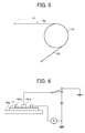
- FIG. 5 illustrates a relationship between the surface resistivity of the intermediate transfer belt 10 and discharge area by the conductive support roller 14.
- the intermediate transfer belt 10 is discharged in a region R1 when the surface resistivity is low, and in a region R2 when the surface resistivity is high.
- the regions R1 and R2 may extend symmetrically.
- an electric charge flows from a portion of the intermediate transfer belt 10 that is not in contact with the support roller 14 to the support roller 14.
- the electric charge flows more easily from the portion of the intermediate transfer belt 10 that is far from the support roller 14. That is, when the intermediate transfer belt 10 has a lower resistivity, the discharge speed is faster because its discharge region is larger.
- the discharge speed is slower and an amount of remaining charge increases.
- the discharge phenomenon is likely to occur between the intermediate transfer belt 10 and an adjacent member while the intermediate transfer belt 10 rotates. The discharge phenomenon is likely to occur when the surface resistivity is over 12.0 log ⁇ /square.
- satisfactory image quality with reduced image failures such as toner scattering may be obtained because the intermediate transfer belt 10 has a surface resistivity within a range from 9.5 log ⁇ /square to 12.0 log ⁇ /square. Further, a high intermediate transfer bias is not necessary and accordingly the power sources 9Y, 9M, 9C, and 9K do not need a large capacity. Further, the discharge phenomenon between the intermediate transfer belt 10 and an adjacent member may be reduced.
- the surface resistivity of the intermediate transfer belt 10 increases due to energization.
- the increase in the surface resistivity is referred to as an amount of surface resistivity change.
- a surface resistivity tolerance of the intermediate transfer belt 10 at the stage of manufacturing is within a range from 9.5 log ⁇ /square to 11.5 log ⁇ /square. If the surface resistivity of the intermediate transfer belt 10 increases half a digit or greater due to energization, the surface resistivity exceeds the 12.0 log ⁇ /square and the discharge phenomenon is likely to occur.
- the amount of surface resistivity change of the intermediate transfer belt 10 is set to 0.5 log ⁇ /square or less during a period from 10 seconds to 5 hours after the start of continuous energization of 500 V.
- a possible way to control the failure due to the increase in surface resistivity is to narrow the tolerance of the surface resistivity to enlarge a safety margin for the increase due to energization.
- a more strict manufacturing control is necessary to narrow the tolerance. This may increase the cost of the intermediate transfer belt 10.
- the intermediate transfer belt 10 comes into a state similar to a state at its replacement time that is after the image forming apparatus 100 outputs 200, 000 to 300, 000 sheets. Therefore, the failure due to an increase in surface resistivity may be prevented till the replacement time of the intermediate transfer belt 10 if the change amount after five hours is 0.5 log ⁇ /square or less.
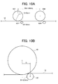
- the surface resistivity of a sample 41 which is produced using a similar material under a similar condition to the material and the condition of the intermediate transfer belt 10, was measured by using a measurement unit illustrated in FIG. 6.
- the measurement unit includes an insulating plate 90a, an ammeter, a power source, and an electrode probe having an inner electrode 101a and a ring electrode 101b.
- the ring electrode 101b is placed at a certain distance from the inner electrode 101a.
- the sample 41 is placed on the insulating plate 90a so that a surface of the sample 41 corresponding to the front surface of the intermediate transfer belt 10 (surface contacting the photoreceptor 40) contacts the plate 90a.
- the inner electrode 101a and the ring electrode 101b are placed on the sample 41.
- the electric current flowing through the ring electrode 101b was measured with the ammeter under the condition that the power source applied a voltage of 500 V to the inner electrode 101a with a load of 2 kg.
- the value calculated based on the measurement value after 10 seconds of the above voltage application is regarded as the surface resistivity of the sample 41. Further, surface resistivity of the sample 41 after 5 hours of the above voltage application was calculated. The amount of surface resistivity change was calculated by deducting the surface resistivity after 10 seconds from the surface resistivity after 5 hours.
- a URS probe with a conductive rubber Hiresta UP Model MCP-HT450URS manufactured by Mitsubishi Chemical Corp.
- a constant voltage power source was used to apply voltage to the inner electrode 101a.
- the values on the ammeter were checked with eyes and by outputting the measurement data to a computer.
- a continuous measurement may be performed with a timer turned off.
- the resistivity measurement may be performed by using the above probe and by externally controlling a constant voltage power source, an ammeter, etc., by a computer.
- FIG. 7 illustrates a part of an intermediate transfer belt 12 around a toner image.
- the intermediate transfer belt 12 is thicker.
- FIG. 8 illustrates a part of an intermediate transfer belt 12a around a toner image.
- the intermediate transfer belt 12a is thinner.
- the intermediate transfer belts 12 and 12a are curved around the toner images at the intermediate transfer nips and have non-contact regions R3 and R4 that are not in contact with the photoreceptors 40, respectively.
- the non-contact region R3 of the thicker intermediate transfer belt 12 is larger than the non-contact region R4 of the thinner intermediate transfer belt 12a. This is because an intermediate transfer belt increases in rigidity and becomes hard to deform, as the intermediate transfer belt becomes thicker.
- the toner image receives a higher nip pressure and the toner agglomerates. As a result, transfer performance is impaired. Particularly, the toner has a higher agglomerating property if the toner has an additive burial rate of 40 percent or more. Therefore, the thicker intermediate transfer belt 12 is not preferable because the nip pressure increases.
- a possible way to reduce the nip pressure to the toner image is to reduce the hardness degree of the intermediate transfer roller 62 and to deform the intermediate transfer roller 62 by a thickness of the toner image. However, the effect is not enough.
- the intermediate transfer belt 12a in FIG. 8 has the smaller non-contact region R4, the nip pressure to the toner image is lower. Therefore, the transfer performance is not impaired.
- the thinner intermediate transfer belt 12a is more stretchy. Accordingly, displacement of color is likely to occur due to the expansion of the intermediate transfer belt 12a.
- a material having a rigidity of 3000 Mpa or greater e. g. , polyimide, polyamide-imide, etc.
- the effect is high when the intermediate transfer belt is thin.
- a single-layered belt including polyimide or polyamide-imide is used as the intermediate transfer belt 10.
- the intermediate transfer belt 10 has a thickness under 40 ⁇ m, the intermediate transfer belt 10 is likely to be stretched. Because displacement of colar is likely to occur, the thickness is not preferable.
- the non-contact region with the photoreceptor 40 becomes larger. Therefore, the nip pressure to the toner image increases and the transfer performance is impaired.
- a polyimide resin is described below as a preferable material for the intermediate transfer belt 10. Because the polyimide resin has a higher strength, the intermediate transfer belt may be thinned by using a polyimide resin.
- Polyimide is generally produced through condensation reaction of an aromatic diamine and an aromatic polyhydric carboxylic anhydride or a derivative thereof.
- polyimide is non-soluble because of its strong principal chain structure. Therefore, firstly a polyimide precursor that is soluble in an organic solvent is synthesized from an acid anhydride and an aromatic diamine. Examples of the polyimide precursor are poly (amic acid) and a polyamic acid.
- molding processing is performed through various methods.
- Polyimide is obtained by cyclodehydrating or imidizing the polyimide precursor with heat or through a chemical method.
- aromatic polyhydric carbolic anhydride examples include ethylene tetracarboxylic acid dianhydride, cyclopentene tetracarboxylic acid dianhydride, pyromellitic dianhydride, 3,3' ,4,4'-benzophenone tetracarboxylic acid dianhydride, and 3,3',4,4'-biphenyl tetracarboxylic acid dianhydride.
- One or a mixture including two or more of the above chemicals may be used.
- aromatic diamine examples include m-phenylenediamine, o-phenylenediamine, p-phenylenediamine, m-aminobenzylamine, p-aminobenzylamine, 4,4'-diaminodiphenylether, 3,3'-diaminodiphenylether, and 3,4'-diaminodiphenylether.
- One or a mixture including two or more of the above chemicals may be used.
- the materials for producing polyimide are not limited to the above examples.
- the above aromatic polyhydric carboxylic anhydride and the aromatic diamine are polymerized in a substantially equimolar organic polar solvent, to obtain a polyimide precursor (e.g., polyamic acid) .
- a polyimide precursor e.g., polyamic acid
- Any organic polar solvent may be used in the polymerization as long as the organic polar solvent dissolves the polyamic acid.
- Preferable organic polar solvent is N,N-dimethyl acetamide and N-methyl-2-pyrrolidone.
- polyimide vanish that is commercially available as a polyamic acid dissolved in an organic solvent may be used.
- examples of polyimide vanish are Torayneece manufactured by Toray Industries Inc., U-Varnish manufactured by UBE INDUCTRIES LTD., Rika-coat manufactured by New Japan Chemical Co., Ltd., Optomer manufactured by JSR Corporation, SE812 manufactured by NISSAN CHEMICAL INDUSTRIES, LTD., and CRC8000 manufactured by SUMITOMO BAKELITE CO., LTD.
- An electron conductive or ion conductive resistance regulator may be added to polyimide to adjust its electric resistance.
- the electron conductive resistance regulator may be metal powder or metal oxide powder.
- metal powder are carbon black, graphite, copper, tin, aluminum, and indium.
- metal oxide powder are tin oxide, zinc oxide, titanic oxide, indium oxide, antimony oxide, bismuth oxide, antimony-doped tin oxide, and tin-doped indium oxide.
- ion conductive resistance regulator examples include tetraalkylammonium salt, trialkylbenzil, ammonium salt, alkyl sulfonate, alkyl benzene sulfonate, alkyl sulfate, glycerin fatty acid ester, sorbitan fatty acid ester, polyoxyethylene alkylamine, polyoxyethylene fatty alcohol ester, alkylbetaine, and lithium perchlorate.
- the resistance regulator is not limited to the above chemical compounds.
- carbon black is preferable for polyimide.
- the polyamic acid obtained in the above method is heated to a range from 200°C to 350°C, and converted into polyimide. Thus, a polyimide resin is obtained.
- the amount of surface resistivity increase of the intermediate transfer belt 10 by continuous energization varies depending on dispersion state of conductive agent.
- the surface resistivity increase may be reduced by enhancing the dispersiveness of conductive agent.
- the toner includes a mother particle having a binder resin and a colorant. At least one inorganic fine particle is externally added to the surface of the mother particle.
- the toner has the additive burial rate of 40 percent or more after the additive is embedded through the following method.
- the embedding of additive was performed using a polyethylene ointment bottle whose capacity is within a range from 300 ml to 500 ml. In the bottle, 10 grams of toner and 100 grams of resin-coated ferritic carrier were mixed with a tubular mixer for 30 minutes at a speed of 100 rpm. Through the above process, the embedding of the additive to the toner mother particle saturates and is settled.
- the ferritic carrier used in an exemplary embodiment was EF963-60B that is coated with a silicone resin and manufactured by Powder-Tech Co. Ltd., and has a particle size within a range from 35 ⁇ m to 85 ⁇ m.
- Wab tubular mixer T2F manufacture by Willy A Bachofen AG was used as the tubular mixer.
- 300 ml of water is added in the ointment bottle.
- the mixture in the ointment bottle was slightly agitated to separate the toner and the carrier in the water.
- the toner dispersion liquid, the supernatant solution in the ointment bottle, was filtered.
- the filtered toner was dried under a reduced pressure at room temperature. Thus, the toner to which the additive was embedded was obtained.
- a specific surface area of the toner by the BET method was measured before and after the embedding of additive by using TriStar3000, an automatic analyzer for specific surface are and fine pores distribution, manufactured by SHIMADZU CORPORATION.
- One gram of toner was put into a specially designed cell. The cell was deaerated by Vacprep 061, a degassing device manufactured by SHIMADZU CORPORATION dedicated for a TriStar, for 20 hours under a reduced pressure of 100 mTorr or less at room temperature. With the specially designed cell, the BET specific surface area may be automatically obtained by TriStar 3000. Nitrogen gas was used as an absorption gas.
- FIG. 9 illustrates a relation between the BET specific surface area and the agitation time of toner with carrier in the polyethylene ointment bottle.
- the vertical axis shows the BET specific surface area and the horizontal axis shows the agitation time.
- any toner produced through a known method may be used.
- known materials may be used.
- binder resin examples include a polyester resin, a styrene resin, an acrylic resin, a styrene-acrylic resin, a polyol resin, and an epoxy resin.
- the polyester resin is preferable from the viewpoint of fixing property at lower temperature.
- the binder resin having a glass transition point (Tg) within a range from 40°C to 75°C is used.
- the Tg is within a range from 45°C to 65°C.
- the glass transition point may be measured by a differential scanning calorimeter (DSC).
- DSC differential scanning calorimeter
- the glass transition point was obtained based on a glass transitionpoint curvemeasuredwith DSC-60Amanufactured by SHIMADZU CORPORATION, with a temperature increase rate of 10°C per minute.
- colorant known dyes and pigments may be used.
- colorant are carbon black, naphthol yellow, Hansa yellow, permanent red, oil red, quinacridone red, phthalocyanine blue, and anthraquinone blue.
- the colorant is not limited to the above examples.
- the toner may further include a releasing agent.
- a known releasing agent for example, polyethylene wax, polypropylene wax, paraffin wax, etc.
- the toner may include a charge adjuster, as required.
- a known charge adjuster for example, a nigrosine dye, a triphenyl methane dye, etc.
- the amount of charge adjuster depends on the toner manufacturing conditions including type of binder resin, additives, and the method of dispersion.
- the inorganic fine particle is added to the toner, to enhance its flow characteristic, developing characteristic, and charge characteristic.
- the inorganic fine particle preferably has an average primary particle size within a range from 5 nm to 2 ⁇ m.
- the ratio of inorganic fine particle to toner particle which depends on type thereof, is often within a range from 0.01 weight percent to 5 weight percent.
- examples of inorganic fine particle are silica, alumina, titanium oxide, barium titanate, and magnesium titanate.
- the above inorganic fine particles may be used singly or in combination.
- a toner including a polyester resin as its binder is manufactured through an ester extension polymerization method.
- the ester extension polymerization method is described below. Firstly, an organic solvent phase including a polyester prepolymer is dispersed in an aqueous medium phase with an active hydrogen-containing compound. After an extension reaction and/or a cross-linking reaction occurs in the aqueous medium, the organic solvent is removed and toner particles are obtained. The toner particles are washed and dried into toner particle powder. This method excels in granulation performance and easily controls particle size, particle size distribution, and shape.
- polyester prepolymer forms a toner binder (binder resin) having a higher molecular weight through the extension reaction and/or cross-linking reaction with the active hydrogen-containing compound in the aqueous medium.
- polyester prepolymer include polyester prepolymers having a functional group that reacts to an active hydrogen (reactive polyester prepolymer).
- a polyester prepolymer having an isocyanate group as the active hydrogen is preferable.
- the polyester prepolymer is produced by reacting polyisocyanate (PIC) with a polyester that is a polycondensation product of polyol (PO) and polycarboxylic acid (PC) and includes an active hydrogen group.
- PIC polyisocyanate
- PO polyol
- PC polycarboxylic acid
- active hydrogen group examples of the above polycondensation product are bisphenol A alkylene oxide adduct, dicarboxylic acids (e.g., succinic acid, adipic acid, maleic acid, fumaric acid, phthalic acid, and terephthalic acid), and polycarboxylic acids having more than three function groups (e.g., trimellitic acid and pyromellitic acid).
- dicarboxylic acids e.g., succinic acid, adipic acid, maleic acid, fumaric acid, phthalic acid, and terephthalic acid
- polycarboxylic acids having more than three function groups e.g., trim
- polyisocyanate examples include aliphatic polyisocyanates, alicyclic polyisocyanates, aromatic diisocyanates, aromatic aliphatic diisocyanates (e.g., ⁇ , ⁇ , ⁇ ', ⁇ '-tetramethylxylylene diisocyanate), isocyanurate, and a product produced by blocking the polyisocyanate with a phenol derivative, oxime, caprolactam, etc.
- Examples of aliphatic polyisocyanate are tetramethylene diisocyanate,hexamethylene diisocyanate,and2,6-diisocyanate methylcaproate.
- Examples of alicyclic polyisocyanates are isophorone diisocyanate and cyclohexylmethane diisocyanate.
- Examples of aromatic diisocyanates are tolylene diisocyanate and diphenylmethane diisocyanate. The above materials may be used singly or in combination.
- the polyester prepolymer having isocyanate group generally includes more than one isocyanate group per molecule.
- the polyester prepolymer preferably has an average of 1.5 to 3 isocyanate groups per molecule, and more preferably has an average of 1.8 to 2.5 isocyanate groups per molecule. If the amount of isocyanate group is less than one per molecule, the molecular weight of polyester after extension reaction is not high enough. As a result, the toner has poor resistance to hot offset.
- the hot offset is a phenomenon wherein overheated toner adheres to a heating roller during a fixing process and causes an image defect.
- the polyester prepolymer is dissolved in the organic solvent phase as described above.
- the polyester prepolymer content in toner mother particle is within a range from 10 weight percent to 55 weight percent.
- the polyester prepolymer content is preferably 10 weight percent to 40 weight percent, and more preferably 15 weight percent to 30 weight percent.
- a non-reactive polyester may be used in combination with the above reactive polyester prepolymer, and may be dissolved in the organic solvent phase in combination with the reactive polyester prepolymer.
- the combined use is preferred to the single used of the reactive polyester prepolymer. The reason is that the fixing property at a lower temperature and gloss in full color image of toner are enhanced.
- non-reactive polyester examples are a polycondensation product of polyol (PO) and polycarboxylic acid (PC), etc., similarly to the reactive polyester prepolymer that is used in the reaction with polyisocyanate (PIC).
- PIC polyisocyanate
- the weight ratio of the non-reactive polyester to the reactive polyester prepolymer is from 10 : 90 to 55 : 45.
- the above weight ratio is preferably from 10 : 90 to 40: 60, and more preferably from 15 : 85 to 30 : 70.
- the toner may further include another known binder resin (e.g., styrene resin, acrylic resin, epoxy resin, styrene-acrylic acid ester copolymer, etc).
- binder resin e.g., styrene resin, acrylic resin, epoxy resin, styrene-acrylic acid ester copolymer, etc.
- amines are preferable.
- a urea modified polyester resin is produced by the reaction of an amine with the isocyanate group in the polyester prepolymer.
- amines are diamine, a polyamine having three or more amino groups, amino alcohol, amino mercaptan, amino acids, and materials obtained by blocking the amino groups of the above amines.
- Preferred examples are 4,4'-diamino diphenylmethane, isoholon diamine, hexamethylene diamine, ethanolamine, aminoethyl mercaptan, aminopropionic acid, and a ketimine compound obtained by blocking amino groups of the above with a ketone (e.g., methylethyl ketone).
- the colorant or colorant master batch is preferably dissolved or dispersed in the organic solvent phase preliminary together with the reactive polyester prepolymer and the non-reactive polyester. Further, the release agent and/or the charge adjuster may be dissolved or dispersed in the organic solvent phase, as required.
- the aqueous medium phase can include water. Further, an organic solvent may be used in combination with water. It is preferable to use an organic solvent to which the resinous principle of the organic solvent phase is dissolvable, to lower viscosity of the aqueous medium when the resinous principle is dispersed into the aqueous medium.
- the organic solvent preferably has a boiling point less than 100°C to be easily distilled away.
- organic solvent examples include, but are not limited to, toluene, xylene, benzene, carbon tetrachloride, methylene chloride, 1,2-dichloroethane, 1,1,2-trichloroethane, trichloroethylene, chloroform, monochlorobenzene, dichloroethylidene, methylacetate,ethylacetate, methylethyl ketone, and methyl isobutyl ketone. These organic solvents can be used alone or in combination.
- the particulate resin is used for controlling the shape of toner (e.g., roundness, particle size distribution, etc.), and unevenly adheres on the surface of the toner particle. Any resin that forms a dispersion element in the aqueous medium can be used as the particulate resin.
- the resin can be thermoplastic or thermoset.
- the resin include vinyl resins, polyurethane resins, epoxy resins, polyester resins, polyamide resins, polyimide resins, silicone resins, phenol resins, melamine resins, urea resins, aniline resins, ionomer resins, and polycarbonate resins. These can be used alone or in combination.
- vinyl resins, polyurethane resins,epoxy resins,polyester resins,and combinations thereof are preferably used.
- vinyl resins include, but are not limited to, homopolymers and copolymers of vinyl monomers such as styrene-(meth)acrylate copolymers, styrene-butadiene copolymers, (meth)acrylic acid-acrylate copolymers, styrene-acrylonitrile copolymers, styrene-maleic anhydride copolymers, and styrene-(meth)acrylic acid copolymers.
- vinyl monomers such as styrene-(meth)acrylate copolymers, styrene-butadiene copolymers, (meth)acrylic acid-acrylate copolymers, styrene-acrylonitrile copolymers, styrene-maleic anhydride copolymers, and styrene-(meth)acrylic acid copolymers.
- the dispersion ratio of the particulate resin in the aqueous medium is preferably within a range from 0.5 weight percent to 10 weight percent with respect to the organic solvent phase. If the ratio is out of the above range, emulsification is hindered and granulation may not be obtained. The more preferable range is from 1 weight percent to 3 weight percent.
- a mean particle size of the particulate resin is within a range from 5 nm to 200 nm from the viewpoint of granulation. The mean particle size is preferably within a range from 20 nm to 300 nm.
- the particulate resin preferably has a glass transition point within a range from 40°C to 90°C, from the viewpoint of fixing property at low temperature and storage stability. The glass transition point is more preferably within a range from 50°C to 70°C.
- the organic solvent phase and the amine dispersion can be stably formed in the aqueous medium, through a known dispersion method using shearing force, etc.
- the dispersion method include, but are not limited to, a low-speed shearing method, a high-speed shearing method, a friction method, a high-pressure jet method, and an ultrasonic method.
- a disperser may be used as required to stably form the organic solvent phase and the amine dispersion in the aqueous medium.
- examples of disperser include anionic surfactants such as alkylbenzene sulfonic acid salts, ⁇ -olefin sulfonic acid salts and phosphoric acid salts; cationic surfactants of quaternary ammonium salts type such as alkyltrimethyl ammonium salts, dialkyldimethyl ammonium salts, alkyldimethyl benzyl ammonium salts; nonionic surfactants such as fatty acid amide derivatives, polyhydric alcohol derivatives;andampholytic surfactants such as alanine, dodecyldi(aminoethyl)glycin, and di(octylaminoethyl)glycine.
- the image forming apparatus 100 uses the two-component developer produced by mixing the above toner and the magnetic carrier.
- the content of toner in the developer is preferably within a range from 1 part by weight to 10 parts by weight, per 100 parts by weight of the carrier.
- the content of toner is more preferably within a range from 5 parts by weight to 10 parts by weight.
- the magnetic carrier may be a known material such as iron powders, ferrite powders, magnetite powders, and magnetic resin carriers.
- the magnetic carrier may be coated with a resin such as amino resins(e.g.,urea-formaldehyderesins,melamine resins, benzoguanamine resins, urea resins, polyamide resins, epoxy resins), polyvinyl resins, and polyvinylidene resins.
- polyvinyl resins and polyvinylidene resins are acrylic resins, polymethyl methacrylate resins, polyacrylonitrile resins, polyvinyl acetate resins, polyvinyl alcoholic resins, polyvinyl butyral resins, polystyrene resins, and polystyrene resins (e.g., styrene-acryl copolymer).
- examples of the coating resin include halogenoid olefin resins (e.g., polyvinyl chloride), polyester resins (e.g., polyethylene terephthalate resins, polybutylene terephthalate resins), polycarbonate resins, polyethylene resins, polyvinyl fluoride resins, polyvinylidene fluoride resins, polytrifluoro ethylene resins, polyhexafluoro propylene resins, copolymers of vinylden fluoride and acryl monomer, copolymers of vinylden fluoride and vinyl fluoride, fluoroterpolymers (e.g., terpolymers of tetrafluoroethylene, vinylden fluoride, and non-fluorinated monomer), and silicone resins.
- halogenoid olefin resins e.g., polyvinyl chloride
- polyester resins e.g., polyethylene terephthalate resins, polybutylene ter
- the coating resin can include a conductive powder, etc. , as required.
- conductive powder are metal powders, carbon black, titanium oxide, tin oxide, and zinc oxide.
- the conductive powder preferably has a mean particle size less than 1 ⁇ m. When the conductive powder has a mean particle size over 1 ⁇ m, control of electric resistance is difficult.
- the mixture is agitated with Aquamizer manufactured by Hosokawa Micron Corporation.
- Aquamizer manufactured by Hosokawa Micron Corporation.
- polyamic acid having 18 percent of solid content as precursor of polyimide resin was prepared.
- the polyamic acid obtained as above was molded into a ring through a centrifugal molding method while a metal cylindrical mold having a diameter of 250 mm was rotated at a speed of 100 rpm, and polyamic acid having a solid content of 18% was uniformly applied to an inner surface of the cylindrical mold by a dispenser.
- the cylindrical mold was rotated at a speed of 1000 rpm for 5 minutes to level the polyamic acid.
- the rotation speed was reduced to 300 rpm, and the cylindrical mold was gradually heated to 130°C.
- the polyamic acid was dried for 40 minutes and was solidified. After the solidification, the cylindrical mold was stopped to rotate and heated to 350 °C, to cause imide ring-closing. Thus, imidization was completed and polyimide coating was obtained.
- the cylindrical mold was cooled to room temperature and the polyimide coating was removed therefrom. Both edges of the polyamic coating were cut off so that the polyamic coating had a width of 250 mm. From the above, a seamless intermediate transfer belt 10a was produced.
- the intermediate transfer belt 10a was adjusted to have a layer thickness of 82 ⁇ m, a surface resistivity of 10.4 4 log ⁇ /square, and an elasticity of 4200 Mpa.
- the layer thickness is adjustable by controlling the amount of polyamic acid applied by the dispenser.
- the surface resistivity is adjustable by adjusting the amount of a conductive agent, etc.
- another polyamic acid solution using 4,4'-diaminodiphenylether which is different from the aromatic diamine used to produce the above polyamic acid solution, was mixed with the above polyamic acid solution.
- the elasticity is adjustable to control the mixing ratio of the polyamic acid solution using 4, 4' -diaminodiphenylether and the polyamic acid solution using p-phenylenediamine.
- intermediate transfer belts 10b to 10i were produced.
- the intermediate transfer belts 10b to 10i were adjusted to have an elasticity of 4200 Mpa.
- the intermediate transfer belts, except for the intermediate transfer belt 10e, had a surface resistivity change amount of 0.2 log ⁇ /square in a continuous measurement from 10 seconds to 5 hours after the start of the voltage application.
- the dispersion condition of the intermediate transfer belt 10e was lower than other intermediate transfer belts, and the intermediate transfer belt 10e had a surface resistivity change amount of 0.5 log ⁇ /square in a continuous measurement from 10 seconds to 5 hours after the start of the voltage application.
- Intermediate transfer belts 10j to 10p having different layer thickness were produced by changing the amount of polyamic acid applied to the cylindrical mold by the dispenser.
- the intermediate transfer belts 10j to 10p had a surface resistivity of 11.1 log ⁇ /square, an elasticity of 4200 Mpa, and a surface resistivity change amount of 0.2 log ⁇ /square in a continuous measurement from 10 seconds to 5 hours after the start of the voltage application.
- the elasticity was based on JIS-K7113.
- a milky liquid was prepared by mixing 950 parts of water, 20 parts of a vinyl resin (copolymer of sodium salt of styrene-methacrylic acid-butyl acrylate-methacrylic acid ethylene oxide adduct sulfate ester) water dispersion (by Sanyo Chemical Industries Ltd.), 16 parts of a 48.5% solution of a sodium salt of dodecyl diphenyl ether disulfonic acid (ELEMINOL MON-7 from Sanyo Chemical Industries Ltd.), 12 parts of 3.0 % solution of a polymer protective colloid, carboxymethylcellulose, (CELLOGEN BSH from Sanyo Chemical Industries Ltd.), and 130 parts of ethyl acetate. This milky liquid was used as a water phase.
- a mixture of 1200 parts of water, 50 parts of carbon black (REGAL 400R from Cabot Corporation), 50 parts of a polyester resin (RS801 having a weight-average molecular weight of 19, 000 and a Tg of 64°C, from Sanyo Chemical Industries Ltd.), and 30 parts of water was agitated with HENSCHEL MIXER manufactured by Mitsui Mining Co, Ltd.
- the mixture was kneaded for 30 minutes at 150°C with a two-roll mill and extended and cooled.
- the mixture was further pulverized by a pulverizer.
- a carbon black master batch was obtained.
- a polyester resin (RS801 having a weight-average molecular weight of 19,000 and Tg of 64°C, from Sanyo Chemical Industries Ltd.), 30 parts of carnauba wax, and 850 parts of ethyl acetate were agitated at 80 °C.
- the reaction vessel was kept at 80°C for 5 hours, and then cooled to 30°C over 1 hour.
- 1,780 parts of the above oil phase 100 parts of a 50% ethyl acetate solution of a polyester prepolymer (having a number average molecular weight of 3,800, a weight-average molecular weight of 15,000, and a Tg of 60°C, from Sano Chemical Industries Co., Ltd.), 15 parts of isobutyl alcohol, and 7.5 parts of isoholon diamine were mixed in the reaction vessel.
- the mixture was agitated for 1 minute at a rotation speed of 6, 000 rpm with TK HOMOMIXER (manufactured by Tokushu Kika Kogyo K.K). Further, 1200 parts of wafer phase was added to the reaction vessel and then the mixture was agitated for 20 minutes at a rotation speed of 7,500 rpm with TK HOMOMIXER, to obtain an aqueous medium dispersion liquid.
- aqueous medium dispersion liquid was kept at a temperature of 30°C for 12 hours in a reaction vessel equipped with a stirrer and a thermometer, to remove the organic solvent, and then aged for 8 hours at a temperature of 45°C.
- a dispersion liquid without organic solvents was obtained.
- 100 parts of the dispersion liquid was filtered to obtain a wet cake.
- the wet cake was mixed with 500 parts of ion-exchange water with TK HOMOMIXER for 10 minutes at a rotation speed of 12,000 rpm. The mixture was further filtered under a reduced pressure.
- the wet cake was dried for 48 hours at a temperature of 45°C with a circulating air drier, and then sieved with a screen having openings of 75 ⁇ m.
- a mother toner particle was prepared.
- the toner A was prepared by mixing 100 parts of the above toner mother particles, 1.2 parts of a hydrophobic Silica having an average primary particle size of about 12 nm as an external additive (from Clariant Japan Co. Ltd.), 0.5part of a hydrophobic titanium oxide having an average primary particle size of about 12 nm (from TAYCA CAORPORATION), and 0.8 part of a hydrophobic silica having an average primary particle size of about 120 nm (from Shin-Etsu Chemical Co., Ltd.) with HENSCHEL MIXER. The mixture was filtered with a screen having an opening of 38 ⁇ m to remove agglomerate materials.
- the toner A had a weight-average particle size (D4) of 5.8 ⁇ m, a number-average particle size (Dn) of 5.1 ⁇ m, a mean roundness of 0.97, and an additive burial ratio X of 42%.
- the toner B was prepared through the procedure for preparing the toner A. However, 500 parts of a polyester resin having a number-average molecular weight of 9,800, a weight-average molecular weight of 33,000, and a Tg of 68 °C (from Sanyo Chemical Industries Co., Ltd.) was used instead of 500 parts of RS801 having a weight-average molecular weight of 19, 000 and Tg of 64°C (from Sanyo Chemical Industries Co., Ltd) .
- the toner B had a weight-average particle size (D4) of 5.9 ⁇ m, a number-average particle size (Dn) of 5.2 ⁇ m, a mean roundness of 0.97, and an additive burial ratio of 30%.
- the toner C was prepared through the procedure for preparing the toner A. However, 500 parts of a polyester resin having a number-average molecular weight of 2,500, a weight-average molecular weight of 6,700, and a Tg of 44°C (from Sanyo Chemical Industries Co., Ltd.) was used, instead of 500 parts of RS801 (from Sanyo Chemical Industries Co., Ltd) .
- the toner B had a weight-average particle size (D4) of 5.8 ⁇ m, a number-average particle size (Dn) of 5.1 ⁇ m, a mean roundness of 0.97, and an additive burial ratio of 70%.
- the toner D was prepared through the procedure for preparing the toner A. However, 500 parts of a polyester resin having a weight-average molecular weight of 12,000 and Tg of 56°C (from Sanyo Chemical Industries Co. , Ltd.) was used, instead of 500 parts of RS801 (from Sanyo Chemical Industries Co. , Ltd) .
- the toner B had a weight-average particle size (D4) of 5.7 ⁇ m, a number-average particle size (Dn) of 5.1 ⁇ m, a mean roundness of 0.98, and an additive burial ratio of 56%.
- the toner E was prepared through the procedure for preparing the toner A. However, 500 parts of a polyester resin having a weight-average molecular weight of 27,000 and Tg of 66°C (from Sanyo Chemical Industries Co. , Ltd.) was used, instead of 500 parts of RS801 (from Sanyo Chemical Industries Co. , Ltd) .
- the toner B had a weight-average particle size (D4) of 5.7 ⁇ m, a number-average particle size (Dn) of 5.1 ⁇ m, a mean roundness of 0.98, and an additive burial ratio of 38%.
- the weight-average particle size (D4) and number-average particle size (Dn) were measured by using COULETR MULTISIZER II manufactured by Coulter Electrons Inc. The number of particles to be counted was set to 50, 000. Themeasurementmethod is described below.
- a dispersant 0.1 to 5 ml of a surfactant is added to 100 ml to 150 ml of an electrolyte.
- a preferable surfactant is alkylbenzene sulfonate.
- the electrolyte a 1% NaCl aqueous solution including a first grade sodium chloride such as ISOTON-II (from Coulter Electrons Inc.) is used.
- 2 mg to 20 mg of toner particles to be measured is added to the electrolyte and dispersed by an ultrasonic dispersing machine for about 1 minute to 3 minutes to prepare a toner suspension liquid.
- the volume and the number of toner particles are measured by the above instrument using an aperture of 100 ⁇ m to determine the distribution thereof.
- the weight average particle size (D4) and the number average particle diameter (Dn) are available based on the distribution.
- the mean roundness was measured by using a flow-type particle image analyzer, FPIA-2100 (manufactured by Sysmex Corp.), and an analyzing software, FPIA-2100 Data processing Program for FPIA version 00-10.
- the method is described below. Firstly, 0.1 ml to 0.5 ml of a 10 weight percent solution of a surfactant (alkylbenzene sulfonate NEOGEN SC-A from Dai-ichi Kogyo Seiyaku Co., Ltd.) was put in a 100 ml glass beaker. Further, 0. 1 g to 0.
- a surfactant alkylbenzene sulfonate NEOGEN SC-A from Dai-ichi Kogyo Seiyaku Co., Ltd.
- the amount of surfactant varies depending on the hydrophobic property of toner, similarly to the toner particle size measurement. When the amount of surfactant is excessive, noise is generated due to foam. When the amount is insufficient, toner is not wet enough and dispersion is not sufficient.
- the amount of toner varies depending on its particle size. The amount is reduced when the particle size is smaller, and is increased when the particle size is larger.
- the density of the dispersion liquid can be set in a range from 5,000 to 15, 000 particles per ⁇ l, by adding 0.1 g to 0.5 g of the toner.
- FIG. 10A and 10B are for explaining a positional relationship between the photoreceptor 40 and the intermediate transfer roller 62.
- the photoreceptor had a diameter (A) of 40 mm.
- the intermediate transfer roller 62 had a diameter (B) of 16 mm.
- the distance between the centers of photoreceptors 40 (Wd) was 100 mm.
- a distance between the centers of the photoreceptor 40 and the intermediate transfer roller 62 in a belt moving direction is determined as distance D.
- a width Wn of the intermediate transfer nip was measured as follows. Firstly, a uniform toner image was formed on the intermediate transfer belt 10. The image forming apparatus 100 was turned off before the toner image was transferred onto a sheet. Next, the transfer unit 11 (FIG. 2) was detached from the image forming apparatus 100. The intermediate transfer belt 10 was manually moved so that the toner image was at a position corresponding to a portion of the photoreceptor 40 at which the intermediate transfer nip was measured. A driving gear, etc., were removed to prevent the intermediate transfer belt 10 from rotating. After an electrode, etc., were removed not to apply voltage to the intermediate transfer rollers 62, the transfer unit 11 was attached to the image forming apparatus 100.
- the image forming apparatus 100 was powered on so that the photoreceptor 40 was rubbed with the intermediate transfer belt 10 that is in a halting state. Thus, a scraping mark was formed on the toner image.
- the photoreceptor 40 may be manually rotated from outside.
- the transfer unit 11 was detached from the image forming apparatus 100. The width Wn of the intermediate transfer nip was measured based on the scraping mark.
- the width Wn was adjusted to 2 . 5 mm, by changing the contact pressure and digging amount of the intermediate transfer rollers 62 to the photoreceptors 40, etc.
- the contact pressure is hereinafter referred to as roller contact pressure.
- the intermediate transfer roller 62 held by the holder illustrated in FIG. 4 was used. That is, the intermediate transfer roller 62 was held by the bearing 62a contacting the upper surface of the long hole 71.
- the roller contact pressure was set to 2.5 N/cm.
- an intermediate transfer roller 62 held by a holder illustrated in FIG. 11 was used.
- the holder is provided on a frame 70a and includes a bearings 62a, springs 62b, and long holes 71a.
- An upper side of the frame 70a is open.
- the intermediate transfer rollers 62 is configured to dig in the intermediate transfer belt 10 to an amount of 0.5 mm.
- a contact position of the intermediate transfer roller 62 with the intermediate transfer belt 10 is shown by a value of the distance D, and hereinafter referred to as roller contact position.
- the roller contact position value is positive when the contact position is downstream of the center of the photoreceptor 40, and is negative when the contact position is upstream of the center of the photoreceptor 40, in the belt moving direction.
- intermediate transfer bias conditions was set so that a transfer rate of 93% was obtained. That is, the transfer rate was repeatedly measured with different amounts of transfer current. Based on the result, the amount of transfer current was determined.
- the transfer rate is obtained as follows. Firstly, a plurality of single color images having substantially the same shape are formed on the intermediate transfer belt 10 in line along a moving direction of the intermediate transfer belt 10. The larger the images are, the higher the measurement accuracy is. However, it is necessary to change the shape depending on the diameter of the photoreceptor 40.
- the power is turned off when the first image is transferred onto the intermediate transfer belt 10 and the last image is formed on the photoreceptor 40.
- the photoreceptor 40 and the transfer unit 11 are detached from the image forming apparatus 100.
- the toner on the photoreceptor 40 and the intermediate transfer belt 10 is vacuumed via a filter and the amounts thereof are measured, respectively.
- the transfer rate is calculated by the following formula 4, Bt / Kt ⁇ 100 wherein Bt is the amount of toner on the intermediate transfer belt 10 and Kt is the amount of toner on the photoreceptor 40.
- the rate of reverse transfer was obtained as follows. Firstly, a plurality of single color images having a substantially same shape are formed on the intermediate transfer belt 10 in line along a moving direction of the intermediate transfer belt 10. The larger the images are, the higher the measurement accuracy is. However, it is necessary to change the shape depending on the diameter of the photoreceptor 40.
- the power is turned off after the first image passed a first and a second process unit.
- the transfer unit 11 is detached from the image forming apparatus 100.
- the toner on the intermediate transfer belt 10 is vacuumed via a filter, and the amounts of toner after passing one transfer nip and after passing two transfer nips are measured, respectively.
- the reverse transfer rate is calculated by the following formula 5, Bt ⁇ 1 - Bt ⁇ 2 / Bt ⁇ 1 ⁇ 100 wherein Bt1 is the amount of toner after passing one transfer nip and Bt2 is the amount of toner after passing two transfer nips.
- a filled-in image was formed with the transfer current determined under the condition of example 1, shown in table 1.
- the filled-in image was checked with eyes for density unevenness.
- the transfer property of the filled-in area was judged as "good” when there was no density unevenness, "average” when there was slight density unevenness, and "bad” when there was unacceptable clear density unevenness.
- toner scattering level In the evaluation of the toner scattering level, an image of black letters was formed. Toner scattering around the letters was checked with eyes through a 20-power loupe. The scattering level was judged as "good” when almost no toner scattering was observed though the 20-power loupe, "average” when some toner scattering was observed though the 20-power loupe and almost no toner scattering was observed without the loupe, and "bad” when some toner scattering was observed without the loupe.
- the fixing property was evaluated based on a filled-in image after the fixing process.
- the fixing property was judged as "good” when a sheet having an image was folded in two and no toner fell off therefrom, "average” when the image was scratched with a nail and some toner fell off therefrom, and "bad” when the image was rubbed with a finger and some toner fell off therefrom.
- a half-tone image was formed across the full width of a sheet and was continuously printed for 50 sheets.
- the half-tone images were checked for a discharge image.
- the discharge image is a defect that a circle-like pattern occurs in a half-tone or filled-in image due to discharge phenomenon as illustrated in FIG. 12.
- the shape of the discharge image varies depending on discharge polarity, etc.
- the discharge image level was judged as "good” when there was no discharge image, "average” when discharge images were observed on 5 sheets or less, "bad” when discharge images were observed on 6 sheets or more.
- comparative example 1 used the toner B having an additive burial rate of 30% and had a "bad" level of fixing property, even if the fixing temperature was raised to 150°C.
- comparative example 3 and examples 1 to 3 using the toner having additive burial rate of 42% or more the fixing property was good even if the fixing temperature was as low as 140°C.
- the roller contact position which is equivalent to the value of the distance between the centers of the intermediate transfer roller 62 and the photoreceptor 40 in the belt moving direction, was 2.2 mm.
- the value of the roller contact position was 2.7 mm.
- the reverse transfer rate in comparative example 3 was 6.8, which was worse than the reverse transfer rate in examples 1 to 3.
- the intermediate transfer nip is formed when the intermediate transfer roller 62 pressed the intermediate transfer belt 10 to be wound around the photoreceptor 40. Therefore, most of the intermediate transfer nip is located upstream of the center of the photoreceptor 40 in the belt moving direction.
- the distance between the centers of the intermediate transfer roller 62 and the photoreceptor 40 was 2.2 mm and was smaller than the intermediate transfer nip having a width of 2.5 mm. That is, the intermediate transfer nip was formed by the photoreceptor 40 and the intermediate transfer roller 62 that sandwiched the intermediate transfer belt 10a. Comparative example 3 did not satisfy the relationship between the intermediate transfer roller 62, photoreceptor 40, and the intermediate transfer belt 10a shown by formula 2, L > A / 2 + B / 2 + C .
- the distance between the centers of the intermediate transfer roller 62 and the photoreceptor 40 was 2. 7 mm and was larger than the intermediate transfer nip having a width of 2.5 mm.
- the positional relationship shown by formula 2 was satisfied and the intermediate transfer roller 62 did not contact the photoreceptor 40 via the intermediate transfer belt 10a.
- the nip pressure was higher in comparative example 3 than the nip pressure in examples 1 to 3, because the intermediate transfer roller 62 and the photoreceptor 40 sandwiched the intermediate transfer belt 10a to from the intermediate transfer nip in comparative example 3 .
- the toner having an additive burial rate of 40% or more has an increased agglomerating property.
- the toner having an additive burial rate of 40% or more is used in comparative example 3, more toner on the intermediate transfer belt 10a agglomerates at the intermediate transfer nip and the transfer property was degraded. Therefore, a higher voltage was applied to the intermediate transfer roller 62 to obtain a transfer rate of 93% or more.
- the intermediate transfer roller 62 was placed upstream of the center of the photoreceptor 40 by 1 mm. Therefore, voltage at an entrance of the intermediate transfer nip was higher and an abnormal discharge phenomenon occurred. As a result, the toner scattering level on the image was bad, as shown in table 2.
- the value of the roller contact position was 10.5 mm, which was larger than one-tenth of the distance between the photoreceptors 40 (Wd), and the transfer property of the filled-in area was bad. It seemed that the leak current flowing toward the downstream intermediate transfer nip in the belt moving direction increased because the distance between intermediate transfer roller 62 and the center of the photoreceptor 40 was larger than 10 mm (Wd/10). As a result, an optimum transfer condition was not obtained and the transfer property of the filled-in area was degraded. To the contrary, in examples 4 and 5, the distance between intermediate transfer roller 62 and the center of the photoreceptor 40 was not greater than one-tenth of the distance between the photoreceptors 40 (Wd). Therefore, the leak current flowing toward the downstream intermediate transfer nip in the belt moving direction was reduced and a better transfer property of the filled-in area was obtained.
- the intermediate transfer belts 10b and 10c having surface resistivity under 9.5 log ⁇ /square were used in comparative examples 6 and 7. Because each of the intermediate transfer belts 10b and 10c had a high potential at the entrance of the intermediate transfer nip, toner was transferred in the gap located at the entrance of the intermediate transfer nip. Therefore, the toner scattering level was not good in each of comparative examples 6 and 7.
- the intermediate transfer belts 10f and 10g having surface resistivity over 12 log ⁇ /square were used in comparative examples 8 and 9.
- a higher voltage was applied to the intermediate transfer roller 62 in each of comparative examples 8 and 9 to obtain a transfer rate of 93%, because the surface resistivity of the intermediate transfer belts 10f or 10g was high. Therefore, the electric potential at the exit of the intermediate transfer nip increased, which invited an abnormal discharge phenomenon in the gap at the exit of the intermediate transfer nip.
- the toner image on the intermediate transfer belt 10f or 10g was disturbed due to the abnormal discharge phenomenon and discharge image level was bad in each of the comparative examples 8 and 9.
- the transfer property of the filled-in area was bad in comparative examples 10 and 11 using the intermediate transfer belts 10o and 10p whose thicknesses were over 100 ⁇ m. It seemed that the pressure to the toner at the intermediate transfer nip increased because the intermediate transfer belts 10o and 10p were thicker. That is, the toner A having an additive burial rate of 40% or more agglomerated when the pressure to the toner A increased, because of its increased agglomeration property. Therefore, the transfer property of the filled-in area was degraded.
- the reverse transfer rate was over 7.0% in comparative examples 10 and 11, which was higher than other examples.
- the reason may be as follows. A higher voltage was applied to the intermediate transfer roller 62, to obtain a transfer rate of 93% in each of comparative examples 10 and 11, because the reverse transfer rate was bad. However, when the voltage was increased, the toner on the intermediate transfer belts 10o and 10p were reversely charged while passing through a plurality of intermediate transfer nips. Therefore, more toner was reversely transferred from the intermediate transfer belt 10o or 10p to the photoreceptor 40, which resulted in the reverse transfer rate of 7.0% or more.
- the transfer rate of the filled-in area was good in examples 10 to 14 using the intermediate transfer belts 10 j to 10n whose thicknesses were under 100 ⁇ m. Therefore, the reverse transfer rate was reduced and satisfactory image quality was obtained, because a high transfer bias was not necessary.
- the image forming apparatus maymelt the toner at a lower temperature by using the toner having an additive burial rate of 40% or more. Therefore, energy required in the fixing process may be reduced, which leads to power-saving by the image forming apparatus.
- the intermediate transfer roller 62 as a bias applying roller, is placed on a plane perpendicular to an axis direction of the intermediate transfer belt 10, as an endless belt, along a vertical plane so that the following relation is satisfied, L > A / 2 + B / 2 + C .
- L is a distance between axis centers of the photoreceptor 40, as an image carrier, and the intermediate transfer roller 62
- A is a diameter of the photoreceptor 40
- B is a diameter of the intermediate transfer roller 62
- C is a thickness of the intermediate transfer belt 10. Therefore, the intermediate transfer roller 62 is placed at a position not contacting the photoreceptor 40 via the intermediate transfer belt 10.
- the intermediate transfer nip is formed where the intermediate transfer belt 10 winds around the photoreceptor 40.
- the nip pressure at the above intermediate transfer nip is lower compared with the nip pressure at the intermediate transfer nip formed by the photoreceptor 40 and the intermediate transfer roller 62 that sandwich the intermediate transfer belt 10. Therefore, toner agglomeration by the nip pressure is prevented or reduced, and a satisfactory transfer property may be available even if the toner has an additive burial rate of 40 percent or greater and an increased agglomeration property.
- the intermediate transfer roller 62 was placed downstream of the photoreceptor 40 in the belt moving direction. Therefore, the voltage at the entrance of the intermediate transfer nip does not excessively rise, and an abnormal discharge phenomenon at the gap at the entrance of the intermediate transfer nip may be prevented or reduced. As a result, the toner on the photoreceptor 40 may be prevented from being transferred onto the intermediate transfer belt 10 in the gap at the entrance of the intermediate transfer nip, which reduces the number of defective images having toner scattering.
- the nip pressure is lowered to enhance the transfer property of the toner that easily agglomerates. Therefore, less electric charge is injected into the toner, compared with an image forming apparatus using an increased transfer bias to enhance the transfer property of such a toner. Therefore, the toner may be prevented from being reversely charged, even if the toner on the intermediate transfer belt passes through a plurality of transfer nips, like in a tandem image forming apparatus having a plurality of photoreceptors that contact a front surface of an intermediate transfer belt in order to formtransfer nips. Thus, satisfactory image quality with reduced reverse transfer may be available.
- the intermediate transfer roller is placed at a position satisfying the positional relation, D ⁇ (Wd/10), where D is a distance between the axis centers of the photoreceptor and the corresponding intermediate transfer roller in the belt moving direction and Wd is a distance between photoreceptors. Therefore, the leak current flowing from the target intermediate transfer roller toward the down stream intermediate transfer nip in the be It moving direct ion may be reduced to under one-tenth. As a result, the transfer condition may be maintained at an optimum level at the downstream transfer nip, without being affected by the leak current, and a satisfactory transfer property may be maintained.
- the potential at the entrance of the intermediate transfer nip does not excessively increase, because the intermediate transfer belt has a surface resistivity within a range from 9.5 log ⁇ /square to 12 log ⁇ /square. Further, a high amount of voltage is not required for the intermediate transfer roller to obtain a satisfactory transfer property. As a result, toner scattering and discharge image on output sheets may be reduced.
- the surface resistivity change amount of the intermediate transfer belt is 0.5 log ⁇ /square or less, in a continuous measurement from 10 seconds to 5 hours after the start of energization in an exemplary embodiment. Therefore, the tolerance range may be widened to have an upper limit of surface resistivity tolerance of 11.5 log ⁇ /square or more. Therefore, the manufacturing cost of the intermediate transfer belt may be reduced.
- the image forming apparatus is provided with a holder as a positioner for locating the intermediate transfer roller at a predetermined or desirable position in a vertical direction.
- the holder includes a long hole provided on the frame of the transfer unit, a bearing, and a spring.
- the bearing rotatably holds the intermediate transfer roller and moves up and down in contact with the frame.
- the spring pushes the bearing toward the photoreceptor.
- the bearing contacts an upper surface of the long hole by the force of the spring so that the position of the intermediate transfer roller is determined.
- the contact pressure of the intermediate transfer roller to the intermediate transfer belt may be controlled to a predetermined or desirable value, because the intermediate transfer roller is positioned at a predetermined or desirable position. If the intermediate transfer roller is kept in contact with the intermediate transfer belt with only the force of the spring, the contact pressure to the intermediate transfer belt may vary depending on the variability of the spring. However, fluctuation in pressure and width of the intermediate transfer nip may be reduced according to an exemplary embodiment.
- the intermediate transfer belt may have an prolonged durability. Because the thickness of the intermediate transfer belt may be reduced to 100 ⁇ m or less, the pressure to the toner image at the intermediate transfer nip may be reduced and accordingly toner agglomeration may be prevented or reduced. Further, when the intermediate transfer belt has a thickness of 40 ⁇ m or more, expansion of the intermediate transfer belt during image formation may be prevented or reduced and displacement of color may be prevented or reduced.
- the fixing temperature may be lowered because a polyester resin, which excels in the fixing property at lower temperature, is used as a binder resin of toner. Therefore, energy-saving of the image forming apparatus may be available.
- FIG. 13 illustrates a computer system 1201 upon which an embodiment of the present invention may be implemented.
- the computer system 1201 includes a bus 1202 or other communication mechanism for communicating information, and a processor 1203 coupled with the bus 1202 for processing the information.
- the computer system 1201 also includes a main memory 1204, such as a random access memory (RAM) or other dynamic storage device (e.g., dynamic RAM (DRAM), static RAM (SRAM), and synchronous DRAM (SDRAM)), coupled to the bus 1202 for storing information and instructions to be executed by processor 1203.
- the main memory 1204 may be used for storing temporary variables or other intermediate information during the execution of instructions by the processor 1203.
- the computer system 1201 further includes a read only memory (ROM) 1205 or other static storage device (e.g., programmable ROM (PROM)), erasable PROM (EPROM), and electrically erasable PROM (EEPROM) coupled to the bus 1202 for storing static information and instructions for the processor 1203.
- ROM read only memory
- PROM programmable ROM
- EPROM erasable PROM
- EEPROM electrically erasable PROM
- the computer system 1201 also includes a disk controller 1206 coupled to the bus 1202 to control one or more storage devices for storing information and instructions, such as magnetic hard disk 1207, and a removable media drive 1208 (e.g., floppy disk drive, read-only compact disc drive, read/write compact disc drive, compact disc jukebox, tape drive, and removable magneto-optical drive).
- the storage devices may be added to the computer system 1201 using an appropriate device interface (e.g., small computer system interface (SCSI), integrated device electronics (IDE), enhanced-IDE (E-1DE), direct memory access (DMA), or ultra-DMA).
- SCSI small computer system interface
- IDE integrated device electronics
- E-1DE enhanced-IDE
- DMA direct memory access
- ultra-DMA ultra-DMA
- the computer system 1201 may also include special purpose logic devices (e.g., application specific integrated circuits (ASICs)) or configurable logic devices (e.g., simple programmable logic devices (SPLDs), complex programmable logic devices (CPLDs), and field programmable gate arrays (FPGAs)).
- ASICs application specific integrated circuits
- SPLDs simple programmable logic devices
- CPLDs complex programmable logic devices
- FPGAs field programmable gate arrays
- the computer system 1201 may also include a display controller 1209 coupled to the bus 1202 to control a display 1210, such as a cathode ray tube (CRT), for displaying information to a computer user.
- the computer system 1201 includes an input devices, such as a keyboard 1211 and a pointing device 1212, for interacting with a computer user and providing information to the processor 1203.
- the pointing device 1212 for example, maybe amouse, a trackball, or a pointing stick for communicating direction information and command selections to the processor 1203 and for controlling cursor movement on the display 1210.
- a printer may provide printed listings of data stored and/or generated by the computer system 1201.
- the computer system 1201 performs a portion or all of the processing steps of the invention in response to the processor 1203 executing one or more sequences of one or more instructions contained in a memory, such as the main memory 1204. Such instructions may be read into the main memory 1204 from another computer readable medium, such as a hard disk 1207 or a removable media drive 1208. One or more procedures in a multi-processing arrangement may also be employed to execute the sequences of instructions contained in main memory 1204. In alternative embodiments, hard-wired circuitry may be used in place of or in combination with software instructions. Thus, embodiments are not limited to any specific combination of hardware circuitry and software.
- the computer system 1201 includes at least one computer readable medium or memory for holding instructions programmed according to the teaching of the invention and for containing data structures, tables, records, or other data described herein.
- Examples of computer readable media are compact discs, hard discs, floppy discs, tape, magneto-optical disks, PROMs (EPROM, EEPROM, flashEPROM), DRAM, SRAM, SDRAM, or nay other magnet medium, compact discs (e.g., CD-ROM), or any other optical medium, punch cards, paper tape, or other physical medium with patterns of holes, a carrier wave (described below), or any other medium form which a computer can read.
- the present invention includes software for controlling the computer system 1201, for driving a device or devices for implementing the invention, and for enabling the computer system 1201 to interact with a human user (e.g., print production personnel).
- software may include, but is not limited to, device drivers, operating systems, development tools, and applications software.
- Such computer readable media further includes the computer program product of the present invention for performing all or a portion (if processing is distributed) of the processing performed in implementing the invention.
- the computer code devices of the present invention may be any interpretable or executable code mechanism, including, but not limited to scripts, interpretable programs, dynamic link libraries (DLLs), Java classes, and computer executable programs. Moreover, parts of the processing of the present invention may be distributed for better performance,reliability,and/or cost.
- Non-volatile media includes, for example, optical, magnetic disks, and magneto-optical disks, such as the hard disk 1207 or the removable media drive 1208.
- Volatile media includes dynamic memory, such as the main memory 1204.
- Transmission media includes coaxial cables, copper wire and fiber optics, including the wires that make up the bus 1202. Transmission media may also take the form of acoustic or light waves, such as those generated during radio wave and infrared data communications.
- Various forms of computer readable media may be involved in carrying out one or more sequences of one or more instructions to processor 1203 for execution.
- the instructions may initially be carried on a magnetic disk of a remote computer.
- the remote computer can load the instructions for implementing all or a portion of the present invention remotely into a dynamic memory and send the instructions over a telephone line using a modem.
- a modem local to the computer system 1201 may receive the data on the telephone line and use an infrared transmitter to convert the data to an infrared signal.
- An infrared detector coupled to the bus 1202 can receive the data carried in the infrared signal and place the data on the bus 1202.
- the bus 1202 carries the data to the main memory 1204, from which the processor 1203 retrieves and executes the instructions.
- the instructions received by the main memory 1204 may optically be stored on the storage device 1207 or 1208 either before or after execution by processor 1203.
- the computer system 1201 also includes a communication interface 1213 coupled to the bus 1202.
- the communication interface 1213 provides a two-way data communication coupling to a network link 1214 that is connected to, for example, a local area network (LAN) 1215, or to another communications network 1216 such as the Internet.
- the communication interface 1213 may be a network interface card to attach to any packet switched LAN.
- the communication interface 1213 may be an asymmetrical digital subscriber line (ADSL) card, an integrated services digital network (ISDN) card or a modem to provide a data communication connection to a corresponding type of communications line.
- Wireless links may also be implemented.
- the communication interface 1213 sends and receives electrical, electromagnetic or optical signals that carry digital data streams representing various types of information.
- the network link 1214 typically provides data communication through one or more networks to other data devices.
- the network link 1214 may provide a connection to another computer through a local network 1215 (e.g., a LAN) or through equipment operated by a service provider, which provides communication services through a communications network 1216.
- the local network 1214 and the communications network 1216 use, for example, electrical, electromagnetic, or optical signals that carry digital data streams, and the associated physical layer (e.g., CAT 5 cable, coaxial cable, optical fiber, etc).
- the signals through the various networks and the signals on the network link 1214 and through the communication interface 1213, which carry the digital data to and from the computer system 1201 may be implemented in baseband signals, or carrier wave based signals.
- the baseband signals convey the digital data as unmodulated electrical pulses that are descriptive of a stream of digital data bits, where the term "bits" is to be construed broadly to mean symbol, where each symbol conveys at least one or more information bits.
- the digital data may also be used to modulate a carrier wave, such as with amplitude, phase and/or frequency shift keyed signals that are propagated over a conductive media, or transmitted as electromagnetic waves through a propagation medium.
- the digital data may be sent as unmodulatedbaseband data through a "wired" communication channel and/or sent within a predetermined frequency band, different than baseband, by modulating a carrier wave.
- the computer system 1201 can transmit and receive data, including program code, through the network (s) 1215 and 1216, the network link 1214 and the communication interface 1213.
- the network link 1214 may provide a connection through a LAN 1215 to a mobile device 1217 such as a personal digital assistant (PDA) laptop computer, or cellular telephone.
- PDA personal digital assistant
Landscapes
- Physics & Mathematics (AREA)
- General Physics & Mathematics (AREA)
- Electrostatic Charge, Transfer And Separation In Electrography (AREA)
Abstract
Description
- The present invention relates to an image forming apparatus and an image forming method, and more particularly to an image forming apparatus and an image forming method using an intermediate transfer method.
- An intermediate transfer method is widely used in image forming apparatuses. An example intermediate transfer image forming apparatus includes a photoreceptor, an image forming mechanism, an intermediate transfer belt, an intermediate transfer roller, and a secondary transferer. The intermediate transfer belt is an endless belt that may move in synchronization with the photoreceptor.
- After the surface of the photoreceptor is charged, an electrostatic latent image is formed on the photoreceptor. The electrostatic latent image is developed with a toner. The intermediate transfer roller is pressed to the photoreceptor via the intermediate transfer belt to form a transfer nip. The intermediate transfer roller is configured to apply a transfer bias to the transfer nip to transfer the toner images from the photoreceptor onto the intermediate transfer belt. The secondary transferer transfers the image onto a transfer medium.
- Recently, the use of low melting toner has been increasing to meet the demand of energy saving and resource saving. Generally, an additive (e.g., inorganic fine particle) is added to the surface of a toner mother particle. However, the additive may be embedded due to mechanical stress, for example when the toner is agitated in a developing unit. The rate of additive being embedded into the mother particle (additive burial rate) is higher in the case of low melting toner. The low melting toner generally has a burial rate of 40 percent or greater.
- If the above burial rate is 40 percent or greater, the additive tends to be embedded into the mother particle early and fluidity of the toner may decrease.
- When the fluidity is decreased, it is difficult to charge the toner to a predetermined potential by agitating the toner in the developing unit. Further, the toner tends to have an increased agglomerating property. Therefore, the toner may easily agglomerate and have greater mechanical adhesion to the photoreceptor when receiving pressure at the transfer nip. It may become difficult to electrostatically transfer the toner to the intermediate transfer belt and transfer performance of the toner is decreased.
- The transfer performance may be enhanced by increasing a transfer bias to increase an electrostatic force. However, when the transfer bias is increased, a potential may be injected into the toner and the toner may be reversely charged. The reversely charged toner may return to the photoreceptor at an exit of the transfer nip.
- Further, in a tandem image forming apparatus, in which a toner image on an intermediate transfer belt passes though a plurality of transfer nips, the reversely charged toner may be transferred onto a photoreceptor of a different color (reverse transfer). If such reverse transfer occurs, the toner in a resulting image is partly insufficient.
- A technology to lower pressure at an intermediate transfer nip by using an elastic intermediate transfer belt has been proposed. Further, using a brush as a bias applicator in an image forming apparatus has been proposed.
- Various exemplary embodiments disclosed herein describe an image forming apparatus.
- In one exemplary embodiment, an image forming apparatus includes an image carrier configured to bear a toner image, an endless belt, and a bias applying roller. A front surface of the endless belt is configured to contact the image carrier to form a transfer nip. The bias applying roller is configured to apply a transfer bias to a back surface of the endless belt to transfer the toner image from the image carrier to the endless belt. The toner image is formed of a toner having an additive embedded rate of not less than 40 percent. The toner includes a mother particle including a binder resin and a colorant, and an external additive. The bias applying roller is located so as to satisfy the following relationship

where A is a diameter of the image carrier, B is a diameter of the bias applying roller, C is a thickness of the belt, and L is a distance from an axis center of the image carrier to an axis center of the bias applying roller, on a virtual plane perpendicular to an axis direction of the image carrier. - In another exemplary embodiment, an image forming method includes applying a transfer bias with a bias applying roller to a back surface of an endless belt to transfer a toner image from an image carrier to the endless belt. A front surface of the endless belt contacts a surface of the image carrier to form a transfer nip. The image forming method also includes forming a toner having an additive embedded rate of not less than 40 percent. The toner includes a mother particle including a binder resin and a colorant, and an external additive. The image forming method also includes locating the bias applying roller so as to satisfy the following relation ship

where A is a diameter of the image carrier, B is a diameter of the bias applying roller, is a thickness of the belt C, and L is a distance from an axis center of the image carrier to an axis center of the bias applying roller, on a virtual plane perpendicular to an axis direction of the image carrier. - In another exemplary embodiment, a computer readable storage medium includes computer executable instructions, wherein the instructions, when executed by a processor, cause the processor to perform an image forming method. The image forming method includes applying a transfer bias with a bias applying roller to a back surface of an endless belt to transfer a toner image from an image carrier to the endless belt. A front surface of the endless belt contacts a surface of the image carrier to form a transfer nip. The image forming method also includes forming a toner having an additive embedded rate of not less than 40 percent. The toner includes a mother particle including a binder resin and a colorant, and an external additive. The image forming method also includes locating the bias applying roller so as to satisfy the following relation ship

where A is a diameter of the image carrier, B is a diameter of the bias applying roller, is a thickness of the belt C, and L is a distance from an axis center of the image carrier to an axis center of the bias applying roller, on a virtual plane perpendicular to an axis direction of the image carrier. - Features and attendant advantages of the invention will be more fully appreciated, as the same becomes better understood from the detailed description when considered in connection with the accompanying drawings, wherein:
- FIG. 1 is an illustration of a tandem image forming apparatus employing an intermediate transfer method according to an exemplary embodiment;
- FIG. 2 is an enlarged illustration of a main part of the image forming apparatus of FIG. 1;
- FIG. 3 is an illustration to explain a positional relationship between a photoreceptor and an intermediate transfer belt;
- FIG. 4 is an illustration of a holder of the intermediate transfer roller;
- FIG. 5 illustrates that a discharge region by a conductive support roller differs depending on a surface resistivity of an intermediate transfer belt;
- FIG. 6 is a schematic illustration of a measuring unit for measuring surface resistivity;
- FIG. 7 illustrates a toner image transferred onto a thick intermediate transfer belt;
- FIG. 8 illustrates a toner image transferred onto a thin intermediate transfer belt;
- FIG. 9 illustrates a relation between toner agitation time and toner specific surface area;
- FIG. 10A and 10B illustrate an exemplary positional relationship between a photoreceptor and an intermediate transfer belt of an image forming apparatus;
- FIG. 11 is an exemplary illustration of a holder of an intermediate transfer roller;
- FIG. 12 is an example of a discharge image; and
- FIG. 13 is an exemplary computer system upon which an embodiment of the present invention may be implemented.
- The exemplary embodiments describe an image forming apparatus that will provide better transfer performance when a toner having a better fixing property at lower temperature is used.
- Having generally described this invention, further understanding can be obtained by reference to the specific exemplary embodiments that are provided herein for the purpose of illustration only and are not intended to be limiting. It is to be understood that each specific element includes all technical equivalents that operate in a similar manner.
- Referring now to the drawings, wherein like reference numerals designate identical or corresponding parts throughout the several views, a tandem type color image forming system according to an exemplary embodiment is described.
- Referring to FIG. 1, the image forming system includes an
image forming apparatus 100, asheet feeder 200 storing sheets as transfer mediums, ascanner 300 provided over theimage forming apparatus 100, and an automatic document feeder (ADF) 400 provided over thescanner 300. The image forming apparatus may further include a controller (not shown) to control motions of respective parts in theimage forming apparatus 100. - The
image forming apparatus 100 includes anintermediate transfer belt 10 whose surface endlessly moves,support rollers image forming unit 20, anirradiator 21, andintermediate transfer rollers image forming unit 20 includes fourprocess units process units photoreceptors - The
intermediate transfer belt 10 is stretched around thesupport rollers intermediate transfer belt 10 contacts surfaces of therespective photoreceptors process units intermediate transfer belt 10 along its moving direction (belt moving direction) shown as an arrow in FIG. 1. Theirradiator 21 may be provided over theprocess units - The
image forming apparatus 100 may further include asecondary transfer roller 22, afixer 25, a pair ofregistration rollers 49, a feedingroller 50, amanual feed tray 51, a pair ofseparation rollers 52, a pair ofejection rollers 56, and anejection tray 57. Themanual feed tray 51 is attached to a side of theimage forming apparatus 100. Thesecondary transfer roller 22 forms a secondary transfer nip with thesupport roller 16 via theintermediate transfer belt 10. - The
sheet feeder 200 includes a plurality of feedingrollers 42, apaper bank 43, a plurality ofseparation rollers 45, asheet feeding path 46, and a plurality ofconveyance rollers 47. Thepaper bank 43 includes a plurality ofsheet cassettes 44. Thesheet feeder 200 may send a sheet as a transfer medium to theimage forming apparatus 100. - The
scanner 300 includes acontact glass 32, afirst carriage 33, asecond carriage 34, animaging lens 35, and a readingsensor 36. Thefirst carriage 33 includes a light source. Thesecond carriage 34 includes a mirror. TheADF 400 includes a document table 30 and may automatically forwards the original document placed on the document table 30 to thecontact glass 32. - The
scanner 300 may read image information fromanoriginal document placed on thecontact glass 32 with the readingsensor 36 and send the image information to the controller. The controller receives the image information and controls respective parts in theimage forming apparatus 100 to form a toner image. - Processes to read an original document by the
scanner 300 for copying are described below. A user places an original document on the document table 30. Alternatively, the user opens theADF 400 and places the original document on thecontact glass 32 of thescanner 300. - When the user pushes a start button (not shown), the original document on the document table 30 is forwarded onto the
contact glass 32. Alternatively, thescanner 300 is immediately driven to read the image information of the original document, when the original document is place on thecontact glass 32. - The
scanner 300 starts to run thefirst carriage 33. The light source of thefirst carriage 33 emits light to the original document. The light is reflected by a surface of the original document. The reflected light is sent to thesecond carriage 34. In this time, thesecond carriage 34 starts to run similarly. The mirror in thesecond carriage 34 further reflects the light to forward the light to the readingsensor 36 through theimaging lens 35. Thus, the readingsensor 36 reads image information on the original document. - The controller receives the image information from the
scanner 300 and instructs a laser irradiator, LED, etc. , included in theirradiator 21 to irradiate each of thephotoreceptors photoreceptors process units intermediate transfer rollers intermediate transfer belt 10, to transfer the toner image from one of thephotoreceptors intermediate transfer belt 10. The toner images are superimposed one on another on theintermediate transfer belt 10. - Processes to transport a sheet from the
sheet feeder 200 to theimage forming apparatus 100 are described below. In thesheet feeder 200, one of the feedingrollers 42 rotates to send a sheet from acorresponding sheet cassette 44. A pair ofseparation rollers 45 corresponding to the feedingroller 42 separates and sends the sheets one by one to atransport path 46 when the feedingroller 42 sends a plurality of sheets in a pile. Theconveyance rollers 47 forward the sheet to thenext conveyance rollers 47. - Alternatively, the user may use the
manual feed tray 51. The feedingroller 50 rotates to send out a sheet from themanual feed tray 51. The pair ofseparation rollers 52 separates the sheets to send the sheets one by one. - In the
image forming apparatus 100, the pair ofregistration rollers 49 may stop the sheet by sandwiching a leading edge of the sheet therebetween. The pair ofregistration rollers 49 may timely forward the sheet to the secondary transfer nip so that the sheet may be lapped over the superimposed image on theintermediate transfer belt 10. While the sheet passes through the secondary transfer nip, the superimposed image is transferred onto the sheet. - The sheet is forwarded from the secondary transfer nip to the
fixer 25 that may fix the image on the sheet with heat and pressure. After the fixing process, the pair ofejection rollers 56 ejects the sheet onto theejection tray 57. - Although the
registration rollers 49 are generally grounded, a bias may be applied to theregistration rollers 49 to remove paper dust and debris from the surface of the sheet. - FIG. 2 illustrates a configuration around the tandem
image forming unit 20 in more detail. Theintermediate transfer rollers power sources image forming apparatus 100 further includes aroller 23 and atransport belt 24 in a secondary transfer region. The components enclosed in theintermediate transfer belt 10 constitute atransfer unit 11 in an exemplary embodiment. Theprocess units units - The four
process units process unit 18Y is explained and explanation of theprocess units intermediate transfer roller 62Y is explained because theintermediate transfer rollers image forming unit 18Y includes acharger 64Y a developing unit 51Y, and aphotoreceptor cleaner 63Y, around thephotoreceptor 40Y. A driving member (not shown) may drive thephotoreceptor 40Y to rotate counterclockwise in FIG. 2. Along with the rotation of thephotoreceptor 40Y, the charger 64y uniformly charges the surface of thephotoreceptor 40Y to a non-image potential V. The developing unit 61y includes a developingsleeve 65Y. - Next, the
irradiator 21 illustrated in FIG. 1 applies laser light to an area of the surface of thephotoreceptor 40Y, corresponding to the image information. Now, the area to which the laser light is applied has an image potential VL, and an electrostatic latent image is formed therein. The developingunit 61Y includes a toner. The developingunit 61Y transfers the toner through the developing sleeve 65y to thephotoreceptor 40Y, to develop the electrostatic latent image into a yellow toner image. - The
power source 9Y applies a bias to theintermediate transfer roller 62Y. As a result, transfer electric field is formed at the intermediate transfer nip to transfer the yellow toner image onto theintermediate transfer belt 10. - Next, the
photoreceptor cleaner 63Y cleans the surface of thephotoreceptor 40Y. Theprocess unit 18Y may further include a discharger to remove electricity from the surface of thephotoreceptor 40Y after the cleaning as a preparation for a next image formation. Theprocess units - The
intermediate transfer belt 10 may be endlessly rotated clockwise in FIG. 2 when a driving member (not shown) drives one of thesupport rollers intermediate transfer roller 62Y may be placed downstream of thephotoreceptor 40Y in the belt moving direction. Theintermediate transfer roller 62Y may press theintermediate transfer belt 10 to thephotoreceptor 40Y. By being pressed, theintermediate transfer belt 10 may partially wind around thephotoreceptor 40Y at positions upstream of theintermediate transfer roller 62Y in the belt moving direction, to form intermediate transfer nips. - The
power source 9Y applies a bias to theintermediate transfer roller 62Y to form an intermediate transfer electric field. The yellow image on thephotoreceptor 40Y is transferred onto theintermediate transfer belt 10 with the effect of the intermediate transfer electric field and nip pressure in an intermediate transfer process. Similarly, the magenta, cyan, and black images on thephotoreceptor intermediate transfer belt 10. - The
transport belt 24 may be stretched around thesecondary transfer roller 22 and theroller 23. A driving member (not shown) may rotate thetransport belt 24 counterclockwise in FIG. 2. Thesecondary transfer roller 22 is in contact with thesupport roller 16 via theintermediate transfer belt 10 and thetransport belt 24. The secondary transfer nip is formed between theintermediate transfer belt 10 and thetransport belt 24. A power source may supply a secondary transfer bias to thesecondary transfer roller 22 to form the secondary transfer electric field. - At the secondary transfer nip, the four-color image on the
intermediate transfer belt 10 is transferred onto the sheet with the effects of the secondary transfer electric field and nip pressure in a secondary transfer process. Because the sheet is white-colored, the four-color image becomes a full color image on the sheet. After the full color image is recorded on the sheet, thetransport belt 24 transports the sheet to thefixer 25. - The toner used in the
image forming apparatus 100 has a better fixing property at lower temperature. The toner includes a mother particle and at least one additive externally added to the surface of the mother particle. The additive may be embedded into the mother particle while the toner is agitated in the developing unit. An additive burial rate of the toner, which is the rate of additive embedded into the mother particle, is 40 percent or greater. The additive burial rate is higher in the case of such a low melting toner. - Referring to FIG. 3, a positional relationship between the
photoreceptors intermediate transfer rollers intermediate transfer roller 62Y is preferably placed at a position not facing thephotoreceptor 40Y because theimage forming apparatus 100 uses the toner having a better fixing property at lower temperature. - Accordingly, the toner has an increased agglomerating property. Therefore, the nip pressure is excessively high for such a toner when the
intermediate transfer roller 62Y faces thephotoreceptor 40Y via theintermediate transfer belt 10 to form the intermediate transfer nip. In this case, transfer performance is insufficient because of toner agglomeration. - In FIG. 3, the
photoreceptor 40Y has a diameter A and theintermediate transfer roller 62Y has a diameter B. Theintermediate transfer belt 10 has a thickness C. The distance between the centers of thephotoreceptor 40Y and theintermediate transfer roller 62Y is shown as a distance L. The distance between the centers ofphotoreceptors photoreceptor 40Y and theintermediate transfer roller 62Y in the belt moving direction is shown as distance D. Theintermediate transfer roller 62Y may be placed on a plane perpendicular to an axis direction of theintermediate transfer belt 10 along a vertical plane so that the distance L satisfy the following formula 2,
- When the above relation is satisfied, the
intermediate transfer roller 62Y is placed at a position not contacting thephotoreceptor 40Y via theintermediate transfer belt 10. With this configuration, the intermediate transfer nips are formed where theintermediate transfer belt 10 winds around thephotoreceptors photoreceptors intermediate transfer roller intermediate transfer belt 10. Therefore, a satisfactory transfer property may be available even if the toner has an additive burial rate of 40 percent or greater and easily agglomerates. - Hereinafter an
intermediate transfer rollers 62 refers to any one of theintermediate transfer rollers photoreceptor 40 refers to any one of thephotoreceptors - The transfer current flows from the
intermediate transfer roller 62 through theintermediate transfer belt 10, which is a resistor, and flows to thephotoreceptor 40 at the intermediate transfer nip. The resistivity varies with the distance between theintermediate transfer roller 62 and thephotoreceptor 40, and accordingly the amount of current varies. As the distance increases, the requiredvoltage increases for a requiredtransfer current. Therefore, when the distance between theintermediate transfer roller 62 and thephotoreceptor 40 is excessively large, the required voltage becomes high and a power source may run out of capacity. - Further, when the voltage increases, an electric field at a space between the
intermediate transfer belt 10 and thephotoreceptor 40 becomes stronger and an image failure due to a discharge phenomenon is likely to occur. Further, when the distance between theintermediate transfer roller 62 and thephotoreceptor 40 is excessively large, the distance between theintermediate transfer roller 62 and the downstreamintermediate transfer roller 62 is insufficient. Therefore, a leak current, which is the transfer current leaking from theintermediate transfer roller 62 and flowing to the downstream transfer nip, may increase. Because of the leak current, it becomes difficult to obtain an optimum transfer condition at the intermediate transfer nips for magenta, cyan, and black toners. This results in a transfer failure. - Therefore, in an exemplary embodiment, the distance D between the centers of the
photoreceptor 40Y and theintermediate transfer roller 62 and the distance Wd between the photoreceptors satisfies the followingformula 3,
- When the above relation is satisfied, the voltage to obtain the required transfer electric field does not excessively increase and the discharge phenomenon at the space between the
intermediate transfer belt 10 and thephotoreceptor 40 may be reduced or prevented. Further, by setting the distance D between thephotoreceptor 40 and theintermediate transfer roller 62 under one tenth of the distance Wd, the leak current may be reduced and the transfer failure due to the leak current may be reduced or prevented. - Referring to FIG. 4, a holders of the
intermediate transfer roller 62 is described. Theintermediate transfer belt 10 is housed in aframe 70. The holder may serve as a positioner for positioning theintermediate transfer roller 62. The holder includes along hole 71 provided on theframe 70. Thelong hole 71 is provided with abearing 62a and aspring 62b. Thebearing 62a may move up and down in contact with thelong hole 71 and rotatably holds theintermediate transfer roller 62. Thespring 62b may push thebearing 62a toward thephotoreceptor 40. Thebearing 62a contacts an upper surface of thelong hole 71 by the force of thespring 62b, and the position of theintermediate transfer roller 62 is determined. - As described above, the position of the
intermediate transfer roller 62 is determined by thelong hole 71 and the force of thespring 62b. Therefore, fluctuation of the width of the transfer nip and the nip pressure may be better controlled compared with the case where a spring presses theintermediate transfer roller 62 to theintermediate transfer belt 10 and the position of theintermediate transfer roller 62 is not determined. - Next, the
intermediate transfer belt 10 is described in detail. Theintermediate transfer belt 10 may be either of a single-layered belt or a multi-layered belt. Theintermediate transfer belt 10 may be manufactured through a dipping method, a centrifugal molding method, an extrusion molding method, a inflation method, a coating method, etc., and is not limited to a specific manufacturing method. - The
intermediate transfer belt 10 may include a polyimide resin, a polyamide-imide resin, a polycarbonate resin, a polyphenylene sulfide resin, a polyurethane resin, a polybutylene terephthalate resin, a polyvinylidene-fluoride resin, a polysulfone resin, a polyether-sulfone resin, a polymethylpentene resins as its material. The above materials may be used singly or in combination. - Polyimide resins and polyamide-imide resins are preferable from the viewpoint of strength. Electrical resistance of the
intermediate transfer belt 10 may be controlled by adding conductive carbon black, etc. - The
intermediate transfer belt 10 has a surface resistivity within a range from 9. 5 logΩ/square to 12 logΩ/square. The rate of current flowing along the surface depends on the surface resistivity of theintermediate transfer belt 10. Therefore, the voltage at the intermediate transfer nips have different decreasing slopes according to the surface resistivity of theintermediate transfer belt 10. - When the surface resistivity is under 9.5 logΩ/square, the difference between the voltage applied to the
intermediate transfer roller 62 and the voltage at the intermediate transfer nip is small. In this case, it is not necessary to apply a high voltage to theintermediate transfer roller 62. However, theintermediate transfer belt 10 has a high potential at a transfer nip entrance, which is located at an upstream end of the intermediate transfer nip. As a result, the electric field at the space between theintermediate transfer belt 10 and thephotoreceptor 40 becomes stronger at the transfer nip entrance. The strong electric field may cause a part of the toner image on thephotoreceptor 40 to be scattered beyond the space, and causes toner scattering on a resulting image, particularly on characters. - To the contrary, when the surface resistivity is over 12 logΩ/square, a higher voltage is required for the
intermediate transfer roller 62 to obtain satisfactory transfer performance. Therefore, thepower sources intermediate transfer belt 10 has a high potential at a transfer nip exit, which is located at a downstream end of the intermediate transfer nip. As a result, an abnormal disparage is likely to occur at the space between theintermediate transfer belt 10 and thephotoreceptor 40 at the transfer nip exit. - The
intermediate transfer belt 10 is discharged by being in contact with the conductive support roller while rotating, not by a dedicated discharger to remove electricity. This is a common discharge method for an intermediate transfer belt in an image forming apparatus. - Discharge speed of the
intermediate transfer belt 10 by the conductive support roller varies according to its surface resistivity. The time constant of potential decay becomes larger when the surface resistivity is high and becomes smaller when the surface resistivity is small. - FIG. 5 illustrates a relationship between the surface resistivity of the
intermediate transfer belt 10 and discharge area by theconductive support roller 14. Theintermediate transfer belt 10 is discharged in a region R1 when the surface resistivity is low, and in a region R2 when the surface resistivity is high. Although only the start points of the regions R1 and R2 are shown by arrow-heads and the end points thereof are not shown in FIG. 5, the regions R1 and R2 may extend symmetrically. - As illustrated in FIG. 5, an electric charge flows from a portion of the
intermediate transfer belt 10 that is not in contact with thesupport roller 14 to thesupport roller 14. When the surface resistivity is low, the electric charge flows more easily from the portion of theintermediate transfer belt 10 that is far from thesupport roller 14. That is, when theintermediate transfer belt 10 has a lower resistivity, the discharge speed is faster because its discharge region is larger. To the contrary, when theintermediate transfer belt 10 has a higher resistivity, the electric charge does not flow as easily and the discharge region is smaller compared to when theintermediate transfer belt 10 has a lower resistivity. Therefore, the discharge speed is slower and an amount of remaining charge increases. When the amount of remaining charge increases, the discharge phenomenon is likely to occur between theintermediate transfer belt 10 and an adjacent member while theintermediate transfer belt 10 rotates. The discharge phenomenon is likely to occur when the surface resistivity is over 12.0 logΩ/square. - In an exemplary embodiment, satisfactory image quality with reduced image failures such as toner scattering may be obtained because the
intermediate transfer belt 10 has a surface resistivity within a range from 9.5 logΩ/square to 12.0 logΩ/square. Further, a high intermediate transfer bias is not necessary and accordingly thepower sources intermediate transfer belt 10 and an adjacent member may be reduced. - The surface resistivity of the
intermediate transfer belt 10 increases due to energization. The increase in the surface resistivity is referred to as an amount of surface resistivity change. In an exemplary embodiment, a surface resistivity tolerance of theintermediate transfer belt 10 at the stage of manufacturing is within a range from 9.5 logΩ/square to 11.5 logΩ/square. If the surface resistivity of theintermediate transfer belt 10 increases half a digit or greater due to energization, the surface resistivity exceeds the 12.0 logΩ/square and the discharge phenomenon is likely to occur. - Therefore, the amount of surface resistivity change of the
intermediate transfer belt 10 is set to 0.5 logΩ/square or less during a period from 10 seconds to 5 hours after the start of continuous energization of 500 V. - A possible way to control the failure due to the increase in surface resistivity is to narrow the tolerance of the surface resistivity to enlarge a safety margin for the increase due to energization. However, a more strict manufacturing control is necessary to narrow the tolerance. This may increase the cost of the
intermediate transfer belt 10. - When a voltage of 500 V of voltage is continuously applied for five hours, the
intermediate transfer belt 10 comes into a state similar to a state at its replacement time that is after theimage forming apparatus 100outputs 200, 000 to 300, 000 sheets. Therefore, the failure due to an increase in surface resistivity may be prevented till the replacement time of theintermediate transfer belt 10 if the change amount after five hours is 0.5 logΩ/square or less. - Next, a method to measure the surface resistivity of the
intermediate transfer belt 10 is described, referring to FIG. 6. The surface resistivity of asample 41, which is produced using a similar material under a similar condition to the material and the condition of theintermediate transfer belt 10, was measured by using a measurement unit illustrated in FIG. 6. The measurement unit includes an insulatingplate 90a, an ammeter, a power source, and an electrode probe having aninner electrode 101a and aring electrode 101b. - The
ring electrode 101b is placed at a certain distance from theinner electrode 101a. Thesample 41 is placed on the insulatingplate 90a so that a surface of thesample 41 corresponding to the front surface of the intermediate transfer belt 10 (surface contacting the photoreceptor 40) contacts theplate 90a. Theinner electrode 101a and thering electrode 101b are placed on thesample 41. The electric current flowing through thering electrode 101b was measured with the ammeter under the condition that the power source applied a voltage of 500 V to theinner electrode 101a with a load of 2 kg. - The value calculated based on the measurement value after 10 seconds of the above voltage application is regarded as the surface resistivity of the
sample 41. Further, surface resistivity of thesample 41 after 5 hours of the above voltage application was calculated. The amount of surface resistivity change was calculated by deducting the surface resistivity after 10 seconds from the surface resistivity after 5 hours. - For the above probe, a URS probe with a conductive rubber, Hiresta UP Model MCP-HT450URS manufactured by Mitsubishi Chemical Corp., was used. A constant voltage power source was used to apply voltage to the
inner electrode 101a. The values on the ammeter were checked with eyes and by outputting the measurement data to a computer. A continuous measurement may be performed with a timer turned off. The resistivity measurement may be performed by using the above probe and by externally controlling a constant voltage power source, an ammeter, etc., by a computer. - Next, the thickness of the
intermediate transfer belt 10 is described. FIG. 7 illustrates a part of anintermediate transfer belt 12 around a toner image. Theintermediate transfer belt 12 is thicker. FIG. 8 illustrates a part of anintermediate transfer belt 12a around a toner image. Theintermediate transfer belt 12a is thinner. - As illustrated in FIGs. 7 and 8, the
intermediate transfer belts photoreceptors 40, respectively. The non-contact region R3 of the thickerintermediate transfer belt 12 is larger than the non-contact region R4 of the thinnerintermediate transfer belt 12a. This is because an intermediate transfer belt increases in rigidity and becomes hard to deform, as the intermediate transfer belt becomes thicker. - As illustrated in FIG. 7, if the
intermediate transfer belt 12 has the larger non-contact region R3, the toner image receives a higher nip pressure and the toner agglomerates. As a result, transfer performance is impaired. Particularly, the toner has a higher agglomerating property if the toner has an additive burial rate of 40 percent or more. Therefore, the thickerintermediate transfer belt 12 is not preferable because the nip pressure increases. A possible way to reduce the nip pressure to the toner image is to reduce the hardness degree of theintermediate transfer roller 62 and to deform theintermediate transfer roller 62 by a thickness of the toner image. However, the effect is not enough. - To the contrary, because the
intermediate transfer belt 12a in FIG. 8 has the smaller non-contact region R4, the nip pressure to the toner image is lower. Therefore, the transfer performance is not impaired. However, the thinnerintermediate transfer belt 12a is more stretchy. Accordingly, displacement of color is likely to occur due to the expansion of theintermediate transfer belt 12a. As a countermeasure to the expansion, a material having a rigidity of 3000 Mpa or greater (e. g. , polyimide, polyamide-imide, etc.) is used for the intermediate transfer belt. Particularly, the effect is high when the intermediate transfer belt is thin. - In an exemplary embodiment, a single-layered belt including polyimide or polyamide-imide is used as the
intermediate transfer belt 10. However, when the aboveintermediate transfer belt 10 has a thickness under 40 µm, theintermediate transfer belt 10 is likely to be stretched. Because displacement of colar is likely to occur, the thickness is not preferable. - Further, when the above
intermediate transfer belt 10 has a thickness over 100 µm, the non-contact region with thephotoreceptor 40 becomes larger. Therefore, the nip pressure to the toner image increases and the transfer performance is impaired. - A polyimide resin is described below as a preferable material for the
intermediate transfer belt 10. Because the polyimide resin has a higher strength, the intermediate transfer belt may be thinned by using a polyimide resin. - Polyimide is generally produced through condensation reaction of an aromatic diamine and an aromatic polyhydric carboxylic anhydride or a derivative thereof. However, polyimide is non-soluble because of its strong principal chain structure. Therefore, firstly a polyimide precursor that is soluble in an organic solvent is synthesized from an acid anhydride and an aromatic diamine. Examples of the polyimide precursor are poly (amic acid) and a polyamic acid. At this stage, molding processing is performed through various methods. Polyimide is obtained by cyclodehydrating or imidizing the polyimide precursor with heat or through a chemical method.
- Examples of aromatic polyhydric carbolic anhydride are ethylene tetracarboxylic acid dianhydride, cyclopentene tetracarboxylic acid dianhydride, pyromellitic dianhydride, 3,3' ,4,4'-benzophenone tetracarboxylic acid dianhydride, and 3,3',4,4'-biphenyl tetracarboxylic acid dianhydride. One or a mixture including two or more of the above chemicals may be used.
- Examples of aromatic diamine are m-phenylenediamine, o-phenylenediamine, p-phenylenediamine, m-aminobenzylamine, p-aminobenzylamine, 4,4'-diaminodiphenylether, 3,3'-diaminodiphenylether, and 3,4'-diaminodiphenylether. One or a mixture including two or more of the above chemicals may be used. The materials for producing polyimide are not limited to the above examples.
- The above aromatic polyhydric carboxylic anhydride and the aromatic diamine are polymerized in a substantially equimolar organic polar solvent, to obtain a polyimide precursor (e.g., polyamic acid) . Any organic polar solvent may be used in the polymerization as long as the organic polar solvent dissolves the polyamic acid. Preferable organic polar solvent is N,N-dimethyl acetamide and N-methyl-2-pyrrolidone.
- Although polyamic acids are easily produced, a polyimide vanish that is commercially available as a polyamic acid dissolved in an organic solvent may be used. Examples of polyimide vanish are Torayneece manufactured by Toray Industries Inc., U-Varnish manufactured by UBE INDUCTRIES LTD., Rika-coat manufactured by New Japan Chemical Co., Ltd., Optomer manufactured by JSR Corporation, SE812 manufactured by NISSAN CHEMICAL INDUSTRIES, LTD., and CRC8000 manufactured by SUMITOMO BAKELITE CO., LTD.
- An electron conductive or ion conductive resistance regulator may be added to polyimide to adjust its electric resistance. The electron conductive resistance regulator may be metal powder or metal oxide powder. Examples of metal powder are carbon black, graphite, copper, tin, aluminum, and indium. Examples of metal oxide powder are tin oxide, zinc oxide, titanic oxide, indium oxide, antimony oxide, bismuth oxide, antimony-doped tin oxide, and tin-doped indium oxide.
- Examples of ion conductive resistance regulator are tetraalkylammonium salt, trialkylbenzil, ammonium salt, alkyl sulfonate, alkyl benzene sulfonate, alkyl sulfate, glycerin fatty acid ester, sorbitan fatty acid ester, polyoxyethylene alkylamine, polyoxyethylene fatty alcohol ester, alkylbetaine, and lithium perchlorate. The resistance regulator is not limited to the above chemical compounds.
- Among the above, carbon black is preferable for polyimide. The polyamic acid obtained in the above method is heated to a range from 200°C to 350°C, and converted into polyimide. Thus, a polyimide resin is obtained.
- The amount of surface resistivity increase of the
intermediate transfer belt 10 by continuous energization varies depending on dispersion state of conductive agent. The surface resistivity increase may be reduced by enhancing the dispersiveness of conductive agent. - Next, the toner to be used in an exemplary embodiment is described. The toner includes a mother particle having a binder resin and a colorant. At least one inorganic fine particle is externally added to the surface of the mother particle. The toner has the additive burial rate of 40 percent or more after the additive is embedded through the following method. By using the above toner, the
image forming apparatus 100 may have better fixing property at lower temperature. - The embedding of additive was performed using a polyethylene ointment bottle whose capacity is within a range from 300 ml to 500 ml. In the bottle, 10 grams of toner and 100 grams of resin-coated ferritic carrier were mixed with a tubular mixer for 30 minutes at a speed of 100 rpm. Through the above process, the embedding of the additive to the toner mother particle saturates and is settled.
- Known materials may be used as the resin-coated ferritic carrier. The ferritic carrier used in an exemplary embodiment was EF963-60B that is coated with a silicone resin and manufactured by Powder-Tech Co. Ltd., and has a particle size within a range from 35 µm to 85 µm. Wab tubular mixer T2F manufacture by Willy A Bachofen AG was used as the tubular mixer. Next, 300 ml of water is added in the ointment bottle. The mixture in the ointment bottle was slightly agitated to separate the toner and the carrier in the water. The toner dispersion liquid, the supernatant solution in the ointment bottle, was filtered. The filtered toner was dried under a reduced pressure at room temperature. Thus, the toner to which the additive was embedded was obtained.
- A specific surface area of the toner by the BET method (by Brunauer, Emmett, and Teller) was measured before and after the embedding of additive by using TriStar3000, an automatic analyzer for specific surface are and fine pores distribution, manufactured by SHIMADZU CORPORATION. One gram of toner was put into a specially designed cell. The cell was deaerated by Vacprep 061, a degassing device manufactured by SHIMADZU CORPORATION dedicated for a TriStar, for 20 hours under a reduced pressure of 100 mTorr or less at room temperature. With the specially designed cell, the BET specific surface area may be automatically obtained by TriStar 3000. Nitrogen gas was used as an absorption gas.
- FIG. 9 illustrates a relation between the BET specific surface area and the agitation time of toner with carrier in the polyethylene ointment bottle. In FIG. 9, the vertical axis shows the BET specific surface area and the horizontal axis shows the agitation time. After the toner is agitated for the time required for embedding of additive to saturate, the embedding of the additive is settled and the toner maintains a substantially constant BET specific surface area. The burial rate X of the inorganic fine particle is calculated after the toner is agitated under the above conditions until the embedding of additive saturates (for 30 minutes), by using the following formula 1,

where Y1 is the BET specific surface area in cm2/g before the embedding of additive and Y2 is the BET specific surface area in cm2/g after the embedding of additive. - As long as the above conditions are satisfied, any toner produced through a known method may be used. As the binder resin and the colorant, known materials may be used.
- Examples of binder resin are a polyester resin, a styrene resin, an acrylic resin, a styrene-acrylic resin, a polyol resin, and an epoxy resin. The polyester resin is preferable from the viewpoint of fixing property at lower temperature. The binder resin having a glass transition point (Tg) within a range from 40°C to 75°C is used. Preferably, the Tg is within a range from 45°C to 65°C. When the Tg is excessively low, the toner has poor heat resistance stability. When the Tg is excessively high, the toner has a poor fixing property at a lower temperature.
- The glass transition point may be measured by a differential scanning calorimeter (DSC). In an exemplary embodiment, the glass transition point was obtained based on a glass transitionpoint curvemeasuredwith DSC-60Amanufactured by SHIMADZU CORPORATION, with a temperature increase rate of 10°C per minute.
- As the colorant, known dyes and pigments may be used. Examples of colorant are carbon black, naphthol yellow, Hansa yellow, permanent red, oil red, quinacridone red, phthalocyanine blue, and anthraquinone blue. The colorant is not limited to the above examples.
- The toner may further include a releasing agent. A known releasing agent, for example, polyethylene wax, polypropylene wax, paraffin wax, etc., may be used. Further, the toner may include a charge adjuster, as required. A known charge adjuster, for example, a nigrosine dye, a triphenyl methane dye, etc., may be used. The amount of charge adjuster depends on the toner manufacturing conditions including type of binder resin, additives, and the method of dispersion.
- The inorganic fine particle is added to the toner, to enhance its flow characteristic, developing characteristic, and charge characteristic. The inorganic fine particle preferably has an average primary particle size within a range from 5 nm to 2 µm. The ratio of inorganic fine particle to toner particle, which depends on type thereof, is often within a range from 0.01 weight percent to 5 weight percent. Examples of inorganic fine particle are silica, alumina, titanium oxide, barium titanate, and magnesium titanate. The above inorganic fine particles may be used singly or in combination.
- A toner including a polyester resin as its binder is manufactured through an ester extension polymerization method. The ester extension polymerization method is described below. Firstly, an organic solvent phase including a polyester prepolymer is dispersed in an aqueous medium phase with an active hydrogen-containing compound. After an extension reaction and/or a cross-linking reaction occurs in the aqueous medium, the organic solvent is removed and toner particles are obtained. The toner particles are washed and dried into toner particle powder. This method excels in granulation performance and easily controls particle size, particle size distribution, and shape.
- The materials used in the ester extension polymerization method are described below. The polyester prepolymer forms a toner binder (binder resin) having a higher molecular weight through the extension reaction and/or cross-linking reaction with the active hydrogen-containing compound in the aqueous medium. Examples of polyester prepolymer include polyester prepolymers having a functional group that reacts to an active hydrogen (reactive polyester prepolymer). A polyester prepolymer having an isocyanate group as the active hydrogen is preferable.
- The polyester prepolymer is produced by reacting polyisocyanate (PIC) with a polyester that is a polycondensation product of polyol (PO) and polycarboxylic acid (PC) and includes an active hydrogen group. Examples of the above polycondensation product are bisphenol A alkylene oxide adduct, dicarboxylic acids (e.g., succinic acid, adipic acid, maleic acid, fumaric acid, phthalic acid, and terephthalic acid), and polycarboxylic acids having more than three function groups (e.g., trimellitic acid and pyromellitic acid).
- Examples of polyisocyanate (PIC) are aliphatic polyisocyanates, alicyclic polyisocyanates, aromatic diisocyanates, aromatic aliphatic diisocyanates (e.g., α,α,α',α'-tetramethylxylylene diisocyanate), isocyanurate, and a product produced by blocking the polyisocyanate with a phenol derivative, oxime, caprolactam, etc.
- Examples of aliphatic polyisocyanate are tetramethylene diisocyanate,hexamethylene diisocyanate,and2,6-diisocyanate methylcaproate. Examples of alicyclic polyisocyanates are isophorone diisocyanate and cyclohexylmethane diisocyanate. Examples of aromatic diisocyanates are tolylene diisocyanate and diphenylmethane diisocyanate. The above materials may be used singly or in combination.
- The polyester prepolymer having isocyanate group generally includes more than one isocyanate group per molecule. The polyester prepolymer preferably has an average of 1.5 to 3 isocyanate groups per molecule, and more preferably has an average of 1.8 to 2.5 isocyanate groups per molecule. If the amount of isocyanate group is less than one per molecule, the molecular weight of polyester after extension reaction is not high enough. As a result, the toner has poor resistance to hot offset. The hot offset is a phenomenon wherein overheated toner adheres to a heating roller during a fixing process and causes an image defect.
- The polyester prepolymer is dissolved in the organic solvent phase as described above. The polyester prepolymer content in toner mother particle is within a range from 10 weight percent to 55 weight percent. The polyester prepolymer content is preferably 10 weight percent to 40 weight percent, and more preferably 15 weight percent to 30 weight percent.
- Further, a non-reactive polyester may be used in combination with the above reactive polyester prepolymer, and may be dissolved in the organic solvent phase in combination with the reactive polyester prepolymer. The combined use is preferred to the single used of the reactive polyester prepolymer. The reason is that the fixing property at a lower temperature and gloss in full color image of toner are enhanced.
- Examples of non-reactive polyester are a polycondensation product of polyol (PO) and polycarboxylic acid (PC), etc., similarly to the reactive polyester prepolymer that is used in the reaction with polyisocyanate (PIC). Preferable examples are the same as the example above. When the non-reactive polyester is included in the organic solvent phase in combination with the reactive polyester prepolymer, the weight ratio of the non-reactive polyester to the reactive polyester prepolymer is from 10 : 90 to 55 : 45. The above weight ratio is preferably from 10 : 90 to 40: 60, and more preferably from 15 : 85 to 30 : 70.
- If the weight ratio of the reactive polyester prepolymer is excessively low, the resistance to hot offset is impaired and it becomes difficult to balance the heat resistant stability and the fixing property at low temperature. Instead of non-reactive polyester, the toner may further include another known binder resin (e.g., styrene resin, acrylic resin, epoxy resin, styrene-acrylic acid ester copolymer, etc).
- As the active hydrogen compound, amines are preferable. A urea modified polyester resin is produced by the reaction of an amine with the isocyanate group in the polyester prepolymer. Examples of amines are diamine, a polyamine having three or more amino groups, amino alcohol, amino mercaptan, amino acids, and materials obtained by blocking the amino groups of the above amines. Preferred examples are 4,4'-diamino diphenylmethane, isoholon diamine, hexamethylene diamine, ethanolamine, aminoethyl mercaptan, aminopropionic acid, and a ketimine compound obtained by blocking amino groups of the above with a ketone (e.g., methylethyl ketone).
- The colorant or colorant master batch is preferably dissolved or dispersed in the organic solvent phase preliminary together with the reactive polyester prepolymer and the non-reactive polyester. Further, the release agent and/or the charge adjuster may be dissolved or dispersed in the organic solvent phase, as required.
- The aqueous medium phase can include water. Further, an organic solvent may be used in combination with water. It is preferable to use an organic solvent to which the resinous principle of the organic solvent phase is dissolvable, to lower viscosity of the aqueous medium when the resinous principle is dispersed into the aqueous medium. The organic solvent preferably has a boiling point less than 100°C to be easily distilled away.
- Examples of the above organic solvent includes, but are not limited to, toluene, xylene, benzene, carbon tetrachloride, methylene chloride, 1,2-dichloroethane, 1,1,2-trichloroethane, trichloroethylene, chloroform, monochlorobenzene, dichloroethylidene, methylacetate,ethylacetate, methylethyl ketone, and methyl isobutyl ketone. These organic solvents can be used alone or in combination.
- Further, it is preferable to disperse a particulate resin in the aqueous medium. The particulate resin is used for controlling the shape of toner (e.g., roundness, particle size distribution, etc.), and unevenly adheres on the surface of the toner particle. Any resin that forms a dispersion element in the aqueous medium can be used as the particulate resin.
- The resin can be thermoplastic or thermoset. Examples of the resin include vinyl resins, polyurethane resins, epoxy resins, polyester resins, polyamide resins, polyimide resins, silicone resins, phenol resins, melamine resins, urea resins, aniline resins, ionomer resins, and polycarbonate resins. These can be used alone or in combination. To easily make water dispersion of the particulate resin, vinyl resins, polyurethane resins,epoxy resins,polyester resins,and combinations thereof are preferably used.
- Specific examples of the vinyl resins include, but are not limited to, homopolymers and copolymers of vinyl monomers such as styrene-(meth)acrylate copolymers, styrene-butadiene copolymers, (meth)acrylic acid-acrylate copolymers, styrene-acrylonitrile copolymers, styrene-maleic anhydride copolymers, and styrene-(meth)acrylic acid copolymers.
- The dispersion ratio of the particulate resin in the aqueous medium is preferably within a range from 0.5 weight percent to 10 weight percent with respect to the organic solvent phase. If the ratio is out of the above range, emulsification is hindered and granulation may not be obtained. The more preferable range is from 1 weight percent to 3 weight percent. A mean particle size of the particulate resin is within a range from 5 nm to 200 nm from the viewpoint of granulation. The mean particle size is preferably within a range from 20 nm to 300 nm. The particulate resin preferably has a glass transition point within a range from 40°C to 90°C, from the viewpoint of fixing property at low temperature and storage stability. The glass transition point is more preferably within a range from 50°C to 70°C.
- The organic solvent phase and the amine dispersion can be stably formed in the aqueous medium, through a known dispersion method using shearing force, etc. Examples of the dispersion method include, but are not limited to, a low-speed shearing method, a high-speed shearing method, a friction method, a high-pressure jet method, and an ultrasonic method.
- A disperser may be used as required to stably form the organic solvent phase and the amine dispersion in the aqueous medium. Examples of disperser include anionic surfactants such as alkylbenzene sulfonic acid salts, α-olefin sulfonic acid salts and phosphoric acid salts; cationic surfactants of quaternary ammonium salts type such as alkyltrimethyl ammonium salts, dialkyldimethyl ammonium salts, alkyldimethyl benzyl ammonium salts; nonionic surfactants such as fatty acid amide derivatives, polyhydric alcohol derivatives;andampholytic surfactants such as alanine, dodecyldi(aminoethyl)glycin, and di(octylaminoethyl)glycine.
- To remove the organic solvent from the dispersion liquid, it is preferable to gradually raise the temperature of the entire system and to completely evaporate the organic solvent.
- The
image forming apparatus 100 according to an exemplary embodiment uses the two-component developer produced by mixing the above toner and the magnetic carrier. The content of toner in the developer is preferably within a range from 1 part by weight to 10 parts by weight, per 100 parts by weight of the carrier. The content of toner is more preferably within a range from 5 parts by weight to 10 parts by weight. - The magnetic carrier may be a known material such as iron powders, ferrite powders, magnetite powders, and magnetic resin carriers. The magnetic carrier may be coated with a resin such as amino resins(e.g.,urea-formaldehyderesins,melamine resins, benzoguanamine resins, urea resins, polyamide resins, epoxy resins), polyvinyl resins, and polyvinylidene resins. Examples of polyvinyl resins and polyvinylidene resins are acrylic resins, polymethyl methacrylate resins, polyacrylonitrile resins, polyvinyl acetate resins, polyvinyl alcoholic resins, polyvinyl butyral resins, polystyrene resins, and polystyrene resins (e.g., styrene-acryl copolymer). Further, examples of the coating resin include halogenoid olefin resins (e.g., polyvinyl chloride), polyester resins (e.g., polyethylene terephthalate resins, polybutylene terephthalate resins), polycarbonate resins, polyethylene resins, polyvinyl fluoride resins, polyvinylidene fluoride resins, polytrifluoro ethylene resins, polyhexafluoro propylene resins, copolymers of vinylden fluoride and acryl monomer, copolymers of vinylden fluoride and vinyl fluoride, fluoroterpolymers (e.g., terpolymers of tetrafluoroethylene, vinylden fluoride, and non-fluorinated monomer), and silicone resins.
- The coating resin can include a conductive powder, etc. , as required. Examples of conductive powder are metal powders, carbon black, titanium oxide, tin oxide, and zinc oxide. The conductive powder preferably has a mean particle size less than 1 µm. When the conductive powder has a mean particle size over 1 µm, control of electric resistance is difficult.
- Next, examples and comparative examples according to exemplary embodiment are described.
- Firstly, examples of the intermediate transfer belt used in the examples and comparative examples are described.
- Polymerization of 3,3',4,4'-biphenyl tetracarboxylic acid dianhydride as the aromatic polyhydric carboxylic anhydride, p-phenylenediamine as the aromatic diamine, and N-methyl-2-pyrrolidone as the organic polar solvent was performed to obtain a polyamic acid solution. Acetylene black was added to the polyamic acid solution, to the amount of 17% to the solid content density thereof.
- The mixture is agitated with Aquamizer manufactured by Hosokawa Micron Corporation. Thus, polyamic acid having 18 percent of solid content as precursor of polyimide resin was prepared.
- The polyamic acid obtained as above was molded into a ring through a centrifugal molding method while a metal cylindrical mold having a diameter of 250 mm was rotated at a speed of 100 rpm, and polyamic acid having a solid content of 18% was uniformly applied to an inner surface of the cylindrical mold by a dispenser. Next, the cylindrical mold was rotated at a speed of 1000 rpm for 5 minutes to level the polyamic acid. Next, the rotation speed was reduced to 300 rpm, and the cylindrical mold was gradually heated to 130°C. The polyamic acid was dried for 40 minutes and was solidified. After the solidification, the cylindrical mold was stopped to rotate and heated to 350 °C, to cause imide ring-closing. Thus, imidization was completed and polyimide coating was obtained.
- Next, the cylindrical mold was cooled to room temperature and the polyimide coating was removed therefrom. Both edges of the polyamic coating were cut off so that the polyamic coating had a width of 250 mm. From the above, a seamless intermediate transfer belt 10a was produced. The intermediate transfer belt 10a was adjusted to have a layer thickness of 82 µm, a surface resistivity of 10.4 4 logΩ/square, and an elasticity of 4200 Mpa.
- The layer thickness is adjustable by controlling the amount of polyamic acid applied by the dispenser. The surface resistivity is adjustable by adjusting the amount of a conductive agent, etc. To adjust the elasticity, another polyamic acid solution using 4,4'-diaminodiphenylether, which is different from the aromatic diamine used to produce the above polyamic acid solution, was mixed with the above polyamic acid solution. The elasticity is adjustable to control the mixing ratio of the polyamic acid solution using 4, 4' -diaminodiphenylether and the polyamic acid solution using p-phenylenediamine.
- By changing the amount of conductive agent from the intermediate transfer belt 10a, intermediate transfer belts 10b to 10i were produced. The intermediate transfer belts 10b to 10i were adjusted to have an elasticity of 4200 Mpa. The intermediate transfer belts, except for the intermediate transfer belt 10e, had a surface resistivity change amount of 0.2 logΩ/square in a continuous measurement from 10 seconds to 5 hours after the start of the voltage application. The dispersion condition of the intermediate transfer belt 10e was lower than other intermediate transfer belts, and the intermediate transfer belt 10e had a surface resistivity change amount of 0.5 logΩ/square in a continuous measurement from 10 seconds to 5 hours after the start of the voltage application.
- Intermediate transfer belts 10j to 10p having different layer thickness were produced by changing the amount of polyamic acid applied to the cylindrical mold by the dispenser. The intermediate transfer belts 10j to 10p had a surface resistivity of 11.1 logΩ/square, an elasticity of 4200 Mpa, and a surface resistivity change amount of 0.2 logΩ/square in a continuous measurement from 10 seconds to 5 hours after the start of the voltage application. The elasticity was based on JIS-K7113.
- Next, toners A to E used in examples and comparative examples are described.
- A milky liquid was prepared by mixing 950 parts of water, 20 parts of a vinyl resin (copolymer of sodium salt of styrene-methacrylic acid-butyl acrylate-methacrylic acid ethylene oxide adduct sulfate ester) water dispersion (by Sanyo Chemical Industries Ltd.), 16 parts of a 48.5% solution of a sodium salt of dodecyl diphenyl ether disulfonic acid (ELEMINOL MON-7 from Sanyo Chemical Industries Ltd.), 12 parts of 3.0 % solution of a polymer protective colloid, carboxymethylcellulose, (CELLOGEN BSH from Sanyo Chemical Industries Ltd.), and 130 parts of ethyl acetate. This milky liquid was used as a water phase.
- A mixture of 1200 parts of water, 50 parts of carbon black (REGAL 400R from Cabot Corporation), 50 parts of a polyester resin (RS801 having a weight-average molecular weight of 19, 000 and a Tg of 64°C, from Sanyo Chemical Industries Ltd.), and 30 parts of water was agitated with HENSCHEL MIXER manufactured by Mitsui Mining Co, Ltd. The mixture was kneaded for 30 minutes at 150°C with a two-roll mill and extended and cooled. The mixture was further pulverized by a pulverizer. Thus, a carbon black master batch was obtained.
- In a reaction vessel equipped with a stirrer and a thermometer, 500 parts of a polyester resin (RS801 having a weight-average molecular weight of 19,000 and Tg of 64°C, from Sanyo Chemical Industries Ltd.), 30 parts of carnauba wax, and 850 parts of ethyl acetate were agitated at 80 °C. The reaction vessel was kept at 80°C for 5 hours, and then cooled to 30°C over 1 hour. The was dispersed by using a bead mill (ULTRAVISCOMILL from Aimex Co. , Ltd.), under the conditions of a liquid feeding speed of 1.2 kg per hour, a disc peripheral speed of 8 meters per second, dispersion media of zirconia beads with a diameter of 0.5 mm, a beads filling factor of 80% by volume, and dispersion repeat of 3 times.
- Next, 110 parts of the above carbon black master batch and 500 parts of ethyl acetate were mixed in the reacting vessel for 1 hour, to obtain a dissolved material. Further, 240 parts of ethyl acetate was added to the reaction vessel and the mixture was dispersed with the above bead mill under the conditions of a liquid feeding speed of 1.2 kg per hour, a disc peripheral speed of 8 meters per second, dispersion media of zirconia beads with a diameter of 0 . 5mm, a beads filling factor of 80% by volume, and dispersion repeat of 3 times. The resulting dispersion liquid was used as an oil phase.
- Next, 1,780 parts of the above oil phase, 100 parts of a 50% ethyl acetate solution of a polyester prepolymer (having a number average molecular weight of 3,800, a weight-average molecular weight of 15,000, and a Tg of 60°C, from Sano Chemical Industries Co., Ltd.), 15 parts of isobutyl alcohol, and 7.5 parts of isoholon diamine were mixed in the reaction vessel. The mixture was agitated for 1 minute at a rotation speed of 6, 000 rpm with TK HOMOMIXER (manufactured by Tokushu Kika Kogyo K.K). Further, 1200 parts of wafer phase was added to the reaction vessel and then the mixture was agitated for 20 minutes at a rotation speed of 7,500 rpm with TK HOMOMIXER, to obtain an aqueous medium dispersion liquid.
- The above aqueous medium dispersion liquid was kept at a temperature of 30°C for 12 hours in a reaction vessel equipped with a stirrer and a thermometer, to remove the organic solvent, and then aged for 8 hours at a temperature of 45°C. Thus, a dispersion liquid without organic solvents was obtained. Under a reduced pressure, 100 parts of the dispersion liquid was filtered to obtain a wet cake. The wet cake was mixed with 500 parts of ion-exchange water with TK HOMOMIXER for 10 minutes at a rotation speed of 12,000 rpm. The mixture was further filtered under a reduced pressure. The wet cake was dried for 48 hours at a temperature of 45°C with a circulating air drier, and then sieved with a screen having openings of 75 µm. Thus, a mother toner particle was prepared.
- The toner A was prepared by mixing 100 parts of the above toner mother particles, 1.2 parts of a hydrophobic Silica having an average primary particle size of about 12 nm as an external additive (from Clariant Japan Co. Ltd.), 0.5part of a hydrophobic titanium oxide having an average primary particle size of about 12 nm (from TAYCA CAORPORATION), and 0.8 part of a hydrophobic silica having an average primary particle size of about 120 nm (from Shin-Etsu Chemical Co., Ltd.) with HENSCHEL MIXER. The mixture was filtered with a screen having an opening of 38 µm to remove agglomerate materials. The toner A had a weight-average particle size (D4) of 5.8 µm, a number-average particle size (Dn) of 5.1 µm, a mean roundness of 0.97, and an additive burial ratio X of 42%.
- The toner B was prepared through the procedure for preparing the toner A. However, 500 parts of a polyester resin having a number-average molecular weight of 9,800, a weight-average molecular weight of 33,000, and a Tg of 68 °C (from Sanyo Chemical Industries Co., Ltd.) was used instead of 500 parts of RS801 having a weight-average molecular weight of 19, 000 and Tg of 64°C (from Sanyo Chemical Industries Co., Ltd) . The toner B had a weight-average particle size (D4) of 5.9 µm, a number-average particle size (Dn) of 5.2 µm, a mean roundness of 0.97, and an additive burial ratio of 30%.
- The toner C was prepared through the procedure for preparing the toner A. However, 500 parts of a polyester resin having a number-average molecular weight of 2,500, a weight-average molecular weight of 6,700, and a Tg of 44°C (from Sanyo Chemical Industries Co., Ltd.) was used, instead of 500 parts of RS801 (from Sanyo Chemical Industries Co., Ltd) . The toner B had a weight-average particle size (D4) of 5.8 µm, a number-average particle size (Dn) of 5.1 µm, a mean roundness of 0.97, and an additive burial ratio of 70%.
- The toner D was prepared through the procedure for preparing the toner A. However, 500 parts of a polyester resin having a weight-average molecular weight of 12,000 and Tg of 56°C (from Sanyo Chemical Industries Co. , Ltd.) was used, instead of 500 parts of RS801 (from Sanyo Chemical Industries Co. , Ltd) . The toner B had a weight-average particle size (D4) of 5.7 µm, a number-average particle size (Dn) of 5.1 µm, a mean roundness of 0.98, and an additive burial ratio of 56%.
- The toner E was prepared through the procedure for preparing the toner A. However, 500 parts of a polyester resin having a weight-average molecular weight of 27,000 and Tg of 66°C (from Sanyo Chemical Industries Co. , Ltd.) was used, instead of 500 parts of RS801 (from Sanyo Chemical Industries Co. , Ltd) . The toner B had a weight-average particle size (D4) of 5.7 µm, a number-average particle size (Dn) of 5.1 µm, a mean roundness of 0.98, and an additive burial ratio of 38%.
- The weight-average particle size (D4) and number-average particle size (Dn) were measured by using COULETR MULTISIZER II manufactured by Coulter Electrons Inc. The number of particles to be counted was set to 50, 000. Themeasurementmethod is described below.
- As a dispersant, 0.1 to 5 ml of a surfactant is added to 100 ml to 150 ml of an electrolyte. A preferable surfactant is alkylbenzene sulfonate. Here, as the electrolyte, a 1% NaCl aqueous solution including a first grade sodium chloride such as ISOTON-II (from Coulter Electrons Inc.) is used. Further, 2 mg to 20 mg of toner particles to be measured is added to the electrolyte and dispersed by an ultrasonic dispersing machine for about 1 minute to 3 minutes to prepare a toner suspension liquid. The volume and the number of toner particles are measured by the above instrument using an aperture of 100 µm to determine the distribution thereof. The weight average particle size (D4) and the number average particle diameter (Dn) are available based on the distribution.
- The mean roundness was measured by using a flow-type particle image analyzer, FPIA-2100 (manufactured by Sysmex Corp.), and an analyzing software, FPIA-2100 Data processing Program for FPIA version 00-10. The method is described below. Firstly, 0.1 ml to 0.5 ml of a 10 weight percent solution of a surfactant (alkylbenzene sulfonate NEOGEN SC-A from Dai-ichi Kogyo Seiyaku Co., Ltd.) was put in a 100 ml glass beaker. Further, 0. 1 g to 0. 5 g of toner was added, the mixture was agitated with a micro spatula, and further 80 ml of ion-exchange water was added in the beaker. The mixture was dispersed using an ultrasonic dispersing machine (manufactured by Honda Electronics) for 3 minutes. A resulting dispersion liquid was analyzed with FPIA-2100 for the shape and distribution of the toner particles. The analysis was continued until a dispersion liquid having a density within a range from 5,000 to 15,000 particles per µl was obtained. It is important to set the density in the above range, by changing dispersion conditions (e.g., amounts of surfactant and toner), for a better roundness measurement.
- The amount of surfactant varies depending on the hydrophobic property of toner, similarly to the toner particle size measurement. When the amount of surfactant is excessive, noise is generated due to foam. When the amount is insufficient, toner is not wet enough and dispersion is not sufficient.
- The amount of toner varies depending on its particle size. The amount is reduced when the particle size is smaller, and is increased when the particle size is larger. When the toner has a particle size within a range from 3 µm to 7 µm, the density of the dispersion liquid can be set in a range from 5,000 to 15, 000 particles per µl, by adding 0.1 g to 0.5 g of the toner.
- Next, the
image forming apparatus 100 used in the examples 1 to 14 and comparative examples 1 to 11 is explained. FIG. 10A and 10B are for explaining a positional relationship between thephotoreceptor 40 and theintermediate transfer roller 62. - The photoreceptor had a diameter (A) of 40 mm. The
intermediate transfer roller 62 had a diameter (B) of 16 mm. The distance between the centers of photoreceptors 40 (Wd) was 100 mm. - As illustrated in FIG. 10B, a distance between the centers of the
photoreceptor 40 and theintermediate transfer roller 62 in a belt moving direction is determined as distance D. A width Wn of the intermediate transfer nip was measured as follows. Firstly, a uniform toner image was formed on theintermediate transfer belt 10. Theimage forming apparatus 100 was turned off before the toner image was transferred onto a sheet. Next, the transfer unit 11 (FIG. 2) was detached from theimage forming apparatus 100. Theintermediate transfer belt 10 was manually moved so that the toner image was at a position corresponding to a portion of thephotoreceptor 40 at which the intermediate transfer nip was measured. A driving gear, etc., were removed to prevent theintermediate transfer belt 10 from rotating. After an electrode, etc., were removed not to apply voltage to theintermediate transfer rollers 62, thetransfer unit 11 was attached to theimage forming apparatus 100. - Next, the
image forming apparatus 100 was powered on so that thephotoreceptor 40 was rubbed with theintermediate transfer belt 10 that is in a halting state. Thus, a scraping mark was formed on the toner image. Thephotoreceptor 40 may be manually rotated from outside. Thetransfer unit 11 was detached from theimage forming apparatus 100. The width Wn of the intermediate transfer nip was measured based on the scraping mark. - The width Wn was adjusted to 2 . 5 mm, by changing the contact pressure and digging amount of the
intermediate transfer rollers 62 to thephotoreceptors 40, etc. The contact pressure is hereinafter referred to as roller contact pressure. In the examples and comparative examples, except for example 10, theintermediate transfer roller 62 held by the holder illustrated in FIG. 4 was used. That is, theintermediate transfer roller 62 was held by thebearing 62a contacting the upper surface of thelong hole 71. The roller contact pressure was set to 2.5 N/cm. - In example 10, an
intermediate transfer roller 62 held by a holder illustrated in FIG. 11 was used.
The holder is provided on aframe 70a and includes abearings 62a, springs 62b, andlong holes 71a. An upper side of theframe 70a is open. In example 10, theintermediate transfer rollers 62 is configured to dig in theintermediate transfer belt 10 to an amount of 0.5 mm. - A contact position of the
intermediate transfer roller 62 with theintermediate transfer belt 10 is shown by a value of the distance D, and hereinafter referred to as roller contact position. The roller contact position value is positive when the contact position is downstream of the center of thephotoreceptor 40, and is negative when the contact position is upstream of the center of thephotoreceptor 40, in the belt moving direction. - Further, in the examples and comparative examples, intermediate transfer bias conditions was set so that a transfer rate of 93% was obtained. That is, the transfer rate was repeatedly measured with different amounts of transfer current. Based on the result, the amount of transfer current was determined.
- The transfer rate is obtained as follows. Firstly, a plurality of single color images having substantially the same shape are formed on the
intermediate transfer belt 10 in line along a moving direction of theintermediate transfer belt 10. The larger the images are, the higher the measurement accuracy is. However, it is necessary to change the shape depending on the diameter of thephotoreceptor 40. The power is turned off when the first image is transferred onto theintermediate transfer belt 10 and the last image is formed on thephotoreceptor 40. Thephotoreceptor 40 and thetransfer unit 11 are detached from theimage forming apparatus 100. The toner on thephotoreceptor 40 and theintermediate transfer belt 10 is vacuumed via a filter and the amounts thereof are measured, respectively. The transfer rate is calculated by the following formula 4,
wherein Bt is the amount of toner on theintermediate transfer belt 10 and Kt is the amount of toner on thephotoreceptor 40. - The examples and the comparative examples were evaluated for a reverse transfer rate, a toner scattering level during transferring, a transfer property of a filled-in area, a fixing property, and a discharge image level. The evaluation results are shown in tables 1 to 4.
Table 1 Comparative example Example 1 2 3 1 2 3 Toner B E A A D C Wd (mm) 100 100 100 100 100 100 Wn (mm) 2.5 2.5 2.5 2.5 2.5 2.5 Fixing temperature (°C) 150 140 140 140 140 140 Roller Contac t position (mm) 2.2 2.2 2.2 2.7 2.7 2.7 Roller contact pressure (N/cm) 2.5 2.5 2.5 2.5 2.5 2.5 Intermediate transfer belt No. 10a 10a 10a 10a 10a 10a Reverse transfer rate (%) 2.8 3.2 6.8 3.8 4.0 4.5 Toner scattering level Good Good Good Good Good Good Fixing property 10°Cl5%RH Bad Average Good 150°C Good Good Good Good Table 2 Example Comparative example 4 5 4 5 Toner A A A A Wd (mm) 100 100 100 100 Wn (mm) 2.5 2.5 2.5 2.5 Fixing temperature (°C) 140 140 140 140 Roller Contac t position (mm) -1 10.5 5 9.5 Roller contact pressure (N/cm) 2.5 2.5 2.5 2.5 Intermediate transfer belt No. 10a 10a 10a 10a Reverse transfer rate (%) 7.2 3.5 3.5 3.5 Toner scattering level Bad Good Good Good Transfer property of filled-in area Good Bad Good Average Fixing property 10°C15%RH Good Good Good Good Table 3 Comparative example Example Comparative example Example Toner A A A A A A A A Wd (mm) 100 100 100 100 100 100 100 100 Wn (mm) 2.5 2.5 2.5 2.5 2.5 2.5 2.5 2.5 Fixing temperature (°C) 140 140 140 140 140 140 140 140 Roller Contact position (mm) 2.7 2.7 2.7 2.7 2.7 2.7 2.7 2.7 Roller contact pressure (N/cm) 2.5 2.5 2.5 2.5 2.5 2.5 2.5 2.5 Intermediate transfer belt No. 10b 10c 10d 10e 10f 10g 10h 10i Belt layer thickness (µm) 82 82 82 82 82 82 82 82 Belt surface resistivity 8.8 9.3 9.7 11.7 12.2 12.5 10.5 11.2 Belt elasticity (Mpa) 4200 4200 4200 4200 4200 4200 4200 4200 Surface resistivity change amount 0.2 0.2 0.2 0.5 0.2 0.2 0.2 0.2 Reverse transfer rate (%) 3.5 3.5 3.5 3.5 3.5 3.5 3.5 3.5 Toner scattering level Average Average Good Good Good Good Good Good Discharge image Good Good Good Good Bad Bad Good Good Fixing property 10°C15%RH Good Good Good Good Good Good Good Good Table 4 Example Comparative example 10 11 12 13 14 10 11 Toner A A A A A A A Wd (mm) 100 100 100 100 100 100 100 Wn (mm) 2.5 2.5 2.5 2.5 2.5 2.5 2.5 Fixing temperature (°C) 140 140 140 140 140 140 140 Roller Contac t position (mm) 2.7 2.7 2.7 2.7 2.7 2.7 2.7 Roller contact pressure (N/cm) - 2.5 2.5 2.5 2.5 2.5 2.75 Digging amount 0.5 - - - - - - Intermediate transfer belt No. 10j 10k 101 10m 10n 10o 10p Belt layer thickness (µm) 82 52 61 83 98 105 130 Belt surface resistivity 11.1 11.1 11.1 11.1 11.1 11.1 11.1 Belt elasticity (Mpa) 4200 4200 4200 4200 4200 4200 4200 Surface resistivity change amount 0.2 0.2 0.2 0.2 0.2 0.2 0.2 Reverse transfer rate (%) 3.2 3.2 3.3 3.8 5.8 7.0 7.2 Toner scattering level Good Good Good Good Good Good Good Transfer property of filled-in area Good Good Good Good Good Good Good Discharge image Good Good Good Good Good Good Good Fixing property 10°C15%RH Good Good Good Good Good Good Good - The rate of reverse transfer was obtained as follows. Firstly, a plurality of single color images having a substantially same shape are formed on the
intermediate transfer belt 10 in line along a moving direction of theintermediate transfer belt 10. The larger the images are, the higher the measurement accuracy is. However, it is necessary to change the shape depending on the diameter of thephotoreceptor 40. The power is turned off after the first image passed a first and a second process unit. Thetransfer unit 11 is detached from theimage forming apparatus 100. The toner on theintermediate transfer belt 10 is vacuumed via a filter, and the amounts of toner after passing one transfer nip and after passing two transfer nips are measured, respectively. The reverse transfer rate is calculated by the following formula 5,
wherein Bt1 is the amount of toner after passing one transfer nip and Bt2 is the amount of toner after passing two transfer nips. - In the evaluation of transfer property of the filled-in area, a filled-in image was formed with the transfer current determined under the condition of example 1, shown in table 1. The filled-in image was checked with eyes for density unevenness. The transfer property of the filled-in area was judged as "good" when there was no density unevenness, "average" when there was slight density unevenness, and "bad" when there was unacceptable clear density unevenness.
- In the evaluation of the toner scattering level, an image of black letters was formed. Toner scattering around the letters was checked with eyes through a 20-power loupe. The scattering level was judged as "good" when almost no toner scattering was observed though the 20-power loupe, "average" when some toner scattering was observed though the 20-power loupe and almost no toner scattering was observed without the loupe, and "bad" when some toner scattering was observed without the loupe.
- The fixing property was evaluated based on a filled-in image after the fixing process. The fixing property was judged as "good" when a sheet having an image was folded in two and no toner fell off therefrom, "average" when the image was scratched with a nail and some toner fell off therefrom, and "bad" when the image was rubbed with a finger and some toner fell off therefrom.
- To evaluate a discharge image level, a half-tone image was formed across the full width of a sheet and was continuously printed for 50 sheets. The half-tone images were checked for a discharge image. The discharge image is a defect that a circle-like pattern occurs in a half-tone or filled-in image due to discharge phenomenon as illustrated in FIG. 12. The shape of the discharge image varies depending on discharge polarity, etc. The discharge image level was judged as "good" when there was no discharge image, "average" when discharge images were observed on 5 sheets or less, "bad" when discharge images were observed on 6 sheets or more.
- As shown in table 1, comparative example 1 used the toner B having an additive burial rate of 30% and had a "bad" level of fixing property, even if the fixing temperature was raised to 150°C. To the contrary, in comparative example 3 and examples 1 to 3 using the toner having additive burial rate of 42% or more, the fixing property was good even if the fixing temperature was as low as 140°C.
- In comparative example 3, the roller contact position, which is equivalent to the value of the distance between the centers of the
intermediate transfer roller 62 and thephotoreceptor 40 in the belt moving direction, was 2.2 mm. In examples 1 to 3, the value of the roller contact position was 2.7 mm. The reverse transfer rate in comparative example 3 was 6.8, which was worse than the reverse transfer rate in examples 1 to 3. - As illustrated in FIG. 10B, the intermediate transfer nip is formed when the
intermediate transfer roller 62 pressed theintermediate transfer belt 10 to be wound around thephotoreceptor 40. Therefore, most of the intermediate transfer nip is located upstream of the center of thephotoreceptor 40 in the belt moving direction. In comparative example 3, the distance between the centers of theintermediate transfer roller 62 and thephotoreceptor 40 was 2.2 mm and was smaller than the intermediate transfer nip having a width of 2.5 mm. That is, the intermediate transfer nip was formed by thephotoreceptor 40 and theintermediate transfer roller 62 that sandwiched the intermediate transfer belt 10a. Comparative example 3 did not satisfy the relationship between theintermediate transfer roller 62,photoreceptor 40, and the intermediate transfer belt 10a shown by formula 2,
- To the contrary, in examples 1 to 3, the distance between the centers of the
intermediate transfer roller 62 and thephotoreceptor 40 was 2. 7 mm and was larger than the intermediate transfer nip having a width of 2.5 mm. In examples 1 to 3, the positional relationship shown by formula 2 was satisfied and theintermediate transfer roller 62 did not contact thephotoreceptor 40 via the intermediate transfer belt 10a. - The nip pressure was higher in comparative example 3 than the nip pressure in examples 1 to 3, because the
intermediate transfer roller 62 and thephotoreceptor 40 sandwiched the intermediate transfer belt 10a to from the intermediate transfer nip in comparative example 3 . The toner having an additive burial rate of 40% or more has an increased agglomerating property. When the toner having an additive burial rate of 40% or more is used in comparative example 3, more toner on the intermediate transfer belt 10a agglomerates at the intermediate transfer nip and the transfer property was degraded. Therefore, a higher voltage was applied to theintermediate transfer roller 62 to obtain a transfer rate of 93% or more. When a higher voltage was applied to theintermediate transfer roller 62, the toner on the intermediate transfer belt 10a is reversely charged while passing though a plurality of intermediate transfer nips. Therefore, much toner is likely to be transferred from the intermediate transfer belt 10a onto thephotoreceptor 40. That is the reason the reverse transfer rate was higher in comparative example 3 than in examples 1 to 3. - From table 1, it is suggested that a better fixing property at a lower temperature is available and transfer failure is reduced when the relation shown by formula 2 is satisfied and the toner having the additive burial rate of 40% or more is used.
- In comparative example 4, the
intermediate transfer roller 62 was placed upstream of the center of thephotoreceptor 40 by 1 mm. Therefore, voltage at an entrance of the intermediate transfer nip was higher and an abnormal discharge phenomenon occurred. As a result, the toner scattering level on the image was bad, as shown in table 2. - In comparative example 5, the value of the roller contact position was 10.5 mm, which was larger than one-tenth of the distance between the photoreceptors 40 (Wd), and the transfer property of the filled-in area was bad. It seemed that the leak current flowing toward the downstream intermediate transfer nip in the belt moving direction increased because the distance between
intermediate transfer roller 62 and the center of thephotoreceptor 40 was larger than 10 mm (Wd/10). As a result, an optimum transfer condition was not obtained and the transfer property of the filled-in area was degraded. To the contrary, in examples 4 and 5, the distance betweenintermediate transfer roller 62 and the center of thephotoreceptor 40 was not greater than one-tenth of the distance between the photoreceptors 40 (Wd). Therefore, the leak current flowing toward the downstream intermediate transfer nip in the belt moving direction was reduced and a better transfer property of the filled-in area was obtained. - As shown in table 3, the intermediate transfer belts 10b and 10c having surface resistivity under 9.5 logΩ/square were used in comparative examples 6 and 7. Because each of the intermediate transfer belts 10b and 10c had a high potential at the entrance of the intermediate transfer nip, toner was transferred in the gap located at the entrance of the intermediate transfer nip. Therefore, the toner scattering level was not good in each of comparative examples 6 and 7.
- The intermediate transfer belts 10f and 10g having surface resistivity over 12 logΩ/square were used in comparative examples 8 and 9. A higher voltage was applied to the
intermediate transfer roller 62 in each of comparative examples 8 and 9 to obtain a transfer rate of 93%, because the surface resistivity of the intermediate transfer belts 10f or 10g was high. Therefore, the electric potential at the exit of the intermediate transfer nip increased, which invited an abnormal discharge phenomenon in the gap at the exit of the intermediate transfer nip. As a result, the toner image on the intermediate transfer belt 10f or 10g was disturbed due to the abnormal discharge phenomenon and discharge image level was bad in each of the comparative examples 8 and 9. - To the contrary, satisfactory image quality was obtained with little toner scattering and discharge image in examples 6 and 7 in which the intermediate transfer belts 10d and 10e having surface resistivity within a range from 9.5 to 12 logΩ/square were used. However, in example 7, the discharge image level was degraded over time. It seemed that the surface resistivity exceeded 12 logΩ/square over time be cause the surface resistivity change amount was 0.5 in example 7. Accordingly, speed of the charge removal became slower and the amount of remaining potential increased. As a result, discharge phenomenon occurred and the discharge image level was degraded over time.
- As shown in table 4, the transfer property of the filled-in area was bad in comparative examples 10 and 11 using the intermediate transfer belts 10o and 10p whose thicknesses were over 100 µm. It seemed that the pressure to the toner at the intermediate transfer nip increased because the intermediate transfer belts 10o and 10p were thicker. That is, the toner A having an additive burial rate of 40% or more agglomerated when the pressure to the toner A increased, because of its increased agglomeration property. Therefore, the transfer property of the filled-in area was degraded.
- Further, the reverse transfer rate was over 7.0% in comparative examples 10 and 11, which was higher than other examples. The reason may be as follows. A higher voltage was applied to the
intermediate transfer roller 62, to obtain a transfer rate of 93% in each of comparative examples 10 and 11, because the reverse transfer rate was bad. However, when the voltage was increased, the toner on the intermediate transfer belts 10o and 10p were reversely charged while passing through a plurality of intermediate transfer nips. Therefore, more toner was reversely transferred from the intermediate transfer belt 10o or 10p to thephotoreceptor 40, which resulted in the reverse transfer rate of 7.0% or more. - To the contrary, the transfer rate of the filled-in area was good in examples 10 to 14 using the intermediate transfer belts 10 j to 10n whose thicknesses were under 100 µm. Therefore, the reverse transfer rate was reduced and satisfactory image quality was obtained, because a high transfer bias was not necessary.
- Further, the fixing property at a lower temperature and image quality were good in example 10 in which the
intermediate transfer roller 62 was kept in contact with the back surface of the intermediate transfer belt 10j with the force of the spring, as illustrated in FIG. 11. - As described above, the image forming apparatus according to exemplary embodiments maymelt the toner at a lower temperature by using the toner having an additive burial rate of 40% or more. Therefore, energy required in the fixing process may be reduced, which leads to power-saving by the image forming apparatus.
- Further, the
intermediate transfer roller 62, as a bias applying roller, is placed on a plane perpendicular to an axis direction of theintermediate transfer belt 10, as an endless belt, along a vertical plane so that the following relation is satisfied,
where L is a distance between axis centers of thephotoreceptor 40, as an image carrier, and theintermediate transfer roller 62, A is a diameter of thephotoreceptor 40, B is a diameter of theintermediate transfer roller 62, and C is a thickness of theintermediate transfer belt 10. Therefore, theintermediate transfer roller 62 is placed at a position not contacting thephotoreceptor 40 via theintermediate transfer belt 10. With this configuration, the intermediate transfer nip is formed where theintermediate transfer belt 10 winds around thephotoreceptor 40. The nip pressure at the above intermediate transfer nip is lower compared with the nip pressure at the intermediate transfer nip formed by thephotoreceptor 40 and theintermediate transfer roller 62 that sandwich theintermediate transfer belt 10. Therefore, toner agglomeration by the nip pressure is prevented or reduced, and a satisfactory transfer property may be available even if the toner has an additive burial rate of 40 percent or greater and an increased agglomeration property. - Further, in an exemplary embodiment, the
intermediate transfer roller 62 was placed downstream of thephotoreceptor 40 in the belt moving direction. Therefore, the voltage at the entrance of the intermediate transfer nip does not excessively rise, and an abnormal discharge phenomenon at the gap at the entrance of the intermediate transfer nip may be prevented or reduced. As a result, the toner on thephotoreceptor 40 may be prevented from being transferred onto theintermediate transfer belt 10 in the gap at the entrance of the intermediate transfer nip, which reduces the number of defective images having toner scattering. - Further, in the image forming apparatus according to an exemplary embodiment, the nip pressure is lowered to enhance the transfer property of the toner that easily agglomerates. Therefore, less electric charge is injected into the toner, compared with an image forming apparatus using an increased transfer bias to enhance the transfer property of such a toner. Therefore, the toner may be prevented from being reversely charged, even if the toner on the intermediate transfer belt passes through a plurality of transfer nips, like in a tandem image forming apparatus having a plurality of photoreceptors that contact a front surface of an intermediate transfer belt in order to formtransfer nips. Thus, satisfactory image quality with reduced reverse transfer may be available.
- Further, in an exemplary embodiment, the intermediate transfer roller is placed at a position satisfying the positional relation, D < (Wd/10), where D is a distance between the axis centers of the photoreceptor and the corresponding intermediate transfer roller in the belt moving direction and Wd is a distance between photoreceptors. Therefore, the leak current flowing from the target intermediate transfer roller toward the down stream intermediate transfer nip in the be It moving direct ion may be reduced to under one-tenth. As a result, the transfer condition may be maintained at an optimum level at the downstream transfer nip, without being affected by the leak current, and a satisfactory transfer property may be maintained.
- Further, in an exemplary embodiment, the potential at the entrance of the intermediate transfer nip does not excessively increase, because the intermediate transfer belt has a surface resistivity within a range from 9.5 logΩ/square to 12 logΩ/square. Further, a high amount of voltage is not required for the intermediate transfer roller to obtain a satisfactory transfer property. As a result, toner scattering and discharge image on output sheets may be reduced.
- Further, the surface resistivity change amount of the intermediate transfer belt is 0.5 logΩ/square or less, in a continuous measurement from 10 seconds to 5 hours after the start of energization in an exemplary embodiment. Therefore, the tolerance range may be widened to have an upper limit of surface resistivity tolerance of 11.5 logΩ/square or more. Therefore, the manufacturing cost of the intermediate transfer belt may be reduced.
- Further, the image forming apparatus according to an exemplary embodiment is provided with a holder as a positioner for locating the intermediate transfer roller at a predetermined or desirable position in a vertical direction. The holder includes a long hole provided on the frame of the transfer unit, a bearing, and a spring. The bearing rotatably holds the intermediate transfer roller and moves up and down in contact with the frame. The spring pushes the bearing toward the photoreceptor. The bearing contacts an upper surface of the long hole by the force of the spring so that the position of the intermediate transfer roller is determined.
- The contact pressure of the intermediate transfer roller to the intermediate transfer belt may be controlled to a predetermined or desirable value, because the intermediate transfer roller is positioned at a predetermined or desirable position. If the intermediate transfer roller is kept in contact with the intermediate transfer belt with only the force of the spring, the contact pressure to the intermediate transfer belt may vary depending on the variability of the spring. However, fluctuation in pressure and width of the intermediate transfer nip may be reduced according to an exemplary embodiment.
- Further, a single-layered belt including polyimide or polyamide-imide, which excels in mechanical strength and resistivity stability, is used as the intermediate transfer be It. Therefore, the intermediate transfer belt may have an prolonged durability. Because the thickness of the intermediate transfer belt may be reduced to 100 µm or less, the pressure to the toner image at the intermediate transfer nip may be reduced and accordingly toner agglomeration may be prevented or reduced. Further, when the intermediate transfer belt has a thickness of 40 µm or more, expansion of the intermediate transfer belt during image formation may be prevented or reduced and displacement of color may be prevented or reduced.
- Further, the fixing temperature may be lowered because a polyester resin, which excels in the fixing property at lower temperature, is used as a binder resin of toner. Therefore, energy-saving of the image forming apparatus may be available.
- FIG. 13 illustrates a
computer system 1201 upon which an embodiment of the present invention may be implemented. Thecomputer system 1201 includes abus 1202 or other communication mechanism for communicating information, and aprocessor 1203 coupled with thebus 1202 for processing the information. Thecomputer system 1201 also includes amain memory 1204, such as a random access memory (RAM) or other dynamic storage device (e.g., dynamic RAM (DRAM), static RAM (SRAM), and synchronous DRAM (SDRAM)), coupled to thebus 1202 for storing information and instructions to be executed byprocessor 1203. In addition, themain memory 1204 may be used for storing temporary variables or other intermediate information during the execution of instructions by theprocessor 1203. Thecomputer system 1201 further includes a read only memory (ROM) 1205 or other static storage device (e.g., programmable ROM (PROM)), erasable PROM (EPROM), and electrically erasable PROM (EEPROM) coupled to thebus 1202 for storing static information and instructions for theprocessor 1203. - The
computer system 1201 also includes adisk controller 1206 coupled to thebus 1202 to control one or more storage devices for storing information and instructions, such as magnetichard disk 1207, and a removable media drive 1208 (e.g., floppy disk drive, read-only compact disc drive, read/write compact disc drive, compact disc jukebox, tape drive, and removable magneto-optical drive). The storage devices may be added to thecomputer system 1201 using an appropriate device interface (e.g., small computer system interface (SCSI), integrated device electronics (IDE), enhanced-IDE (E-1DE), direct memory access (DMA), or ultra-DMA). - The
computer system 1201 may also include special purpose logic devices (e.g., application specific integrated circuits (ASICs)) or configurable logic devices (e.g., simple programmable logic devices (SPLDs), complex programmable logic devices (CPLDs), and field programmable gate arrays (FPGAs)). - The
computer system 1201 may also include adisplay controller 1209 coupled to thebus 1202 to control adisplay 1210, such as a cathode ray tube (CRT), for displaying information to a computer user. Thecomputer system 1201 includes an input devices, such as akeyboard 1211 and apointing device 1212, for interacting with a computer user and providing information to theprocessor 1203. Thepointing device 1212, for example, maybe amouse, a trackball, or a pointing stick for communicating direction information and command selections to theprocessor 1203 and for controlling cursor movement on thedisplay 1210. In addition, a printer may provide printed listings of data stored and/or generated by thecomputer system 1201. - The
computer system 1201 performs a portion or all of the processing steps of the invention in response to theprocessor 1203 executing one or more sequences of one or more instructions contained in a memory, such as themain memory 1204. Such instructions may be read into themain memory 1204 from another computer readable medium, such as ahard disk 1207 or aremovable media drive 1208. One or more procedures in a multi-processing arrangement may also be employed to execute the sequences of instructions contained inmain memory 1204. In alternative embodiments, hard-wired circuitry may be used in place of or in combination with software instructions. Thus, embodiments are not limited to any specific combination of hardware circuitry and software. - As stated above, the
computer system 1201 includes at least one computer readable medium or memory for holding instructions programmed according to the teaching of the invention and for containing data structures, tables, records, or other data described herein. Examples of computer readable media are compact discs, hard discs, floppy discs, tape, magneto-optical disks, PROMs (EPROM, EEPROM, flashEPROM), DRAM, SRAM, SDRAM, or nay other magnet medium, compact discs (e.g., CD-ROM), or any other optical medium, punch cards, paper tape, or other physical medium with patterns of holes, a carrier wave (described below), or any other medium form which a computer can read. - Stored on any one or on a combination of computer readable media, the present invention includes software for controlling the
computer system 1201, for driving a device or devices for implementing the invention, and for enabling thecomputer system 1201 to interact with a human user (e.g., print production personnel). Such software may include, but is not limited to, device drivers, operating systems, development tools, and applications software. Such computer readable media further includes the computer program product of the present invention for performing all or a portion (if processing is distributed) of the processing performed in implementing the invention. - The computer code devices of the present invention may be any interpretable or executable code mechanism, including, but not limited to scripts, interpretable programs, dynamic link libraries (DLLs), Java classes, and computer executable programs. Moreover, parts of the processing of the present invention may be distributed for better performance,reliability,and/or cost.
- The terms "computer readable medium" as used herein refers to any medium that participates in providing instructions to the
processor 1203 for execution. A computer readable medium may take many forms, including but not limited to, non-volatile media, volatile media, and transmission media. Non-volatile media includes, for example, optical, magnetic disks, and magneto-optical disks, such as thehard disk 1207 or the removable media drive 1208. Volatile media includes dynamic memory, such as themain memory 1204. Transmission media includes coaxial cables, copper wire and fiber optics, including the wires that make up thebus 1202. Transmission media may also take the form of acoustic or light waves, such as those generated during radio wave and infrared data communications. - Various forms of computer readable media may be involved in carrying out one or more sequences of one or more instructions to
processor 1203 for execution. For example, the instructions may initially be carried on a magnetic disk of a remote computer. The remote computer can load the instructions for implementing all or a portion of the present invention remotely into a dynamic memory and send the instructions over a telephone line using a modem. A modem local to thecomputer system 1201 may receive the data on the telephone line and use an infrared transmitter to convert the data to an infrared signal. An infrared detector coupled to thebus 1202 can receive the data carried in the infrared signal and place the data on thebus 1202. Thebus 1202 carries the data to themain memory 1204, from which theprocessor 1203 retrieves and executes the instructions. The instructions received by themain memory 1204 may optically be stored on thestorage device processor 1203. - The
computer system 1201 also includes acommunication interface 1213 coupled to thebus 1202. Thecommunication interface 1213 provides a two-way data communication coupling to anetwork link 1214 that is connected to, for example, a local area network (LAN) 1215, or to anothercommunications network 1216 such as the Internet. For example, thecommunication interface 1213 may be a network interface card to attach to any packet switched LAN. As another example, thecommunication interface 1213 may be an asymmetrical digital subscriber line (ADSL) card, an integrated services digital network (ISDN) card or a modem to provide a data communication connection to a corresponding type of communications line. Wireless links may also be implemented. In any such implementation, thecommunication interface 1213 sends and receives electrical, electromagnetic or optical signals that carry digital data streams representing various types of information. - The
network link 1214 typically provides data communication through one or more networks to other data devices. For example, thenetwork link 1214 may provide a connection to another computer through a local network 1215 (e.g., a LAN) or through equipment operated by a service provider, which provides communication services through acommunications network 1216. Thelocal network 1214 and thecommunications network 1216 use, for example, electrical, electromagnetic, or optical signals that carry digital data streams, and the associated physical layer (e.g., CAT 5 cable, coaxial cable, optical fiber, etc). The signals through the various networks and the signals on thenetwork link 1214 and through thecommunication interface 1213, which carry the digital data to and from thecomputer system 1201 may be implemented in baseband signals, or carrier wave based signals. The baseband signals convey the digital data as unmodulated electrical pulses that are descriptive of a stream of digital data bits, where the term "bits" is to be construed broadly to mean symbol, where each symbol conveys at least one or more information bits. The digital data may also be used to modulate a carrier wave, such as with amplitude, phase and/or frequency shift keyed signals that are propagated over a conductive media, or transmitted as electromagnetic waves through a propagation medium. Thus, the digital data may be sent as unmodulatedbaseband data through a "wired" communication channel and/or sent within a predetermined frequency band, different than baseband, by modulating a carrier wave. Thecomputer system 1201 can transmit and receive data, including program code, through the network (s) 1215 and 1216, thenetwork link 1214 and thecommunication interface 1213. Moreover, thenetwork link 1214 may provide a connection through aLAN 1215 to amobile device 1217 such as a personal digital assistant (PDA) laptop computer, or cellular telephone. - This application claims priority and contains subject matter related to
Japanese Patent Application No. JP2006-136894 filed on May 16, 2006 - Having now fully described exemplary embodiments of the invention, it will be apparent to one of ordinary skill in the art that many changes and modifications can be made thereto without departing from the spirit and scope of the invention as set forth therein.
Claims (12)
- An image forming apparatus, comprising:an image carrier configured to bear a toner image;an endless belt configured to contact a front surface thereof with the image carrier to form a transfer nip; anda bias applying roller configured to apply a transfer bias to a back surface of the endless belt to transfer the toner image from the image carrier to the endless belt, wherein the toner image is formed of a toner having an additive burial rate of not less than 40 percent and including,wherein the bias applying roller is located so as to satisfy the following relationship
a mother particle including a binder resin and a colorant; and
an external additive, and
where A is a diameter of the image carrier, B is a diameter of the bias applying roller, C is a thickness of the endless belt, and L is a distance between axis centers of the image carrier and the bias applying roller, on a virtual plane perpendicular to an axis direction of the image carrier. - The image forming apparatus according to Claim 1, wherein the bias applying roller is placed downstream of the image carrier in a moving direction of the endless belt.
- The image forming apparatus according to Claim 1, further comprising:a plurality of image carriers configured to be sequentially in contact with the endless belt to form respective transfer nips; anda plurality of bias applying rollers provided at positions corresponding to the respective image carriers.
- The image forming apparatus according to Claim 3, wherein each of the bias applying rollers is placed so as to satisfying the following relationship
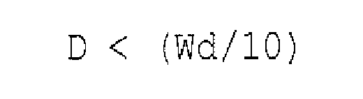
where D is a distance between the axis centers of each of the image carrier and the corresponding bias applying roller in a moving direction of the endless belt and Wd is a distance between centers of the image carriers. - The image forming apparatus according to Claim 1, wherein the endless belt has a surface resistivity within a range from 9.5 logΩ/square to 12.0 logΩ/square.
- The image forming apparatus according to Claim 5, wherein the endless belt has an amount of surface resistivity change not greater than 0.5 logΩ/square, from 10 seconds to five hours after the endless belt starts to receive a voltage of 500 V.
- The image forming apparatus according to Claim 1., further comprising a positioner configured to position the bias applying roller to contact the endless belt.
- The image forming apparatus according to Claim 1, wherein the endless belt is a single-layered belt including polyimide or polyamide-imide resin.
- The image forming apparatus according to Claim 8, wherein the endless belt has a thickness within a range from 40 µm to 100 µm.
- The image forming apparatus according to Claim 1, wherein the binder resin is a polyester resin.
- An image forming method, comprising;
applying a transfer bias with a bias applying roller to a back surface of an endless belt whose front surface contacts an image carrier to form a transfer nip, to transfer a toner image from the image carrier to the endless belt;
forming of a toner having an additive burial rate of not less than 40 percent, wherein the toner includes,
a mother particle including a binder resin and a colorant, and
an external additive, and
locating the bias applying roller so as to satisfy the following relationship
where A is a diameter of the image carrier, B is a diameter of the bias applying roller, C is a thickness of the endless belt, and L is a distance between axis centers of the image carrier and the bias applying roller, on a virtual plane perpendicular to an axis direction of the image carrier. - A computer readable storage medium including computer executable instructions, wherein the instructions, when executed by a processor, cause the processor to perform a method comprising:applying a transfer bias with a bias applying roller to a back surface of an endless belt whose front surface contacts an image carrier to form a transfer nip, to transfer a toner image from the image carrier to the endless belt;forming of a toner having an additive burial rate of not less than 40 percent, wherein the toner includes,
a mother particle including a binder resin and a colorant, and
an external additive, andlocating the bias applying roller so as to satisfy the following relationshipwhere A is a diameter of the image carrier, B is a diameter of the bias applying roller, C is a thickness of the endless belt, and L is a distance between axis centers of the image carrier and the bias applying roller, on a virtual plane perpendicular to an axis direction of the image carrier.
Applications Claiming Priority (1)
| Application Number | Priority Date | Filing Date | Title |
|---|---|---|---|
| JP2006136894A JP4724601B2 (en) | 2006-05-16 | 2006-05-16 | Image forming apparatus and image forming method |
Publications (2)
| Publication Number | Publication Date |
|---|---|
| EP1857888A1 true EP1857888A1 (en) | 2007-11-21 |
| EP1857888B1 EP1857888B1 (en) | 2018-01-17 |
Family
ID=38355552
Family Applications (1)
| Application Number | Title | Priority Date | Filing Date |
|---|---|---|---|
| EP07108265.5A Ceased EP1857888B1 (en) | 2006-05-16 | 2007-05-15 | Image forming apparatus |
Country Status (3)
| Country | Link |
|---|---|
| US (1) | US7860438B2 (en) |
| EP (1) | EP1857888B1 (en) |
| JP (1) | JP4724601B2 (en) |
Cited By (3)
| Publication number | Priority date | Publication date | Assignee | Title |
|---|---|---|---|---|
| EP2088474A3 (en) * | 2008-02-06 | 2009-09-23 | Ricoh Company, Ltd. | Image forming apparatus and image forming method |
| US8270885B2 (en) | 2007-07-10 | 2012-09-18 | Ricoh Company, Limited | Image forming apparatus utilizing plural pressers of different weights and image forming method forming an image with the image forming apparatus |
| US8301064B2 (en) | 2008-02-06 | 2012-10-30 | Ricoh Company, Limited | Image forming apparatus including pressers configured to press a receptor to image bearers downward in the vertical direction |
Families Citing this family (12)
| Publication number | Priority date | Publication date | Assignee | Title |
|---|---|---|---|---|
| JP2009020154A (en) * | 2007-07-10 | 2009-01-29 | Konica Minolta Business Technologies Inc | Electrophotographic transfer belt |
| JP4812728B2 (en) | 2007-10-16 | 2011-11-09 | シャープ株式会社 | Image forming apparatus |
| US7711298B2 (en) * | 2007-11-28 | 2010-05-04 | Lexmark International, Inc. | Methods and devices to transfer toner in an image forming device to control charge buildup on a toner image |
| JP2009139657A (en) | 2007-12-06 | 2009-06-25 | Ricoh Co Ltd | Belt member, transfer device, image forming apparatus, and belt member specification determination evaluation method |
| JP5142037B2 (en) * | 2008-07-24 | 2013-02-13 | 株式会社リコー | Belt member, transfer device, and image forming apparatus |
| JP5473321B2 (en) * | 2008-12-27 | 2014-04-16 | キヤノン株式会社 | Image forming apparatus and image forming apparatus control method |
| JP5267942B2 (en) * | 2009-03-17 | 2013-08-21 | 株式会社リコー | Image forming apparatus |
| JP5014455B2 (en) * | 2010-04-12 | 2012-08-29 | シャープ株式会社 | Transfer device and image forming apparatus |
| JP2012008514A (en) | 2010-05-24 | 2012-01-12 | Casio Electronics Co Ltd | Image forming apparatus |
| JP6191488B2 (en) * | 2014-02-05 | 2017-09-06 | 富士ゼロックス株式会社 | Image forming apparatus |
| JP2018010175A (en) * | 2016-07-14 | 2018-01-18 | 富士ゼロックス株式会社 | Image forming apparatus |
| JP2024166677A (en) | 2023-05-19 | 2024-11-29 | 京セラドキュメントソリューションズ株式会社 | Image forming device |
Citations (3)
| Publication number | Priority date | Publication date | Assignee | Title |
|---|---|---|---|---|
| EP1351100A1 (en) * | 2001-01-12 | 2003-10-08 | Fuji Xerox Co., Ltd. | Image forming device and method |
| EP1380900A1 (en) * | 2002-07-10 | 2004-01-14 | Ricoh Company, Ltd. | Developer for developing electrostatic image, image forming apparatus and image forming method |
| US20050013636A1 (en) * | 2003-07-02 | 2005-01-20 | Yuuji Sawai | Method for evaluating changes in resistance of electric resistance member and image forming apparatus using same |
Family Cites Families (31)
| Publication number | Priority date | Publication date | Assignee | Title |
|---|---|---|---|---|
| JPH03100661A (en) | 1989-09-14 | 1991-04-25 | Konica Corp | Image forming method |
| JP3328013B2 (en) | 1993-07-08 | 2002-09-24 | コニカ株式会社 | Electrostatic image developer and multicolor image forming method |
| JPH07152202A (en) | 1993-11-29 | 1995-06-16 | Hitachi Chem Co Ltd | Electrostatic charge developing toner, its production and developer |
| JP3516551B2 (en) * | 1995-05-11 | 2004-04-05 | 株式会社リコー | Electrostatic image forming device |
| JPH09319134A (en) | 1996-05-29 | 1997-12-12 | Konica Corp | Static-charge-image development toner and multicolor image forming method |
| JP3019781B2 (en) | 1996-09-06 | 2000-03-13 | 富士ゼロックス株式会社 | Image forming apparatus, intermediate transfer belt, and method of manufacturing the same |
| JP3056122B2 (en) | 1997-05-09 | 2000-06-26 | 花王株式会社 | Full color toner for non-magnetic one component |
| JPH1138796A (en) * | 1997-07-15 | 1999-02-12 | Toshiba Corp | Image forming device |
| JP3762078B2 (en) | 1997-11-17 | 2006-03-29 | 三洋化成工業株式会社 | Dry toner and its production method |
| JPH11184275A (en) | 1997-12-18 | 1999-07-09 | Ricoh Co Ltd | Image forming device |
| JP4038328B2 (en) * | 1999-10-29 | 2008-01-23 | 株式会社リコー | Image forming apparatus, transfer material conveying method, and transfer apparatus |
| JP2001265135A (en) | 2000-03-14 | 2001-09-28 | Canon Inc | Image forming device |
| JP2001305888A (en) | 2000-04-24 | 2001-11-02 | Ricoh Co Ltd | Transfer device and image forming device |
| JP2001331046A (en) | 2000-05-18 | 2001-11-30 | Ricoh Co Ltd | Image forming device |
| JP3963638B2 (en) * | 2000-09-07 | 2007-08-22 | 株式会社リコー | Image forming apparatus |
| US6611672B2 (en) * | 2000-09-26 | 2003-08-26 | Ricoh Company, Ltd. | Image forming apparatus, monocolor image forming apparatus, toner recycling apparatus and intermediate transfer member |
| JP3625433B2 (en) * | 2001-04-27 | 2005-03-02 | キヤノン株式会社 | Granular structure and manufacturing method thereof |
| JP2002341615A (en) | 2001-05-15 | 2002-11-29 | Ricoh Co Ltd | Color image forming device and method for forming color image |
| EP1271259B1 (en) * | 2001-06-26 | 2013-11-20 | Ricoh Company, Ltd. | Image forming apparatus and process cartridge therefor |
| JP2003029550A (en) * | 2001-07-13 | 2003-01-31 | Ricoh Co Ltd | Image forming device |
| JP2003029541A (en) * | 2001-07-13 | 2003-01-31 | Ricoh Co Ltd | Image forming device |
| JP4004020B2 (en) * | 2001-07-23 | 2007-11-07 | 株式会社リコー | Bias application method, bias application device, and image forming apparatus |
| JP2003131497A (en) * | 2001-10-29 | 2003-05-09 | Ricoh Co Ltd | Transfer device and image forming apparatus using the same |
| JP2003202729A (en) * | 2001-12-28 | 2003-07-18 | Sharp Corp | Color image forming equipment |
| JP2003255769A (en) * | 2002-02-28 | 2003-09-10 | Ricoh Co Ltd | Image forming device |
| US6901234B2 (en) * | 2002-03-18 | 2005-05-31 | Ricoh Company, Ltd. | Image forming apparatus including an intermediate image transfer belt and high resistance contact member |
| US6934484B2 (en) * | 2002-08-01 | 2005-08-23 | Ricoh Company, Ltd. | Image-forming apparatus and image-forming method |
| US7174124B2 (en) * | 2002-09-13 | 2007-02-06 | Ricoh Company, Ltd. | Tandem color image forming apparatus with an image transfer belt and backup roller |
| EP1424608B1 (en) * | 2002-11-05 | 2015-07-22 | Ricoh Company, Ltd. | Colour image forming apparatus |
| US7502583B2 (en) * | 2004-09-10 | 2009-03-10 | Ricoh Company, Limited | Transfer device and image forming apparatus for enhancement of an image stored on a recording medium |
| JP5020516B2 (en) * | 2006-01-30 | 2012-09-05 | 株式会社リコー | Transfer device and image forming apparatus having the same |
-
2006
- 2006-05-16 JP JP2006136894A patent/JP4724601B2/en not_active Expired - Fee Related
-
2007
- 2007-05-15 US US11/748,511 patent/US7860438B2/en not_active Expired - Fee Related
- 2007-05-15 EP EP07108265.5A patent/EP1857888B1/en not_active Ceased
Patent Citations (3)
| Publication number | Priority date | Publication date | Assignee | Title |
|---|---|---|---|---|
| EP1351100A1 (en) * | 2001-01-12 | 2003-10-08 | Fuji Xerox Co., Ltd. | Image forming device and method |
| EP1380900A1 (en) * | 2002-07-10 | 2004-01-14 | Ricoh Company, Ltd. | Developer for developing electrostatic image, image forming apparatus and image forming method |
| US20050013636A1 (en) * | 2003-07-02 | 2005-01-20 | Yuuji Sawai | Method for evaluating changes in resistance of electric resistance member and image forming apparatus using same |
Cited By (3)
| Publication number | Priority date | Publication date | Assignee | Title |
|---|---|---|---|---|
| US8270885B2 (en) | 2007-07-10 | 2012-09-18 | Ricoh Company, Limited | Image forming apparatus utilizing plural pressers of different weights and image forming method forming an image with the image forming apparatus |
| EP2088474A3 (en) * | 2008-02-06 | 2009-09-23 | Ricoh Company, Ltd. | Image forming apparatus and image forming method |
| US8301064B2 (en) | 2008-02-06 | 2012-10-30 | Ricoh Company, Limited | Image forming apparatus including pressers configured to press a receptor to image bearers downward in the vertical direction |
Also Published As
| Publication number | Publication date |
|---|---|
| US7860438B2 (en) | 2010-12-28 |
| JP2007310024A (en) | 2007-11-29 |
| JP4724601B2 (en) | 2011-07-13 |
| US20070269241A1 (en) | 2007-11-22 |
| EP1857888B1 (en) | 2018-01-17 |
Similar Documents
| Publication | Publication Date | Title |
|---|---|---|
| EP1857888B1 (en) | Image forming apparatus | |
| US7639976B2 (en) | Image forming apparatus | |
| US8592113B2 (en) | Toner, method of manufacturing toner, developer, and image forming method | |
| US8871417B2 (en) | Toner, image forming apparatus, and process cartridge | |
| US11340540B2 (en) | Image forming apparatus and image forming method | |
| JP2010085969A (en) | Toner for electrostatic latent image development and method for manufacturing the same, and electrostatic latent image developer using the toner, toner container and image forming apparatus, process cartridge, and method for forming image | |
| US8270885B2 (en) | Image forming apparatus utilizing plural pressers of different weights and image forming method forming an image with the image forming apparatus | |
| US8778583B2 (en) | Toner, developer, image forming apparatus, and process cartridge | |
| US8301064B2 (en) | Image forming apparatus including pressers configured to press a receptor to image bearers downward in the vertical direction | |
| US8389186B2 (en) | Toner set, developer set, image forming apparatus, and image forming method | |
| JP2007304316A (en) | Image forming apparatus and forced toner consumption method | |
| US9069269B2 (en) | Toner for electrostatic latent image development and method of producing toner for electrostatic latent image development | |
| EP2088474A2 (en) | Image forming apparatus and image forming method | |
| JP2008090185A (en) | Cleaning device and image forming apparatus | |
| JP4974539B2 (en) | Non-magnetic one-component development system and development device | |
| US9726993B2 (en) | Electrostatic charge image developing toner, electrostatic charge image developer, and toner cartridge | |
| JP5504822B2 (en) | Electrophotographic carrier, electrophotographic developer, image forming method, image forming apparatus, process cartridge, and container containing electrophotographic developer | |
| US10180650B2 (en) | Image forming apparatus | |
| US9874836B1 (en) | Image forming apparatus using a developer containing a specific toner | |
| JP4943243B2 (en) | Electrophotographic developing carrier, carrier manufacturing method, developer, and image forming method | |
| JP2006259529A (en) | Image forming method and image forming apparatus using the method | |
| JP2004109504A (en) | Color image forming method and image forming apparatus | |
| JP2007047738A (en) | Image forming apparatus and image forming method | |
| JP2004145199A (en) | Image forming method and apparatus | |
| JPH08297446A (en) | Image forming method |
Legal Events
| Date | Code | Title | Description |
|---|---|---|---|
| PUAI | Public reference made under article 153(3) epc to a published international application that has entered the european phase |
Free format text: ORIGINAL CODE: 0009012 |
|
| AK | Designated contracting states |
Kind code of ref document: A1 Designated state(s): AT BE BG CH CY CZ DE DK EE ES FI FR GB GR HU IE IS IT LI LT LU LV MC MT NL PL PT RO SE SI SK TR |
|
| AX | Request for extension of the european patent |
Extension state: AL BA HR MK YU |
|
| 17P | Request for examination filed |
Effective date: 20080226 |
|
| AKX | Designation fees paid |
Designated state(s): DE FR GB |
|
| 17Q | First examination report despatched |
Effective date: 20161114 |
|
| GRAP | Despatch of communication of intention to grant a patent |
Free format text: ORIGINAL CODE: EPIDOSNIGR1 |
|
| INTG | Intention to grant announced |
Effective date: 20170413 |
|
| GRAS | Grant fee paid |
Free format text: ORIGINAL CODE: EPIDOSNIGR3 |
|
| GRAJ | Information related to disapproval of communication of intention to grant by the applicant or resumption of examination proceedings by the epo deleted |
Free format text: ORIGINAL CODE: EPIDOSDIGR1 |
|
| GRAL | Information related to payment of fee for publishing/printing deleted |
Free format text: ORIGINAL CODE: EPIDOSDIGR3 |
|
| GRAP | Despatch of communication of intention to grant a patent |
Free format text: ORIGINAL CODE: EPIDOSNIGR1 |
|
| INTC | Intention to grant announced (deleted) | ||
| INTG | Intention to grant announced |
Effective date: 20170913 |
|
| GRAA | (expected) grant |
Free format text: ORIGINAL CODE: 0009210 |
|
| AK | Designated contracting states |
Kind code of ref document: B1 Designated state(s): DE FR GB |
|
| REG | Reference to a national code |
Ref country code: GB Ref legal event code: FG4D |
|
| REG | Reference to a national code |
Ref country code: DE Ref legal event code: R096 Ref document number: 602007053744 Country of ref document: DE |
|
| REG | Reference to a national code |
Ref country code: FR Ref legal event code: PLFP Year of fee payment: 12 |
|
| REG | Reference to a national code |
Ref country code: DE Ref legal event code: R097 Ref document number: 602007053744 Country of ref document: DE |
|
| PLBE | No opposition filed within time limit |
Free format text: ORIGINAL CODE: 0009261 |
|
| STAA | Information on the status of an ep patent application or granted ep patent |
Free format text: STATUS: NO OPPOSITION FILED WITHIN TIME LIMIT |
|
| 26N | No opposition filed |
Effective date: 20181018 |
|
| PGFP | Annual fee paid to national office [announced via postgrant information from national office to epo] |
Ref country code: DE Payment date: 20200520 Year of fee payment: 14 Ref country code: FR Payment date: 20200522 Year of fee payment: 14 |
|
| PGFP | Annual fee paid to national office [announced via postgrant information from national office to epo] |
Ref country code: GB Payment date: 20200527 Year of fee payment: 14 |
|
| REG | Reference to a national code |
Ref country code: DE Ref legal event code: R119 Ref document number: 602007053744 Country of ref document: DE |
|
| GBPC | Gb: european patent ceased through non-payment of renewal fee |
Effective date: 20210515 |
|
| PG25 | Lapsed in a contracting state [announced via postgrant information from national office to epo] |
Ref country code: GB Free format text: LAPSE BECAUSE OF NON-PAYMENT OF DUE FEES Effective date: 20210515 Ref country code: DE Free format text: LAPSE BECAUSE OF NON-PAYMENT OF DUE FEES Effective date: 20211201 |
|
| PG25 | Lapsed in a contracting state [announced via postgrant information from national office to epo] |
Ref country code: FR Free format text: LAPSE BECAUSE OF NON-PAYMENT OF DUE FEES Effective date: 20210531 |