JP4038328B2 - Image forming apparatus, transfer material conveying method, and transfer apparatus - Google Patents
Image forming apparatus, transfer material conveying method, and transfer apparatus Download PDFInfo
- Publication number
- JP4038328B2 JP4038328B2 JP2000249856A JP2000249856A JP4038328B2 JP 4038328 B2 JP4038328 B2 JP 4038328B2 JP 2000249856 A JP2000249856 A JP 2000249856A JP 2000249856 A JP2000249856 A JP 2000249856A JP 4038328 B2 JP4038328 B2 JP 4038328B2
- Authority
- JP
- Japan
- Prior art keywords
- transfer
- transfer material
- guide member
- nip
- image carrier
- Prior art date
- Legal status (The legal status is an assumption and is not a legal conclusion. Google has not performed a legal analysis and makes no representation as to the accuracy of the status listed.)
- Expired - Lifetime
Links
Images


Classifications
-
- G—PHYSICS
- G03—PHOTOGRAPHY; CINEMATOGRAPHY; ANALOGOUS TECHNIQUES USING WAVES OTHER THAN OPTICAL WAVES; ELECTROGRAPHY; HOLOGRAPHY
- G03G—ELECTROGRAPHY; ELECTROPHOTOGRAPHY; MAGNETOGRAPHY
- G03G15/00—Apparatus for electrographic processes using a charge pattern
- G03G15/65—Apparatus which relate to the handling of copy material
- G03G15/6555—Handling of sheet copy material taking place in a specific part of the copy material feeding path
- G03G15/6558—Feeding path after the copy sheet preparation and up to the transfer point, e.g. registering; Deskewing; Correct timing of sheet feeding to the transfer point
-
- G—PHYSICS
- G03—PHOTOGRAPHY; CINEMATOGRAPHY; ANALOGOUS TECHNIQUES USING WAVES OTHER THAN OPTICAL WAVES; ELECTROGRAPHY; HOLOGRAPHY
- G03G—ELECTROGRAPHY; ELECTROPHOTOGRAPHY; MAGNETOGRAPHY
- G03G15/00—Apparatus for electrographic processes using a charge pattern
- G03G15/14—Apparatus for electrographic processes using a charge pattern for transferring a pattern to a second base
- G03G15/16—Apparatus for electrographic processes using a charge pattern for transferring a pattern to a second base of a toner pattern, e.g. a powder pattern, e.g. magnetic transfer
- G03G15/1665—Apparatus for electrographic processes using a charge pattern for transferring a pattern to a second base of a toner pattern, e.g. a powder pattern, e.g. magnetic transfer by introducing the second base in the nip formed by the recording member and at least one transfer member, e.g. in combination with bias or heat
- G03G15/167—Apparatus for electrographic processes using a charge pattern for transferring a pattern to a second base of a toner pattern, e.g. a powder pattern, e.g. magnetic transfer by introducing the second base in the nip formed by the recording member and at least one transfer member, e.g. in combination with bias or heat at least one of the recording member or the transfer member being rotatable during the transfer
-
- G—PHYSICS
- G03—PHOTOGRAPHY; CINEMATOGRAPHY; ANALOGOUS TECHNIQUES USING WAVES OTHER THAN OPTICAL WAVES; ELECTROGRAPHY; HOLOGRAPHY
- G03G—ELECTROGRAPHY; ELECTROPHOTOGRAPHY; MAGNETOGRAPHY
- G03G15/00—Apparatus for electrographic processes using a charge pattern
- G03G15/14—Apparatus for electrographic processes using a charge pattern for transferring a pattern to a second base
- G03G15/16—Apparatus for electrographic processes using a charge pattern for transferring a pattern to a second base of a toner pattern, e.g. a powder pattern, e.g. magnetic transfer
- G03G15/1665—Apparatus for electrographic processes using a charge pattern for transferring a pattern to a second base of a toner pattern, e.g. a powder pattern, e.g. magnetic transfer by introducing the second base in the nip formed by the recording member and at least one transfer member, e.g. in combination with bias or heat
-
- G—PHYSICS
- G03—PHOTOGRAPHY; CINEMATOGRAPHY; ANALOGOUS TECHNIQUES USING WAVES OTHER THAN OPTICAL WAVES; ELECTROGRAPHY; HOLOGRAPHY
- G03G—ELECTROGRAPHY; ELECTROPHOTOGRAPHY; MAGNETOGRAPHY
- G03G2215/00—Apparatus for electrophotographic processes
- G03G2215/00362—Apparatus for electrophotographic processes relating to the copy medium handling
- G03G2215/00367—The feeding path segment where particular handling of the copy medium occurs, segments being adjacent and non-overlapping. Each segment is identified by the most downstream point in the segment, so that for instance the segment labelled "Fixing device" is referring to the path between the "Transfer device" and the "Fixing device"
- G03G2215/00409—Transfer device
Description
【0001】
【発明の属する技術分野】
本発明は、複写機、ファクシミリ、プリンター等の画像形成装置、中間転写体上の着色画像を転写材上に転写するための転写装置、像担持体上の着色画像を転写材上に転写する転写領域へ転写材を搬送するための転写材搬送方法に関するものである。
【0002】
【従来の技術】
この種の画像形成装置としては、像担持体上に静電的に担持された着色画像を転写材に転写させるために、その像担持体に対して弾性転写部材を当接させることで転写領域である転写ニップを形成し、この転写ニップに転写バイアスを印加することで転写材上に像担持体上の着色画像を転写するものが知られている。転写ニップを形成する像担持体と弾性転写部材との間には、転写材搬送方向上流側及び下流側において空隙部が形成される。このような画像形成装置では、転写時に印加される転写バイアスによって、上記空隙部においても電界が形成されることになる。
【0003】
【発明が解決しようとする課題】
転写材搬送方向上流側の空隙部に転写材が介在している場合、その転写材が像担持体から離れた状態にあると、その空隙部に形成される電界によって像担持体上の着色画像が飛翔転写され、いわゆるプレ転写が起きる。以下、この転写領域の転写材搬送方向上流側でプレ転写が発生し得る領域をプレ転写領域という。このプレ転写が起きると、正規画像のまわりにトナーが散ってしまい、いわゆる転写チリが発生するという問題があった。この問題は、転写材を転写面の反対側から像担持体側に押し当てて転写ニップを形成して転写を行う画像形成装置に限らず、転写材の転写面が像担持体に接触した状態で転写を行う画像形成装置であれば、例えば、転写材に対して転写面の反対側から転写チャージャにより電荷を付与し、転写電界を形成して転写を行うような画像形成装置においても、同様に起こり得る。
【0004】
特に、感光体に形成した着色画像であるトナー像を、一旦、中間転写体に1次転写し、中間転写体に密着させるように搬送されてきた転写材上へトナー像を転写する2次転写方式を採用したフルカラー複写機等の画像形成装置では、上記転写チリが、転写材上の画像に、その散ったトナーによるニジミ現象として表れる。
【0005】
上記プレ転写領域において転写材が像担持体から離れてしまうのは、以下の2つの理由によるものと考えられる。
【0006】
第1の理由は、転写領域における像担持体の曲率に関係する。
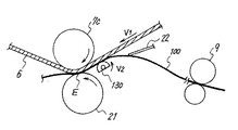
図7は、中間転写ユニットを備えた従来のフルカラー画像形成装置における2次転写領域周辺の概略構成図である。この画像形成装置では、転写性を良くするために、中間転写ベルト6と転写ローラ21により、転写ニップEが形成されている。図示しないレジストローラによって搬送されてきた転写材である記録紙100は、ガイド部材22に沿って進行し、まず、その先端が像担持体である中間転写ベルト6の平坦部6aに接触する。その後、中間転写ベルト6に沿って転写ニップEに向かって搬送され、転写ニップEに進入する。このように記録紙100を搬送することで、その記録紙100は、転写材搬送方向上流側において緩やかに図中上方に湾曲する。この湾曲により、記録紙100を、中間転写ベルト6の表面に密着するように、ベルト表面に近づけることができる。
【0007】
ところが、中間転写ベルト6は、図7に示すように、転写ニップE付近で弾性転写部材である転写ローラ21に対向して配置された対向ローラ7cによって湾曲された状態にある。この状態においては、中間転写ベルト6の湾曲部6bで記録紙100と中間転写ベルト6との密着性(以下、単に「密着性」という。)を維持するためには、その湾曲部6bに沿って記録紙100も湾曲状態にならなければならない。しかし、記録紙100の湾曲部分には、そのコシにより、中間転写ベルト6の平坦部6aを延長した方向に復元しようとする復元力が働く。また、この記録紙100が転写ニップEに挟持された状態にあるとき、記録紙100の湾曲部分には、そのコシにより、転写ニップEの転写材搬送方向上流端部(以下、「転写ニップ入口」という。)における中間転写ベルト6と転写ローラ21の共通接線方向に、復元しようとする復元力も働く。このため、転写ニップ入口付近の記録紙100部分は、中間転写ベルト6から離れる方向に力を受けることになる。
【0008】
また、通常では、転写ニップEにおける転写材搬送速度よりもレジストローラによる転写剤搬送速度の方が速く設定されている。このため、転写ニップEの転写材搬送方向上流側で記録紙100を緩やかに図中上方に湾曲させながら搬送する場合、記録紙100に上記復元力が働くと、転写ニップEで挟持された状態の記録紙100は、図7に示すように、転写ニップ入口付近で記録紙100が撓んだ状態となり、全体が緩やかなS字状になる。このため、記録紙100は、必ずしもベルト面形状に一致せず、転写ニップEの直前部分すなわちプレ転写領域Fにおいて、中間転写ベルト6と記録紙100との間に微少な空隙部Gを生じる。よって、記録紙100は、プレ転写領域Fにおいて中間転写ベルト6から離れることになる。特に、上記対抗ローラ7cが転写ローラ21に対して鉛直方向上方に配置されているような場合には、重力も影響して記録紙100が中間転写ベルト6から更に離れやすくなる。
【0009】
第2の理由は、転写材を転写ニップに案内するガイド部材のガイドの仕方に関係する。
図8は、図7に示した画像形成装置におけるガイド部材である第1及び第2ガイド部材22,23の配置を示す説明図である。第1ガイド部材22の転写材搬送方向下流端部(以下、単に「下流端部」という。)22aは、転写ニップ入口と第2ガイド部材23の下流端部23aとを結んだ基準線D(図中破線)に対して、中間転写ベルト6側に位置決めされている。このような配置条件では、これらガイド部材22,23の間を記録紙100が比較的自由な経路で通過し、転写ニップEに向かって進行することができる。すなわち、これらガイド部材22,23間を通過させて記録紙100を転写ニップEまで搬送しようとするとき、その記録紙の厚さ、カールの状況、レジストローラ9と転写ローラ21による搬送速度差などによって、例えば図中の実線及び一点破線で示すように記録紙100の転写ニップEへの進入形状が異なってくる。
【0010】
具体的に説明すると、記録紙100が普通紙のようにコシの弱いものである場合、その記録紙100は、図中実線で示すように、第1ガイド部材22に沿って進行していき、第2ガイド部材23の端部23aを擦るようにして転写ニップEに向かって進行する。そして、この記録紙100は転写ニップEにほぼ直接的に進入することになる。この進入の際、記録紙100は、中間転写ベルト6あるいは転写ローラ21のいずれかに先に接触してから転写ニップに進入することになる。このとき、記録紙100が先に転写ローラ21に接触してから転写ニップEに進入した場合には、その記録紙100はプレ転写領域Fにおいて中間転写ベルト6から離れた状態となる。ここで、転写ニップに進入する際に先にどちらに接触するかは、その記録紙の厚さやカールの状況などの微妙な違いで決まる。このため、記録紙100が先に転写ローラ21に接触してから転写ニップEに進入し、上述のようにプレ転写領域Fにおいて記録紙100が中間転写ベルト6から離れてしまう可能性は非常に高くなる。
【0011】
一方、記録紙100が厚紙のようにコシが強いものである場合、その記録紙100は、図中一点破線で示すように、中間転写ベルト6の平坦部6aに沿って転写ニツプEに進入する。この場合、上記第1の理由で述べたように、転写ニップ入口付近の記録紙100の撓みが発生する。特に、記録紙100の先端が平坦部6aに接触する位置と転写ニップE入口との距離が離れていればいるほど、その撓み具合は大きいものとなる。この撓みは、レジストローラ9と転写ニップEの間の部分で発生することになるが、その撓みがプレ転写領域Fで起きるおそれもあり、プレ転写領域Fにおいて記録紙100が中間転写ベルト6から離れてしまう可能性がある。
【0012】
なお、上述した2つの理由は、像担持体がドラム形状等である場合も同様である。
【0013】
ところで、特開平6−3974号公報には、プレ転写領域で発生する転写チリを防止するための構成を有する画像形成装置が開示されている。この画像形成装置も、上述した図7及び図8に示す従来装置と同様に、像担持体上のトナー像を転写材へ静電的に転写するための転写部材を有し、その転写部材と像担持体との接触部に転写ニップを形成して転写を行う。この画像形成装置は、転写位置へ転写材を案内する第1及び第2ガイド部材に相当する上下ガイド部材の転写材搬送方向最下流側の端部が、転写ニップのうち転写材搬送方向の最上流側の点における像担持体の接線上あるいはこの接線よりも上方に位置する構成となっている。しかも、これら上下ガイド部材の転写材案内面と水平方向とのなす角度が上記接線と水平方向とのなす角度よりも小さく設定されている。このような条件を満たすように上下ガイド部材を配置することで、転写材を像担持体に密着させたまま転写ニップに進入させることができ、プレ転写領域では像担持体と転写材との間に空隙部がなくなり、プレ転写を防止することができるとしている。
【0014】
この画像形成装置では、上記条件を満たすことで、上下ガイド部材によって案内された転写材を像担持体に接触させてから転写ニップに進入させることができるとしている。そのため、転写材が転写ニップに直接的に進入するようなことはない。しかし、転写材のコシの強さの違いによって、その転写材先端と像担持体との接触位置が異なってくることはある。
【0015】
上記第2の理由で説明したように、この接触位置と転写ニップ入口との距離が離れすぎると、レジストローラと転写部材との搬送速度差による転写材の撓みの具合が大きくなるが、この画像形成装置においても、同様に、その撓みがプレ転写領域Fで起きるおそれがある。したがって、プレ転写領域Fにおいて記録紙100が中間転写ベルト6から離れてしまう可能性がある。
【0016】
本発明は、以上の問題点に鑑みなされたものであり、その目的とするところは、プレ転写領域における像担持体と転写材との密着性を維持することでプレ転写を防止し、転写チリのない画像を形成することができる画像形成装置、転写材搬送方法及び転写装置を提供することである。
【0017】
【課題を解決するための手段】
上記目的を達成するために、請求項1の発明は、着色画像を担持する像担持体と、該着色画像を転写材に転写させるために該像担持体に対して当接して転写ニップを形成し、該転写ニップに搬送されてくる該転写材を該像担持体に接触させてから該転写ニップに進入させ、該像担持体から該転写材に該着色画像を静電的に転写させる弾性転写部材とを備えた画像形成装置において、上記転写ニップに進入する上記転写材を転写面側から案内する第1ガイド部材と、上記転写ニップに進入する上記転写材を転写面の反対側から案内する第2ガイド部材とを備え、上記転写材を案内するときに該転写材の搬送方向両端以外が接触する部分の中で転写材搬送方向最下流に位置する上記第1ガイド部材の規制箇所が、該規制箇所よりも転写材搬送方向下流側に位置し、該転写材を案内するときに該転写材の搬送方向両端以外が接触する部分の中で転写材搬送方向最下流に位置する上記第2ガイド部材の規制箇所と、上記転写ニップの転写材搬送方向上流端部とを結ぶ基準線よりも、上記像担持体側から離れる位置となるように、上記第1ガイド部材及び上記第2ガイド部材を配置し、上記第1ガイド部材の規制箇所を含む転写材搬送方向上流側部分が変位しないように構成したことを特徴とするものである。
【0018】
この画像形成装置においては、転写材を、第1ガイド部材の規制箇所と、該規制箇所よりも転写材搬送方向下流側に位置する第2ガイド部材の規制箇所とで規制しながら、転写ニップに向けて搬送する。この搬送中、第1ガイド部材の転写材の搬送方向両端以外が接触する部分の中で転写材搬送方向最下流に位置する規制箇所は、転写材の搬送方向両端以外が接触する部分の中で転写材搬送方向最下流に位置する第2ガイド部材の規制箇所と転写ニップの転写材搬送方向上流端部である転写ニップ入口とを結ぶ基準線よりも上記像担持体側から離れる位置となっている。このため、転写材が転写ニップに進入したとき、第2ガイド部材の規制箇所に接触した転写材部分よりも転写材搬送方向上流側部分は、第1ガイド部材の規制箇所により、像担持体から離れる方向に押し出されるように規制される。言い換えれば、転写ニップ入口と第1ガイド部材の規制箇所との間に位置する転写材部分は、第2ガイド部材の規制箇所により像担持体側に押し出される。このような構成により、転写ニップの転写材搬送方向上流側における転写材部分を、像担持体側に向かって凸状になるように強制的に湾曲させることができる。よって、プレ転写領域に位置する転写材部分を像担持体に押し付けることができる。このように押し付けることで、像担持体の曲率、重力による転写材の撓みや、転写材を像担持体から離そうとする力を抑え込むことができ、プレ転写領域における密着性を維持することができる。
【0019】
また、このように転写材を強制的に湾曲させることで、転写ニップにおける転写材搬送速度よりもレジストローラによる転写材搬送速度の方が速く設定されていても、転写材はその湾曲部分では撓みにくくなる。よって、その撓みはレジストローラの出口付近で発生することになる。したがって、転写材の種類に関係なく、プレ転写領域における密着性を維持することができる。
また、転写材の種類によらずに安定した転写性を得るためには、どんな種類の転写材であっても、転写ニップへの進入形状すなわち転写材の湾曲度合いがほぼ同じであるのが好ましい。しかし、第1ガイド部材の規制箇所が変化すると、転写材の湾曲度合いがコシの強さによって異なる結果となり、転写紙の種類によって転写性が変化してしまう。そこで、請求項1の画像形成装置では、第1ガイド部材の規制箇所を含む転写材搬送方向上流側部分が変位しないように構成した。この構成によれば、湾曲した転写材の復元力を受けても、第1ガイド部材の規制箇所は変位しない。よって、コシの強さが異なる転写材を搬送する場合であっても、ほぼ同じ搬送経路を辿って転写ニップに進入させることができる。
【0020】
また、請求項2の発明は、請求項1の画像形成装置において、上記転写材の後端が上記第1ガイド部材から離れるときに、該第1ガイド部材における該転写材の後端が離れる開放箇所が、上記基準線近傍に位置するように、該開放箇所を変位可能に構成したことを特徴とするものである。
【0021】
上記請求項1の画像形成装置のようにして転写材を湾曲させる場合、転写材の後端は、上記第1ガイド部材の規制箇所に到達した後、そこから転写材搬送方向下流側に向かって第1ガイド部材の搬送面に当接しながら移動する。このとき、転写材後端が転写ニップ入口と第2ガイド部材の規制箇所とを結ぶ基準線に達する前に上記第1ガイド部材から離れると、転写材のコシによる復元力で転写材が振動することになる。このように転写材が振動すると、その振動が転写ニップにまで伝わってプレ転写領域の密着性が不安定となる。この結果、プレ転写が発生し、更には転写ニップにおける転写性にも影響を与えることとなる。
この転写材の振動は、転写材の後端が基準線近傍で第1ガイド部材から離れるようにすれば抑制することができる。この観点から、第1ガイド部材の転写材搬送方向下流側先端を上記基準線付近に近づけることで転写材後端を基準線付近で離すようにした場合、第1ガイド部材の先端は像担持体に近づくことになる。このため、像担持体上のトナーが第1ガイド部材に付着してトナー汚れを起こし、そのトナー汚れが転写材を汚してしまうおそれがある。更に、この第1ガイド部材が金属材料で形成されている場合には、像担持体上のトナー画像を乱すおそれもある。これは、特にフルカラー画像において顕著である。
【0022】
そこで、請求項2の画像形成装置では、転写材の後端が第1ガイド部材から離れる開放箇所が上記基準線近傍に位置するように、第1ガイド部材の開放箇所を変位可能に構成した。この構成によれば、転写材の後端は、第1ガイド部材から離れるとき、上記基準線近傍に位置することになる。したがって、その開放時の復元力は非常に小さく、その振動を抑制することができる。また、この画像形成装置では、開放箇所を転写材後端が第1ガイド部材から離れるときだけ上述のように変位させるので、その変位により第1ガイド部材が像担持体に近づくような場合でも、上述したトナー汚れや像担持体上のトナー画像を乱すなどの不具合は軽減される。
【0023】
また、請求項3の発明は、請求項2の画像形成装置において、上記第1ガイド部材の上記開放箇所を、上記転写材の後端が離れるときに該開放箇所に加えられる力により変位可能な弾性変位部材で形成したことを特徴とするものである。
【0024】
上記請求項2の画像形成装置における第1ガイド部材の開放箇所を変位させる方法としては、例えば、その開放箇所を上記基準線に向かって変位させるための駆動手段を設け、その開放箇所を転写材後端が離れるタイミングで駆動手段の駆動力により変位させる方法がある。しかし、この方法では、駆動機構を必要とするため構成が複雑化し、装置が大型化する。そこで、請求項3の画像形成装置では、第1ガイド部材の開放箇所を、転写材の後端が離れるときに、転写材により第1ガイド部材に加えられる力で変位可能な弾性変位部材で形成した。この構成によれば、転写材後端が離れるときに転写材の湾曲によって蓄えられた復元力により、駆動手段を用いて変位させる構成と同様に、第1ガイド部材の開放箇所を変位させることができる。しかも、この構成によれば、新規な機構を必要とせずに開放箇所を変位させることができ、装置が大型化することもない。
【0027】
ところで、装置の軽量化、小型化が要求される今日では、転写ニップにおける像担持体の曲率半径が小さくなる傾向にあるが、この曲率半径が小さくなればなるほど、上記第1の理由によりプレ転写領域で転写紙が像担持体から離れやすくなり、その離れ量も大きくなる。したがって、従来の画像形成装置では、その曲率半径を小さくするのには限度があり、プレ転写を低減して高品質な画像を得るためには少なくとも20mmよりも大きい曲率半径が必要があったため、装置の小型化等を図るための障壁となっていた。しかし、上述した請求項1乃至3の画像形成装置によれば、その曲率半径を20mm以下にしても効果的にプレ転写を防止することが可能である。
【0028】
そこで、請求項4の発明では、請求項1、2又は3の画像形成装置において、上記転写ニップを形成する像担持体部分の曲率半径が10〜20mmとなるように設定した。これにより、プレ転写を低減して高品質の画像を得るという効果を保持しつつ、省スペース化を図ることができ、装置を小型化、軽量化等することができる。なお、上記曲率半径が小さすぎると、転写性を得るために十分な転写ニップを形成することが困難であり、また転写材がカールしてしまう等の不具合も生じるため、少なくとも10mm程度は必要となる。
【0029】
また、請求項5の発明は、請求項1、2、3又は4の画像形成装置において、上記転写ニップに向かって搬送される上記転写材が、該転写ニップの転写材搬送方向上流端部から像担持体表面移動方向上流側に3〜30mm離れた位置で、該像担持体と接触することを特徴とするものである。
【0030】
上述したように、転写材先端と像担持体との接触位置が転写ニップから離れすぎるとプレ転写領域における密着性が低下しやすくなるが、これは転写ニップにおける像担持体の曲率半径が小さくなると、上記請求項1乃至4の画像形成装置においても起こる可能性がある。そこで、本発明者らは種々の考察の結果、その曲率半径が小さくなってもその距離が3〜30mmであれば、十分な密着性を維持することができることを見出した。この結果から、本請求項の画像形成装置では、その距離を3〜30mmに設定し、十分な密着性を得ることができる。
【0031】
請求項6の発明は、像担持体上の着色画像を転写材に静電的に転写するため、該転写材を、該像担持体と弾性転写部材との間で形成される転写ニップに搬送するときに、該像担持体に接触させてから該転写ニップに進入させる転写材搬送方法において、上記転写材の転写面側を規制する規制箇所を含む転写材搬送方向上流側部分が変位しないように構成されたガイド部材を用いて該転写材を案内するときに、該転写材の転写面側を規制する規制箇所の中で搬送方向両端以外の転写材搬送方向最下流部分が、該転写材の転写面の反対側を規制する規制箇所の中で搬送方向両端以外の転写材搬送方向最下流部分と上記転写ニップの転写材搬送方向上流端部とを結ぶ基準線よりも、上記像担持体側から離れる位置となるように、上記転写材を規制して搬送することを特徴とするものである。
【0032】
この転写材搬送方法によれば、転写材搬送中、その転写材を、像担持体側に向かって凸状になるように湾曲させ、プレ転写領域に位置する転写材部分を像担持体に押し付けることができる。このように押し付けることで、像担持体の曲率、重力による転写材の撓みや、転写材を像担持体から離そうとする力を抑え込むことができ、プレ転写領域における密着性を維持することができる。
【0053】
【発明の実施の形態】
〔実施形態1〕
以下、本発明を画像形成装置であるフルカラー複写機(以下、単に「複写機」という。)に適用した一実施形態(以下、本実施形態を「実施形態1」という。)について説明する。
図1は本実施形態に係る複写機1の概略構成図である。この複写機1では、像担持体である中間転写ベルト6上の非画像領域に設けられた位置検出用マークを図示しないセンサで検出し、その検出タイミングに合わせて画像形成処理を開始する。なお、モノクロ画像の場合はこの検出を行わずに画像形成処理を開始してもよい。潜像担持体としての感光体ドラム10は、矢印A方向に回転駆動されながら、その表面が帯電手段としての帯電チャージャ2により一様に帯電された後、レーザ光学装置3から発せられるレーザー光がミラー3aにより所定方向に導かれることにより画像情報に基づき走査露光されてその表面に静電潜像が形成される。
【0054】
上記画像情報は、画像読取手段であるスキャナ4により読み取られた原稿情報に応じて適切な画像処理が行われて得られる。この画像情報は所望のフルカラー画像をイエロー、マゼンタ、シアン及びブラックの色情報に分解した単色の画像情報である。感光体ドラム10上に形成された静電潜像は、現像手段としての回転型現像装置5により各々所定の現像剤としてのイエロー、マゼンタ、シアン及びブラックトナーで現像され、これにより、感光体ドラム10上に着色画像であるトナー像が形成される。
【0055】
感光体ドラム10上に形成された各色トナー像は、1次転写バイアスローラ7a、複数のベルトローラ7bおよび対抗ローラ7cに張架されて回動可能で感光体ドラム10と同期して図中矢印B方向に回転することにより中間転写ベルト6上に、イエロー、マゼンタ、シアン及びブラックの単色毎に順次重ね合わされて1次転写される。この中間転写ベルト6上への各色トナー像の転写は、感光体ドラム10と中間転写ベルト6との接触部において、上記1次転写バイアスローラ7aに所定のバイアス電圧を印加することで行なわれる。
【0056】
この中間転写ベルト6上に重ね合わされて1次転写されたイエロー、マゼンタ、シアン及びブラックのトナー像は、給紙カセット8から給紙ローラ8aを経てレジストローラ9により所定のタイミングで給紙される転写材としての記録紙100に一括転写される。この記録紙100は、レジストローラ9を出た後、第1ガイド部材22と第2ガイド部材23との間を通過して、上記対抗ローラ7cと2次転写ユニット20に設けられた弾性転写部材としての転写ローラ21との間の2次転写領域に搬送される。この2次転写ユニット20は、カム20aの駆動により、所定のタイミングでベルト面へ接触又は離間が制御されている。この接離制御により、転写ローラ21は、記録紙100が上記2次転写領域に入り込むタイミングに合わせて、記録紙100を介して上記中間転写ベルト6に当接する。また、この転写ローラ21は、中間転写ユニットに設けられた図示しない位置決め手段によって、上記対抗ローラ7cとの平行度が保たれている。
【0057】
このように転写ローラ21が中間転写ベルト6に当接することで、上記対抗ローラ7c上の中間転写ベルト6と転写ローラ21とによって転写ニップが形成される。このときの当接圧は、転写ローラ21に設けられた図示しない位置決めコロにより一定に維持される。この転写ローラ21にトナーと逆極性の転写バイアスを印加することで、上記転写ニップにおいて中間転写ベルト6上のトナー像が記録紙100上に2次転写される。そして、2次転写終了後の記録紙100は、搬送ベルト16により定着装置11に搬送され、この定着装置11によりトナー像が定着され機外に排出される。
【0058】
なお、上記中間転写ベルト6上への1次転写後の感光体ドラム10上に若干残留した1次転写残留トナーは、感光体ドラム10の再使用に備えて感光体用クリーニング装置12で清掃される。また、上記記録紙100上に2次転写されなかった中間転写ベルト6上の2次転写残留トナーは、中間転写ベルト6に隣接して設けられている中間転写ベルト用クリーニング装置13によって中間転写ベルト6から除去される。この中間転写ベルト用クリーニング装置13は、カム13aの駆動により、中間転写ベルト6表面への接離可能になっており、ベルト面に対して所定のタイミングで接離制御されている。
【0059】
次に、本発明の特徴部分であるガイド部材22,23の構成について説明する。
図2は、上記複写機1における転写ニップ周辺の概略構成図である。レジストローラ9から出た記録紙100は、記録紙100をその転写面側から上記転写ニップまで案内する第1ガイド部材22と、その転写面の反対側から案内する第2ガイド部材23によって転写ニップまで案内される。
【0060】
この第2ガイド部材23の規制箇所となる端部23aは、第1ガイド部材22の規制箇所22aと転写ニップ入口とを結ぶ直線C(図中一点破線)よりも中間転写ベルト6側に位置している。このように設置された第1及び第2ガイド部材22,23間を通過した記録紙100が転写ニップに進入したとき、その記録紙100のこれらガイド部材間に位置する部分は第2ガイド部材の端部23aによって中間転写ベルト6側に押し出された状態になる。これにより、この記録材100は、転写ニップ入口、第1ガイド部材22の規制箇所22a、第2ガイド部材23の端部23aの3点により、中間転写ベルト6側に向かって凸状になる。
【0061】
上述のように記録紙100が凸状になることで、第2ガイド部材23の端部23aを支点にして、記録紙100は転写ニップ入口付近で中間転写ベルト6に押し付けられる力を得ることとなる。これにより、記録紙100が中間転写ベルト6から離れようとする力を抑え込むことができ、プレ転写領域において記録紙100が中間転写ベルト6から離れるのを防ぐことができる。
【0062】
ところで、このようにして記録紙100を湾曲させる場合、上記ガイド部材22,23と記録紙100との接触抵抗により、記録紙100に移動抵抗が加えられる。すなわち、これらガイド部材22,23は移動抵抗部材としての機能を有している。このような接触抵抗により、転写ニップ入口と第2ガイド部材23の端部23aとの間では、記録紙100に張りができ、記録紙100と中間転写ベルト6との密着性を高めることができる。ここで、記録紙100の湾曲度合いが大きすぎると、上記接触抵抗が高くなり、記録紙100の搬送性が低下する。このように搬送性が低下すると、記録紙100の後端がレジストローラ9から抜けたときに、レジストローラ9からの搬送力がなくなって急激に搬送力が落ちることになる。その結果、レジストローラ9から抜けた瞬間に転写画像にブレが生じ、転写ズレや画像の伸び等の異常画像が形成される。更に、もっと搬送性が低下すると、最終的には記録紙搬送の停止を引き起こし、安定した画像形成を行うことができないおそれもある。特に、上記記録紙100がはがき等の厚紙である場合にはこのような不具合が発生しやすい。
【0063】
そこで、本実施形態では、上記直線Cと、上記第2ガイド部材23の端部23aと転写ニップ入口とを結ぶ基準線D(図中破線)との成す角θを10度に設定している。このようにガイド部材22,23を配置することで、上記記録紙100がはがき等の厚紙であっても、プレ転写領域における密着性を十分に維持できるとともに、記録紙100と第1ガイド部材22又は第2ガイド部材23との接触抵抗を低くすることができる。よって、記録紙100の搬送性を適切に維持することができる。なお、上記角度θを0度よりも大きく25度以下となるように設定すれば、記録紙100に与えられる接触抵抗による力を、転写ニップで記録紙100に搬送力を加える搬送力伝達部材である転写ローラ21及び中間転写ベルト6と該転写部材との間の摩擦力よりも小さいすることができ、記録紙100の搬送性を十分に維持できる。
【0064】
また、上記複写機1の対抗ローラ7c及び転写ローラ21は、その直径がともに30mmとなるように形成されている。したがって、転写ニップにおける中間転写ベルト6の曲率半径は約15mmとなっている。従来では、対抗ローラ7cの直径はプレ転写防止の観点から40mm以下に設定することが困難であったが、本実施形態では上述のようにプレ転写領域における密着性を維持しているため、40mm以下の直径の対抗ローラ7cを使用しても転写チリの無い良好な画像を得ることができる。
【0065】
ところで、本実施形態において、レジストローラ9によって搬送されてきた記録紙100は、上記第1ガイド部材22に接触した後、その第1ガイド部材22の搬送面に沿って進行し、上記中間転写ベルト6における転写ニップ入口から5mm離れた位置に接触するように設定されている。ここで、上記第1ガイド部材22の本体部は、アルミニウム板金で形成され、転写材搬送方向上流側端部で固定されている。したがって、記録紙100の搬送の際に、この本体部は変位することはなく規制箇所22aも変位しないため、記録紙の種類が異なってもほぼ同じ搬送経路で転写ニップに案内することができる。
【0066】
本実施形態では、記録紙100が中間転写ベルト6に接触する位置を転写ニップ入口から5mmとなるように設定しているが、その距離は3〜30mmの範囲内であれば、プレ転写領域における密着性を十分に維持することができる。ここで、仮に3mmよりも小さく設定した場合には、記録紙100のカール具合等による実質的な接触位置のバラツキによって、記録紙が中間転写ベルト6よりも先に転写ローラ21に接触するおそれが非常に高くなり、プレ転写を引き起こす可能性が高くなる。一方、30mmを超えるように設定した場合には、記録紙100を押さえ込むための第2ガイド部材23の端部23aの位置を転写ニップから遠ざける必要がある。このため、記録紙100は端部23aの位置よりも記録紙搬送方向下流側で再び中間転写ベルト6から離れる現象が発生する可能性が非常に高くなる。なお、この距離の範囲を5〜20mmとすれば、上述した不具合が発生する可能性を十分低くすることができるので好適である。
【0067】
本実施形態では、上記第2ガイド部材23の端部23aを押し上げるあるいは上記第1ガイド部材22の規制箇所22aを押し下げるようにして、記録紙100を凸状に湾曲させている。この場合、上記第1ガイド部材22がアルミニウム板金だけで形成されていると、記録紙100の後端が上記第1ガイド部材22から離れた瞬間すなわちその後端が第1ガイド部材22から離れる瞬間に、記録紙100はその湾曲によって蓄えられた復元力が開放される。このとき、記録紙100の後端に振動が生じ、その振動によってプレ転写領域における密着性や転写ニップにおける転写性に悪影響を与えることになる。
【0068】
この悪影響の発生を防止するために、本実施形態では、図3に示すように、上記第1ガイド部材22の開放箇所である先端22bを弾性を持つ弾性変位部材としてのポリエチレンテレフタレートで形成している。この先端22bは、第1ガイド部材22の本体部から6mm突出し、その厚さは125μmである。第1ガイド部材22の先端22bをこのように形成することで、記録紙100の後端が第1ガイド部材22から離れるとき、その先端22bが変形して上記基準線D(図中破線)上付近で第1ガイド部材22から離れることができる。これにより、上記振動を軽減することができる。
【0069】
以上、本実施形態によれば、多種の記録紙100に対して、プレ転写領域における密着性を十分に維持することができるともに搬送性も十分に維持できる。したがって、プレ転写によって画像上に散ったトナーによるニジミ現象の発生を防止することができる。
【0070】
上記実施形態1では、像担持体が中間転写体である場合について説明したが、例えば感光体ドラムから直接記録紙に転写するときにも同様に適用することが可能である。また、上記実施形態1では、第1ガイド部材22の本体部をアルミニウム板金で形成したが、厚紙等のコシの強い記録紙を搬送する際にも変位しないような材質のものであれば他の材料で形成してもよい。また、第1ガイド部材22の先端22bをポリエチレンテレフタレートで形成したが、紙の撓みによる力で変形可能な材料であれば他の材料で形成してもよい。
【0071】
〔実施形態2〕
次に、本発明を、上記実施形態1と同様の複写機に適用した他の実施形態(以下、本実施形態を「実施形態2」という。)について説明する。
図4は、本実施形態に係る複写機の画像形成部の概略構成図である。この画像形成部は、上記実施形態1と同様に、感光体ドラム10、中間転写体としての中間転写ベルト6、2次転写ユニット20、レジストローラ9を有する給紙レジスト部14等で構成されている。記録紙100は、図示しない給紙部から送られ、給紙レジスト部14を介して中間転写ベルト6と転写ローラ21により形成される転写領域である転写ニップヘ送られる。転写ニップでトナー像が転写された後の記録紙100は、除電チャージャ15により中間転写ベルト6から分離され、その後、図示しない定着装置によりトナーが定着されてコピー画像を得る。
【0072】
本実施形態において、中間転写ベルト6は、厚さ150μmでPVdF(ポリフッ化ビニリデン)等の材質からなり、体積抵抗率は、108〜1011Ω/cm(JISk6911に記載の測定方法で100V、10秒値)で、表面抵抗率は106〜1014Ω/cm2(三菱化学製の抵抗測定器ハイレスタIPで測定500V、10秒値)のものを使用している。
【0073】
本実施形態では、転写ニップの転写材搬送方向上流側近傍に密着補助部材としての押圧部材である接離ローラ30が設けられている。この接離ローラ30は、回転自在に支持されており、図示しない移動手段により、中間転写ベルト6に向けて移動可能となっている。この接離ローラ30は、中間転写ベルト6に接触した状態で記録紙100の先端が搬送されてくるタイミングで、記録紙100を中間転写ベルト6の表面に押圧するように駆動し、その記録紙100の後端が押圧地点を通過するタイミングで離間する。
【0074】
図5は、上記接離ローラ30周辺の拡大図である。レジストローラ9から記録紙100が送り出されると、第1ガイド部材22に案内されて、接離ローラ30よりも僅かに転写材搬送方向上流側の位置における中間転写ベルト6表面に記録紙100の先端が突き当たる。そして、その記録紙100の先端は、接離ローラ30による押圧地点を進入するタイミングで、この接離ローラ30と中間転写ベルト6と間に挟まれる。この押圧地点は、転写ニップEで挟持された記録紙100が、レジストローラ9の搬送力により凸状に湾曲し、その反力で記録紙100が中間転写ベルト6表面から浮き上がろうとする部分に設定される。したがって、転写ニップEの直前のプレ転写領域で微少な空隙部が生じることもなく、転写チリの発生を防止することができる。
【0075】
また、接離ローラ30の軸方向長さは、中間転写ベルト6の幅方向全域に相当する長尺なものであり、転写材搬送方向に直交する方向における記録紙100の全域にわたって、その記録紙100を押圧することができる。このように通紙幅ほぼ全域をカバーする構成とすれば、A3ノビサイズからハガキサイズまで多種の紙サイズに対応することができる。
【0076】
また、接離ローラ30の押圧部となる外周面は、ゴム等の材質で記録紙100をグリップ可能な高摩擦性材料で形成されている。よって、記録紙100の搬送により、接離ローラ30は、その記録紙100から回転駆動力を得て回転する。この接離ローラ30の回転による負荷は、記録紙100の移動に対して少なくとも連れ回り分のフリクション抵抗を与え、記録紙100に移動抵抗を加えることができる。よって、転写ニップと接離ローラ30との間の記録紙100部分に張りができ、プレ転写領域における密着性を維持することができる。
【0077】
また、上記接離ローラ30を回転駆動部材として構成し、例えば、転写材の搬送方向に連れ回る方向に回転駆動するように構成してもよい。この場合、中間転写ベルト6の周速をV1とし、接離ローラ30の周速をV2としたとき、V1>V2の条件を満たすように設定するのが好ましい。また、一般に、接離ローラ30の周速V2が中間転写ベルト6の周速V1よりも遅い場合、この周速差(あるいは周速比)を転写性に影響を与えない程度の僅かなものとし、転写性と密着性の双方を両立させることが望まれる。このため、接離ローラ30の表面移動方向は、転写材の搬送方向に連れ回る方向にするのが好ましい。これは、その周速差が僅かなものとなるように設定することが可能となるからである。これにより、密着性及び搬送性の両立が可能な適当な張りを記録紙100に与えることができる。 尚、記録紙100又は接離ローラ30が互いにグリップしにくい材質である場合には、接離ローラ30を連れ回り方向と逆方向に回転駆動させる構成であってもよい。
【0078】
また、上記接離ローラ30の表面材質や記録紙100の材質等により、記録紙100に与えられる移動抵抗も異なることから、制御手段により、接離ローラ30の表面移動速度を制御するような構成としてもよい。具体的には、例えば、接離ローラ30を駆動手段としての駆動源に接続して回転駆動させ、その駆動源を制御して表面移動速度を調節する。この構成によれば、記録紙100の種類に応じて、接離ローラ30の周速を適宜調節することで、記録紙100に安定した移動抵抗を与えることができる。よって、記録紙100の種類によらず、一定の密着性を得ることができる。
【0079】
また、この制御においては、厚紙や薄紙など記録紙100の種類に応じて、接離ローラ30の回転方向を逆転させるような正逆転制御をしてもよい。また、好ましくは、中間転写ベルト6との線速差を任意な値に設定であれば、より幅広い種類の記録紙100に対して、安定した密着性を得ることができる。
【0080】
図6は、上記接離ローラ30の変形例である接離コロ130周辺の拡大図である。この接離コロ130は、上記接離ローラ30と同様に機能するが、その押圧部は、上記接離ローラ30のように中間転写ベルト6の幅方向の一部に相当し、転写材搬送方向に直交する方向における記録紙100の一部を押圧する短尺なものである。この接離コロ130は、その押圧によりプレ転写領域で微少な空隙部の発生を防止することが主目的ではなく、この接離コロ130により記録紙100に加えられる移動抵抗によって記録紙100に張りを持たせ、これにより空隙部の発生を防止する。この接離コロ130は、転写材搬送方向に切断したときの断面形状が円形のものを使用してもよいが、図示のように、半月状のものを使用してもよい。このようなコロ状の短尺な密着補助部材を用いれば、安価かつ構成が容易であるといった点で有利である。尚、この接離コロ130は、幅方向に複数設けてもよい。
【0081】
尚、実施形態2では、上記実施形態1と同様に転写ローラ21を用いた構成について説明したが、例えば、転写ベルトタイプや転写チャージャタイプの2次転写方式を採用した画像形成装置であっても、同様の効果を得ることができる。
また、接離ローラ30や接離コロ130は、転写材搬送方向に複数並べて設置してもよい。
【0082】
また、上記実施形態1又は上記実施形態2では、複写機について説明したが、他の画像形成装置、例えばプリンタについても同様にして適用することができる。
【0083】
【発明の効果】
請求項1乃至6の発明によれば、プレ転写領域における像担持体と転写材との密着性を維持することができ、プレ転写を防止して転写チリのない画像を形成することができるという優れた効果がある。
【0084】
また、請求項1乃至6の発明によれば、既存のガイド部材を利用することで、新規な部材を設置しないで済み、低コスト化、省スペース化を図ることができるという優れた効果がある。また、上述した公報では転写ニップ入口に対する第1ガイド部材と第2ガイド部材の角度が規制されていたが、本発明はそのような規制がないため、レイアウト設計において余裕度が高いという優れた効果もある。
また、請求項1乃至6の発明によれば、転写材の種類に関係なく、転写材の転写ニップへの進入形状をほぼ同じに維持することができ、プレ転写領域における一定の密着性を得ることができるという優れた効果もある。
【0085】
また、請求項2及び3の発明によれば、像担持体上のトナーによる第1ガイド部材のトナー汚れや像担持体上のトナー画像が乱れるということなく転写材の振動を軽減して、プレ転写領域の安定した密着性及び転写ニップにおける一定の転写性を維持することができるという優れた効果がある。
特に、請求項3の発明によれば、装置が大型化させずに、実現することができるという優れた効果がある。
【0087】
また、請求項4の発明によれば、装置の小型化、軽量化を図ることができるという優れた効果がある。
【0088】
また、請求項5の発明によれば、像担持体の曲率半径が小さくても安定してプレ転写領域における密着性を得ることができるという優れた効果がある。
【図面の簡単な説明】
【図1】実施形態1に係る複写機全体の概略構成図。
【図2】同複写機における転写ニップ周辺の概略構成図。
【図3】同複写機における転写ニップ付近の拡大図。
【図4】実施形態2に係る複写機における画像形成部の概略構成図。
【図5】同画像形成部の密着補助部材周辺の拡大図。
【図6】密着補助部材の他の変形例を示す図。
【図7】中間転写ユニットを備えた従来のフルカラー画像形成装置における2次転写領域周辺の概略構成図。
【図8】同画像形成装置における第1及び第2ガイド部材の配置を示す説明図。
【符号の説明】
1 複写機
2 帯電チャージャ
3 レーザ光学装置
4 スキャナ
5 回転型現像装置
6 中間転写ベルト
7c 対抗ローラ
9 レジストローラ
10 感光体ドラム
11 定着装置
20 2次転写ユニット
21 転写ローラ
22 第1ガイド部材
22a 端部
22b 先端
23 第2ガイド部材
23a 端部
30 接離ローラ
130 接離コロ
100 記録紙[0001]
BACKGROUND OF THE INVENTION
The present invention relates to an image forming apparatus such as a copying machine, a facsimile machine, and a printer, a transfer device for transferring a colored image on an intermediate transfer member onto a transfer material, and a transfer for transferring the colored image on an image carrier onto the transfer material. The present invention relates to a transfer material transport method for transporting a transfer material to a region.
[0002]
[Prior art]
In this type of image forming apparatus, in order to transfer a colored image electrostatically supported on an image carrier to a transfer material, an elastic transfer member is brought into contact with the image carrier, thereby transferring a transfer region. A transfer nip is formed, and a transfer bias is applied to the transfer nip to transfer a colored image on an image carrier onto a transfer material. Between the image carrier forming the transfer nip and the elastic transfer member, gaps are formed on the upstream side and the downstream side in the transfer material conveyance direction. In such an image forming apparatus, an electric field is also formed in the gap due to a transfer bias applied during transfer.
[0003]
[Problems to be solved by the invention]
When a transfer material is present in the gap on the upstream side in the transfer material conveyance direction, if the transfer material is separated from the image carrier, a colored image on the image carrier is generated by the electric field formed in the gap. Is transferred in flight, so-called pre-transfer occurs. Hereinafter, an area where pre-transfer can occur on the upstream side in the transfer material conveyance direction of the transfer area is referred to as a pre-transfer area. When this pre-transfer occurs, there is a problem that toner is scattered around the regular image and so-called transfer dust is generated. This problem is not limited to image forming apparatuses that perform transfer by pressing the transfer material from the opposite side of the transfer surface to the image carrier side to form a transfer nip, but in a state where the transfer surface of the transfer material is in contact with the image carrier. In the case of an image forming apparatus that performs transfer, for example, an image forming apparatus that applies a charge to a transfer material from the opposite side of the transfer surface by a transfer charger and forms a transfer electric field to perform transfer similarly. Can happen.
[0004]
In particular, a secondary transfer in which a toner image, which is a colored image formed on a photoconductor, is temporarily transferred to an intermediate transfer member and then transferred onto a transfer material that has been conveyed so as to be in close contact with the intermediate transfer member. In an image forming apparatus such as a full-color copying machine employing this method, the transfer dust appears in the image on the transfer material as a blurring phenomenon due to the scattered toner.
[0005]
It is considered that the transfer material is separated from the image carrier in the pre-transfer region for the following two reasons.
[0006]
The first reason relates to the curvature of the image carrier in the transfer area.
FIG. 7 is a schematic configuration diagram around a secondary transfer region in a conventional full-color image forming apparatus having an intermediate transfer unit. In this image forming apparatus, a transfer nip E is formed by the
[0007]
However, as shown in FIG. 7, the
[0008]
In general, the transfer material conveyance speed by the registration roller is set faster than the transfer material conveyance speed in the transfer nip E. For this reason, when the
[0009]
The second reason is related to the guide method of the guide member that guides the transfer material to the transfer nip.
FIG. 8 is an explanatory view showing the arrangement of the first and
[0010]
More specifically, when the
[0011]
On the other hand, when the
[0012]
The two reasons described above are the same when the image carrier has a drum shape or the like.
[0013]
By the way, Japanese Patent Application Laid-Open No. 6-3974 discloses an image forming apparatus having a configuration for preventing transfer dust generated in a pre-transfer region. This image forming apparatus also has a transfer member for electrostatically transferring the toner image on the image carrier to a transfer material, similar to the conventional apparatus shown in FIGS. Transfer is performed by forming a transfer nip at the contact portion with the image carrier. In this image forming apparatus, the end on the most downstream side in the transfer material conveyance direction of the upper and lower guide members corresponding to the first and second guide members that guide the transfer material to the transfer position is the most in the transfer material conveyance direction in the transfer nip. The configuration is such that it is positioned on or above the tangent of the image carrier at the upstream point. In addition, the angle formed between the transfer material guide surfaces of the upper and lower guide members and the horizontal direction is set smaller than the angle formed between the tangent line and the horizontal direction. By arranging the upper and lower guide members so as to satisfy such a condition, the transfer material can enter the transfer nip while being in close contact with the image carrier, and in the pre-transfer area, between the image carrier and the transfer material. It is said that there is no gap in the film, and pre-transfer can be prevented.
[0014]
In this image forming apparatus, by satisfying the above conditions, the transfer material guided by the upper and lower guide members can be brought into contact with the image carrier and then entered into the transfer nip. Therefore, the transfer material does not enter the transfer nip directly. However, depending on the stiffness of the transfer material, the contact position between the transfer material tip and the image carrier may differ.
[0015]
As described above for the second reason, if the distance between the contact position and the transfer nip entrance is too large, the degree of bending of the transfer material due to the difference in the conveyance speed between the registration roller and the transfer member increases. Similarly, in the forming apparatus, the bending may occur in the pre-transfer area F. Therefore, the
[0016]
The present invention has been made in view of the above problems, and the object of the present invention is to prevent pre-transfer by maintaining the adhesion between the image carrier and the transfer material in the pre-transfer region. The present invention provides an image forming apparatus, a transfer material transport method, and a transfer apparatus that are capable of forming an image having no defect.
[0017]
[Means for Solving the Problems]
In order to achieve the above object, the invention of claim 1 is characterized in that an image carrier carrying a colored image and a transfer nip are formed by contacting the image carrier to transfer the colored image to a transfer material. The transfer material conveyed to the transfer nip is brought into contact with the image carrier and then entered into the transfer nip, and the colored image is electrostatically transferred from the image carrier to the transfer material. In the image forming apparatus including the transfer member, the first guide member that guides the transfer material entering the transfer nip from the transfer surface side, and the transfer material that enters the transfer nip is guided from the opposite side of the transfer surface. A restriction portion of the first guide member that is located at the most downstream side in the transfer material conveyance direction in a portion that contacts the transfer material other than both ends in the conveyance direction when guiding the transfer material. , Transfer material conveyance direction than the restricted part A restriction portion of the second guide member located on the most downstream side in the transfer material conveyance direction in a portion that is located on the flow side and contacts other than both ends of the transfer material in the conveyance direction when guiding the transfer material, and the transfer The first guide member and the second guide member are arranged so that they are located farther from the image carrier side than the reference line connecting the upstream end of the nip in the transfer material conveyance direction.The upstream side portion in the transfer material conveyance direction including the restriction portion of the first guide member is not displaced.It is characterized by that.
[0018]
In this image forming apparatus, the transfer material is regulated at the transfer nip while being regulated at the regulation part of the first guide member and the regulation part of the second guide member located downstream of the regulation part in the transfer material conveyance direction. Transport toward. During this conveyance, the restriction point located at the most downstream side in the transfer material conveyance direction among the portions of the first guide member other than the conveyance material both ends in the contact direction is the portion where the transfer material conveyance direction other than the both ends contact. It is at a position farther from the image carrier side than a reference line connecting the restriction portion of the second guide member located on the most downstream side in the transfer material conveyance direction and the transfer nip entrance that is the upstream end of the transfer nip in the transfer material conveyance direction. . For this reason, when the transfer material enters the transfer nip, the upstream portion in the transfer material conveyance direction from the transfer material portion in contact with the restriction portion of the second guide member is separated from the image carrier by the restriction portion of the first guide member. It is regulated to be pushed away. In other words, the transfer material portion located between the transfer nip entrance and the restriction portion of the first guide member is pushed out to the image carrier side by the restriction portion of the second guide member. With such a configuration, the transfer material portion on the upstream side of the transfer nip in the transfer material conveyance direction can be forcibly curved so as to be convex toward the image carrier side. Therefore, the transfer material portion positioned in the pre-transfer area can be pressed against the image carrier. By pressing in this way, it is possible to suppress the curvature of the image carrier, the bending of the transfer material due to gravity, and the force to separate the transfer material from the image carrier, and to maintain the adhesion in the pre-transfer area. it can.
[0019]
In addition, by forcibly bending the transfer material in this way, even if the transfer material conveyance speed by the registration roller is set faster than the transfer material conveyance speed in the transfer nip, the transfer material is bent at the curved portion. It becomes difficult. Therefore, the bending occurs near the exit of the registration roller. Therefore, the adhesion in the pre-transfer area can be maintained regardless of the type of transfer material.
Further, in order to obtain stable transfer properties regardless of the type of transfer material, it is preferable that the shape of entry into the transfer nip, that is, the degree of curvature of the transfer material, is almost the same regardless of the type of transfer material. . However, when the restriction location of the first guide member changes, the degree of curvature of the transfer material varies depending on the strength of the stiffness, and the transferability changes depending on the type of transfer paper. Therefore, the image forming apparatus according to the first aspect is configured such that the upstream portion in the transfer material conveyance direction including the restriction portion of the first guide member is not displaced. According to this configuration, even if the restoring force of the curved transfer material is received, the restriction portion of the first guide member is not displaced. Therefore, even when transfer materials having different stiffnesses are conveyed, they can enter the transfer nip along substantially the same conveyance path.
[0020]
According to a second aspect of the present invention, in the image forming apparatus of the first aspect, when the rear end of the transfer material is separated from the first guide member, the rear end of the transfer material is separated from the first guide member. The open part is configured to be displaceable so that the part is located in the vicinity of the reference line.
[0021]
When the transfer material is curved as in the image forming apparatus according to claim 1, the rear end of the transfer material reaches the restriction portion of the first guide member, and then travels downstream in the transfer material conveyance direction. It moves while coming into contact with the conveying surface of the first guide member. At this time, if the rear end of the transfer material moves away from the first guide member before reaching the reference line connecting the entrance of the transfer nip and the restriction portion of the second guide member, the transfer material vibrates due to the restoring force due to the stiffness of the transfer material. It will be. When the transfer material vibrates in this way, the vibration is transmitted to the transfer nip and the adhesion of the pre-transfer area becomes unstable. As a result, pre-transfer occurs, and the transfer property at the transfer nip is also affected.
This vibration of the transfer material can be suppressed if the rear end of the transfer material is separated from the first guide member in the vicinity of the reference line. From this point of view, when the rear end of the transfer material is moved closer to the reference line by bringing the front end of the first guide member downstream in the transfer material conveyance direction closer to the reference line, the front end of the first guide member is the image carrier. Will approach. For this reason, the toner on the image carrier adheres to the first guide member and causes toner contamination, which may contaminate the transfer material. Further, when the first guide member is formed of a metal material, there is a possibility that the toner image on the image carrier is disturbed. This is particularly noticeable in full-color images.
[0022]
Therefore, in the image forming apparatus according to the second aspect, the open position of the first guide member is configured to be displaceable so that the open position where the rear end of the transfer material is separated from the first guide member is positioned in the vicinity of the reference line. According to this configuration, the rear end of the transfer material is positioned in the vicinity of the reference line when it is separated from the first guide member. Therefore, the restoring force at the time of opening is very small, and the vibration can be suppressed. Further, in this image forming apparatus, since the open portion is displaced as described above only when the rear end of the transfer material is separated from the first guide member, even when the first guide member approaches the image carrier due to the displacement, Problems such as the above-described toner contamination and the disturbance of the toner image on the image carrier are reduced.
[0023]
According to a third aspect of the present invention, in the image forming apparatus of the second aspect, the open portion of the first guide member can be displaced by a force applied to the open portion when the rear end of the transfer material is separated. It is formed by an elastic displacement member.
[0024]
As a method for displacing the opening position of the first guide member in the image forming apparatus according to claim 2, for example, a driving means for displacing the opening position toward the reference line is provided, and the opening position is used as a transfer material. There is a method of displacing by the driving force of the driving means at the timing when the rear end is separated. However, this method requires a drive mechanism, which complicates the configuration and increases the size of the apparatus. Accordingly, in the image forming apparatus according to the third aspect, the opening portion of the first guide member is formed by an elastic displacement member that can be displaced by the force applied to the first guide member by the transfer material when the rear end of the transfer material leaves. did. According to this configuration, the opening position of the first guide member can be displaced by the restoring force stored by the curvature of the transfer material when the transfer material rear end is separated, similarly to the configuration in which the transfer unit is displaced using the driving unit. it can. Moreover, according to this configuration, the open portion can be displaced without requiring a new mechanism, and the apparatus does not increase in size.
[0027]
By the way, today, where the weight and size of the apparatus are required, the radius of curvature of the image carrier in the transfer nip tends to be small. The smaller the radius of curvature, the more the pre-transfer for the first reason. In the region, the transfer paper is easily separated from the image carrier, and the distance is increased. Therefore, in the conventional image forming apparatus, there is a limit in reducing the radius of curvature, and in order to reduce the pre-transfer and obtain a high-quality image, a radius of curvature larger than at least 20 mm is necessary. This was a barrier for downsizing the device. However, the above claims 1 to3According to this image forming apparatus, it is possible to effectively prevent pre-transfer even if the radius of curvature is 20 mm or less.
[0028]
Therefore, the claim4In the invention of claim 1,Two-wayIs3In the image forming apparatus, the radius of curvature of the image carrier forming the transfer nip was set to be 10 to 20 mm. As a result, space saving can be achieved while maintaining the effect of reducing the pre-transfer and obtaining a high-quality image, and the apparatus can be reduced in size and weight. Note that if the radius of curvature is too small, it is difficult to form a transfer nip sufficient to obtain transferability, and problems such as curling of the transfer material also occur, so at least about 10 mm is necessary. Become.
[0029]
Claims5The invention of claim 1, 2,ThreeIs4In the image forming apparatus, the transfer material conveyed toward the transfer nip is located 3 to 30 mm away from the upstream end of the transfer nip in the transfer material conveyance direction upstream of the image carrier surface movement direction. It is in contact with the image carrier.
[0030]
As described above, if the contact position between the transfer material front end and the image carrier is too far from the transfer nip, the adhesion in the pre-transfer region tends to be lowered. This is because the radius of curvature of the image carrier in the transfer nip becomes small. The above claims 1 to4May also occur in other image forming apparatuses. Therefore, as a result of various considerations, the present inventors have found that even if the radius of curvature is small, if the distance is 3 to 30 mm, sufficient adhesion can be maintained. From this result, in the image forming apparatus according to the present invention, the distance can be set to 3 to 30 mm, and sufficient adhesion can be obtained.
[0031]
Claim6In this invention, the colored image on the image carrier is electrostatically transferred to the transfer material, so that the transfer material is conveyed to a transfer nip formed between the image carrier and the elastic transfer member. In the transfer material conveying method of entering the transfer nip after contacting the image carrier,Using a guide member configured so that the upstream portion in the transfer material conveyance direction including the restriction portion that regulates the transfer surface side of the transfer material is not displaced.Restriction in which the most downstream portion in the transfer material conveyance direction other than both ends in the conveyance direction restricts the opposite side of the transfer surface of the transfer material among the restriction points that regulate the transfer surface side of the transfer material when guiding the transfer material The transfer material is positioned so as to be farther from the image carrier side than a reference line connecting a transfer material conveyance direction most downstream portion other than both ends in the conveyance direction and an upstream end portion of the transfer nip in the transfer material conveyance direction. The material is regulated and transported.
[0032]
According to this transfer material conveyance method, during the transfer material conveyance, the transfer material is curved so as to be convex toward the image carrier, and the transfer material portion located in the pre-transfer area is pressed against the image carrier. Can do. By pressing in this way, it is possible to suppress the curvature of the image carrier, the bending of the transfer material due to gravity, and the force to separate the transfer material from the image carrier, and to maintain the adhesion in the pre-transfer area. it can.
[0053]
DETAILED DESCRIPTION OF THE INVENTION
Embodiment 1
Hereinafter, an embodiment in which the present invention is applied to a full-color copying machine (hereinafter simply referred to as “copying machine”) as an image forming apparatus will be described (hereinafter, this embodiment is referred to as “embodiment 1”).
FIG. 1 is a schematic configuration diagram of a copying machine 1 according to the present embodiment. In the copying machine 1, a position detection mark provided in a non-image area on the
[0054]
The image information is obtained by performing appropriate image processing according to the document information read by the scanner 4 serving as image reading means. This image information is single-color image information obtained by separating a desired full-color image into color information of yellow, magenta, cyan, and black. The electrostatic latent image formed on the
[0055]
Each color toner image formed on the
[0056]
The yellow, magenta, cyan, and black toner images that are superimposed and primarily transferred onto the
[0057]
As the
[0058]
The primary transfer residual toner slightly remaining on the
[0059]
Next, the structure of the
FIG. 2 is a schematic configuration diagram around the transfer nip in the copying machine 1. The
[0060]
The end portion 23a serving as a restriction portion of the
[0061]
As described above, since the
[0062]
By the way, when the
[0063]
Therefore, in the present embodiment, the angle θ formed by the straight line C and a reference line D (broken line in the figure) connecting the end 23a of the
[0064]
Further, the opposing roller 7c and the
[0065]
By the way, in the present embodiment, the
[0066]
In this embodiment, the position where the
[0067]
In the present embodiment, the
[0068]
In order to prevent the occurrence of this adverse effect, in the present embodiment, as shown in FIG. 3, the
[0069]
As described above, according to the present embodiment, it is possible to sufficiently maintain the adhesion in the pre-transfer area with respect to various types of
[0070]
In the first embodiment, the case where the image carrier is an intermediate transfer member has been described. However, the present invention can be similarly applied to a case where the image carrier is directly transferred onto a recording sheet. In the first embodiment, the main body portion of the
[0071]
[Embodiment 2]
Next, another embodiment in which the present invention is applied to the same copying machine as in the first embodiment (hereinafter, this embodiment is referred to as “second embodiment”) will be described.
FIG. 4 is a schematic configuration diagram of an image forming unit of the copying machine according to the present embodiment. As in the first embodiment, the image forming unit includes a
[0072]
In this embodiment, the
[0073]
In the present embodiment, a contact /
[0074]
FIG. 5 is an enlarged view around the contact /
[0075]
The axial length of the contact /
[0076]
Further, the outer peripheral surface serving as the pressing portion of the contact /
[0077]
Further, the contact /
[0078]
Further, since the movement resistance applied to the
[0079]
In this control, forward / reverse control may be performed so as to reverse the rotation direction of the contact /
[0080]
FIG. 6 is an enlarged view around the contact /
[0081]
In the second embodiment, the configuration using the
Further, a plurality of contact /
[0082]
In the first embodiment or the second embodiment, the copying machine has been described. However, the present invention can be similarly applied to other image forming apparatuses such as a printer.
[0083]
【The invention's effect】
Claims 1 to6According to the invention, it is possible to maintain the adhesion between the image carrier and the transfer material in the pre-transfer region, and it is possible to prevent the pre-transfer and form an image without transfer dust. .
[0084]
Also, Claims 1 to6According to the invention, by using the existing guide member, it is not necessary to install a new member, and there is an excellent effect that cost reduction and space saving can be achieved. In the above-mentioned publication, the angle between the first guide member and the second guide member with respect to the transfer nip entrance is regulated. However, since the present invention does not have such a regulation, an excellent effect of having a high margin in layout design. There is also.
According to the first to sixth aspects of the present invention, the shape of the transfer material entering the transfer nip can be maintained substantially the same regardless of the type of the transfer material, and a constant adhesion in the pre-transfer region can be obtained. There is also an excellent effect of being able to.
[0085]
According to the second and third aspects of the present invention, the vibration of the transfer material is reduced by reducing the toner on the first guide member due to the toner on the image carrier and the toner image on the image carrier without being disturbed. There is an excellent effect that the stable adhesion of the transfer region and the constant transfer property at the transfer nip can be maintained.
In particular, according to the invention of claim 3, there is an excellent effect that the apparatus can be realized without increasing the size.
[0087]
Claims4According to the invention, there is an excellent effect that the apparatus can be reduced in size and weight.
[0088]
Claims5According to the invention, there is an excellent effect that the adhesion in the pre-transfer region can be obtained stably even if the curvature radius of the image carrier is small.
[Brief description of the drawings]
FIG. 1 is a schematic configuration diagram of an entire copying machine according to a first embodiment.
FIG. 2 is a schematic configuration diagram around a transfer nip in the copier.
FIG. 3 is an enlarged view near a transfer nip in the copier.
FIG. 4 is a schematic configuration diagram of an image forming unit in a copier according to a second embodiment.
FIG. 5 is an enlarged view of the vicinity of an adhesion assisting member of the image forming unit.
FIG. 6 is a view showing another modified example of the adhesion assisting member.
FIG. 7 is a schematic configuration diagram around a secondary transfer region in a conventional full-color image forming apparatus including an intermediate transfer unit.
FIG. 8 is an explanatory diagram showing an arrangement of first and second guide members in the image forming apparatus.
[Explanation of symbols]
1 Copying machine
2 Charger charger
3 Laser optics
4 Scanner
5 Rotating type developing device
6 Intermediate transfer belt
7c Counter roller
9 Registration roller
10 Photosensitive drum
11 Fixing device
20 Secondary transfer unit
21 Transfer roller
22 First guide member
22a end
22b Tip
23 Second guide member
23a end
30 Contact roller
130 Contacting roller
100 recording paper
Claims (6)
該着色画像を転写材に転写させるために該像担持体に対して当接して転写ニップを形成し、該転写ニップに搬送されてくる該転写材を該像担持体に接触させてから該転写ニップに進入させ、該像担持体から該転写材に該着色画像を静電的に転写させる弾性転写部材とを備えた画像形成装置において、
上記転写ニップに進入する上記転写材を転写面側から案内する第1ガイド部材と、
上記転写ニップに進入する上記転写材を転写面の反対側から案内する第2ガイド部材とを備え、
上記転写材を案内するときに該転写材の搬送方向両端以外が接触する部分の中で転写材搬送方向最下流に位置する上記第1ガイド部材の規制箇所が、該規制箇所よりも転写材搬送方向下流側に位置し、該転写材を案内するときに該転写材の搬送方向両端以外が接触する部分の中で転写材搬送方向最下流に位置する上記第2ガイド部材の規制箇所と、上記転写ニップの転写材搬送方向上流端部とを結ぶ基準線よりも、上記像担持体側から離れる位置となるように、上記第1ガイド部材及び上記第2ガイド部材を配置し、
上記第1ガイド部材の規制箇所を含む転写材搬送方向上流側部分が変位しないように構成したことを特徴とする画像形成装置。An image carrier for carrying a colored image;
In order to transfer the colored image onto a transfer material, the image carrier is contacted to form a transfer nip, and the transfer material conveyed to the transfer nip is brought into contact with the image carrier before the transfer. In an image forming apparatus comprising an elastic transfer member that enters a nip and electrostatically transfers the colored image from the image carrier to the transfer material,
A first guide member for guiding the transfer material entering the transfer nip from the transfer surface side;
A second guide member for guiding the transfer material entering the transfer nip from the opposite side of the transfer surface;
When the transfer material is guided, the restriction portion of the first guide member located on the most downstream side in the transfer material conveyance direction in the portion that is not in contact with both ends of the transfer material in the conveyance direction is more conveyed than the restriction portion. A restriction portion of the second guide member that is located on the most downstream side in the transfer material conveyance direction in a portion that is located downstream in the direction and that contacts other than both ends of the transfer material in the conveyance direction when guiding the transfer material; The first guide member and the second guide member are arranged so as to be at a position farther from the image carrier side than a reference line connecting the upstream end of the transfer nip in the transfer material conveyance direction ,
An image forming apparatus characterized in that the upstream side portion in the transfer material conveyance direction including the restriction portion of the first guide member is not displaced .
上記転写材の後端が上記第1ガイド部材から離れるときに、該第1ガイド部材における該転写材の後端が離れる開放箇所が、上記基準線近傍に位置するように、該開放箇所を変位可能に構成したことを特徴とする画像形成装置。The image forming apparatus according to claim 1.
When the rear end of the transfer material is separated from the first guide member, the open portion is displaced so that the open portion of the first guide member where the rear end of the transfer material is separated is positioned in the vicinity of the reference line. An image forming apparatus, characterized in that it is configured to be possible.
上記第1ガイド部材の上記開放箇所を、上記転写材の後端が離れるときに該開放箇所に加えられる力により変位可能な弾性変位部材で形成したことを特徴とする画像形成装置。 The image forming apparatus according to claim 2.
The image forming apparatus according to claim 1, wherein the opening portion of the first guide member is formed of an elastic displacement member that can be displaced by a force applied to the opening portion when a rear end of the transfer material is separated .
上記転写ニップを形成する像担持体部分の曲率半径が10〜20mmであることを特徴とする画像形成装置。The image forming apparatus 請 Motomeko 1, 2 or 3,
An image forming apparatus, wherein a radius of curvature of an image carrier portion forming the transfer nip is 10 to 20 mm.
上記転写ニップに向かって搬送される上記転写材が、該転写ニップの転写材搬送方向上流端部から像担持体表面移動方向上流側に3〜30mm離れた位置で、該像担持体と接触することを特徴とする画像形成装置。Claims 1, 3 or the image forming apparatus 4,
The transfer material conveyed toward the transfer nip contacts the image carrier at a position 3 to 30 mm away from the upstream end of the transfer nip in the transfer material conveyance direction and upstream of the image carrier surface movement direction. An image forming apparatus.
上記転写材の転写面側を規制する規制箇所を含む転写材搬送方向上流側部分が変位しないように構成されたガイド部材を用いて該転写材を案内するときに、該転写材の転写面側を規制する規制箇所の中で搬送方向両端以外の転写材搬送方向最下流部分が、該転写材の転写面の反対側を規制する規制箇所の中で搬送方向両端以外の転写材搬送方向最下流部分と上記転写ニップの転写材搬送方向上流端部とを結ぶ基準線よりも、上記像担持体側から離れる位置となるように、上記転写材を規制して搬送することを特徴とする転写材搬送方法。 In order to electrostatically transfer a colored image on the image carrier to a transfer material, the image carrier is transported to a transfer nip formed between the image carrier and an elastic transfer member. In the transfer material conveying method of entering the transfer nip after contacting the body,
When guiding the transfer material by using a configured guide member as the transfer material conveying direction upstream side portion is not displaced comprising regulating portion for regulating the transfer surface side of the transfer material, the transfer surface side of the transfer material The most downstream portion of the transfer material conveyance direction other than both ends in the conveyance direction among the restriction portions that regulate the transfer material is the most downstream in the transfer material conveyance direction other than both ends in the conveyance direction among the restriction portions that regulate the opposite side of the transfer surface of the transfer material The transfer material transport is characterized in that the transfer material is transported in such a manner that the transfer material is located at a position farther from the image carrier side than a reference line connecting the portion and the upstream end of the transfer nip in the transfer material transport direction. Way .
Priority Applications (4)
| Application Number | Priority Date | Filing Date | Title |
|---|---|---|---|
| JP2000249856A JP4038328B2 (en) | 1999-10-29 | 2000-08-21 | Image forming apparatus, transfer material conveying method, and transfer apparatus |
| US09/696,959 US6516179B1 (en) | 1999-10-29 | 2000-10-27 | Image forming apparatus, image transferring device and recording medium conveying method |
| US10/306,004 US6813471B2 (en) | 1999-10-29 | 2002-11-29 | Image forming apparatus, image transferring device and recording medium conveying method |
| US10/730,077 US6983121B2 (en) | 1999-10-29 | 2003-12-09 | Image forming apparatus, image transferring device and recording medium conveying method |
Applications Claiming Priority (5)
| Application Number | Priority Date | Filing Date | Title |
|---|---|---|---|
| JP11-308404 | 1999-10-29 | ||
| JP30840499 | 1999-10-29 | ||
| JP2000-113703 | 2000-04-14 | ||
| JP2000113703 | 2000-04-14 | ||
| JP2000249856A JP4038328B2 (en) | 1999-10-29 | 2000-08-21 | Image forming apparatus, transfer material conveying method, and transfer apparatus |
Publications (2)
| Publication Number | Publication Date |
|---|---|
| JP2001356538A JP2001356538A (en) | 2001-12-26 |
| JP4038328B2 true JP4038328B2 (en) | 2008-01-23 |
Family
ID=27338961
Family Applications (1)
| Application Number | Title | Priority Date | Filing Date |
|---|---|---|---|
| JP2000249856A Expired - Lifetime JP4038328B2 (en) | 1999-10-29 | 2000-08-21 | Image forming apparatus, transfer material conveying method, and transfer apparatus |
Country Status (2)
| Country | Link |
|---|---|
| US (3) | US6516179B1 (en) |
| JP (1) | JP4038328B2 (en) |
Families Citing this family (47)
| Publication number | Priority date | Publication date | Assignee | Title |
|---|---|---|---|---|
| JP4038328B2 (en) * | 1999-10-29 | 2008-01-23 | 株式会社リコー | Image forming apparatus, transfer material conveying method, and transfer apparatus |
| US6574450B2 (en) * | 2001-08-27 | 2003-06-03 | Xerox Corporation | Sheet pre-transfer device |
| JP2003255769A (en) * | 2002-02-28 | 2003-09-10 | Ricoh Co Ltd | Image forming apparatus |
| US6901234B2 (en) * | 2002-03-18 | 2005-05-31 | Ricoh Company, Ltd. | Image forming apparatus including an intermediate image transfer belt and high resistance contact member |
| US6989284B2 (en) * | 2002-05-31 | 2006-01-24 | Intel Corporation | Fabrication of a waveguide taper through ion implantation |
| JP4250918B2 (en) * | 2002-06-19 | 2009-04-08 | セイコーエプソン株式会社 | Image forming apparatus and method |
| JP2004109354A (en) * | 2002-09-17 | 2004-04-08 | Hitachi Printing Solutions Ltd | Image forming apparatus |
| EP1424608B1 (en) * | 2002-11-05 | 2015-07-22 | Ricoh Company, Ltd. | Colour image forming apparatus |
| JP2005003907A (en) * | 2003-06-11 | 2005-01-06 | Canon Inc | Transfer material guiding means and image forming apparatus provided with it |
| JP2005008391A (en) * | 2003-06-20 | 2005-01-13 | Toshiba Corp | Image forming device |
| US7203433B2 (en) * | 2003-06-25 | 2007-04-10 | Ricoh Company, Ltd. | Apparatus for detecting amount of toner deposit and controlling density of image, method of forming misalignment correction pattern, and apparatus for detecting and correcting misalignment of image |
| JP4778671B2 (en) * | 2003-07-02 | 2011-09-21 | 株式会社リコー | Method for determining resistance change of transfer member used in image forming apparatus |
| WO2005038849A1 (en) * | 2003-10-15 | 2005-04-28 | Saintech Pty Ltd | Ion source with modified gas delivery |
| US7280798B2 (en) * | 2004-03-09 | 2007-10-09 | Canon Kabushiki Kaisha | Image forming apparatus with conveying device urging a recording material toward a charge eliminating member |
| JP2006071968A (en) * | 2004-09-02 | 2006-03-16 | Canon Inc | Image forming apparatus |
| JP4372700B2 (en) * | 2005-02-17 | 2009-11-25 | シャープ株式会社 | Image forming apparatus, control program for image forming apparatus, and recording medium |
| EP1877871A1 (en) | 2005-04-25 | 2008-01-16 | Canon Kabushiki Kaisha | Image forming apparatus |
| US7636100B2 (en) | 2005-07-08 | 2009-12-22 | Canon Kabushiki Kaisha | Image forming apparatus |
| US7272351B2 (en) * | 2005-08-09 | 2007-09-18 | Lexmark International, Inc. | Transfer of a media sheet within an image forming device |
| JP2007133240A (en) * | 2005-11-11 | 2007-05-31 | Ricoh Co Ltd | Image forming apparatus |
| JP5081428B2 (en) * | 2005-12-08 | 2012-11-28 | 株式会社リコー | Image forming apparatus |
| JP4724601B2 (en) * | 2006-05-16 | 2011-07-13 | 株式会社リコー | Image forming apparatus and image forming method |
| JP5095133B2 (en) * | 2006-06-06 | 2012-12-12 | 株式会社リコー | Method for manufacturing transfer device |
| JP2007328198A (en) * | 2006-06-08 | 2007-12-20 | Ricoh Co Ltd | Image forming apparatus |
| JP4175395B2 (en) * | 2006-06-26 | 2008-11-05 | コニカミノルタビジネステクノロジーズ株式会社 | Image forming apparatus |
| JP4757137B2 (en) * | 2006-08-03 | 2011-08-24 | キヤノン株式会社 | Sheet conveying apparatus and image forming apparatus |
| JP4949778B2 (en) * | 2006-08-31 | 2012-06-13 | 京セラミタ株式会社 | Image forming apparatus |
| JP5023973B2 (en) * | 2006-11-10 | 2012-09-12 | ブラザー工業株式会社 | Image forming apparatus and photosensitive member cartridge |
| KR101070624B1 (en) * | 2008-06-03 | 2011-10-07 | 삼성전자주식회사 | Structure for guiding printable medium and image forming apparatus employing the same |
| JP5142037B2 (en) * | 2008-07-24 | 2013-02-13 | 株式会社リコー | Belt member, transfer device, and image forming apparatus |
| JP5429593B2 (en) * | 2008-09-08 | 2014-02-26 | 株式会社リコー | Image forming apparatus |
| US8126342B2 (en) * | 2008-12-08 | 2012-02-28 | Lexmark International, Inc. | System for tailoring a transfer nip electric field for enhanced toner transfer in diverse environments |
| JP4715929B2 (en) * | 2009-01-29 | 2011-07-06 | ブラザー工業株式会社 | Image forming apparatus and sheet conveying apparatus |
| JP5267942B2 (en) * | 2009-03-17 | 2013-08-21 | 株式会社リコー | Image forming apparatus |
| JP5549254B2 (en) * | 2009-07-16 | 2014-07-16 | 株式会社リコー | Image forming apparatus |
| JP5355285B2 (en) * | 2009-07-31 | 2013-11-27 | キヤノン株式会社 | Image forming apparatus |
| JP5448991B2 (en) | 2010-04-14 | 2014-03-19 | キヤノン株式会社 | Image forming apparatus |
| JP5757123B2 (en) * | 2011-03-25 | 2015-07-29 | ブラザー工業株式会社 | Image forming apparatus |
| CN102968033B (en) | 2011-08-29 | 2015-08-12 | 株式会社理光 | Image processing system |
| JP2014134719A (en) * | 2013-01-11 | 2014-07-24 | Fuji Xerox Co Ltd | Image forming apparatus |
| JP2014191031A (en) * | 2013-03-26 | 2014-10-06 | Fuji Xerox Co Ltd | Image forming apparatus |
| JP6344019B2 (en) * | 2013-10-24 | 2018-06-20 | 株式会社リコー | Transfer device and image forming apparatus |
| JP6069168B2 (en) * | 2013-10-29 | 2017-02-01 | 京セラドキュメントソリューションズ株式会社 | Transfer device and image forming apparatus |
| JP6529277B2 (en) * | 2014-04-24 | 2019-06-12 | キヤノン株式会社 | Image forming device |
| JP2016038526A (en) * | 2014-08-08 | 2016-03-22 | キヤノン株式会社 | Image formation device |
| JP6403617B2 (en) * | 2015-03-24 | 2018-10-10 | 株式会社沖データ | Image forming apparatus |
| JP7059538B2 (en) * | 2017-08-25 | 2022-04-26 | ブラザー工業株式会社 | Image forming device |
Family Cites Families (39)
| Publication number | Priority date | Publication date | Assignee | Title |
|---|---|---|---|---|
| JPS5288031A (en) * | 1976-01-19 | 1977-07-22 | Konishiroku Photo Ind Co Ltd | Tranfer auxiliary means for electrophotographic copying machine |
| JPS5915958A (en) * | 1982-07-19 | 1984-01-27 | Canon Inc | Transfer type image forming device |
| US4839697A (en) * | 1987-06-01 | 1989-06-13 | Minolta Camera Kabushiki Kaisha | Image forming apparatus |
| DE69009074T2 (en) * | 1989-02-08 | 1994-10-06 | Toshiba Kawasaki Kk | Transmission device. |
| US5126796A (en) * | 1990-03-07 | 1992-06-30 | Kabushiki Kaisha Toshiba | Electrophotographic recording apparatus including a pivotably mounted and elastically supported transfer unit and auxiliary roller |
| US5182604A (en) * | 1990-03-17 | 1993-01-26 | Canon Kabushiki Kaisha | Transfer roller with voltage polarity control |
| DE4118876C2 (en) * | 1990-06-07 | 1996-07-25 | Asahi Optical Co Ltd | Mechanism for releasing a record carrier in an electrophotographic imaging device |
| JP3019511B2 (en) | 1991-08-21 | 2000-03-13 | 富士ゼロックス株式会社 | Paper guide device for transfer material carrier |
| JPH0561365A (en) | 1991-09-04 | 1993-03-12 | Ricoh Co Ltd | Image forming device |
| JP3200179B2 (en) | 1991-10-24 | 2001-08-20 | 株式会社リコー | Transfer device for image forming device |
| US5461461A (en) | 1992-01-22 | 1995-10-24 | Ricoh Company, Ltd. | Image transferring device and medium separating device for an image forming apparatus |
| JPH05341670A (en) | 1992-06-10 | 1993-12-24 | Fujitsu Ltd | Intermediate transfer device |
| JPH063974A (en) | 1992-06-24 | 1994-01-14 | Canon Inc | Image forming device |
| JP2798868B2 (en) * | 1992-11-26 | 1998-09-17 | 三田工業株式会社 | Transfer device |
| US5552873A (en) * | 1993-02-09 | 1996-09-03 | Fujitsu Limited | Electrophotographic image forming apparatus having a pre-transfer pressing roller |
| JP3268061B2 (en) | 1993-05-20 | 2002-03-25 | 株式会社リコー | Image recording device |
| JP2798869B2 (en) * | 1993-05-26 | 1998-09-17 | 三田工業株式会社 | Image forming device |
| JPH0741204A (en) * | 1993-07-29 | 1995-02-10 | Mita Ind Co Ltd | Image forming device |
| DE69535086T2 (en) * | 1994-02-04 | 2007-01-11 | Sharp K.K. | Image forming apparatus |
| JP3460425B2 (en) * | 1995-03-16 | 2003-10-27 | 富士ゼロックス株式会社 | Image forming device |
| JP3516551B2 (en) | 1995-05-11 | 2004-04-05 | 株式会社リコー | Electrostatic image forming device |
| JP3441587B2 (en) | 1996-01-29 | 2003-09-02 | 株式会社リコー | Image forming device |
| JPH09311563A (en) * | 1996-05-22 | 1997-12-02 | Konica Corp | Image forming device |
| US5870650A (en) | 1996-07-18 | 1999-02-09 | Ricoh Company, Ltd. | Image forming apparatus having a device to apply a release agent to a surface of a transfer roller |
| JPH1039648A (en) | 1996-07-22 | 1998-02-13 | Canon Inc | Image forming device |
| JP3990760B2 (en) * | 1997-03-03 | 2007-10-17 | キヤノン株式会社 | Image forming apparatus |
| US5983060A (en) | 1997-03-31 | 1999-11-09 | Ricoh Company, Ltd. | Image forming apparatus which removes a surface potential of an intermediate transfer member |
| JP3398007B2 (en) * | 1997-04-08 | 2003-04-21 | シャープ株式会社 | Transfer device |
| JPH1165328A (en) * | 1997-06-05 | 1999-03-05 | Xerox Corp | Transfer supporting device and method |
| US6097925A (en) * | 1997-11-12 | 2000-08-01 | Oki Data Corporation | Print medium guide for electrophotographic printer |
| JP2000075676A (en) | 1998-08-31 | 2000-03-14 | Canon Inc | Image forming device |
| JP2000155481A (en) * | 1998-11-20 | 2000-06-06 | Ricoh Co Ltd | Image forming device |
| JP3772032B2 (en) | 1998-12-07 | 2006-05-10 | 株式会社リコー | Image forming apparatus |
| JP3075716B1 (en) * | 1999-02-26 | 2000-08-14 | 京セラミタ株式会社 | Transfer device in electrophotography |
| JP2001117375A (en) * | 1999-10-19 | 2001-04-27 | Canon Inc | Image forming device |
| JP4038328B2 (en) * | 1999-10-29 | 2008-01-23 | 株式会社リコー | Image forming apparatus, transfer material conveying method, and transfer apparatus |
| JP2001194916A (en) * | 2000-01-07 | 2001-07-19 | Ricoh Co Ltd | Image forming device |
| JP3993963B2 (en) * | 2000-03-13 | 2007-10-17 | 株式会社リコー | Image forming apparatus |
| US6198903B1 (en) * | 2000-04-28 | 2001-03-06 | Xerox Corporation | Reproduction machine having a stalling preventing transfer station sheet placement assembly |
-
2000
- 2000-08-21 JP JP2000249856A patent/JP4038328B2/en not_active Expired - Lifetime
- 2000-10-27 US US09/696,959 patent/US6516179B1/en not_active Expired - Lifetime
-
2002
- 2002-11-29 US US10/306,004 patent/US6813471B2/en not_active Expired - Lifetime
-
2003
- 2003-12-09 US US10/730,077 patent/US6983121B2/en not_active Expired - Lifetime
Also Published As
| Publication number | Publication date |
|---|---|
| US20040114974A1 (en) | 2004-06-17 |
| US6983121B2 (en) | 2006-01-03 |
| US6813471B2 (en) | 2004-11-02 |
| US20030086733A1 (en) | 2003-05-08 |
| JP2001356538A (en) | 2001-12-26 |
| US6516179B1 (en) | 2003-02-04 |
Similar Documents
| Publication | Publication Date | Title |
|---|---|---|
| JP4038328B2 (en) | Image forming apparatus, transfer material conveying method, and transfer apparatus | |
| US8036550B2 (en) | Image forming apparatus | |
| US6697595B2 (en) | Method and apparatus for forming an image with no degradation | |
| JP5197091B2 (en) | Sheet conveying apparatus and image forming apparatus | |
| WO2011052063A1 (en) | Image formation apparatus | |
| JP2011112774A (en) | Image forming apparatus | |
| JPH0990780A (en) | Transfer device | |
| US8977144B2 (en) | Image forming apparatus and sheet conveying method | |
| EP1865385B1 (en) | Image forming apparatus with a sheet deskewing mechanism | |
| JP3813378B2 (en) | Image forming apparatus | |
| JP2006071968A (en) | Image forming apparatus | |
| JP4968867B2 (en) | Image forming apparatus | |
| JP4213854B2 (en) | Sheet conveying apparatus and image forming apparatus | |
| JP3236077B2 (en) | Image heating device | |
| JP2001146335A (en) | Image forming device | |
| JP7297461B2 (en) | image forming device | |
| JP3940654B2 (en) | Fixing device and image forming apparatus | |
| JP2000112190A (en) | Image forming device | |
| JP2004029060A (en) | Image forming apparatus having bent conveyance path | |
| JP2006030778A (en) | Image forming apparatus | |
| JP4419283B2 (en) | Image forming apparatus | |
| JPH09114306A (en) | Image forming device | |
| JPH1115221A (en) | Image forming device | |
| JP2001206587A (en) | Sheet feeder and image forming device having the same | |
| JP2003107815A (en) | Image forming apparatus |
Legal Events
| Date | Code | Title | Description |
|---|---|---|---|
| A621 | Written request for application examination |
Free format text: JAPANESE INTERMEDIATE CODE: A621 Effective date: 20041125 |
|
| A977 | Report on retrieval |
Free format text: JAPANESE INTERMEDIATE CODE: A971007 Effective date: 20061208 |
|
| A131 | Notification of reasons for refusal |
Free format text: JAPANESE INTERMEDIATE CODE: A131 Effective date: 20061215 |
|
| A521 | Written amendment |
Free format text: JAPANESE INTERMEDIATE CODE: A523 Effective date: 20070130 |
|
| TRDD | Decision of grant or rejection written | ||
| A01 | Written decision to grant a patent or to grant a registration (utility model) |
Free format text: JAPANESE INTERMEDIATE CODE: A01 Effective date: 20071019 |
|
| A61 | First payment of annual fees (during grant procedure) |
Free format text: JAPANESE INTERMEDIATE CODE: A61 Effective date: 20071105 |
|
| R150 | Certificate of patent or registration of utility model |
Free format text: JAPANESE INTERMEDIATE CODE: R150 Ref document number: 4038328 Country of ref document: JP Free format text: JAPANESE INTERMEDIATE CODE: R150 |
|
| FPAY | Renewal fee payment (event date is renewal date of database) |
Free format text: PAYMENT UNTIL: 20101109 Year of fee payment: 3 |
|
| FPAY | Renewal fee payment (event date is renewal date of database) |
Free format text: PAYMENT UNTIL: 20111109 Year of fee payment: 4 |
|
| FPAY | Renewal fee payment (event date is renewal date of database) |
Free format text: PAYMENT UNTIL: 20111109 Year of fee payment: 4 |
|
| FPAY | Renewal fee payment (event date is renewal date of database) |
Free format text: PAYMENT UNTIL: 20121109 Year of fee payment: 5 |
|
| FPAY | Renewal fee payment (event date is renewal date of database) |
Free format text: PAYMENT UNTIL: 20131109 Year of fee payment: 6 |
|
| EXPY | Cancellation because of completion of term |