EP1857676A2 - Refrigerant gas compressor - Google Patents
Refrigerant gas compressor Download PDFInfo
- Publication number
- EP1857676A2 EP1857676A2 EP07108456A EP07108456A EP1857676A2 EP 1857676 A2 EP1857676 A2 EP 1857676A2 EP 07108456 A EP07108456 A EP 07108456A EP 07108456 A EP07108456 A EP 07108456A EP 1857676 A2 EP1857676 A2 EP 1857676A2
- Authority
- EP
- European Patent Office
- Prior art keywords
- cylinder block
- valve plate
- oil groove
- chamber
- plate assembly
- Prior art date
- Legal status (The legal status is an assumption and is not a legal conclusion. Google has not performed a legal analysis and makes no representation as to the accuracy of the status listed.)
- Granted
Links
- 239000003507 refrigerant Substances 0.000 title claims abstract description 24
- 238000003860 storage Methods 0.000 claims abstract description 31
- 230000002093 peripheral effect Effects 0.000 claims description 39
- 238000000926 separation method Methods 0.000 description 21
- 238000006073 displacement reaction Methods 0.000 description 9
- 230000000694 effects Effects 0.000 description 9
- 238000004891 communication Methods 0.000 description 7
- 238000004519 manufacturing process Methods 0.000 description 5
- 238000012986 modification Methods 0.000 description 5
- 230000004048 modification Effects 0.000 description 5
- 230000006835 compression Effects 0.000 description 4
- 238000007906 compression Methods 0.000 description 4
- 238000000034 method Methods 0.000 description 4
- 230000008569 process Effects 0.000 description 4
- 230000007246 mechanism Effects 0.000 description 3
- 239000002184 metal Substances 0.000 description 3
- 239000012080 ambient air Substances 0.000 description 2
- 238000003754 machining Methods 0.000 description 2
- 238000007789 sealing Methods 0.000 description 2
- 238000005452 bending Methods 0.000 description 1
- 238000001816 cooling Methods 0.000 description 1
- 238000007599 discharging Methods 0.000 description 1
- 239000012530 fluid Substances 0.000 description 1
- 238000009434 installation Methods 0.000 description 1
- 238000005461 lubrication Methods 0.000 description 1
- 238000000465 moulding Methods 0.000 description 1
Images




Classifications
-
- F—MECHANICAL ENGINEERING; LIGHTING; HEATING; WEAPONS; BLASTING
- F04—POSITIVE - DISPLACEMENT MACHINES FOR LIQUIDS; PUMPS FOR LIQUIDS OR ELASTIC FLUIDS
- F04B—POSITIVE-DISPLACEMENT MACHINES FOR LIQUIDS; PUMPS
- F04B27/00—Multi-cylinder pumps specially adapted for elastic fluids and characterised by number or arrangement of cylinders
- F04B27/08—Multi-cylinder pumps specially adapted for elastic fluids and characterised by number or arrangement of cylinders having cylinders coaxial with, or parallel or inclined to, main shaft axis
- F04B27/10—Multi-cylinder pumps specially adapted for elastic fluids and characterised by number or arrangement of cylinders having cylinders coaxial with, or parallel or inclined to, main shaft axis having stationary cylinders
- F04B27/1036—Component parts, details, e.g. sealings, lubrication
- F04B27/109—Lubrication
-
- F—MECHANICAL ENGINEERING; LIGHTING; HEATING; WEAPONS; BLASTING
- F04—POSITIVE - DISPLACEMENT MACHINES FOR LIQUIDS; PUMPS FOR LIQUIDS OR ELASTIC FLUIDS
- F04B—POSITIVE-DISPLACEMENT MACHINES FOR LIQUIDS; PUMPS
- F04B27/00—Multi-cylinder pumps specially adapted for elastic fluids and characterised by number or arrangement of cylinders
- F04B27/08—Multi-cylinder pumps specially adapted for elastic fluids and characterised by number or arrangement of cylinders having cylinders coaxial with, or parallel or inclined to, main shaft axis
- F04B27/0873—Component parts, e.g. sealings; Manufacturing or assembly thereof
- F04B27/0878—Pistons
-
- F—MECHANICAL ENGINEERING; LIGHTING; HEATING; WEAPONS; BLASTING
- F04—POSITIVE - DISPLACEMENT MACHINES FOR LIQUIDS; PUMPS FOR LIQUIDS OR ELASTIC FLUIDS
- F04B—POSITIVE-DISPLACEMENT MACHINES FOR LIQUIDS; PUMPS
- F04B27/00—Multi-cylinder pumps specially adapted for elastic fluids and characterised by number or arrangement of cylinders
- F04B27/08—Multi-cylinder pumps specially adapted for elastic fluids and characterised by number or arrangement of cylinders having cylinders coaxial with, or parallel or inclined to, main shaft axis
- F04B27/10—Multi-cylinder pumps specially adapted for elastic fluids and characterised by number or arrangement of cylinders having cylinders coaxial with, or parallel or inclined to, main shaft axis having stationary cylinders
- F04B27/1009—Distribution members
-
- F—MECHANICAL ENGINEERING; LIGHTING; HEATING; WEAPONS; BLASTING
- F04—POSITIVE - DISPLACEMENT MACHINES FOR LIQUIDS; PUMPS FOR LIQUIDS OR ELASTIC FLUIDS
- F04B—POSITIVE-DISPLACEMENT MACHINES FOR LIQUIDS; PUMPS
- F04B27/00—Multi-cylinder pumps specially adapted for elastic fluids and characterised by number or arrangement of cylinders
- F04B27/08—Multi-cylinder pumps specially adapted for elastic fluids and characterised by number or arrangement of cylinders having cylinders coaxial with, or parallel or inclined to, main shaft axis
- F04B27/10—Multi-cylinder pumps specially adapted for elastic fluids and characterised by number or arrangement of cylinders having cylinders coaxial with, or parallel or inclined to, main shaft axis having stationary cylinders
- F04B27/1009—Distribution members
- F04B27/1018—Cylindrical distribution members
-
- F—MECHANICAL ENGINEERING; LIGHTING; HEATING; WEAPONS; BLASTING
- F04—POSITIVE - DISPLACEMENT MACHINES FOR LIQUIDS; PUMPS FOR LIQUIDS OR ELASTIC FLUIDS
- F04B—POSITIVE-DISPLACEMENT MACHINES FOR LIQUIDS; PUMPS
- F04B27/00—Multi-cylinder pumps specially adapted for elastic fluids and characterised by number or arrangement of cylinders
- F04B27/08—Multi-cylinder pumps specially adapted for elastic fluids and characterised by number or arrangement of cylinders having cylinders coaxial with, or parallel or inclined to, main shaft axis
- F04B27/10—Multi-cylinder pumps specially adapted for elastic fluids and characterised by number or arrangement of cylinders having cylinders coaxial with, or parallel or inclined to, main shaft axis having stationary cylinders
- F04B27/1036—Component parts, details, e.g. sealings, lubrication
- F04B27/1045—Cylinders
-
- F—MECHANICAL ENGINEERING; LIGHTING; HEATING; WEAPONS; BLASTING
- F04—POSITIVE - DISPLACEMENT MACHINES FOR LIQUIDS; PUMPS FOR LIQUIDS OR ELASTIC FLUIDS
- F04B—POSITIVE-DISPLACEMENT MACHINES FOR LIQUIDS; PUMPS
- F04B27/00—Multi-cylinder pumps specially adapted for elastic fluids and characterised by number or arrangement of cylinders
- F04B27/08—Multi-cylinder pumps specially adapted for elastic fluids and characterised by number or arrangement of cylinders having cylinders coaxial with, or parallel or inclined to, main shaft axis
- F04B27/10—Multi-cylinder pumps specially adapted for elastic fluids and characterised by number or arrangement of cylinders having cylinders coaxial with, or parallel or inclined to, main shaft axis having stationary cylinders
- F04B27/1036—Component parts, details, e.g. sealings, lubrication
- F04B27/1081—Casings, housings
-
- F—MECHANICAL ENGINEERING; LIGHTING; HEATING; WEAPONS; BLASTING
- F04—POSITIVE - DISPLACEMENT MACHINES FOR LIQUIDS; PUMPS FOR LIQUIDS OR ELASTIC FLUIDS
- F04B—POSITIVE-DISPLACEMENT MACHINES FOR LIQUIDS; PUMPS
- F04B27/00—Multi-cylinder pumps specially adapted for elastic fluids and characterised by number or arrangement of cylinders
- F04B27/08—Multi-cylinder pumps specially adapted for elastic fluids and characterised by number or arrangement of cylinders having cylinders coaxial with, or parallel or inclined to, main shaft axis
- F04B27/14—Control
- F04B27/16—Control of pumps with stationary cylinders
- F04B27/18—Control of pumps with stationary cylinders by varying the relative positions of a swash plate and a cylinder block
- F04B27/1804—Controlled by crankcase pressure
-
- F—MECHANICAL ENGINEERING; LIGHTING; HEATING; WEAPONS; BLASTING
- F04—POSITIVE - DISPLACEMENT MACHINES FOR LIQUIDS; PUMPS FOR LIQUIDS OR ELASTIC FLUIDS
- F04B—POSITIVE-DISPLACEMENT MACHINES FOR LIQUIDS; PUMPS
- F04B39/00—Component parts, details, or accessories, of pumps or pumping systems specially adapted for elastic fluids, not otherwise provided for in, or of interest apart from, groups F04B25/00 - F04B37/00
- F04B39/04—Measures to avoid lubricant contaminating the pumped fluid
-
- F—MECHANICAL ENGINEERING; LIGHTING; HEATING; WEAPONS; BLASTING
- F04—POSITIVE - DISPLACEMENT MACHINES FOR LIQUIDS; PUMPS FOR LIQUIDS OR ELASTIC FLUIDS
- F04B—POSITIVE-DISPLACEMENT MACHINES FOR LIQUIDS; PUMPS
- F04B39/00—Component parts, details, or accessories, of pumps or pumping systems specially adapted for elastic fluids, not otherwise provided for in, or of interest apart from, groups F04B25/00 - F04B37/00
- F04B39/10—Adaptations or arrangements of distribution members
- F04B39/1066—Valve plates
-
- F—MECHANICAL ENGINEERING; LIGHTING; HEATING; WEAPONS; BLASTING
- F04—POSITIVE - DISPLACEMENT MACHINES FOR LIQUIDS; PUMPS FOR LIQUIDS OR ELASTIC FLUIDS
- F04B—POSITIVE-DISPLACEMENT MACHINES FOR LIQUIDS; PUMPS
- F04B39/00—Component parts, details, or accessories, of pumps or pumping systems specially adapted for elastic fluids, not otherwise provided for in, or of interest apart from, groups F04B25/00 - F04B37/00
- F04B39/12—Casings; Cylinders; Cylinder heads; Fluid connections
- F04B39/123—Fluid connections
-
- F—MECHANICAL ENGINEERING; LIGHTING; HEATING; WEAPONS; BLASTING
- F05—INDEXING SCHEMES RELATING TO ENGINES OR PUMPS IN VARIOUS SUBCLASSES OF CLASSES F01-F04
- F05B—INDEXING SCHEME RELATING TO WIND, SPRING, WEIGHT, INERTIA OR LIKE MOTORS, TO MACHINES OR ENGINES FOR LIQUIDS COVERED BY SUBCLASSES F03B, F03D AND F03G
- F05B2210/00—Working fluid
- F05B2210/10—Kind or type
- F05B2210/12—Kind or type gaseous, i.e. compressible
-
- F—MECHANICAL ENGINEERING; LIGHTING; HEATING; WEAPONS; BLASTING
- F05—INDEXING SCHEMES RELATING TO ENGINES OR PUMPS IN VARIOUS SUBCLASSES OF CLASSES F01-F04
- F05B—INDEXING SCHEME RELATING TO WIND, SPRING, WEIGHT, INERTIA OR LIKE MOTORS, TO MACHINES OR ENGINES FOR LIQUIDS COVERED BY SUBCLASSES F03B, F03D AND F03G
- F05B2210/00—Working fluid
- F05B2210/10—Kind or type
- F05B2210/14—Refrigerants with particular properties, e.g. HFC-134a
-
- Y—GENERAL TAGGING OF NEW TECHNOLOGICAL DEVELOPMENTS; GENERAL TAGGING OF CROSS-SECTIONAL TECHNOLOGIES SPANNING OVER SEVERAL SECTIONS OF THE IPC; TECHNICAL SUBJECTS COVERED BY FORMER USPC CROSS-REFERENCE ART COLLECTIONS [XRACs] AND DIGESTS
- Y10—TECHNICAL SUBJECTS COVERED BY FORMER USPC
- Y10S—TECHNICAL SUBJECTS COVERED BY FORMER USPC CROSS-REFERENCE ART COLLECTIONS [XRACs] AND DIGESTS
- Y10S417/00—Pumps
Definitions
- the present invention relates generally to a compressor and more specifically to a mechanism in the compressor for separating oil from refrigerant gas and then returning the separated oil to a crank chamber or a suction chamber of the compressor.
- Japanese Unexamined Patent Application Publication No. 9-209928 discloses a compressor in which a muffler chamber is formed in the top of a cylinder block in communication with a discharge chamber for separating oil from discharged gas.
- a communication hole is formed in the bottom of the muffler chamber for communication with a bolt hole in the upper part of the cylinder block.
- the upper bolt hole communicates with a bolt hole in the lower part of the cylinder block through a narrow throttled passage formed in a gasket.
- the throttle passage serves as an oil circulating passage.
- the lower bolt hole communicates with a crank chamber.
- the oil separated in the muffler chamber is temporarily reserved in the upper bolt hole- The oil then flows through the throttle passage and the lower bolt hole and into the crank chamber.
- the narrow throttled passage for communication between the upper bolt hole and the lower bolt hole requires an additional special machining to form a fine groove through a gasket.
- An object of the present invention is to provide a compressor in which an oil return passage is formed without requiring any additional machining.
- a refrigerant gas compressor includes a cylinder block formed with plural cylinder bores, a first housing disposed at one end of the cylinder block, a second housing disposed at the other end of the cylinder block, a drive shaft supported by the cylinder block and one of the housings, a crank chamber formed in one of the housings, a swash plate rotatably disposed in the crank chamber, the swash plate being driven by the drive shaft, a suction chamber and a discharge chamber formed in one of the housings, a valve plate assembly disposed between the cylinder block and at least one of the housings, a stepped portion formed adjacent to the valve plate assembly to receive a part of the valve plate assembly, a storage chamber provided for reserving therein oil separated from refrigerant gas and an oil groove formed by the stepped portion and the valve plate assembly and connecting the storage chamber with one of the crank chamber and the suction chamber.
- the groove is used as an oil return passage having a throttle, any additional process for forming a narrow passage in the valve plate assembly is not required.
- FIG. 1 shows a compressor which includes a cylinder block 11, a front housing 12 as a first housing disposed to the front end of the cylinder block 11 and a rear housing 14 as a second housing disposed to the rear end of the cylinder block 11 through a valve plate assembly 13 and a gasket 27 which will be described below.
- "Housing block” in this embodiment refers to one of or both of the front housing 12 and the rear housing 14.
- the front housing 12, the cylinder block 11 and the rear housing 14 are fastened together securely by a plurality of bolts 48 (only one bolt being shown in the drawing).
- the bolts 48 are inserted from the front wall of the front housing 12 into bolt holes 46 in the cylinder block 11 and screwed into threaded holes 47 formed in the rear housing 14.
- Positioning pins 49 fixed to the cylinder block 91 (shown in FIG 2) are inserted in holes (not shown) formed in the rear housing 14 for positioning thereof.
- the cylinder block 11 and the front housing 12 cooperate to define therebetween a crank chamber 15.
- a drive shaft 16 is supported by the cylinder block 11 and the front housing 12 and extends through the crank chamber 15. The drive shaft 16 is operatively connected to an engine 17 of a vehicle and is driven thereby to be rotated.
- a lug plate 18 is fixed on the drive shaft 16 for rotation therewith and a swash plate 19 is supported tiltably and also slidably along the axial direction of the drive shaft 16.
- Hinge mechanism 20 is located between the lug plate 18 and the swash plate 19.
- the swash plate 19 is synchronously rotatable with the lug plate 18 and the drive shaft 16 through the hinge mechanism 20 and it is also tiltable while sliding in the longitudinal direction of the drive shaft 16- Inclination angle of the swash plate 19 is adjusted by a displacement control valve 21.
- the cylinder block 11 is formed with plural cylinder bores 11a, only one of which is shown in FIG. 1, and a single-headed piston 22 is reciprocally slidably received in each of cylinder bores 11a.
- Each piston 22 is engaged with outer peripheral portion of the swash plate 19 through a pair of shoes 23.
- a compression chamber 24 is defined by the piston 22, the gasket 27 and the valve plate assembly 13 in the rear portion of each cylinder bore 11 a of the compressor or the right side of the cylinder bore 11 a as seen in FIG. 1.
- a suction chamber 25 is formed in a radially inner region of the rear housing 14.
- a discharge chamber 26 is formed in a radially outer region of the rear housing 14.
- the valve plate assembly 13 includes a suction valve forming plate 28, a valve plate 29, a discharge valve forming plate 30 and a retainer plate 31 that are arranged in this order from the front of the compressor.
- the valve plate 29 has formed therethrough a suction port 32 for introducing low-pressure refrigerant gas from the suction chamber 25 into each of the cylinder bores 11a.
- the valve plate 29 has a discharge port 33 for discharging therethrough compressed high-pressure refrigerant gas from each of the cylinder bores 11a into the discharge chamber 26.
- the suction valve forming plate 28 has a suction valve 28d for opening and closing the suction port 32 and the discharge valve forming plate 30 has a discharge valve 30a for opening and closing the discharge port 33.
- Refrigerant gas in the suction chamber 25 is introduced into the compression chamber 24 through the suction port 32 by movement of the each piston 22 from the top dead center to the bottom dead center. Then, the refrigerant gas which is drawn into the compression chamber 24 is compressed to a predetermined pressure by the movement of the each piston 22 from the bottom dead center to the top dead center, and flows into the discharge chamber 26 through the discharge port 33.
- a cylindrical hole 35 is formed in the rear housing 14 in the vertical direction at the right side of the discharge chamber 26 of the rear housing 14 in FIG 1.
- the upper end of the cylindrical hole 35 is opened.
- a separation chamber 37 is formed by fitting an oil separator 36 into the cylindrical hole 35 and this separation chamber 37 communicates with the discharge chamber 26 through a discharge passage 34.
- Refrigerant gas which is introduced into the separation chamber 37 from the discharge passage 34 swirls downwardly in the space between the cylindrical surface of the oil separator 36 and inner wall of the separation chamber 37, so that oil G is centrifuged from the refrigerant gas, and then accumulated in the bottom of the separation chamber 37.
- the refrigerant gas having the oil G separated therefrom is discharged into an external cooling circuit 39 through a gas passage 38 in the oil separator 36. Due to the pressure differential, the oil G which is accumulated in the bottom of the separation chamber 37 flows into an oil storage chamber 41 at the top of the cylinder block 11 through an oil passage 40 and stored therein.
- the cylinder block 11 is formed on the rear end face thereof with an annular recess 11b which is recessed in the axial direction of the drive shaft 16 for receiving therein part of the gasket 27. That is, the gasket 27 has a bent portion 27a which is formed by bending a part of the gasket 27 adjacent to the cylinder block 11 and the bent portion 27a of the gasket 27 is disposed in close contact with the recess 11 b of the cylinder block 11. A step, or a stepped portion 11c is provided by the bent portion 27a of the gasket 27 and the recess 11b. The stepped portion 11c is formed adjacent to the valve plate assembly 13 and receives a part of the valve plate assembly 13.
- the circular suction valve forming plate 28 which constitutes a part of the valve plate assembly 13 is positioned between the bent portion 27a of the gasket 27 and the valve plate 29 to be in close contact therewith.
- the outer diameter of the suction valve forming plate 28 is slightly smaller than the inner diameter of the gasket 27 at the inner peripheral surface of the bent portion 27a.
- a small space as an annular oil groove, or an annular oil passage 43 is provided by the stepped portion 11c and the valve plate assembly 13. That is, the annular oil groove 43 is surrounded by an inner peripheral surface 27b of the bent portion 27a of the gasket 27, an outer peripheral surface 28c of the suction valve forming plate 28 and the front surface of the valve plate 29.
- annular oil groove 43 of this embodiment extends along the entire circumference of the compressor.
- an annular oil groove may be formed with a length corresponding to a half, two thirds or one third of the entire circumferential length by changing the shape of the outer peripheral surface of the suction valve forming plate 28.
- An oil passage 42 is formed in the upper portion of the cylinder block 11.
- the oil passage 42 is communicates with the oil storage chamber 41 and also with the annular oil groove 43 by way of a hole 27c in the gasket 27, the hole 28a in the suction valve forming plate 28 and a notch 44 which is formed adjacently to the outer peripheral surface 28c of the suction valve forming plate 28.
- the bolt hole 46 is located in the lower portion of the cylinder block 11.
- the bolt hole 46 communicates with the annular oil groove 43 by way of a hole (not shown) in the gasket 27, a hole 28b in the suction valve forming plate 28 and a notch 45 adjacently in the outer peripheral surface 28c of the suction valve forming plate 28.
- a return passage for oil in the storage chamber 41 is constituted by the oil passage 42, the annular oil groove 43 and the bolt hole 46. Because the annular oil groove 43 has a narrowed space of a relatively long distance, the oil return passage has a throttle function.
- the oil G flows from the oil storage chamber 41 through the oil passage 42 to the annular oil groove 43, and flows further to the bolt hole 46 by way of either clockwise route 43a or counter-clockwise route 43b of the annular oil groove 43 as shown is FIG. 2, and then is discharged into the crank chamber 15 through the bolt hole 46.
- the connection between the oil passage 42 and the annular oil groove 43 is located slightly rightward from the top as seen in FIG. 2, the oil G flows mainly through the clockwise route 43a.
- the connection between the oil passage 42 and the annular oil groove 43 may be located otherwise depending on the position of the oil storage chamber 41 and other structures.
- the annular oil groove 43 is formed to extend along the whole circumference of the compressor, the high-temperature and high-pressure oil G accumulated in the oil storage chamber 41 and flowing to the annular oil groove 43 through the oil passage 42 then flows by way of the clockwise route 43a and/or the counter-clockwise route 43b of the annular oil groove 43 to the bolt hole 46. Because the annular oil groove 43 having a small cross-sectional area is relatively long, and is formed adjacent to the outer periphery of the compressor and hence close to the ambient air, the annular oil groove 43 functions as a throttle passage. Thus, the pressure of the oil G is reduced, and the oil G is efficiently cooled by passing through the annular oil groove 43. The oil G whose pressure and temperature have been reduced, passes through the gap between the bolt 48 and the bolt hole 46, and then returns to the crank chamber 15. Thus, the oil G is used for lubrication of the sliding parts of the compressor.
- the annular oil groove 43 is a long passage, the annular oil groove 43 may be formed so as to have a relatively large cross-sectional area as compared to a shorter passage.
- the oil G flows to the bolt hole 46 through the passage which is free of the clogging.
- the discharged refrigerant gas may pass through the oil storage chamber 41 and may enter directly into the oil return passage.
- the throttling function of the annular oil groove 43 prevents the refrigerant gas from entering into the oil return passage.
- the following will describe a compressor according to a second preferred embodiment of the present invention with reference to FIG. 5.
- the second preferred embodiment differs from the first preferred embodiment in that the structures of the recess 11b, the gasket 27 and the valve plate assembly 13 are modified.
- the other structures of this compressor are substantially the same as those of the first preferred embodiment. Common or similar parts or elements are designated by the same reference numerals as those of the first preferred embodiment and, therefore, the explanation thereof will be omitted and only the modifications will be described.
- a discharge chamber 68 is formed at a radially inner side of a rear housing 66 and a suction chamber 67 is formed at a radially outer side of the rear housing 66.
- the compressor has a valve plate assembly 60 which includes a gasket 61, a suction valve forming plate 62, a valve plate 63, a discharge valve forming plate 64 and a retainer plate 65, which are arranged in this order from the front of the compressor.
- the gasket 61 is a part of the valve plate assembly 60.
- An annular recess 66a as a step, or stepped portion is formed in the rear housing 66.
- the suction valve forming plate 62, the valve plate 63, the discharge valve forming plate 64 and the retainer plate 65 are provided at the recess 66a, and the gasket 61 is interposed between cylinder block 11 and the rear housing 66.
- Outer peripheral surfaces of the suction valve forming plate 62, the valve plate 63, the discharge valve forming plate 64, and the retainer plate 65 constitute outer peripheral surfaces 60a which face the inner peripheral surface of the recess 66a. Because the diameters of the outer peripheral surfaces are smaller than the diameter of the inner peripheral surface of the recess 66a, a hermetically -closed small or narrow space is formed by the dimensional differential. Accordingly, the narrow space as an annular oil groove, or an annular oil passage 71 is formed by the recess 66a as the stepped portion and the valve plate assembly 60.
- the oil groove 71 is formed by the recess 66a of the rear housing 66, the outer peripheral surfaces 60a of the suction valve forming plate 62, the valve plate 63, the discharge valve forming plate 64 and the retainer plate 65 and the rear surface of the gasket 61.
- the valve plate 63 has plural suction ports 69 through which low-pressure refrigerant gas is drawn into each of the cylinder bores 11a from the suction chamber 67 and plural discharge ports 70 through which compressed high-pressure refrigerant gas is discharged from the cylinder bores 11a into the discharge chamber 68.
- the suction valve forming plate 62 has a suction valve 62c for opening and closing the suction port 69 and the discharge valve forming plate 64 has a discharge valve 64a for opening and closing the discharge port 70.
- the oil passage 42 which communicates with the oil storage chamber 41 provided at the top of the cylinder block 11.
- the oil passage 42 is connected to the annular oil groove 71 by a hole 61a extending through the gasket 61, a hole 62a extending through the suction valve forming plate 62 and a notch 62b provided in the outer peripheral surface 60a of the suction valve forming plate 62.
- the bolt hole 46 located in the lower portion of the cylinder block 11 (referred to FIG. 1 and FIG. 2) is connected by a hole and a notch (not shown) which are formed in the gasket 61 and the suction valve forming plate 62.
- the operation of the compressor of the second preferred embodiment is substantially the same as that of the first preferred embodiment and, therefore, the explanation will be omitted.
- the following will describe a compressor according to a third preferred embodiment of the present invention with reference to FIG. 6.
- the third preferred embodiment differs from the first preferred embodiment in that the structure of the recess is modified.
- the other structure of this compressor is substantially the same as that of the first preferred embodiment.
- Common or similar parts or elements are designated by the same reference numerals as those of the first preferred embodiment and, therefore, the description thereof will be omitted and the modifications will be described.
- the annular recess 11b as a step, or a stepped portion is formed in the rear end surface of the cylinder block 11 in the form of a recess cut toward the front of the compressor in the axial direction of the drive shaft 16.
- the compressor has a valve plate assembly 72 which includes a gasket 73, a suction valve forming plate 74, a valve plate 75, a discharge valve forming plate 76 and a retainer plate 77 which are arranged in this order from the front of the compressor.
- the gasket 73 in this embodiment is a part of valve plate assembly 72.
- the gasket 73 has a bent portion 73a which is inserted into the space of the recess 11 b.
- the diameter of the outer peripheral surface 73c of the bent portion 73a is slightly smaller than the diameter of the outer peripheral surface of the recess 11b. Accordingly an annular oil groove, or an annular oil passage 78 is formed as a hermetically-closed narrow space between the recess 11 b and the outer peripheral surface 73c of the bent portion 73a of the gasket 73.
- a circular suction valve forming plate 74 is arranged on the side of the inner peripheral surface 73b of the bent portion 73a and pressed by the valve plate 75 to be in close contact with the gasket 73.
- the suction valve forming plate 74 has a suction valve 74a for opening and closing the suction port 32 and the discharge valve forming plate 76 has a discharge valve 76a for opening and closing the discharge port 33.
- the annular oil groove 78 of the third preferred embodiment extends along substantially the entire circumference of the compressor as in the first preferred embodiment.
- the annular oil groove 78 may be formed with a half, two thirds or one third of the entire circumference by modifying the shape of the outer peripheral surface of the suction valve forming plate 74.
- the oil passage 42 communicates with the oil storage chamber 41 at the top of the cylinder block 11.
- the oil passage 42 is arranged to be directly connected to the annular oil groove 78.
- the annular oil groove 78 is a space provided at the recess 11b and connected directly to the bolt hole 46 (refer to FIG. 2) located in the lower part of the cylinder block 11.
- the notches 44, 45 in the first preferred embodiment are not required, thereby the structure of the annular oil groove 78 is simplified.
- the operation of the compressor of the preferred embodiment is substantially the same as that of the first preferred embodiment and, therefore, the explanation thereof will be omitted.
- the third preferred embodiment has the same advantageous effects as those of the first preferred embodiment in addition to the above-described simple structure of the annular oil groove 78.
- the fourth preferred embodiment differs from the third preferred embodiment in that the structure of the recess 11b is slightly modified. Common or similar parts or elements are designated by the same reference numerals as those of the first and third preferred embodiments and, therefore, the explanation thereof will be omitted and only the modifications will be described.
- the annular recess 11b as a step, or a stepped portion is provided in the rear end surface of the cylinder block 11 in the form of a recess cut toward the front of the compressor in longitudinal direction of the drive shaft 16.
- An enlarged recess 79 is formed in the outer periphery of the recess 11b.
- the structures of the recess 11 b, the gasket 73 and the suction valve forming plate 74 are the same as the third preferred embodiment.
- the gasket 73 has the bent portion 73a and is in close contact with the cylinder block 11.
- the suction valve forming plate 74 is arranged on the side of the inner peripheral surface 73b of the bent portion 73a and pressed by the suction valve forming plate 74 to be in close contact with the gasket 27.
- an annular oil groove, or an annular oil passage 80 is formed by the recess 11b and the outer peripheral surface 73c of the bent portion 73a of the gasket 73.
- the space of the annular oil groove 80 of this embodiment is enlarged by the enlarged recess 79.
- the enlarged recess 79 is formed as an integral part of the recess 11 b by molding, or the like and, therefore, no special process is required for forming the recess 79.
- the annular oil groove 80 with the enlarged cross-sectianal area serves to prevent the groove 80 from being clogged with any foreign matters contained in the oil G, and hence to stabilize the flow of oil G returning to the crank chamber 15.
- Other advantageous effects are the same as those of the first and second preferred embodiments and, therefore, the explanation thereof is will be omitted.
- the following will describe a compressor according to a fifth preferred embodiment of the present invention with reference to FIG. 8.
- the fifth preferred embodiment differs from the second preferred embodiment in that the structure of the recess 66a and the valve plate assembly 60 is modified and shows a case in which the present invention is applied to a double-headed piston type compressor.
- Common or similar parts or elements are designated by the same reference numerals as those of the second preferred embodiment and, therefore, the explanation thereof will be omitted and only the modifications will be described.
- Fig. 8 shows a rear part of a double-headed piston type compressor wherein the present invention applied.
- the recess 66a as a step, or a stepped portion is formed in the rear housing 66 in the form of a recess cut rearward in axial direction of the drive shaft 16.
- a valve plate assembly 81 includes a suction valve forming plate 82, a valve plate 83 and a gasket 84 which are arranged in this order from the front of the compressor.
- the valve plate assembly 81 is arranged in the recess 66a.
- the diameter of the outer peripheral surfaces of the suction valve forming plate 82, the valve plate 83 and the gasket 84, or, the outer peripheral surface 81a of the valve plate assembly 81 is smaller than the diameter of the inner periphery of the recess 66a, and a narrow space is formed by such difference of diameters.
- the suction valve forming plate 82 made of metal is disposed in direct contact with a rear cylinder block 85 correspond to a cylinder block of the present invention made of metal, thereby producing a metal seal, and defining the cylinder bores 11a (only one cylinder bore being shown in the drawing).
- An o-ring 86 is provided between the rear cylinder block 85 and the rear housing 66 for sealing of the compressor.
- the gasket 84 is provided in close sealing contact with the end surface of the recess 66a and cooperates with the rear housing 66 to define the suction chamber 67.
- a closed narrow space is formed as an annular oil groove, or an annular oil passage 87 which is formed by the recess 66a of the rear housing 66, the outer peripheral surface 81a of the valve plate assembly 81 and the rear surface of the rear cylinder block 85.
- the oil passage 42 communicating with the oil storage chamber 41 (refer to FIG 5) at the top of the rear cylinder block 85 is formed to be directly connected to the annular oil groove 87.
- the annular oil groove 87 is connected to the bolt hole 46 at the lower position of the cylinder block 85 (referring to FIG. 2).
- This preferred embodiment shows that the annular oil groove 87 is provided in the rear housing 66 of the double-headed piston type compressor. According to the present invention, however, an annular oil groove similar to the groove 87 of FIG 8 may be provided in the front housing.
- the following will describe a compressor according to a sixth preferred embodiment of the present invention with reference to FIG. 9 through FIG. 11.
- the sixth preferred embodiment differs from the first preferred embodiment in that the installation of the oil storage chamber 41 is modified and the annular oil groove 43 communicates with a positioning hole for locating positioning pin.
- Common or similar parts or elements are designated by the same reference numerals as those of the first preferred embodiment and, therefore, the explanation thereof will be omitted and only the modifications will be described.
- the discharge chamber 26 is formed in a radially inner region of the rear housing 14 and the suction chamber 25 is formed in a radially outer region of the rear housing 14.
- the separation chamber 37 in which the oil separator 36 is installed is provided in a protrusion 88 at the top of the cylinder block 11.
- the separation chamber 37 is formed by press fitting the cylindrical oil separator 36 into an upstanding cylindrical hole 35 formed in the protrusion 88.
- the separation chamber 37 communicates with the discharge chamber 26 through a discharge passage 89.
- the refrigerant gas is introduced into the separation chamber 37 from the discharge chamber 26 through the discharge passage 89.
- the oil G centrifuged in the separation chamber 37 is accumulated in the separation chamber 37 at the bottom thereof.
- the separation chamber 37 thus functions as an oil storage chamber.
- An oil passage 90 is formed in the lower portion of the separation chamber 37 and communicates through the oil passage 90 with the annular oil groove 43 which is formed in the outer peripheral portion of the valve plate assembly 13.
- the oil G accumulated at the bottom of the separation chamber 37 flows into the annular oil groove 43 through the oil passage 90.
- the two positioning pins 49 projecting rearward are provided in the upper and lower portions of the cylinder block 11.
- the positioning holes 91 are formed in the suction valve forming plate 28 for receiving therein the corresponding positioning pin 49-
- the positioning holes 91 are formed extending through the valve plate assembly 13.
- the positioning holes 91 for the lower positioning pin 49 are connected to the annular oil groove 43 through a notch 92 formed in the outer peripheral surface 28c of the suction valve forming plate 28.
- two positioning holes 93 are formed in the rear housing 14 with a predetermined depth for receiving therein the corresponding positioning pin 49 which is fixed to the cylinder block 11.
- the lower positioning hole 93 communicates with the suction chamber 25 through a passage 94.
- the oil G accumulated in the separation chamber 37 flows through the oil passage 90 to the annular oil groove 43 and further to the positioning hole 91, 93 through either of the clockwise route 43a or the counter-clockwise route 43b to flow to the suction chamber 25 through the passage 94.
- the operation of the compressor according to the sixth preferred embodiment is the substantially same as that of the first preferred embodiment, therefore, the explanation thereof will be omitted.
- the oil G in the oil storage chamber 41 flows into the crank chamber 15 by connecting the annular oil grooves 43, 79, 78, 80, 87 to the bott hole 46.
- the oil G in the oil storage chamber 41 flows into the suction chamber 25, 67 by providing a separate passage for connecting the annular oil grooves 43, 71, 78, 80, 87 to the suction chambers 25, 65.
- the bolt hole 46 serves also as a passage for connecting the annular oil grooves 43, 71, 78, 80, 87 to the crank chamber 15.
- the positioning hole formed in the cylinder block 11 for positioning of the cylinder block 11 and the rear housing 14 may be used for communication instead of the bolt hole 46.
- the rear housing 14 may be positioned by inserting a positioning pin fixed to a rear housing 14 into the positioning hole in the cylinder block 11 so as to communicate with the crank chamber 15.
- the existing hole may be used as an oil return passage and, therefore, manufacturing process for providing a separated oil return passage is not required.
- the annular oil groove 71 is formed by a space defined by the recess 66a of the rear housing 14, the outer peripheral surfaces 60a of the suction valve forming plate 62, the valve plate 63, the discharge valve forming plate 64 and the retainer plate 65 and the gasket 61 forms the annular oil groove 71.
- a narrow space may be formed as an oil groove by the recess 66a of the rear housing 14, the outer peripheral surface of the suction valve forming plate 62 and the valve plate 63.
- a narrow space may be formed as an oil groove by recess 66a of the rear housing 14, the outer peripheral surfaces of the suction valve forming plate 62 and the valve plate 63 and the discharge valve forming plate 64.
- an oil groove may be formed by the suction valve forming plate 82 or both of the suction valve forming plate 82 and the valve plate 83.
- the notch 45 for connecting the annular oil groove 43, 71 to the bolt hole 46 is provided in the suction valve forming plate 28, 62.
- the bolt hole 46 may be formed at a position where the bolt hole 46 communicates directly to the annular oil groove 43, 71 without an intervening passage such as the notch 45.
- the oil storage chamber 41 is provided at the top of the cylinder block 11 at the front side of the separation chamber 37 and at the higher position than the separation chamber 37.
- the oil storage chamber may be provided at any suitable position, such as on either lateral side of the separation chamber 37 or under the separation chamber 37.
- the present invention has been described as applied to a single-headed piston type variable displacement swash plate compressor.
- the present invention is applicable to various other types of compressor such as double-headed piston type, fixed displacement or wobble plate type compressor.
- a refrigerant gas compressor includes a cylinder block formed with plural cylinder bores, a first housing disposed at the one end of the cylinder block, a second housing disposed at the other end of the cylinder block, a drive shaft supported by the cylinder block and one of the housings, a crank chamber formed in one of the housings, a suction chamber and a discharge chamber formed in one of the housings, a valve plate assembly disposed between the cylinder block and at least one of the housings, a stepped portion formed adjacent to the valve plate assembly to receive a part of the valve plate assembly.
- a storage chamber is provided for reserving therein oil separated from refrigerant gas.
- An oil groove is formed by the stepped portion and the valve plate assembly and connecting the storage chamber with one of the crank chamber and the suction chamber.
Landscapes
- Engineering & Computer Science (AREA)
- Mechanical Engineering (AREA)
- General Engineering & Computer Science (AREA)
- Manufacturing & Machinery (AREA)
- Compressor (AREA)
- Compressors, Vaccum Pumps And Other Relevant Systems (AREA)
Abstract
Description
- The present invention relates generally to a compressor and more specifically to a mechanism in the compressor for separating oil from refrigerant gas and then returning the separated oil to a crank chamber or a suction chamber of the compressor.
-
Japanese Unexamined Patent Application Publication No. 9-209928 - The oil separated in the muffler chamber is temporarily reserved in the upper bolt hole- The oil then flows through the throttle passage and the lower bolt hole and into the crank chamber.
- The narrow throttled passage for communication between the upper bolt hole and the lower bolt hole requires an additional special machining to form a fine groove through a gasket.
- An object of the present invention is to provide a compressor in which an oil return passage is formed without requiring any additional machining.
- In accordance with an aspect of the present invention, a refrigerant gas compressor includes a cylinder block formed with plural cylinder bores, a first housing disposed at one end of the cylinder block, a second housing disposed at the other end of the cylinder block, a drive shaft supported by the cylinder block and one of the housings, a crank chamber formed in one of the housings, a swash plate rotatably disposed in the crank chamber, the swash plate being driven by the drive shaft, a suction chamber and a discharge chamber formed in one of the housings, a valve plate assembly disposed between the cylinder block and at least one of the housings, a stepped portion formed adjacent to the valve plate assembly to receive a part of the valve plate assembly, a storage chamber provided for reserving therein oil separated from refrigerant gas and an oil groove formed by the stepped portion and the valve plate assembly and connecting the storage chamber with one of the crank chamber and the suction chamber.
- Because the groove is used as an oil return passage having a throttle, any additional process for forming a narrow passage in the valve plate assembly is not required.
- Other aspects and advantages of the invention will become apparent from the following description, taking in conjunction with the accompanying drawings, illustrating by way of example the principles of the invention.
- The features of the present invention that are believed to be novel are set forth with particularity in the appended claims. The invention together with objects and advantages thereof, may best be understood by reference to the following description of the presently preferred embodiment together with the accompanying drawings in which:
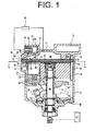
- FIG. 1 is a longitudinal sectional view of a swash plate type variable compressor according to a first preferred embodiment of the present invention;
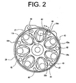
- FIG. 2 is a cross-sectional view taken along the line A-A in FIG.1;
- FIG. 3 is a partially enlarged cross-sectional view taken along the line B-B in FIG 2;
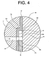
- FIG. 4 is an enlarged cross-sectional view showing the encircled portion P in FIG. 3;
- FIG 5 is a partially enlarged cross-sectional view of a swash plate type variable displacement compressor according to a second preferred embodiment of the present invention;
- FIG. 6 is a partially enlarged cross-sectional view of a swash plate type variable displacement compressor according to a third preferred embodiment of the present invention;
- FIG. 7 is a partially enlarged cross-sectional view of a swash plate type variable displacement compressor according to a fourth preferred embodiment of the present invention;
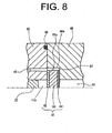
- FIG 8 is a partially enlarged cross-sectional view of a swash plate type variable displacement compressor according to the fifth preferred embodiment of the present invention;
- FIG. 9 is a longitudinal sectional view of a swash plate type variable displacement compressor according to a sixth preferred embodiment of the present invention;
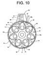
- FIG 10 is a cross-sectional view taken along the line C-C in FIG 9; and
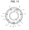
- FIG. 11 is an elevation view showing a rear housing of the compressor according to the sixth preferred embodiment as viewed from the front thereof.
- The following will describe a swash plate type variable displacement compressor (hereinafter referred to merely as "compressor") according to a first preferred embodiment of the present invention with reference to FIGS. 1 through 4. FIG. 1 shows a compressor which includes a
cylinder block 11, afront housing 12 as a first housing disposed to the front end of thecylinder block 11 and arear housing 14 as a second housing disposed to the rear end of thecylinder block 11 through avalve plate assembly 13 and agasket 27 which will be described below. "Housing block" in this embodiment refers to one of or both of thefront housing 12 and therear housing 14. Thefront housing 12, thecylinder block 11 and therear housing 14 are fastened together securely by a plurality of bolts 48 (only one bolt being shown in the drawing). Specifically thebolts 48 are inserted from the front wall of thefront housing 12 intobolt holes 46 in thecylinder block 11 and screwed into threadedholes 47 formed in therear housing 14. Positioningpins 49 fixed to the cylinder block 91 (shown in FIG 2) are inserted in holes (not shown) formed in therear housing 14 for positioning thereof. Thecylinder block 11 and thefront housing 12 cooperate to define therebetween acrank chamber 15. Adrive shaft 16 is supported by thecylinder block 11 and thefront housing 12 and extends through thecrank chamber 15. Thedrive shaft 16 is operatively connected to anengine 17 of a vehicle and is driven thereby to be rotated. - In the
crank chamber 15, alug plate 18 is fixed on thedrive shaft 16 for rotation therewith and aswash plate 19 is supported tiltably and also slidably along the axial direction of thedrive shaft 16. Hingemechanism 20 is located between thelug plate 18 and theswash plate 19. Thus, theswash plate 19 is synchronously rotatable with thelug plate 18 and thedrive shaft 16 through thehinge mechanism 20 and it is also tiltable while sliding in the longitudinal direction of the drive shaft 16- Inclination angle of theswash plate 19 is adjusted by adisplacement control valve 21. - The
cylinder block 11 is formed withplural cylinder bores 11a, only one of which is shown in FIG. 1, and a single-headed piston 22 is reciprocally slidably received in each ofcylinder bores 11a. Eachpiston 22 is engaged with outer peripheral portion of theswash plate 19 through a pair ofshoes 23. Thus, the rotational movement of theswash plate 19 driven by thedrive shaft 16 is converted into reciprocating movement of thepiston 22 by way of theshoes 23. Acompression chamber 24 is defined by thepiston 22, thegasket 27 and thevalve plate assembly 13 in the rear portion of each cylinder bore 11 a of the compressor or the right side of thecylinder bore 11 a as seen in FIG. 1. - A
suction chamber 25 is formed in a radially inner region of therear housing 14. Adischarge chamber 26 is formed in a radially outer region of therear housing 14. Between thecylinder block 11 and therear housing 14, thegasket 27 and thevalve plate assembly 13 are arranged in this order as viewed from the side of thecompression chamber 24. Thevalve plate assembly 13 includes a suctionvalve forming plate 28, avalve plate 29, a dischargevalve forming plate 30 and aretainer plate 31 that are arranged in this order from the front of the compressor. Thevalve plate 29 has formed therethrough asuction port 32 for introducing low-pressure refrigerant gas from thesuction chamber 25 into each of thecylinder bores 11a. Thevalve plate 29 has adischarge port 33 for discharging therethrough compressed high-pressure refrigerant gas from each of thecylinder bores 11a into thedischarge chamber 26. The suctionvalve forming plate 28 has asuction valve 28d for opening and closing thesuction port 32 and the dischargevalve forming plate 30 has adischarge valve 30a for opening and closing thedischarge port 33. - Refrigerant gas in the
suction chamber 25 is introduced into thecompression chamber 24 through thesuction port 32 by movement of the eachpiston 22 from the top dead center to the bottom dead center. Then, the refrigerant gas which is drawn into thecompression chamber 24 is compressed to a predetermined pressure by the movement of the eachpiston 22 from the bottom dead center to the top dead center, and flows into thedischarge chamber 26 through thedischarge port 33. - A
cylindrical hole 35 is formed in therear housing 14 in the vertical direction at the right side of thedischarge chamber 26 of therear housing 14 in FIG 1. The upper end of thecylindrical hole 35 is opened. Aseparation chamber 37 is formed by fitting anoil separator 36 into thecylindrical hole 35 and thisseparation chamber 37 communicates with thedischarge chamber 26 through adischarge passage 34. Refrigerant gas which is introduced into theseparation chamber 37 from thedischarge passage 34 swirls downwardly in the space between the cylindrical surface of theoil separator 36 and inner wall of theseparation chamber 37, so that oil G is centrifuged from the refrigerant gas, and then accumulated in the bottom of theseparation chamber 37. The refrigerant gas having the oil G separated therefrom is discharged into anexternal cooling circuit 39 through agas passage 38 in theoil separator 36. Due to the pressure differential, the oil G which is accumulated in the bottom of theseparation chamber 37 flows into anoil storage chamber 41 at the top of thecylinder block 11 through anoil passage 40 and stored therein. - As shown in FIG 2 through FIG. 4, the
cylinder block 11 is formed on the rear end face thereof with anannular recess 11b which is recessed in the axial direction of thedrive shaft 16 for receiving therein part of thegasket 27. That is, thegasket 27 has abent portion 27a which is formed by bending a part of thegasket 27 adjacent to thecylinder block 11 and thebent portion 27a of thegasket 27 is disposed in close contact with therecess 11 b of thecylinder block 11. A step, or astepped portion 11c is provided by thebent portion 27a of thegasket 27 and the recess 11b. Thestepped portion 11c is formed adjacent to thevalve plate assembly 13 and receives a part of thevalve plate assembly 13. The circular suctionvalve forming plate 28 which constitutes a part of thevalve plate assembly 13 is positioned between thebent portion 27a of thegasket 27 and thevalve plate 29 to be in close contact therewith. The outer diameter of the suctionvalve forming plate 28 is slightly smaller than the inner diameter of thegasket 27 at the inner peripheral surface of thebent portion 27a. Thus, as shown in an enlarged view of FIG. 4, a small space as an annular oil groove, or anannular oil passage 43 is provided by the steppedportion 11c and thevalve plate assembly 13. That is, theannular oil groove 43 is surrounded by an innerperipheral surface 27b of thebent portion 27a of thegasket 27, an outerperipheral surface 28c of the suctionvalve forming plate 28 and the front surface of thevalve plate 29. Theannular oil groove 43 of this embodiment extends along the entire circumference of the compressor. Alternatively, an annular oil groove may be formed with a length corresponding to a half, two thirds or one third of the entire circumferential length by changing the shape of the outer peripheral surface of the suctionvalve forming plate 28. - An
oil passage 42 is formed in the upper portion of thecylinder block 11. Theoil passage 42 is communicates with theoil storage chamber 41 and also with theannular oil groove 43 by way of ahole 27c in thegasket 27, thehole 28a in the suctionvalve forming plate 28 and anotch 44 which is formed adjacently to the outerperipheral surface 28c of the suctionvalve forming plate 28. Referring to FIG 1 and FIG. 2, thebolt hole 46 is located in the lower portion of thecylinder block 11. Thebolt hole 46 communicates with theannular oil groove 43 by way of a hole (not shown) in thegasket 27, ahole 28b in the suctionvalve forming plate 28 and a notch 45 adjacently in the outerperipheral surface 28c of the suctionvalve forming plate 28. - Thus, a return passage for oil in the
storage chamber 41 is constituted by theoil passage 42, theannular oil groove 43 and thebolt hole 46. Because theannular oil groove 43 has a narrowed space of a relatively long distance, the oil return passage has a throttle function. The oil G flows from theoil storage chamber 41 through theoil passage 42 to theannular oil groove 43, and flows further to thebolt hole 46 by way of eitherclockwise route 43a orcounter-clockwise route 43b of theannular oil groove 43 as shown is FIG. 2, and then is discharged into thecrank chamber 15 through thebolt hole 46. In the structure of FIG. 2, because the connection between theoil passage 42 and theannular oil groove 43 is located slightly rightward from the top as seen in FIG. 2, the oil G flows mainly through theclockwise route 43a. The connection between theoil passage 42 and theannular oil groove 43 may be located otherwise depending on the position of theoil storage chamber 41 and other structures. - The following will be described the operation of the compressor of the above structure. Because the
annular oil groove 43 is formed to extend along the whole circumference of the compressor, the high-temperature and high-pressure oil G accumulated in theoil storage chamber 41 and flowing to theannular oil groove 43 through theoil passage 42 then flows by way of theclockwise route 43a and/or thecounter-clockwise route 43b of theannular oil groove 43 to thebolt hole 46. Because theannular oil groove 43 having a small cross-sectional area is relatively long, and is formed adjacent to the outer periphery of the compressor and hence close to the ambient air, theannular oil groove 43 functions as a throttle passage. Thus, the pressure of the oil G is reduced, and the oil G is efficiently cooled by passing through theannular oil groove 43. The oil G whose pressure and temperature have been reduced, passes through the gap between thebolt 48 and thebolt hole 46, and then returns to the crankchamber 15. Thus, the oil G is used for lubrication of the sliding parts of the compressor. - Because the
annular oil groove 43 is a long passage, theannular oil groove 43 may be formed so as to have a relatively large cross-sectional area as compared to a shorter passage. In the case where a passage of either one of the clockwise route or counter-clockwise route is clogged with foreign matters, the oil G flows to thebolt hole 46 through the passage which is free of the clogging. In the case where the amount of the oil G in theoil storage chamber 41 is small or very small especially at startup of the compressor, the discharged refrigerant gas may pass through theoil storage chamber 41 and may enter directly into the oil return passage. However, the throttling function of theannular oil groove 43 prevents the refrigerant gas from entering into the oil return passage. - The following advantageous effects are obtained according to the compressor of the first preferred embodiment.
- (1) The
annular oil groove 43 is formed of a hermetically-closed space which is formed by the innerperipheral surface 27b of thebent portion 27a of thegasket 27 as a part of the steppedportion 11c, the outerperipheral surface 28c of the suctionvalve forming plate 28 and thevalve plate 29. By theannular oil groove 43, the oil return passage having a throttle function can be made easily. Furthermore, any additional process for forming a narrow passage in thevalve plate assembly 13 is not required and, therefore, the number of manufacturing processes for the compressor is reduced. - (2) Because the long
annular oil groove 43 is made of a throttled passage, it may be formed to have a relatively large cross-sectional area as compared to a shorter passage. Such a passage with the large cross-sectional area is advantageous in that it is less susceptible to clogging with foreign matters contained in the oil G. - (3) Because the pressure of the high-pressure oil G is reduced by passing through the
annular oil groove 43 functioning as a throttled passage with a narrow cross-sectional area, the oil G is flowed into the crank chamber under a low pressure. - (4) Because the long
annular oil groove 43 is formed adjacently to the outer peripheral portion of the compressor near ambient air, the high-pressure oil G can be efficiently cooled by passing through theannular oil groove 43. - (5) Because the
annular oil groove 43 is formed extending along the whole circumference of the compressor, the oil G flows into thebolt hole 46 through theclockwise route 43a and/or thecounter-clockwise route 43b. In case where the passage of either the clockwise route or counter-clockwise route is clogged with foreign matters, the oil G flows into thebolt hole 46 through the passage free of clogging, thereby improving the reliability in operation of the compressor. - (6) The
annular oil groove 43 connects thestorage chamber 41 to the crankchamber 15. The oil G which has been cooled and whose pressure has been reduced while passing through theannular oil groove 43 is returned to the crankchamber 15 through thebolt hole 46. Since thebolt hole 46 is used as an oil return passage, an additional work for providing an oil return passage may be eliminated. - (7) In the case when the amount of the oil G in the
storage chamber 41 becomes small or very small, the discharged refrigerant gas may passes through theoil storage chamber 41 and may enter directly into the oil return passage, but theannular oil groove 43 having the throttling function prevents the refrigerant gas from flowing into the oil return passage. - The following will describe a compressor according to a second preferred embodiment of the present invention with reference to FIG. 5. The second preferred embodiment differs from the first preferred embodiment in that the structures of the
recess 11b, thegasket 27 and thevalve plate assembly 13 are modified. The other structures of this compressor are substantially the same as those of the first preferred embodiment. Common or similar parts or elements are designated by the same reference numerals as those of the first preferred embodiment and, therefore, the explanation thereof will be omitted and only the modifications will be described. - In the second preferred embodiment, a
discharge chamber 68 is formed at a radially inner side of arear housing 66 and asuction chamber 67 is formed at a radially outer side of therear housing 66. The compressor has avalve plate assembly 60 which includes agasket 61, a suctionvalve forming plate 62, avalve plate 63, a dischargevalve forming plate 64 and aretainer plate 65, which are arranged in this order from the front of the compressor. In this embodiment, thegasket 61 is a part of thevalve plate assembly 60. Anannular recess 66a as a step, or stepped portion is formed in therear housing 66. The suctionvalve forming plate 62, thevalve plate 63, the dischargevalve forming plate 64 and theretainer plate 65 are provided at therecess 66a, and thegasket 61 is interposed betweencylinder block 11 and therear housing 66. - Outer peripheral surfaces of the suction
valve forming plate 62, thevalve plate 63, the dischargevalve forming plate 64, and theretainer plate 65 constitute outer peripheral surfaces 60a which face the inner peripheral surface of therecess 66a. Because the diameters of the outer peripheral surfaces are smaller than the diameter of the inner peripheral surface of therecess 66a, a hermetically -closed small or narrow space is formed by the dimensional differential. Accordingly, the narrow space as an annular oil groove, or anannular oil passage 71 is formed by therecess 66a as the stepped portion and thevalve plate assembly 60. That is, theoil groove 71 is formed by therecess 66a of therear housing 66, the outer peripheral surfaces 60a of the suctionvalve forming plate 62, thevalve plate 63, the dischargevalve forming plate 64 and theretainer plate 65 and the rear surface of thegasket 61. Thevalve plate 63 hasplural suction ports 69 through which low-pressure refrigerant gas is drawn into each of the cylinder bores 11a from thesuction chamber 67 andplural discharge ports 70 through which compressed high-pressure refrigerant gas is discharged from the cylinder bores 11a into thedischarge chamber 68. The suctionvalve forming plate 62 has a suction valve 62c for opening and closing thesuction port 69 and the dischargevalve forming plate 64 has adischarge valve 64a for opening and closing thedischarge port 70. - The
oil passage 42 which communicates with theoil storage chamber 41 provided at the top of thecylinder block 11. Theoil passage 42 is connected to theannular oil groove 71 by ahole 61a extending through thegasket 61, ahole 62a extending through the suctionvalve forming plate 62 and anotch 62b provided in the outer peripheral surface 60a of the suctionvalve forming plate 62. Thebolt hole 46 located in the lower portion of the cylinder block 11 (referred to FIG. 1 and FIG. 2) is connected by a hole and a notch (not shown) which are formed in thegasket 61 and the suctionvalve forming plate 62. The operation of the compressor of the second preferred embodiment is substantially the same as that of the first preferred embodiment and, therefore, the explanation will be omitted. - According to the compressor of the second preferred embodiment, the following advantageous effect is obtained, as well as those effects which have been already mentioned in the paragraphs (2) through (7) for the first preferred embodiment.
- (1) An oil return passage having the throttle function can be formed easily by the
annular oil groove 71. Theannular oil groove 71 which is formed as a hermetically-closed narrowed space formed by therecess 66a, the outer peripheral surfaces 60a of the suctionvalve forming plate 62, thevalve plate 63, the dischargevalve forming plate 64, theretainer plate 65, and thegasket 61. No special process is required for forming a narrowed oil return passage in thevalve plate assembly 60, so that the number of the manufacturing processes for the compressor is reduced. - The following will describe a compressor according to a third preferred embodiment of the present invention with reference to FIG. 6. The third preferred embodiment differs from the first preferred embodiment in that the structure of the recess is modified. The other structure of this compressor is substantially the same as that of the first preferred embodiment. Common or similar parts or elements are designated by the same reference numerals as those of the first preferred embodiment and, therefore, the description thereof will be omitted and the modifications will be described.
- The
annular recess 11b as a step, or a stepped portion is formed in the rear end surface of thecylinder block 11 in the form of a recess cut toward the front of the compressor in the axial direction of thedrive shaft 16. The compressor has avalve plate assembly 72 which includes agasket 73, a suctionvalve forming plate 74, avalve plate 75, a dischargevalve forming plate 76 and aretainer plate 77 which are arranged in this order from the front of the compressor. Thegasket 73 in this embodiment is a part ofvalve plate assembly 72. Thegasket 73 has abent portion 73a which is inserted into the space of therecess 11 b. The diameter of the outerperipheral surface 73c of thebent portion 73a is slightly smaller than the diameter of the outer peripheral surface of therecess 11b. Accordingly an annular oil groove, or anannular oil passage 78 is formed as a hermetically-closed narrow space between therecess 11 b and the outerperipheral surface 73c of thebent portion 73a of thegasket 73. A circular suctionvalve forming plate 74 is arranged on the side of the innerperipheral surface 73b of thebent portion 73a and pressed by thevalve plate 75 to be in close contact with thegasket 73. The suctionvalve forming plate 74 has asuction valve 74a for opening and closing thesuction port 32 and the dischargevalve forming plate 76 has adischarge valve 76a for opening and closing thedischarge port 33. Theannular oil groove 78 of the third preferred embodiment extends along substantially the entire circumference of the compressor as in the first preferred embodiment. Alternatively, theannular oil groove 78 may be formed with a half, two thirds or one third of the entire circumference by modifying the shape of the outer peripheral surface of the suctionvalve forming plate 74. - The
oil passage 42 communicates with theoil storage chamber 41 at the top of thecylinder block 11. Theoil passage 42 is arranged to be directly connected to theannular oil groove 78. Theannular oil groove 78 is a space provided at therecess 11b and connected directly to the bolt hole 46 (refer to FIG. 2) located in the lower part of thecylinder block 11. Thus, in the third embodiment, thenotches 44, 45 in the first preferred embodiment are not required, thereby the structure of theannular oil groove 78 is simplified. The operation of the compressor of the preferred embodiment is substantially the same as that of the first preferred embodiment and, therefore, the explanation thereof will be omitted. Furthermore, the third preferred embodiment has the same advantageous effects as those of the first preferred embodiment in addition to the above-described simple structure of theannular oil groove 78. - The following will describe a compressor according to a fourth preferred embodiment of the present invention with reference to FIG. 7. The fourth preferred embodiment differs from the third preferred embodiment in that the structure of the
recess 11b is slightly modified. Common or similar parts or elements are designated by the same reference numerals as those of the first and third preferred embodiments and, therefore, the explanation thereof will be omitted and only the modifications will be described. - The
annular recess 11b as a step, or a stepped portion is provided in the rear end surface of thecylinder block 11 in the form of a recess cut toward the front of the compressor in longitudinal direction of thedrive shaft 16. Anenlarged recess 79 is formed in the outer periphery of therecess 11b. In addition, the structures of therecess 11 b, thegasket 73 and the suctionvalve forming plate 74 are the same as the third preferred embodiment. Thegasket 73 has thebent portion 73a and is in close contact with thecylinder block 11. The suctionvalve forming plate 74 is arranged on the side of the innerperipheral surface 73b of thebent portion 73a and pressed by the suctionvalve forming plate 74 to be in close contact with thegasket 27. Thus, an annular oil groove, or anannular oil passage 80 is formed by therecess 11b and the outerperipheral surface 73c of thebent portion 73a of thegasket 73. The space of theannular oil groove 80 of this embodiment is enlarged by theenlarged recess 79. Theenlarged recess 79 is formed as an integral part of therecess 11 b by molding, or the like and, therefore, no special process is required for forming therecess 79. In the present preferred embodiment, theannular oil groove 80 with the enlarged cross-sectianal area serves to prevent thegroove 80 from being clogged with any foreign matters contained in the oil G, and hence to stabilize the flow of oil G returning to the crankchamber 15. Other advantageous effects are the same as those of the first and second preferred embodiments and, therefore, the explanation thereof is will be omitted. - The following will describe a compressor according to a fifth preferred embodiment of the present invention with reference to FIG. 8. The fifth preferred embodiment differs from the second preferred embodiment in that the structure of the
recess 66a and thevalve plate assembly 60 is modified and shows a case in which the present invention is applied to a double-headed piston type compressor. Common or similar parts or elements are designated by the same reference numerals as those of the second preferred embodiment and, therefore, the explanation thereof will be omitted and only the modifications will be described. - Fig. 8 shows a rear part of a double-headed piston type compressor wherein the present invention applied. The
recess 66a as a step, or a stepped portion is formed in therear housing 66 in the form of a recess cut rearward in axial direction of thedrive shaft 16. Avalve plate assembly 81 includes a suctionvalve forming plate 82, avalve plate 83 and agasket 84 which are arranged in this order from the front of the compressor. Thevalve plate assembly 81 is arranged in therecess 66a. The diameter of the outer peripheral surfaces of the suctionvalve forming plate 82, thevalve plate 83 and thegasket 84, or, the outerperipheral surface 81a of thevalve plate assembly 81 is smaller than the diameter of the inner periphery of therecess 66a, and a narrow space is formed by such difference of diameters. The suctionvalve forming plate 82 made of metal is disposed in direct contact with arear cylinder block 85 correspond to a cylinder block of the present invention made of metal, thereby producing a metal seal, and defining the cylinder bores 11a (only one cylinder bore being shown in the drawing). An o-ring 86 is provided between therear cylinder block 85 and therear housing 66 for sealing of the compressor. Thegasket 84 is provided in close sealing contact with the end surface of therecess 66a and cooperates with therear housing 66 to define thesuction chamber 67. - Thus, a closed narrow space is formed as an annular oil groove, or an
annular oil passage 87 which is formed by therecess 66a of therear housing 66, the outerperipheral surface 81a of thevalve plate assembly 81 and the rear surface of therear cylinder block 85. Theoil passage 42 communicating with the oil storage chamber 41 (refer to FIG 5) at the top of therear cylinder block 85 is formed to be directly connected to theannular oil groove 87. Similar to the second embodiment, theannular oil groove 87 is connected to thebolt hole 46 at the lower position of the cylinder block 85 (referring to FIG. 2). This preferred embodiment shows that theannular oil groove 87 is provided in therear housing 66 of the double-headed piston type compressor. According to the present invention, however, an annular oil groove similar to thegroove 87 of FIG 8 may be provided in the front housing. The advantageous effects of the present preferred embodiment are the same as those of the first and second embodiments, and the explanation thereof will be omitted. - The following will describe a compressor according to a sixth preferred embodiment of the present invention with reference to FIG. 9 through FIG. 11. The sixth preferred embodiment differs from the first preferred embodiment in that the installation of the
oil storage chamber 41 is modified and theannular oil groove 43 communicates with a positioning hole for locating positioning pin. Common or similar parts or elements are designated by the same reference numerals as those of the first preferred embodiment and, therefore, the explanation thereof will be omitted and only the modifications will be described. - In the present preferred embodiment, as shown in FIG. 9, the
discharge chamber 26 is formed in a radially inner region of therear housing 14 and thesuction chamber 25 is formed in a radially outer region of therear housing 14. Theseparation chamber 37 in which theoil separator 36 is installed is provided in aprotrusion 88 at the top of thecylinder block 11. Theseparation chamber 37 is formed by press fitting thecylindrical oil separator 36 into an upstandingcylindrical hole 35 formed in theprotrusion 88. As shown in FIG 10, theseparation chamber 37 communicates with thedischarge chamber 26 through adischarge passage 89. Thus, the refrigerant gas is introduced into theseparation chamber 37 from thedischarge chamber 26 through thedischarge passage 89. - The oil G centrifuged in the
separation chamber 37 is accumulated in theseparation chamber 37 at the bottom thereof. In this preferred embodiment, theseparation chamber 37 thus functions as an oil storage chamber. Anoil passage 90 is formed in the lower portion of theseparation chamber 37 and communicates through theoil passage 90 with theannular oil groove 43 which is formed in the outer peripheral portion of thevalve plate assembly 13. Thus, the oil G accumulated at the bottom of theseparation chamber 37 flows into theannular oil groove 43 through theoil passage 90. - As shown in FIG 10, the two
positioning pins 49 projecting rearward are provided in the upper and lower portions of thecylinder block 11. The positioning holes 91 are formed in the suctionvalve forming plate 28 for receiving therein the corresponding positioning pin 49- The positioning holes 91 are formed extending through thevalve plate assembly 13. The positioning holes 91 for thelower positioning pin 49 are connected to theannular oil groove 43 through anotch 92 formed in the outerperipheral surface 28c of the suctionvalve forming plate 28. - As shown in FIG 11, two
positioning holes 93 are formed in therear housing 14 with a predetermined depth for receiving therein thecorresponding positioning pin 49 which is fixed to thecylinder block 11. Thelower positioning hole 93 communicates with thesuction chamber 25 through apassage 94. When thepositioning pin 49 on thecylinder block 11 is inserted into thepositioning hole 93 of therear housing 14 for connection thereto, theannular oil groove 43 is connected to thesuction chamber 25 through thepositioning hole passage 94. - In operation of the compressor, the oil G accumulated in the
separation chamber 37 flows through theoil passage 90 to theannular oil groove 43 and further to thepositioning hole clockwise route 43a or thecounter-clockwise route 43b to flow to thesuction chamber 25 through thepassage 94. The operation of the compressor according to the sixth preferred embodiment is the substantially same as that of the first preferred embodiment, therefore, the explanation thereof will be omitted. - According to the compressor of the sixth preferred embodiment, the following advantageous effects are obtained. The advantageous effects as mentioned in the paragraphs (1) through (5) and (7) of the first preferred embodiment are common to the sixth preferred embodiment and, therefore, the advantageous effects other than the above will be described as follows.
- (1) By providing the
passage 94 for communication between thesuction chamber 25 and thepositioning hole 93, thepositioning hole 93 can be used as an oil return passage for fluid communication between theannular oil groove 43 and thesuction chamber 25. Thus, a manufacturing process for providing a new passage is not required. - (2) Since the
separation chamber 37 functions as an oil storage chamber, a separated oil storage chamber is not required. Thus, the number of manufacturing processes and of parts for providing an oil storage chamber is reduced. - The present invention is not limited to the embodiments described above but may be modified into various alternative embodiments as exemplified below.
- In the first through fifth preferred embodiments, the oil G in the
oil storage chamber 41 flows into thecrank chamber 15 by connecting theannular oil grooves bott hole 46. Alternatively, the oil G in theoil storage chamber 41 flows into thesuction chamber annular oil grooves suction chambers - In the first through fifth preferred embodiments, the
bolt hole 46 serves also as a passage for connecting theannular oil grooves chamber 15. Alternatively, the positioning hole formed in thecylinder block 11 for positioning of thecylinder block 11 and therear housing 14 may be used for communication instead of thebolt hole 46. Therear housing 14 may be positioned by inserting a positioning pin fixed to arear housing 14 into the positioning hole in thecylinder block 11 so as to communicate with thecrank chamber 15. Thus, the existing hole may be used as an oil return passage and, therefore, manufacturing process for providing a separated oil return passage is not required. - In the second preferred embodiment, the
annular oil groove 71 is formed by a space defined by therecess 66a of therear housing 14, the outer peripheral surfaces 60a of the suctionvalve forming plate 62, thevalve plate 63, the dischargevalve forming plate 64 and theretainer plate 65 and thegasket 61 forms theannular oil groove 71. Alternatively, a narrow space may be formed as an oil groove by therecess 66a of therear housing 14, the outer peripheral surface of the suctionvalve forming plate 62 and thevalve plate 63. Alternatively, a narrow space may be formed as an oil groove byrecess 66a of therear housing 14, the outer peripheral surfaces of the suctionvalve forming plate 62 and thevalve plate 63 and the dischargevalve forming plate 64. Similarly, in the fifth preferred embodiment, an oil groove may be formed by the suctionvalve forming plate 82 or both of the suctionvalve forming plate 82 and thevalve plate 83. - In the first and second preferred embodiments, the notch 45 for connecting the
annular oil groove bolt hole 46 is provided in the suctionvalve forming plate bolt hole 46 may be formed at a position where thebolt hole 46 communicates directly to theannular oil groove - In the first through fifth preferred embodiments, the
oil storage chamber 41 is provided at the top of thecylinder block 11 at the front side of theseparation chamber 37 and at the higher position than theseparation chamber 37. Alternatively, the oil storage chamber may be provided at any suitable position, such as on either lateral side of theseparation chamber 37 or under theseparation chamber 37. - In the above-described preferred embodiments, the present invention has been described as applied to a single-headed piston type variable displacement swash plate compressor. As is obvious to those skilled in the art, the present invention is applicable to various other types of compressor such as double-headed piston type, fixed displacement or wobble plate type compressor.
- Therefore, the present examples and embodiments are to be considered as illustrative and not restrictive, and the invention is not to be limited to the details given herein but may be modified within the scope of the appended claims.
- A refrigerant gas compressor includes a cylinder block formed with plural cylinder bores, a first housing disposed at the one end of the cylinder block, a second housing disposed at the other end of the cylinder block, a drive shaft supported by the cylinder block and one of the housings, a crank chamber formed in one of the housings, a suction chamber and a discharge chamber formed in one of the housings, a valve plate assembly disposed between the cylinder block and at least one of the housings, a stepped portion formed adjacent to the valve plate assembly to receive a part of the valve plate assembly. A storage chamber is provided for reserving therein oil separated from refrigerant gas. An oil groove is formed by the stepped portion and the valve plate assembly and connecting the storage chamber with one of the crank chamber and the suction chamber.
Claims (15)
- A refrigerant gas compressor comprising:a cylinder block (11, 85) formed with plural cylinder bores (11a);a first housing (12, 14, 66) disposed at one end of the cylinder block (19, 85);a second housing (12, 14, 66) disposed at the other end of the cylinder block (11, 85);a drive shaft (16) supported by the cylinder block (11, 85) and one of the housings (12, 14, 66);a crank chamber (15) formed in one of the housings (12, 14, 66);a swash plate (19) rotatably disposed in the crank chamber (15), the swash plate (19) being driven by the drive shaft (16);a suction chamber (25, 67) and a discharge chamber (26, 68) formed in one of the housings (12,14,66);a valve plate assembly (13, 60, 72, 81) disposed between the cylinder block (11, 85) and at least one of the housings (12, 14, 66); anda stepped portion (11c) formed adjacent to the valve plate assembly (13, 60, 72, 81) to receive a part of the valve plate assembly (13, 6D, 72, 81);characterized in that
a storage chamber (41) is provided for storing therein oil separated from refrigerant gas, and
in that an oil groove (43, 71, 78, 80, 87) is formed by the stepped portion (11c) and the valve plate assembly (13, 60, 72, 81) and connecting the storage chamber with one of the crank chamber and the suction chamber. - The compressor according to claim 1, further comprising a gasket (27) disposed between the cylinder block (11) and the valve plate assembly (13), wherein the stepped portion (11c) is formed by a recess (11b) in the cylinder block (11) and a bent portion (27a) of the gasket (27) adjacent to the recess (11b), wherein the oil groove (43) is formed by the bent portion (27a) and the valve plate assembly (13).
- The compressor according to claim 2, wherein the valve plate assembly (72) includes a suction valve forming plate (74) and a valve plate (29), wherein the oil groove (43) is formed by an outer peripheral surface of the suction valve forming plate (74), an inner peripheral surface of the bent portion (27a) of the gasket (27) and the front surface of the valve plate (29).
- The compressor according to claim 1, wherein the stepped portion (11c) is formed by a recess (11b) formed in the axial direction of the drive shaft (16) in one of the cylinder block (11), the first housing (12) and the second housing (14, 66).
- The compressor according to claim 4, wherein the recess (11b) is formed in the cylinder block (11), wherein the valve plate assembly (13. 60, 72, 81) includes a suction valve forming plate (74) and a gasket (73), wherein the gasket (73) has a bent portion (73a) adjacent to the recess (91b), wherein the oil groove (74) is formed by the recess (11b) and an outer peripheral surface of the bent portion (73a) of the gasket (73).
- The compressor according to claim 4, wherein the recess (11b) is formed in one of the first and the second housings (12, 14, 66), the valve plate assembly (60) including a suction valve forming plate (62), a valve plate (63) and a gasket (61), the oil groove (71) being formed by the recess (66a), the gasket (61) and at least an outer peripheral surface of the suction valve forming plate (62).
- The compressor according to claim 6, wherein the valve plate assembly (60) further includes a discharge valve forming plate (64).
- The compressor according to claim 6, wherein the valve plate assembly (60) further includes a retainer plate (65).
- The compressor according to claim 4, wherein the recess (66a) is formed in one of the first and second housings (12, 14), the oil groove (87) being formed by the recess (66a) in one of the first and second housings (12, 14), a peripheral surface of the valve plate assembly (81) and the cylinder block (85).
- The compressor according to claim 9, wherein the valve plate assembly (81) further includes a suction valve forming plate (82).
- The compressor according to any one of claim 1 through claim 10, wherein the oil groove (43, 71, 78, 80, 87) extends annularly along the entire circumference of one of the cylinder block (11, 85), the first housing (12, 14, 66) and second housing (12, 14, 66).
- The compressor according to any one of claim 1 through claim 11, wherein the oil groove (43, 71, 78, 80, 87) is formed adjacently to an outer peripheral portion of the compressor.
- The compressor according to any one of claim 1 through claim 12, wherein the cylinder block (11, 85) has a bolt hole (46) for receiving therein a bolt (48), the bolt hole (46) communicates with the crank chamber (15) through the oil groove (43, 71, 78, 80, 87).
- The compressor according to any one of claim 1 through claim 13, wherein the cylinder block (11) has a positioning hole (91) for receiving therein a positioning pin (49), the positioning hole (91) communicates with the crank chamber (15) through the oil groove (43).
- The compressor according to any one of claim 1 through claim 12 and claim 14, wherein one of the first and second housing (12, 14) has a positioning hole (93) for receiving therein a positioning pin (49), the positioning hole (93) communicates with the suction chamber (25) through the oil groove (43).
Applications Claiming Priority (2)
| Application Number | Priority Date | Filing Date | Title |
|---|---|---|---|
| JP2006139734 | 2006-05-19 | ||
| JP2006352221A JP4737076B2 (en) | 2006-05-19 | 2006-12-27 | Compressor |
Publications (3)
| Publication Number | Publication Date |
|---|---|
| EP1857676A2 true EP1857676A2 (en) | 2007-11-21 |
| EP1857676A3 EP1857676A3 (en) | 2012-06-27 |
| EP1857676B1 EP1857676B1 (en) | 2014-04-02 |
Family
ID=38191140
Family Applications (1)
| Application Number | Title | Priority Date | Filing Date |
|---|---|---|---|
| EP07108456.0A Not-in-force EP1857676B1 (en) | 2006-05-19 | 2007-05-18 | Refrigerant gas compressor |
Country Status (5)
| Country | Link |
|---|---|
| US (1) | US7976288B2 (en) |
| EP (1) | EP1857676B1 (en) |
| JP (1) | JP4737076B2 (en) |
| KR (1) | KR100840916B1 (en) |
| BR (1) | BRPI0705980A (en) |
Cited By (2)
| Publication number | Priority date | Publication date | Assignee | Title |
|---|---|---|---|---|
| CN102947592A (en) * | 2010-06-21 | 2013-02-27 | 三电有限公司 | variable capacity compressor |
| US10598416B2 (en) | 2013-11-04 | 2020-03-24 | Carrier Corporation | Refrigeration circuit with oil separation |
Families Citing this family (5)
| Publication number | Priority date | Publication date | Assignee | Title |
|---|---|---|---|---|
| JP2008082256A (en) * | 2006-09-28 | 2008-04-10 | Toyota Industries Corp | Lubricating device for swash plate type compressor |
| JP5065120B2 (en) * | 2008-03-28 | 2012-10-31 | サンデン株式会社 | Reciprocating compressor |
| JP5697022B2 (en) * | 2010-12-14 | 2015-04-08 | サンデン株式会社 | Variable capacity compressor |
| JP2012202394A (en) * | 2011-03-28 | 2012-10-22 | Toyota Industries Corp | Swash plate type variable displacement compressor |
| JP5846012B2 (en) * | 2012-03-30 | 2016-01-20 | 株式会社豊田自動織機 | Swash plate compressor |
Citations (3)
| Publication number | Priority date | Publication date | Assignee | Title |
|---|---|---|---|---|
| US5009286A (en) | 1988-12-02 | 1991-04-23 | Kabushiki Kaisha Toyoda Jidoshokki Seisakushi | Lubricating oil supplying mechanism in swash plate type compressor |
| JPH09209928A (en) | 1996-01-30 | 1997-08-12 | Toyota Autom Loom Works Ltd | Swash plate type compressor |
| JP2004044463A (en) | 2002-07-11 | 2004-02-12 | Denso Corp | Compressor |
Family Cites Families (18)
| Publication number | Priority date | Publication date | Assignee | Title |
|---|---|---|---|---|
| US3215341A (en) * | 1963-01-18 | 1965-11-02 | Gen Motors Corp | Refrigerating apparatus |
| JPH059512Y2 (en) * | 1987-03-11 | 1993-03-09 | ||
| JPH07332239A (en) * | 1994-06-03 | 1995-12-22 | Toyota Autom Loom Works Ltd | Reciprocating compressor |
| JP3144616B2 (en) | 1995-04-03 | 2001-03-12 | 株式会社豊田自動織機製作所 | Swash plate compressor |
| JP3120697B2 (en) * | 1995-05-25 | 2000-12-25 | 株式会社豊田自動織機製作所 | Swash plate compressor |
| JP3085514B2 (en) | 1995-06-08 | 2000-09-11 | 株式会社豊田自動織機製作所 | Compressor |
| JPH09287569A (en) | 1996-04-25 | 1997-11-04 | Toyota Autom Loom Works Ltd | Lubricating device for swash plate type compressor |
| JPH10281060A (en) * | 1996-12-10 | 1998-10-20 | Toyota Autom Loom Works Ltd | Variable displacement compressor |
| JPH10196536A (en) * | 1997-01-13 | 1998-07-31 | Toyota Autom Loom Works Ltd | Deterioration preventing structure of sealing member in reciprocating compressor |
| JPH11257217A (en) * | 1998-03-16 | 1999-09-21 | Toyota Autom Loom Works Ltd | One side variable displacement compressor |
| KR100363930B1 (en) * | 1999-04-01 | 2002-12-11 | 가부시키가이샤 도요다 지도숏키 | The positioning structure of valve forming body in compressor |
| JP2000345960A (en) * | 1999-04-01 | 2000-12-12 | Toyota Autom Loom Works Ltd | Positioning structure of valve forming body in compressor |
| JP2001027177A (en) * | 1999-07-15 | 2001-01-30 | Zexel Valeo Climate Control Corp | Variable displacement swash plate type compressor |
| KR100318418B1 (en) * | 1999-12-30 | 2001-12-22 | 신영주 | Oil separator embeded in compressor |
| KR100719935B1 (en) * | 2000-12-21 | 2007-05-18 | 한라공조주식회사 | Oil Separator with Compressor |
| JP4021232B2 (en) * | 2002-04-01 | 2007-12-12 | サンデン株式会社 | Compressor seal structure |
| JP4408389B2 (en) * | 2004-05-10 | 2010-02-03 | サンデン株式会社 | Swash plate compressor |
| JP2007192201A (en) * | 2006-01-23 | 2007-08-02 | Toyota Industries Corp | Oil recovery structure in compressor |
-
2006
- 2006-12-27 JP JP2006352221A patent/JP4737076B2/en not_active Expired - Fee Related
-
2007
- 2007-04-02 KR KR1020070032233A patent/KR100840916B1/en not_active Expired - Fee Related
- 2007-05-18 US US11/750,466 patent/US7976288B2/en not_active Expired - Fee Related
- 2007-05-18 BR BRPI0705980-9A patent/BRPI0705980A/en not_active IP Right Cessation
- 2007-05-18 EP EP07108456.0A patent/EP1857676B1/en not_active Not-in-force
Patent Citations (3)
| Publication number | Priority date | Publication date | Assignee | Title |
|---|---|---|---|---|
| US5009286A (en) | 1988-12-02 | 1991-04-23 | Kabushiki Kaisha Toyoda Jidoshokki Seisakushi | Lubricating oil supplying mechanism in swash plate type compressor |
| JPH09209928A (en) | 1996-01-30 | 1997-08-12 | Toyota Autom Loom Works Ltd | Swash plate type compressor |
| JP2004044463A (en) | 2002-07-11 | 2004-02-12 | Denso Corp | Compressor |
Cited By (4)
| Publication number | Priority date | Publication date | Assignee | Title |
|---|---|---|---|---|
| CN102947592A (en) * | 2010-06-21 | 2013-02-27 | 三电有限公司 | variable capacity compressor |
| US9011109B2 (en) | 2010-06-21 | 2015-04-21 | Sanden Corporation | Variable Capacity Compressor |
| CN102947592B (en) * | 2010-06-21 | 2015-09-09 | 三电有限公司 | Variable displacement compressor |
| US10598416B2 (en) | 2013-11-04 | 2020-03-24 | Carrier Corporation | Refrigeration circuit with oil separation |
Also Published As
| Publication number | Publication date |
|---|---|
| JP2007332949A (en) | 2007-12-27 |
| US20070269319A1 (en) | 2007-11-22 |
| EP1857676B1 (en) | 2014-04-02 |
| KR20070111967A (en) | 2007-11-22 |
| JP4737076B2 (en) | 2011-07-27 |
| EP1857676A3 (en) | 2012-06-27 |
| US7976288B2 (en) | 2011-07-12 |
| KR100840916B1 (en) | 2008-06-24 |
| BRPI0705980A (en) | 2008-09-23 |
Similar Documents
| Publication | Publication Date | Title |
|---|---|---|
| EP1857676B1 (en) | Refrigerant gas compressor | |
| EP2055952B1 (en) | Variable displacement compressor | |
| US20070140870A1 (en) | Refrigerant compressor having an oil separator | |
| US8991296B2 (en) | Compressor | |
| US5800133A (en) | Compressor with discharge chamber relief valve | |
| EP0926341A2 (en) | Oil recovery device for compressors | |
| KR19980063912A (en) | Variable capacity compressor | |
| US20120237369A1 (en) | Cylinder block of piston-type compressor and method for manufacturing the same | |
| US20090081060A1 (en) | Compressor | |
| EP1508695B1 (en) | Reciprocating compressor | |
| US20070175239A1 (en) | Refrigerant compressor | |
| JP5413851B2 (en) | Refrigerant compressor | |
| US8197229B2 (en) | Double-headed piston type compressor | |
| CN100557238C (en) | Refrigerant gas compressor | |
| US5947698A (en) | Piston type compressor | |
| US20060228229A1 (en) | Piston type compressor | |
| US20070177991A1 (en) | Oil separation structure in compressor | |
| US5380163A (en) | Gas guiding mechanism in a piston type compressor | |
| US9651036B2 (en) | Swash plate type variable displacement compressor | |
| EP1930591A2 (en) | Compressor having a mechanism for separating and recovering lubrication oil | |
| US20070031264A1 (en) | Double-headed piston type compressor | |
| JP6469994B2 (en) | Compressor | |
| JP2000027756A (en) | Compressor | |
| US20080193304A1 (en) | Piston Type Compressor | |
| JP2021038703A (en) | Reciprocation type compressor |
Legal Events
| Date | Code | Title | Description |
|---|---|---|---|
| PUAI | Public reference made under article 153(3) epc to a published international application that has entered the european phase |
Free format text: ORIGINAL CODE: 0009012 |
|
| 17P | Request for examination filed |
Effective date: 20070518 |
|
| AK | Designated contracting states |
Kind code of ref document: A2 Designated state(s): AT BE BG CH CY CZ DE DK EE ES FI FR GB GR HU IE IS IT LI LT LU LV MC MT NL PL PT RO SE SI SK TR |
|
| AX | Request for extension of the european patent |
Extension state: AL BA HR MK YU |
|
| PUAL | Search report despatched |
Free format text: ORIGINAL CODE: 0009013 |
|
| AK | Designated contracting states |
Kind code of ref document: A3 Designated state(s): AT BE BG CH CY CZ DE DK EE ES FI FR GB GR HU IE IS IT LI LT LU LV MC MT NL PL PT RO SE SI SK TR |
|
| AX | Request for extension of the european patent |
Extension state: AL BA HR MK RS |
|
| RIC1 | Information provided on ipc code assigned before grant |
Ipc: F04B 27/10 20060101AFI20120523BHEP Ipc: F04B 39/12 20060101ALI20120523BHEP Ipc: F04B 39/10 20060101ALI20120523BHEP |
|
| AKX | Designation fees paid |
Designated state(s): AT BE BG CH CY CZ DE DK EE ES FI FR GB GR HU IE IS IT LI LT LU LV MC MT NL PL PT RO SE SI SK TR |
|
| GRAP | Despatch of communication of intention to grant a patent |
Free format text: ORIGINAL CODE: EPIDOSNIGR1 |
|
| RIC1 | Information provided on ipc code assigned before grant |
Ipc: F04B 39/10 20060101ALI20130923BHEP Ipc: F04B 27/10 20060101AFI20130923BHEP Ipc: F04B 39/12 20060101ALI20130923BHEP |
|
| INTG | Intention to grant announced |
Effective date: 20131016 |
|
| RIN1 | Information on inventor provided before grant (corrected) |
Inventor name: NAKAIMA, HIROYUKI Inventor name: TARUTANI, TOMOJI Inventor name: INOUE, YOSHINORI Inventor name: KOEDA, NAOKI Inventor name: KANAI, AKINOBU |
|
| GRAS | Grant fee paid |
Free format text: ORIGINAL CODE: EPIDOSNIGR3 |
|
| GRAA | (expected) grant |
Free format text: ORIGINAL CODE: 0009210 |
|
| AK | Designated contracting states |
Kind code of ref document: B1 Designated state(s): AT BE BG CH CY CZ DE DK EE ES FI FR GB GR HU IE IS IT LI LT LU LV MC MT NL PL PT RO SE SI SK TR |
|
| REG | Reference to a national code |
Ref country code: GB Ref legal event code: FG4D |
|
| REG | Reference to a national code |
Ref country code: AT Ref legal event code: REF Ref document number: 660305 Country of ref document: AT Kind code of ref document: T Effective date: 20140415 Ref country code: CH Ref legal event code: EP |
|
| REG | Reference to a national code |
Ref country code: IE Ref legal event code: FG4D |
|
| REG | Reference to a national code |
Ref country code: DE Ref legal event code: R096 Ref document number: 602007035857 Country of ref document: DE Effective date: 20140515 |
|
| REG | Reference to a national code |
Ref country code: AT Ref legal event code: MK05 Ref document number: 660305 Country of ref document: AT Kind code of ref document: T Effective date: 20140402 |
|
| REG | Reference to a national code |
Ref country code: NL Ref legal event code: VDEP Effective date: 20140402 |
|
| PGFP | Annual fee paid to national office [announced via postgrant information from national office to epo] |
Ref country code: DE Payment date: 20140528 Year of fee payment: 8 |
|
| REG | Reference to a national code |
Ref country code: LT Ref legal event code: MG4D |
|
| PG25 | Lapsed in a contracting state [announced via postgrant information from national office to epo] |
Ref country code: BG Free format text: LAPSE BECAUSE OF FAILURE TO SUBMIT A TRANSLATION OF THE DESCRIPTION OR TO PAY THE FEE WITHIN THE PRESCRIBED TIME-LIMIT Effective date: 20140702 Ref country code: LT Free format text: LAPSE BECAUSE OF FAILURE TO SUBMIT A TRANSLATION OF THE DESCRIPTION OR TO PAY THE FEE WITHIN THE PRESCRIBED TIME-LIMIT Effective date: 20140402 Ref country code: GR Free format text: LAPSE BECAUSE OF FAILURE TO SUBMIT A TRANSLATION OF THE DESCRIPTION OR TO PAY THE FEE WITHIN THE PRESCRIBED TIME-LIMIT Effective date: 20140703 Ref country code: NL Free format text: LAPSE BECAUSE OF FAILURE TO SUBMIT A TRANSLATION OF THE DESCRIPTION OR TO PAY THE FEE WITHIN THE PRESCRIBED TIME-LIMIT Effective date: 20140402 Ref country code: FI Free format text: LAPSE BECAUSE OF FAILURE TO SUBMIT A TRANSLATION OF THE DESCRIPTION OR TO PAY THE FEE WITHIN THE PRESCRIBED TIME-LIMIT Effective date: 20140402 Ref country code: CZ Free format text: LAPSE BECAUSE OF FAILURE TO SUBMIT A TRANSLATION OF THE DESCRIPTION OR TO PAY THE FEE WITHIN THE PRESCRIBED TIME-LIMIT Effective date: 20140402 Ref country code: CY Free format text: LAPSE BECAUSE OF FAILURE TO SUBMIT A TRANSLATION OF THE DESCRIPTION OR TO PAY THE FEE WITHIN THE PRESCRIBED TIME-LIMIT Effective date: 20140402 Ref country code: IS Free format text: LAPSE BECAUSE OF FAILURE TO SUBMIT A TRANSLATION OF THE DESCRIPTION OR TO PAY THE FEE WITHIN THE PRESCRIBED TIME-LIMIT Effective date: 20140802 |
|
| PG25 | Lapsed in a contracting state [announced via postgrant information from national office to epo] |
Ref country code: ES Free format text: LAPSE BECAUSE OF FAILURE TO SUBMIT A TRANSLATION OF THE DESCRIPTION OR TO PAY THE FEE WITHIN THE PRESCRIBED TIME-LIMIT Effective date: 20140402 Ref country code: PL Free format text: LAPSE BECAUSE OF FAILURE TO SUBMIT A TRANSLATION OF THE DESCRIPTION OR TO PAY THE FEE WITHIN THE PRESCRIBED TIME-LIMIT Effective date: 20140402 Ref country code: LV Free format text: LAPSE BECAUSE OF FAILURE TO SUBMIT A TRANSLATION OF THE DESCRIPTION OR TO PAY THE FEE WITHIN THE PRESCRIBED TIME-LIMIT Effective date: 20140402 Ref country code: SE Free format text: LAPSE BECAUSE OF FAILURE TO SUBMIT A TRANSLATION OF THE DESCRIPTION OR TO PAY THE FEE WITHIN THE PRESCRIBED TIME-LIMIT Effective date: 20140402 Ref country code: AT Free format text: LAPSE BECAUSE OF FAILURE TO SUBMIT A TRANSLATION OF THE DESCRIPTION OR TO PAY THE FEE WITHIN THE PRESCRIBED TIME-LIMIT Effective date: 20140402 |
|
| PG25 | Lapsed in a contracting state [announced via postgrant information from national office to epo] |
Ref country code: PT Free format text: LAPSE BECAUSE OF FAILURE TO SUBMIT A TRANSLATION OF THE DESCRIPTION OR TO PAY THE FEE WITHIN THE PRESCRIBED TIME-LIMIT Effective date: 20140804 |
|
| REG | Reference to a national code |
Ref country code: CH Ref legal event code: PL |
|
| REG | Reference to a national code |
Ref country code: DE Ref legal event code: R097 Ref document number: 602007035857 Country of ref document: DE |
|
| PG25 | Lapsed in a contracting state [announced via postgrant information from national office to epo] |
Ref country code: RO Free format text: LAPSE BECAUSE OF FAILURE TO SUBMIT A TRANSLATION OF THE DESCRIPTION OR TO PAY THE FEE WITHIN THE PRESCRIBED TIME-LIMIT Effective date: 20140402 Ref country code: BE Free format text: LAPSE BECAUSE OF FAILURE TO SUBMIT A TRANSLATION OF THE DESCRIPTION OR TO PAY THE FEE WITHIN THE PRESCRIBED TIME-LIMIT Effective date: 20140402 Ref country code: CH Free format text: LAPSE BECAUSE OF NON-PAYMENT OF DUE FEES Effective date: 20140531 Ref country code: LI Free format text: LAPSE BECAUSE OF NON-PAYMENT OF DUE FEES Effective date: 20140531 Ref country code: SK Free format text: LAPSE BECAUSE OF FAILURE TO SUBMIT A TRANSLATION OF THE DESCRIPTION OR TO PAY THE FEE WITHIN THE PRESCRIBED TIME-LIMIT Effective date: 20140402 Ref country code: EE Free format text: LAPSE BECAUSE OF FAILURE TO SUBMIT A TRANSLATION OF THE DESCRIPTION OR TO PAY THE FEE WITHIN THE PRESCRIBED TIME-LIMIT Effective date: 20140402 Ref country code: DK Free format text: LAPSE BECAUSE OF FAILURE TO SUBMIT A TRANSLATION OF THE DESCRIPTION OR TO PAY THE FEE WITHIN THE PRESCRIBED TIME-LIMIT Effective date: 20140402 Ref country code: MC Free format text: LAPSE BECAUSE OF FAILURE TO SUBMIT A TRANSLATION OF THE DESCRIPTION OR TO PAY THE FEE WITHIN THE PRESCRIBED TIME-LIMIT Effective date: 20140402 |
|
| PLBE | No opposition filed within time limit |
Free format text: ORIGINAL CODE: 0009261 |
|
| STAA | Information on the status of an ep patent application or granted ep patent |
Free format text: STATUS: NO OPPOSITION FILED WITHIN TIME LIMIT |
|
| REG | Reference to a national code |
Ref country code: IE Ref legal event code: MM4A |
|
| REG | Reference to a national code |
Ref country code: FR Ref legal event code: ST Effective date: 20150130 |
|
| 26N | No opposition filed |
Effective date: 20150106 |
|
| GBPC | Gb: european patent ceased through non-payment of renewal fee |
Effective date: 20140702 |
|
| PG25 | Lapsed in a contracting state [announced via postgrant information from national office to epo] |
Ref country code: IT Free format text: LAPSE BECAUSE OF FAILURE TO SUBMIT A TRANSLATION OF THE DESCRIPTION OR TO PAY THE FEE WITHIN THE PRESCRIBED TIME-LIMIT Effective date: 20140402 |
|
| REG | Reference to a national code |
Ref country code: DE Ref legal event code: R097 Ref document number: 602007035857 Country of ref document: DE Effective date: 20150106 |
|
| PG25 | Lapsed in a contracting state [announced via postgrant information from national office to epo] |
Ref country code: IE Free format text: LAPSE BECAUSE OF NON-PAYMENT OF DUE FEES Effective date: 20140518 |
|
| PG25 | Lapsed in a contracting state [announced via postgrant information from national office to epo] |
Ref country code: FR Free format text: LAPSE BECAUSE OF NON-PAYMENT OF DUE FEES Effective date: 20140602 Ref country code: GB Free format text: LAPSE BECAUSE OF NON-PAYMENT OF DUE FEES Effective date: 20140702 |
|
| PG25 | Lapsed in a contracting state [announced via postgrant information from national office to epo] |
Ref country code: SI Free format text: LAPSE BECAUSE OF FAILURE TO SUBMIT A TRANSLATION OF THE DESCRIPTION OR TO PAY THE FEE WITHIN THE PRESCRIBED TIME-LIMIT Effective date: 20140402 |
|
| REG | Reference to a national code |
Ref country code: DE Ref legal event code: R119 Ref document number: 602007035857 Country of ref document: DE |
|
| PG25 | Lapsed in a contracting state [announced via postgrant information from national office to epo] |
Ref country code: MT Free format text: LAPSE BECAUSE OF FAILURE TO SUBMIT A TRANSLATION OF THE DESCRIPTION OR TO PAY THE FEE WITHIN THE PRESCRIBED TIME-LIMIT Effective date: 20140402 |
|
| PG25 | Lapsed in a contracting state [announced via postgrant information from national office to epo] |
Ref country code: DE Free format text: LAPSE BECAUSE OF NON-PAYMENT OF DUE FEES Effective date: 20151201 |
|
| PG25 | Lapsed in a contracting state [announced via postgrant information from national office to epo] |
Ref country code: HU Free format text: LAPSE BECAUSE OF FAILURE TO SUBMIT A TRANSLATION OF THE DESCRIPTION OR TO PAY THE FEE WITHIN THE PRESCRIBED TIME-LIMIT; INVALID AB INITIO Effective date: 20070518 Ref country code: LU Free format text: LAPSE BECAUSE OF NON-PAYMENT OF DUE FEES Effective date: 20140518 Ref country code: TR Free format text: LAPSE BECAUSE OF FAILURE TO SUBMIT A TRANSLATION OF THE DESCRIPTION OR TO PAY THE FEE WITHIN THE PRESCRIBED TIME-LIMIT Effective date: 20140402 |