EP1857651A2 - Exhaust gas treating device for an internal combustion engine - Google Patents
Exhaust gas treating device for an internal combustion engine Download PDFInfo
- Publication number
- EP1857651A2 EP1857651A2 EP07104112A EP07104112A EP1857651A2 EP 1857651 A2 EP1857651 A2 EP 1857651A2 EP 07104112 A EP07104112 A EP 07104112A EP 07104112 A EP07104112 A EP 07104112A EP 1857651 A2 EP1857651 A2 EP 1857651A2
- Authority
- EP
- European Patent Office
- Prior art keywords
- exhaust
- treatment device
- exhaust gas
- mixing chamber
- exhaust pipe
- Prior art date
- Legal status (The legal status is an assumption and is not a legal conclusion. Google has not performed a legal analysis and makes no representation as to the accuracy of the status listed.)
- Granted
Links
- 238000002485 combustion reaction Methods 0.000 title claims description 4
- 239000003054 catalyst Substances 0.000 claims abstract description 13
- 230000003197 catalytic effect Effects 0.000 claims description 10
- 238000010521 absorption reaction Methods 0.000 claims description 7
- 239000002245 particle Substances 0.000 claims description 3
- 239000002184 metal Substances 0.000 claims description 2
- 238000010531 catalytic reduction reaction Methods 0.000 abstract description 2
- 239000007789 gas Substances 0.000 description 40
- MWUXSHHQAYIFBG-UHFFFAOYSA-N nitrogen oxide Inorganic materials O=[N] MWUXSHHQAYIFBG-UHFFFAOYSA-N 0.000 description 21
- XSQUKJJJFZCRTK-UHFFFAOYSA-N Urea Chemical compound NC(N)=O XSQUKJJJFZCRTK-UHFFFAOYSA-N 0.000 description 9
- 239000004202 carbamide Substances 0.000 description 9
- 239000003638 chemical reducing agent Substances 0.000 description 7
- QGZKDVFQNNGYKY-UHFFFAOYSA-N Ammonia Chemical compound N QGZKDVFQNNGYKY-UHFFFAOYSA-N 0.000 description 6
- 238000000034 method Methods 0.000 description 6
- 230000009467 reduction Effects 0.000 description 6
- 238000006722 reduction reaction Methods 0.000 description 6
- 230000008569 process Effects 0.000 description 4
- 229910021529 ammonia Inorganic materials 0.000 description 3
- 230000008901 benefit Effects 0.000 description 3
- 238000011156 evaluation Methods 0.000 description 3
- 230000001419 dependent effect Effects 0.000 description 2
- 239000003344 environmental pollutant Substances 0.000 description 2
- 231100000719 pollutant Toxicity 0.000 description 2
- UGFAIRIUMAVXCW-UHFFFAOYSA-N Carbon monoxide Chemical compound [O+]#[C-] UGFAIRIUMAVXCW-UHFFFAOYSA-N 0.000 description 1
- 230000009471 action Effects 0.000 description 1
- 238000006555 catalytic reaction Methods 0.000 description 1
- 238000006243 chemical reaction Methods 0.000 description 1
- 238000004140 cleaning Methods 0.000 description 1
- 238000010276 construction Methods 0.000 description 1
- 238000013461 design Methods 0.000 description 1
- 238000005516 engineering process Methods 0.000 description 1
- 239000003546 flue gas Substances 0.000 description 1
- 238000006460 hydrolysis reaction Methods 0.000 description 1
- 238000002955 isolation Methods 0.000 description 1
- 238000005259 measurement Methods 0.000 description 1
- 230000004048 modification Effects 0.000 description 1
- 238000012986 modification Methods 0.000 description 1
- 238000011946 reduction process Methods 0.000 description 1
- 230000001105 regulatory effect Effects 0.000 description 1
- 230000003584 silencer Effects 0.000 description 1
- 239000004071 soot Substances 0.000 description 1
- WTHDKMILWLGDKL-UHFFFAOYSA-N urea;hydrate Chemical compound O.NC(N)=O WTHDKMILWLGDKL-UHFFFAOYSA-N 0.000 description 1
- XLYOFNOQVPJJNP-UHFFFAOYSA-N water Substances O XLYOFNOQVPJJNP-UHFFFAOYSA-N 0.000 description 1
Images


Classifications
-
- F—MECHANICAL ENGINEERING; LIGHTING; HEATING; WEAPONS; BLASTING
- F01—MACHINES OR ENGINES IN GENERAL; ENGINE PLANTS IN GENERAL; STEAM ENGINES
- F01N—GAS-FLOW SILENCERS OR EXHAUST APPARATUS FOR MACHINES OR ENGINES IN GENERAL; GAS-FLOW SILENCERS OR EXHAUST APPARATUS FOR INTERNAL COMBUSTION ENGINES
- F01N3/00—Exhaust or silencing apparatus having means for purifying, rendering innocuous, or otherwise treating exhaust
- F01N3/08—Exhaust or silencing apparatus having means for purifying, rendering innocuous, or otherwise treating exhaust for rendering innocuous
- F01N3/10—Exhaust or silencing apparatus having means for purifying, rendering innocuous, or otherwise treating exhaust for rendering innocuous by thermal or catalytic conversion of noxious components of exhaust
- F01N3/24—Exhaust or silencing apparatus having means for purifying, rendering innocuous, or otherwise treating exhaust for rendering innocuous by thermal or catalytic conversion of noxious components of exhaust characterised by constructional aspects of converting apparatus
- F01N3/28—Construction of catalytic reactors
- F01N3/2882—Catalytic reactors combined or associated with other devices, e.g. exhaust silencers or other exhaust purification devices
- F01N3/2885—Catalytic reactors combined or associated with other devices, e.g. exhaust silencers or other exhaust purification devices with exhaust silencers in a single housing
-
- F—MECHANICAL ENGINEERING; LIGHTING; HEATING; WEAPONS; BLASTING
- F01—MACHINES OR ENGINES IN GENERAL; ENGINE PLANTS IN GENERAL; STEAM ENGINES
- F01N—GAS-FLOW SILENCERS OR EXHAUST APPARATUS FOR MACHINES OR ENGINES IN GENERAL; GAS-FLOW SILENCERS OR EXHAUST APPARATUS FOR INTERNAL COMBUSTION ENGINES
- F01N1/00—Silencing apparatus characterised by method of silencing
- F01N1/08—Silencing apparatus characterised by method of silencing by reducing exhaust energy by throttling or whirling
- F01N1/084—Silencing apparatus characterised by method of silencing by reducing exhaust energy by throttling or whirling the gases flowing through the silencer two or more times longitudinally in opposite directions, e.g. using parallel or concentric tubes
-
- F—MECHANICAL ENGINEERING; LIGHTING; HEATING; WEAPONS; BLASTING
- F01—MACHINES OR ENGINES IN GENERAL; ENGINE PLANTS IN GENERAL; STEAM ENGINES
- F01N—GAS-FLOW SILENCERS OR EXHAUST APPARATUS FOR MACHINES OR ENGINES IN GENERAL; GAS-FLOW SILENCERS OR EXHAUST APPARATUS FOR INTERNAL COMBUSTION ENGINES
- F01N1/00—Silencing apparatus characterised by method of silencing
- F01N1/08—Silencing apparatus characterised by method of silencing by reducing exhaust energy by throttling or whirling
- F01N1/10—Silencing apparatus characterised by method of silencing by reducing exhaust energy by throttling or whirling in combination with sound-absorbing materials
-
- F—MECHANICAL ENGINEERING; LIGHTING; HEATING; WEAPONS; BLASTING
- F01—MACHINES OR ENGINES IN GENERAL; ENGINE PLANTS IN GENERAL; STEAM ENGINES
- F01N—GAS-FLOW SILENCERS OR EXHAUST APPARATUS FOR MACHINES OR ENGINES IN GENERAL; GAS-FLOW SILENCERS OR EXHAUST APPARATUS FOR INTERNAL COMBUSTION ENGINES
- F01N13/00—Exhaust or silencing apparatus characterised by constructional features ; Exhaust or silencing apparatus, or parts thereof, having pertinent characteristics not provided for in, or of interest apart from, groups F01N1/00 - F01N5/00, F01N9/00, F01N11/00
- F01N13/009—Exhaust or silencing apparatus characterised by constructional features ; Exhaust or silencing apparatus, or parts thereof, having pertinent characteristics not provided for in, or of interest apart from, groups F01N1/00 - F01N5/00, F01N9/00, F01N11/00 having two or more separate purifying devices arranged in series
- F01N13/0097—Exhaust or silencing apparatus characterised by constructional features ; Exhaust or silencing apparatus, or parts thereof, having pertinent characteristics not provided for in, or of interest apart from, groups F01N1/00 - F01N5/00, F01N9/00, F01N11/00 having two or more separate purifying devices arranged in series the purifying devices are arranged in a single housing
-
- F—MECHANICAL ENGINEERING; LIGHTING; HEATING; WEAPONS; BLASTING
- F01—MACHINES OR ENGINES IN GENERAL; ENGINE PLANTS IN GENERAL; STEAM ENGINES
- F01N—GAS-FLOW SILENCERS OR EXHAUST APPARATUS FOR MACHINES OR ENGINES IN GENERAL; GAS-FLOW SILENCERS OR EXHAUST APPARATUS FOR INTERNAL COMBUSTION ENGINES
- F01N13/00—Exhaust or silencing apparatus characterised by constructional features ; Exhaust or silencing apparatus, or parts thereof, having pertinent characteristics not provided for in, or of interest apart from, groups F01N1/00 - F01N5/00, F01N9/00, F01N11/00
- F01N13/011—Exhaust or silencing apparatus characterised by constructional features ; Exhaust or silencing apparatus, or parts thereof, having pertinent characteristics not provided for in, or of interest apart from, groups F01N1/00 - F01N5/00, F01N9/00, F01N11/00 having two or more purifying devices arranged in parallel
- F01N13/017—Exhaust or silencing apparatus characterised by constructional features ; Exhaust or silencing apparatus, or parts thereof, having pertinent characteristics not provided for in, or of interest apart from, groups F01N1/00 - F01N5/00, F01N9/00, F01N11/00 having two or more purifying devices arranged in parallel the purifying devices are arranged in a single housing
-
- F—MECHANICAL ENGINEERING; LIGHTING; HEATING; WEAPONS; BLASTING
- F01—MACHINES OR ENGINES IN GENERAL; ENGINE PLANTS IN GENERAL; STEAM ENGINES
- F01N—GAS-FLOW SILENCERS OR EXHAUST APPARATUS FOR MACHINES OR ENGINES IN GENERAL; GAS-FLOW SILENCERS OR EXHAUST APPARATUS FOR INTERNAL COMBUSTION ENGINES
- F01N3/00—Exhaust or silencing apparatus having means for purifying, rendering innocuous, or otherwise treating exhaust
- F01N3/02—Exhaust or silencing apparatus having means for purifying, rendering innocuous, or otherwise treating exhaust for cooling, or for removing solid constituents of, exhaust
- F01N3/021—Exhaust or silencing apparatus having means for purifying, rendering innocuous, or otherwise treating exhaust for cooling, or for removing solid constituents of, exhaust by means of filters
- F01N3/033—Exhaust or silencing apparatus having means for purifying, rendering innocuous, or otherwise treating exhaust for cooling, or for removing solid constituents of, exhaust by means of filters in combination with other devices
- F01N3/0335—Exhaust or silencing apparatus having means for purifying, rendering innocuous, or otherwise treating exhaust for cooling, or for removing solid constituents of, exhaust by means of filters in combination with other devices with exhaust silencers in a single housing
-
- F—MECHANICAL ENGINEERING; LIGHTING; HEATING; WEAPONS; BLASTING
- F01—MACHINES OR ENGINES IN GENERAL; ENGINE PLANTS IN GENERAL; STEAM ENGINES
- F01N—GAS-FLOW SILENCERS OR EXHAUST APPARATUS FOR MACHINES OR ENGINES IN GENERAL; GAS-FLOW SILENCERS OR EXHAUST APPARATUS FOR INTERNAL COMBUSTION ENGINES
- F01N3/00—Exhaust or silencing apparatus having means for purifying, rendering innocuous, or otherwise treating exhaust
- F01N3/02—Exhaust or silencing apparatus having means for purifying, rendering innocuous, or otherwise treating exhaust for cooling, or for removing solid constituents of, exhaust
- F01N3/021—Exhaust or silencing apparatus having means for purifying, rendering innocuous, or otherwise treating exhaust for cooling, or for removing solid constituents of, exhaust by means of filters
- F01N3/033—Exhaust or silencing apparatus having means for purifying, rendering innocuous, or otherwise treating exhaust for cooling, or for removing solid constituents of, exhaust by means of filters in combination with other devices
- F01N3/035—Exhaust or silencing apparatus having means for purifying, rendering innocuous, or otherwise treating exhaust for cooling, or for removing solid constituents of, exhaust by means of filters in combination with other devices with catalytic reactors, e.g. catalysed diesel particulate filters
-
- F—MECHANICAL ENGINEERING; LIGHTING; HEATING; WEAPONS; BLASTING
- F01—MACHINES OR ENGINES IN GENERAL; ENGINE PLANTS IN GENERAL; STEAM ENGINES
- F01N—GAS-FLOW SILENCERS OR EXHAUST APPARATUS FOR MACHINES OR ENGINES IN GENERAL; GAS-FLOW SILENCERS OR EXHAUST APPARATUS FOR INTERNAL COMBUSTION ENGINES
- F01N3/00—Exhaust or silencing apparatus having means for purifying, rendering innocuous, or otherwise treating exhaust
- F01N3/08—Exhaust or silencing apparatus having means for purifying, rendering innocuous, or otherwise treating exhaust for rendering innocuous
- F01N3/10—Exhaust or silencing apparatus having means for purifying, rendering innocuous, or otherwise treating exhaust for rendering innocuous by thermal or catalytic conversion of noxious components of exhaust
- F01N3/18—Exhaust or silencing apparatus having means for purifying, rendering innocuous, or otherwise treating exhaust for rendering innocuous by thermal or catalytic conversion of noxious components of exhaust characterised by methods of operation; Control
- F01N3/20—Exhaust or silencing apparatus having means for purifying, rendering innocuous, or otherwise treating exhaust for rendering innocuous by thermal or catalytic conversion of noxious components of exhaust characterised by methods of operation; Control specially adapted for catalytic conversion ; Methods of operation or control of catalytic converters
- F01N3/2066—Selective catalytic reduction [SCR]
-
- F—MECHANICAL ENGINEERING; LIGHTING; HEATING; WEAPONS; BLASTING
- F01—MACHINES OR ENGINES IN GENERAL; ENGINE PLANTS IN GENERAL; STEAM ENGINES
- F01N—GAS-FLOW SILENCERS OR EXHAUST APPARATUS FOR MACHINES OR ENGINES IN GENERAL; GAS-FLOW SILENCERS OR EXHAUST APPARATUS FOR INTERNAL COMBUSTION ENGINES
- F01N3/00—Exhaust or silencing apparatus having means for purifying, rendering innocuous, or otherwise treating exhaust
- F01N3/08—Exhaust or silencing apparatus having means for purifying, rendering innocuous, or otherwise treating exhaust for rendering innocuous
- F01N3/10—Exhaust or silencing apparatus having means for purifying, rendering innocuous, or otherwise treating exhaust for rendering innocuous by thermal or catalytic conversion of noxious components of exhaust
- F01N3/24—Exhaust or silencing apparatus having means for purifying, rendering innocuous, or otherwise treating exhaust for rendering innocuous by thermal or catalytic conversion of noxious components of exhaust characterised by constructional aspects of converting apparatus
- F01N3/28—Construction of catalytic reactors
- F01N3/2803—Construction of catalytic reactors characterised by structure, by material or by manufacturing of catalyst support
-
- F—MECHANICAL ENGINEERING; LIGHTING; HEATING; WEAPONS; BLASTING
- F01—MACHINES OR ENGINES IN GENERAL; ENGINE PLANTS IN GENERAL; STEAM ENGINES
- F01N—GAS-FLOW SILENCERS OR EXHAUST APPARATUS FOR MACHINES OR ENGINES IN GENERAL; GAS-FLOW SILENCERS OR EXHAUST APPARATUS FOR INTERNAL COMBUSTION ENGINES
- F01N3/00—Exhaust or silencing apparatus having means for purifying, rendering innocuous, or otherwise treating exhaust
- F01N3/08—Exhaust or silencing apparatus having means for purifying, rendering innocuous, or otherwise treating exhaust for rendering innocuous
- F01N3/10—Exhaust or silencing apparatus having means for purifying, rendering innocuous, or otherwise treating exhaust for rendering innocuous by thermal or catalytic conversion of noxious components of exhaust
- F01N3/24—Exhaust or silencing apparatus having means for purifying, rendering innocuous, or otherwise treating exhaust for rendering innocuous by thermal or catalytic conversion of noxious components of exhaust characterised by constructional aspects of converting apparatus
- F01N3/28—Construction of catalytic reactors
- F01N3/2892—Exhaust flow directors or the like, e.g. upstream of catalytic device
-
- F—MECHANICAL ENGINEERING; LIGHTING; HEATING; WEAPONS; BLASTING
- F01—MACHINES OR ENGINES IN GENERAL; ENGINE PLANTS IN GENERAL; STEAM ENGINES
- F01N—GAS-FLOW SILENCERS OR EXHAUST APPARATUS FOR MACHINES OR ENGINES IN GENERAL; GAS-FLOW SILENCERS OR EXHAUST APPARATUS FOR INTERNAL COMBUSTION ENGINES
- F01N2240/00—Combination or association of two or more different exhaust treating devices, or of at least one such device with an auxiliary device, not covered by indexing codes F01N2230/00 or F01N2250/00, one of the devices being
- F01N2240/20—Combination or association of two or more different exhaust treating devices, or of at least one such device with an auxiliary device, not covered by indexing codes F01N2230/00 or F01N2250/00, one of the devices being a flow director or deflector
-
- F—MECHANICAL ENGINEERING; LIGHTING; HEATING; WEAPONS; BLASTING
- F01—MACHINES OR ENGINES IN GENERAL; ENGINE PLANTS IN GENERAL; STEAM ENGINES
- F01N—GAS-FLOW SILENCERS OR EXHAUST APPARATUS FOR MACHINES OR ENGINES IN GENERAL; GAS-FLOW SILENCERS OR EXHAUST APPARATUS FOR INTERNAL COMBUSTION ENGINES
- F01N2470/00—Structure or shape of gas passages, pipes or tubes
- F01N2470/02—Tubes being perforated
-
- F—MECHANICAL ENGINEERING; LIGHTING; HEATING; WEAPONS; BLASTING
- F01—MACHINES OR ENGINES IN GENERAL; ENGINE PLANTS IN GENERAL; STEAM ENGINES
- F01N—GAS-FLOW SILENCERS OR EXHAUST APPARATUS FOR MACHINES OR ENGINES IN GENERAL; GAS-FLOW SILENCERS OR EXHAUST APPARATUS FOR INTERNAL COMBUSTION ENGINES
- F01N2470/00—Structure or shape of gas passages, pipes or tubes
- F01N2470/30—Tubes with restrictions, i.e. venturi or the like, e.g. for sucking air or measuring mass flow
-
- F—MECHANICAL ENGINEERING; LIGHTING; HEATING; WEAPONS; BLASTING
- F01—MACHINES OR ENGINES IN GENERAL; ENGINE PLANTS IN GENERAL; STEAM ENGINES
- F01N—GAS-FLOW SILENCERS OR EXHAUST APPARATUS FOR MACHINES OR ENGINES IN GENERAL; GAS-FLOW SILENCERS OR EXHAUST APPARATUS FOR INTERNAL COMBUSTION ENGINES
- F01N2560/00—Exhaust systems with means for detecting or measuring exhaust gas components or characteristics
- F01N2560/02—Exhaust systems with means for detecting or measuring exhaust gas components or characteristics the means being an exhaust gas sensor
- F01N2560/026—Exhaust systems with means for detecting or measuring exhaust gas components or characteristics the means being an exhaust gas sensor for measuring or detecting NOx
-
- F—MECHANICAL ENGINEERING; LIGHTING; HEATING; WEAPONS; BLASTING
- F01—MACHINES OR ENGINES IN GENERAL; ENGINE PLANTS IN GENERAL; STEAM ENGINES
- F01N—GAS-FLOW SILENCERS OR EXHAUST APPARATUS FOR MACHINES OR ENGINES IN GENERAL; GAS-FLOW SILENCERS OR EXHAUST APPARATUS FOR INTERNAL COMBUSTION ENGINES
- F01N2610/00—Adding substances to exhaust gases
- F01N2610/02—Adding substances to exhaust gases the substance being ammonia or urea
-
- Y—GENERAL TAGGING OF NEW TECHNOLOGICAL DEVELOPMENTS; GENERAL TAGGING OF CROSS-SECTIONAL TECHNOLOGIES SPANNING OVER SEVERAL SECTIONS OF THE IPC; TECHNICAL SUBJECTS COVERED BY FORMER USPC CROSS-REFERENCE ART COLLECTIONS [XRACs] AND DIGESTS
- Y02—TECHNOLOGIES OR APPLICATIONS FOR MITIGATION OR ADAPTATION AGAINST CLIMATE CHANGE
- Y02A—TECHNOLOGIES FOR ADAPTATION TO CLIMATE CHANGE
- Y02A50/00—TECHNOLOGIES FOR ADAPTATION TO CLIMATE CHANGE in human health protection, e.g. against extreme weather
- Y02A50/20—Air quality improvement or preservation, e.g. vehicle emission control or emission reduction by using catalytic converters
-
- Y—GENERAL TAGGING OF NEW TECHNOLOGICAL DEVELOPMENTS; GENERAL TAGGING OF CROSS-SECTIONAL TECHNOLOGIES SPANNING OVER SEVERAL SECTIONS OF THE IPC; TECHNICAL SUBJECTS COVERED BY FORMER USPC CROSS-REFERENCE ART COLLECTIONS [XRACs] AND DIGESTS
- Y02—TECHNOLOGIES OR APPLICATIONS FOR MITIGATION OR ADAPTATION AGAINST CLIMATE CHANGE
- Y02T—CLIMATE CHANGE MITIGATION TECHNOLOGIES RELATED TO TRANSPORTATION
- Y02T10/00—Road transport of goods or passengers
- Y02T10/10—Internal combustion engine [ICE] based vehicles
- Y02T10/12—Improving ICE efficiencies
Definitions
- the present invention relates to an exhaust aftertreatment device for an internal combustion engine, in particular in a motor vehicle.
- a selective catalytic reduction (SCR) process is a selective chemical reaction in which not all the flue gas components of the exhaust gas are reduced, only their nitrogen oxides.
- SCR selective catalytic reduction
- This method is increasingly being used in commercial vehicles with diesel engine engines in order to be able to reduce the pollutant emissions so far that they meet the EU4 standard.
- the ammonia required for the reduction is not added directly, that is in pure form, but in the form of an aqueous urea solution. This is injected into the exhaust system and causes by a hydrolysis reaction, a splitting of the urea-water solution into ammonia and water.
- the advantage of the SCR process lies in the removal of soot particles and nitrogen oxides from the exhaust gas and thus a significantly reduced pollutant emission.
- a disadvantage of the previous method is in particular that the mixing of the urea with the exhaust gas to be cleaned often can only be effected unsatisfactory.
- the present invention is concerned with the problem of providing for an exhaust aftertreatment device of the type mentioned in an improved embodiment, which is characterized in particular by an improved mixing of a reducing agent with the exhaust gas to be cleaned.
- the invention is based on the general idea of repeatedly diverting an exhaust gas stream to be cleaned in the exhaust gas aftertreatment device and thereby achieving particularly thorough mixing of the exhaust gas with the added urea.
- the exhaust gas aftertreatment device has a housing into which a tube opening into a mixing chamber penetrates.
- the mixing chamber is cup-shaped and so slipped over the mouth of the exhaust pipe, that a flow direction of incoming exhaust gas reverses and the exhaust gas is returned radially outside of the exhaust pipe.
- An open end of the cup-shaped mixing chamber opens into a collecting space, which is preferably gas-tight, and thereby can supply the exhaust gas lossless a subsequent SCR catalyst.
- the advantage of the exhaust aftertreatment device according to the invention lies in the overall 360 ° flow reversal of the exhaust stream and thus a particularly good mixing of the exhaust gas to be cleaned with the beginning of the exhaust aftertreatment device added urea or ammonia.
- the particularly good mixing in turn causes an almost complete reduction of nitrogen oxides.
- the exhaust pipe expediently has a perforated wall in the region of its mouth.
- Such perforated walls cause greater turbulence, which results in an improved mixing of the urea or the reducing agent with the exhaust gas to be cleaned compared to a non-perforated exhaust pipe.
- At least one of the following flow guide elements is arranged between the mixing chamber and the collecting space: perforated bottom, spin element, swirl element.
- the listed elements all cause a diversion or deflection of the exhaust gas flow and thus an additional mixing of the exhaust gas. It goes without saying that the elements mentioned can be used either individually or in any combination with one another in the exhaust aftertreatment device according to the invention.
- a sound absorption space is arranged downstream of the SCR catalyst.
- the exhaust gas flow is thus supplied to the sound absorption space, which, for example, by a corresponding lining, a sound absorption and thus a reduction the sound emission causes.
- the exhaust aftertreatment device thus fulfills not only the purpose of cleaning the exhaust gas, but at the same time also the function of a silencer, whereby a particularly compact construction can be achieved.
- a No x sensor is arranged downstream of the SCR catalytic converter.
- Such a No x sensor measures the NO x content contained in the exhaust gas flowing out of the SCR catalytic converter and forwards this value to an evaluation device which compares the detected value with a prescribed desired value.
- the urea supply and thus the reduction process are regulated in accordance with a deviation between the measured actual value and the predetermined desired value.
- the mixing chamber 3 is cup-shaped and has a curved baffle 5 in all embodiments.
- This baffle 5 may for example comprise a sintered metal plate or be formed as such.
- the mixing chamber 3 is used for thorough mixing of the exhaust gas flowing into the exhaust gas aftertreatment device 1, to which a reducing agent, for example urea, is previously supplied.
- the exhaust gas must preferably be homogeneously mixed with the reducing agent, that is, for example, the urea. As shown in FIG.
- the exhaust gas flows along the flow arrows 6 from left to right through the exhaust pipe 4 into the mixing chamber 3.
- the cup-shaped design of the mixing chamber 3 causes the incoming exhaust gas reverses its flow direction and radially outside the exhaust pipe 4, that is from right to left, flows back.
- a left region that is, an open end 7, the cup-shaped mixing chamber 3 arrived, flows Exhaust gas into a collecting space 8, which supplies the exhaust gas to a subsequent SCR catalytic converter 9.
- the collecting space 8 is gas-tight, so that the exhaust gas which has flowed from the mixing chamber 3 into the collecting space 8 can preferably be fed to the SCR catalytic converter 9 without any loss.
- FIGS. 1 to 6 Radially outside of the exhaust pipe 4 is formed according to FIGS. 1 to 6, a so-called stastromringraum 10 in which the exhaust flows with 180 ° reverse flow direction 6 to the open end 7 of the mixing chamber 3. All representations in FIGS. 1 to 6 are common that the responsible for the reduction of nitrogen oxides SCR catalyst 9 is only partially shown.
- a second collecting chamber 11 Downstream of the SCR catalytic converter 9, a second collecting chamber 11 is preferably arranged, in which the exhaust gas collects and from there is supplied to a sound absorption chamber 20 in which, for example, an acoustic filter and / or a particle filter is arranged.
- a No x sensor 12 is provided downstream of the SCR catalyst 9, which measures the amount of nitrogen oxide contained in the purified exhaust stream and forwards to an evaluation and control device, not shown. The evaluation and control device then compares the measured No x -Ist value with a predetermined No x -Soll value and optionally controls the urea content after. It is also conceivable that when exceeding a No x limit measures, such as the lighting of a control lamp or a torque reduction can be initiated.
- the exhaust gas aftertreatment device 1 is arranged as close as possible to the engine.
- a plurality of SCR catalysts 9 can be arranged parallel to one another, which are preferably all supplied with exhaust gas from the common collecting space 8.
- an exhaust pipe 4 is shown, which has a similarly perforated region in the mixing chamber 3, as the exhaust pipe in Fig. 3, in which case the exhaust pipe, the exhaust pipe 4 but not in the axial direction leaves the front, but by in the mouth area or the wall of the exhaust pipe 4 provided openings 14th
- FIG. 5 an end portion of the exhaust pipe 4 is shown, which is axially end closed by a bottom 15 and near the axial end of the exhaust pipe 4 in the mixing chamber 3 in the radial direction through the wall of the exhaust pipe 4 through openings 14 '.
- the end region of the exhaust pipe 4 has an axial passage as well as openings 14 "mounted in the wall of the exhaust pipe 4.
- the exhaust gas can form the exhaust pipe 4 both in the axial and in the radial direction leave, whereby a particularly good mixing in the mixing chamber 3 can be achieved.
- the openings 14 lie in FIG. 6 on an axis 16 of the exhaust pipe 4, wherein it is also conceivable that the openings 14" are arranged in a different manner in the wall of the exhaust pipe 4. Due to the fact that the exhaust pipe 4 ends obliquely mixing chamber side, the mixing process in the mixing chamber 3 is additionally supported.
- the exhaust pipe 4 can also be designed as a Venturi nozzle as shown in FIG. 7 or have an insert 17 designed as a venturi nozzle.
- a negative pressure and an increase in the flow velocity at the narrowest point of the exhaust pipe 4 is generated without additional active action.
- openings 14 are also arranged on the insert 17 according to FIG. 7, which additionally promote a thorough mixing of the reducing agent with the exhaust gas flow.
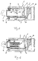
- FIG. 8 shows a reduced longitudinal section of the exhaust gas aftertreatment device 1 according to the invention, two SCR catalytic converters 9 being arranged below the mixing chamber 3, all of which communicate at one end with the collecting space 8 and at the other end with the second collecting space 11.
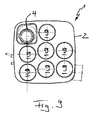
- the exhaust gas aftertreatment device 1 can be designed so that several, for example, seven SCR catalysts as shown in FIG. 9, parallel to each other and over- or are arranged side by side.
- the measurement of the NO x content is carried out downstream of the SCR catalysts 9, for example, just before a sound absorption chamber 20.
- the SCR catalysts 9 are all connected communicating with the collecting chamber 8 on the flow input side, while they all flow via the second plenum 11 are communicatively connected to the sound absorbing space 20.
- the SCR catalysts 9 are also conceivable.
Landscapes
- Engineering & Computer Science (AREA)
- Chemical & Material Sciences (AREA)
- Chemical Kinetics & Catalysis (AREA)
- Combustion & Propulsion (AREA)
- Mechanical Engineering (AREA)
- General Engineering & Computer Science (AREA)
- Health & Medical Sciences (AREA)
- Toxicology (AREA)
- Exhaust Gas After Treatment (AREA)
- Exhaust Gas Treatment By Means Of Catalyst (AREA)
Abstract
Description
Die vorliegende Erfindung betrifft eine Abgasnachbehandlungseinrichtung für eine Brennkraftmaschine, insbesondere in einem Kraftfahrzeug.The present invention relates to an exhaust aftertreatment device for an internal combustion engine, in particular in a motor vehicle.
Als selektives katalytisches Reduktionsverfahren (SCR-Verfahren), bezeichnet man eine selektive chemische Reaktion, bei der nicht alle Rauchgaskomponenten des Abgases reduziert werden, sondern nur deren Stickoxide. In der Fahrzeugtechnik wird dieses Verfahren zunehmend in Nutzfahrzeugen mit Dieselkraftstoffmotoren eingesetzt, um die Schadstoffemissionen so weit absenken zu können, damit diese die EU4-Norm erfüllen. Der für die Reduktion benötigte Ammoniak wird nicht direkt, das heißt in reiner Form zugegeben, sondern in Form einer wässrigen Harnstofflösung. Diese wird in den Abgasstrang eingespritzt und bewirkt durch eine Hydrolysereaktion eine Aufspaltung der Harnstoff-Wasserlösung in Ammoniak und Wasser. Der Vorteil des SCR-Verfahrens liegt in der Entfernung von Rußpartikeln und Stickoxiden aus dem Abgas und damit einer deutlich reduzierten Schadstoffemission. Nachteilig bei dem bisherigen Verfahren ist insbesondere, dass die Vermischung des Harnstoffes mit dem zu reinigenden Abgas oftmals nur unzufriedenstellend bewirkt werden kann.A selective catalytic reduction (SCR) process is a selective chemical reaction in which not all the flue gas components of the exhaust gas are reduced, only their nitrogen oxides. In vehicle technology, this method is increasingly being used in commercial vehicles with diesel engine engines in order to be able to reduce the pollutant emissions so far that they meet the EU4 standard. The ammonia required for the reduction is not added directly, that is in pure form, but in the form of an aqueous urea solution. This is injected into the exhaust system and causes by a hydrolysis reaction, a splitting of the urea-water solution into ammonia and water. The advantage of the SCR process lies in the removal of soot particles and nitrogen oxides from the exhaust gas and thus a significantly reduced pollutant emission. A disadvantage of the previous method is in particular that the mixing of the urea with the exhaust gas to be cleaned often can only be effected unsatisfactory.
Die vorliegende Erfindung beschäftigt sich mit dem Problem, für eine Abgasnachbehandlungseinrichtung der eingangs genannten Art eine verbesserte Ausführungsform anzugeben, die sich insbesondere durch eine verbesserte Vermischung eines Reduktionsmittels mit dem zu reinigenden Abgas auszeichnet.The present invention is concerned with the problem of providing for an exhaust aftertreatment device of the type mentioned in an improved embodiment, which is characterized in particular by an improved mixing of a reducing agent with the exhaust gas to be cleaned.
Dieses Problem wird erfindungsgemäß durch den Gegenstand des unabhängigen Anspruches gelöst. Vorteilhafte Ausführungsformen sind Gegenstand der abhängigen Ansprüche.This problem is solved according to the invention by the subject matter of the independent claim. Advantageous embodiments are the subject of the dependent claims.
Die Erfindung beruht auf dem allgemeinen Gedanken, einen zu reinigenden Abgasstrom in der Abgasnachbehandlungseinrichtung mehrfach umzulenken und dadurch eine besonders gute Durchmischung des Abgases mit dem zugesetzten Harnstoff zu erreichen. Hierzu weist die Abgasnachbehandlungseinrichtung ein Gehäuse auf, in welches ein in einer Mischkammer mündendes Rohr eindringt. Die Mischkammer ist topfförmig ausgebildet und so über die Mündung des Abgasrohres gestülpt, dass sich eine Strömungsrichtung von einströmendem Abgas umkehrt und das Abgas radial außerhalb des Abgasrohres zurückgeleitet wird. Ein offenes Ende der topfförmigen Mischkammer mündet dabei in einem Sammelraum, der vorzugsweise gasdicht ausgebildet ist, und dadurch das Abgas verlustfrei einem nachfolgenden SCR-Katalysator zuführen kann. Der Vorteil der erfindungsgemäßen Abgasnachbehandlungseinrichtung liegt dabei in der insgesamt 360° umfassenden Strömungsumkehr des Abgasstromes und damit einer besonders guten Durchmischung des zu reinigenden Abgases mit dem eingangs der Abgasnachbehandlungseinrichtung zugesetzten Harnstoff beziehungsweise Ammoniak. Die besonders gute Durchmischung bewirkt dabei wiederum eine nahezu vollständige Reduktion der Stickoxide.The invention is based on the general idea of repeatedly diverting an exhaust gas stream to be cleaned in the exhaust gas aftertreatment device and thereby achieving particularly thorough mixing of the exhaust gas with the added urea. For this purpose, the exhaust gas aftertreatment device has a housing into which a tube opening into a mixing chamber penetrates. The mixing chamber is cup-shaped and so slipped over the mouth of the exhaust pipe, that a flow direction of incoming exhaust gas reverses and the exhaust gas is returned radially outside of the exhaust pipe. An open end of the cup-shaped mixing chamber opens into a collecting space, which is preferably gas-tight, and thereby can supply the exhaust gas lossless a subsequent SCR catalyst. The advantage of the exhaust aftertreatment device according to the invention lies in the overall 360 ° flow reversal of the exhaust stream and thus a particularly good mixing of the exhaust gas to be cleaned with the beginning of the exhaust aftertreatment device added urea or ammonia. The particularly good mixing in turn causes an almost complete reduction of nitrogen oxides.
Zweckmäßig weist das Abgasrohr im Bereich seiner Mündung eine perforierte Wand auf. Derartige perforierte Wände bewirken größere Turbulenzen, welche im Vergleich zu einem nicht perforierten Abgasrohr eine verbesserte Durchmischung des Harnstoffs beziehungsweise des Reduktionsmittels mit dem zu reinigenden Abgas ergibt.The exhaust pipe expediently has a perforated wall in the region of its mouth. Such perforated walls cause greater turbulence, which results in an improved mixing of the urea or the reducing agent with the exhaust gas to be cleaned compared to a non-perforated exhaust pipe.
Bei einer vorteilhaften Ausführungsform der erfindungsgemäßen Lösung ist zumindest eines der nachfolgenden Strömungsleitelemente zwischen der Mischkammer und dem Sammelraum angeordnet: Lochboden, Spin-Element, Drallelement. Die aufgeführten Elemente bewirken alle eine Ab- beziehungsweise Umlenkung des Abgasstroms und damit eine zusätzliche Durchmischung des Abgases. Es ist dabei selbstverständlich, dass die genannten Elemente entweder einzeln oder in beliebiger Kombination miteinander in der erfindungsgemäßen Abgasnachbehandlungseinrichtung zum Einsatz kommen können.In an advantageous embodiment of the solution according to the invention, at least one of the following flow guide elements is arranged between the mixing chamber and the collecting space: perforated bottom, spin element, swirl element. The listed elements all cause a diversion or deflection of the exhaust gas flow and thus an additional mixing of the exhaust gas. It goes without saying that the elements mentioned can be used either individually or in any combination with one another in the exhaust aftertreatment device according to the invention.
Bei einer weiteren vorteilhaften Ausführungsform der erfindungsgemäßen Lösung ist stromab des SCR-Katalysators ein Schallabsorptionsraum angeordnet. Nach der katalytischen Reaktion im SCR-Katalysator, das heißt nach der Reduktion der Stickoxide, wird somit der Abgasstrom dem Schallabsorptionsraum zugeleitet, welcher, beispielsweise durch eine entsprechende Auskleidung, eine Schallabsorption und damit eine Reduzierung der Schallemission bewirkt. Die Abgasnachbehandlungseinrichtung erfüllt somit nicht nur den Zweck der Reinigung des Abgases, sondern zugleich auch die Funktion eines Schalldämpfers, wodurch eine besonders kompakte Bauweise erreicht werden kann.In a further advantageous embodiment of the solution according to the invention, a sound absorption space is arranged downstream of the SCR catalyst. After the catalytic reaction in the SCR catalyst, that is, after the reduction of the nitrogen oxides, the exhaust gas flow is thus supplied to the sound absorption space, which, for example, by a corresponding lining, a sound absorption and thus a reduction the sound emission causes. The exhaust aftertreatment device thus fulfills not only the purpose of cleaning the exhaust gas, but at the same time also the function of a silencer, whereby a particularly compact construction can be achieved.
Zweckmäßig ist stromab des SCR-Katalysators ein Nox-Sensor angeordnet. Ein derartiger Nox-Sensor misst den im aus dem SCR-Katalysator ausströmenden Abgas enthaltenen Nox-Gehalt und leitet diesen Wert an eine Auswerteeinrichtung weiter, welche den detektierten Wert mit einem vorgeschriebenen Soll-Wert vergleicht. Des weiteren ist vorstellbar, dass entsprechend einer Abweichung zwischen gemessenem Ist-Wert und vorgegebenem Soll-Wert die Harnstoffzufuhr und dadurch der Reduktionsprozess geregelt wird.Expediently, a No x sensor is arranged downstream of the SCR catalytic converter. Such a No x sensor measures the NO x content contained in the exhaust gas flowing out of the SCR catalytic converter and forwards this value to an evaluation device which compares the detected value with a prescribed desired value. Furthermore, it is conceivable that the urea supply and thus the reduction process are regulated in accordance with a deviation between the measured actual value and the predetermined desired value.
Weitere wichtige Merkmale und Vorteile der Erfindung ergeben sich aus den Unteransprüchen, aus den Zeichnungen und aus der zugehörigen Figurenbeschreibung anhand der Zeichnungen.Other important features and advantages of the invention will become apparent from the dependent claims, from the drawings and from the associated figure description with reference to the drawings.
Es versteht sich, dass die vorstehend genannten und die nachstehend noch zu erläuternden Merkmale nicht nur in der jeweils angegebenen Kombination, sondern auch in anderen Kombinationen oder in Alleinstellung verwendbar sind, ohne den Rahmen der vorliegenden Erfindung zu verlassen.It is understood that the features mentioned above and those yet to be explained below can be used not only in the particular combination given, but also in other combinations or in isolation, without departing from the scope of the present invention.
Bevorzugte Ausführungsbeispiele der Erfindung sind in den Zeichnungen dargestellt und werden in der nachfolgenden Beschreibung näher erläutert, wobei sich gleiche Bezugszeichen auf gleiche oder ähnliche oder funktional gleiche Bauteile beziehen.Preferred embodiments of the invention are illustrated in the drawings and will be explained in more detail in the following description, wherein like reference numerals refer to the same or similar or functionally identical components.
Es zeigen, jeweils schematisch,
- Fig. 1
- einen Längsschnitt durch eine Abgasnachbehandlungseinrichtung im Bereich eines Abgasrohres,
- Fig. 2
- eine Darstellung wie in Fig. 1, jedoch mit einem anderen Abgasrohr,
- Fig. 3
- eine Darstellung wie in Fig. 2, jedoch mit einem weiteren Abgasrohr,
- Fig. 4
- eine Darstellung wie in Fig. 3, jedoch mit einem endseitig verschlossenen Abgasrohr,
- Fig. 5
- eine Darstellung wie in Fig. 4, jedoch mit im Bereich einer Mündung perforierten Wandung des Abgasrohres,
- Fig. 6
- eine Darstellung wie in Fig. 5, jedoch mit einem endseitig offenen Abgasrohr,
- Fig. 7
- einen Längsschnitt durch ein Abgasrohr mit einer Venturidüse,
- Fig. 8
- einen Längsschnitt durch die Abgasnachbehandlungseinrichtung wie in Fig. 2, jedoch mit mehreren SCR-Katalysatoren,
- Fig. 9
- einen Querschnitt durch die Abgasnachbehandlungseinrichtung entlang der Linie IX-IX.
- Fig. 1
- a longitudinal section through an exhaust gas aftertreatment device in the region of an exhaust pipe,
- Fig. 2
- a representation as in Fig. 1, but with a different exhaust pipe,
- Fig. 3
- a representation as in Fig. 2, but with a further exhaust pipe,
- Fig. 4
- a representation as in Fig. 3, but with an end closed exhaust pipe,
- Fig. 5
- a representation as in Fig. 4, but with perforated in the region of an orifice wall of the exhaust pipe,
- Fig. 6
- a representation as in Fig. 5, but with an open end exhaust pipe,
- Fig. 7
- a longitudinal section through an exhaust pipe with a venturi,
- Fig. 8
- a longitudinal section through the exhaust aftertreatment device as in FIG. 2, but with several SCR catalysts,
- Fig. 9
- a cross section through the exhaust aftertreatment device along the line IX-IX.
Entsprechend Fig. 1 weist eine erfindungsgemäße Abgasnachbehandlungseinrichtung 1 für eine nicht gezeigte Brennkraftmaschine ein Gehäuse 2 auf, in welches ein in einer Mischkammer 3 mündendes Abgasrohr 4 eindringt. Dabei ist die Mischkammer 3 topfförmig ausgebildet und weist in allen Ausführungsformen einen gewölbten Prallboden 5 auf. Dieser Prallboden 5 kann beispielsweise eine Sintermetallplatte aufweisen oder als solche ausgebildet sein. Die Mischkammer 3 dient zum gründlichen Durchmischen des in die Abgasnachbehandlungseinrichtung 1 einströmenden Abgases, welchem zuvor ein Reduktionsmittel, beispielsweise Harnstoff, zugeführt wird. Für eine erfolgreiche Entfernung der in dem Abgas vorhandenen Stickoxide muss das Abgas vorzugsweise homogen mit dem Reduktionsmittel, also beispielsweise dem Harnstoff, vermischt werden. Wie in Fig. 1 gezeigt, strömt das Abgas entlang der Strömungspfeile 6 von links nach rechts durch das Abgasrohr 4 in die Mischkammer 3 ein. Die topfförmige Ausbildung der Mischkammer 3 bewirkt, dass das einströmende Abgas seine Strömungsrichtung umkehrt und radial außerhalb des Abgasrohres 4, das heißt von rechts nach links, zurückströmt. In einem linken Bereich, das heißt einem offenen Ende 7, der topfförmigen Mischkammer 3 angekommen, strömt das Abgas in einen Sammelraum 8, welcher das Abgas einem nachfolgenden SCR-Katalysator 9 zuführt. Der Sammelraum 8 ist gasdicht ausgebildet, so dass das von der Mischkammer 3 in den Sammelraum 8 geströmte Abgas vorzugsweise verlustfrei dem SCR-Katalysator 9 zugeführt werden kann.1, an exhaust gas aftertreatment device 1 according to the invention for a combustion engine, not shown, on a
Radial außerhalb des Abgasrohres 4 bildet sich gemäß den Fig. 1 bis 6 ein sogenannter Rückstromringraum 10, in welchem das Abgas mit um 180° umgekehrter Strömungsrichtung 6 zum offenen Ende 7 der Mischkammer 3 strömt. Allen Darstellungen in den Fig. 1 bis 6 ist dabei gemein, dass der für die Reduktion der Stickoxide verantwortliche SCR-Katalysator 9 nur teilweise dargestellt ist.Radially outside of the
Stromab des SCR-Katalysators 9 ist vorzugsweise ein zweiter Sammelraum 11 angeordnet, in welchem sich das Abgas sammelt und von dort einem Schallabsorptionsraum 20 zugeführt wird, in welchem beispielsweise ein Akustikfilter und/oder ein Teilchenfilter angeordnet ist. Ebenfalls stromab des SCR-Katalysators 9 ist ein Nox-Sensor 12 vorgesehen, welcher den im gereinigten Abgasstrom enthaltenen Stickoxidanteil misst und an eine nicht gezeigte Auswerte- und Steuereinrichtung weiterleitet. Die Auswerte- und Steuereinrichtung vergleicht dann den gemessenen Nox-Ist-Wert mit einem vorgegebenen Nox-Soll-Wert und steuert gegebenenfalls den Harnstoffanteil nach. Denkbar ist auch, dass bei einem Überschreiten eines Nox-Grenzwertes Maßnahmen, wie beispielsweise das Aufleuchten einer Kontrolllampe oder eine Drehmomentenreduzierung eingeleitet werden.Downstream of the SCR catalytic converter 9, a second collecting chamber 11 is preferably arranged, in which the exhaust gas collects and from there is supplied to a
Generell ist vorgesehen, dass die Abgasnachbehandlungseinrichtung 1 möglichst motornah angeordnet ist. Ebenso können mehrere SCR-Katalysatoren 9 parallel zueinander angeordnet werden, die vorzugsweise alle vom gemeinsamen Sammelraum 8 aus mit Abgas beliefert werden. Diese weiteren, lediglich in den Fig. 8 und 9 dargestellten SCR-Katalysatoren 9, könnten beispielsweise in den Fig. 1 bis 6 parallel unter dem dort jeweils eingezeichneten SCR-Katalysator 9 angeordnet sein.In general, it is provided that the exhaust gas aftertreatment device 1 is arranged as close as possible to the engine. Likewise, a plurality of SCR catalysts 9 can be arranged parallel to one another, which are preferably all supplied with exhaust gas from the
In Abwandlung zu Fig. 1 ist auch vorstellbar, dass das Abgasrohr 4 mit seiner Mündung deutlich weniger in die Mischkammer 3 hineinreicht, und beispielsweise bereits im Bereich einer unterbrochen gezeichneten Linie 13 endet.In a modification to Fig. 1 is also conceivable that the
Im Folgenden sollen nun unterschiedliche Formen von Mündungsbereichen der Abgasrohre 4 in den Fig. 2 bis 6 näher erläutert werden:
- Fig. 2 zeigt
ein Abgasrohr 4, dessen Wandung im Bereich der Mischkammer 3 radial nach innen verjüngt ausgeführt ist und im Bereich der Verjüngung perforiert ist. Hierdurch strömt Abgas durch die Perforation radial nach außen und tritt danach gemäßden Strömungspfeilen 6 indie Mischkammer 3 ein. Die Perforation dient dabei ebenfalls zur Unterstützung des Mischungsprozess zwischen Abgas und Reduktionsmittel. - Fig. 3 zeigt ein ebenfalls im Bereich der Mischkammer 3 verjüngtes und in dem verjüngten Bereich perforiertes Abgasrohr 4, wobei im Vergleich zu Fig. 2 eine perforierte Längserstreckung deutlich kleiner gewählt ist. Der Strömungsverlauf erfolgt dabei in nahezu analoger Weise zu Fig. 2, das heißt das Abgas
verlässt das Abgasrohr 4 durch dessen axial endseitig angeordnete Öffnung. Um die Durchmischung zwischen dem Reduktionsmittel und dem Abgas zusätzlich zu fördern,können im Rückstromringraum 10 oder inder Mischkammer 3Strömungsleitelemente 18, wie beispielsweise ein Lochboden, ein Spin-Element oder ein Drallelement angeordnet sein. Denkbar ist, auch, dass die topfförmige Mischkammer 3 entlang des Rückstromringraumes 10 eine Dralleinrichtung in der Art eines perforierten Schneckenganges 19 aufweist.
- Fig. 2 shows an
exhaust pipe 4, the wall of which is designed to taper radially inwardly in the region of the mixingchamber 3 and is perforated in the region of the taper. As a result, exhaust gas flows radially outwards through the perforation and then enters the mixingchamber 3 according to theflow arrows 6. The perforation also serves to support the mixing process between exhaust gas and reducing agent. - FIG. 3 shows an
exhaust pipe 4 which is also tapered in the region of the mixingchamber 3 and perforated in the tapered region, a perforated longitudinal extension being shown in FIG. 2 much smaller. The flow path takes place in an almost analogous manner to FIG. 2, that is, the exhaust gas leaves theexhaust pipe 4 through its axially arranged end opening. In order to additionally promote the mixing between the reducing agent and the exhaust gas, flowguide elements 18, such as, for example, a perforated bottom, a spin element or a swirl element, can be arranged in thereturn flow annulus 10 or in the mixingchamber 3. It is also conceivable that the cup-shapedmixing chamber 3 along theRückstromringraumes 10 has a twisting device in the manner of aperforated screw thread 19.
In Fig. 4 ist ein Abgasrohr 4 gezeigt, welches einen ähnlich perforierten Bereich in der Mischkammer 3 aufweist, wie das Abgasrohr in Fig. 3, wobei hier das Abgas das Abgasrohr 4 jedoch nicht in axialer Richtung stirnseitig verlässt, sondern durch im Mündungsbereich bzw. der Wandung des Abgasrohres 4 vorgesehene Öffnungen 14.In Fig. 4, an
In Fig. 5 ist ein Endbereich des Abgasrohres 4 dargestellt, welcher axial endseitig durch einen Boden 15 verschlossen ist und nahe am axialen Ende des Abgasrohres 4 in der Mischkammer 3 in radialer Richtung durch die Wandung des Abgasrohres 4 durchgehende Öffnungen 14' aufweist.In Fig. 5, an end portion of the
In Fig. 6 weist der Endbereich des Abgasrohres 4 einen axialen Durchlass sowie in der Wandung des Abgasrohres 4 angebrachte Öffnungen 14" auf. Hierdurch kann das Abgas das Abgasrohr 4 sowohl in axialer als auch in radialer Richtung verlassen, wodurch eine besonders gute Durchmischung in der Mischkammer 3 erzielt werden kann. Die Öffnungen 14" liegen dabei gemäß Fig. 6 auf einer Achse 16 des Abgasrohres 4, wobei auch denkbar ist, dass die Öffnungen 14" in anderer Weise in der Wandung des Abgasrohres 4 angeordnet sind. Durch den Umstand, dass das Abgasrohr 4 mischkammerseitig schräg endet, wird der Mischvorgang in der Mischkammer 3 zusätzlich unterstützt.6, the end region of the
Zusätzlich oder alternativ zu den in den Fig. 1 bis 6 dargestellten Endbereichen des Abgasrohres 4, kann das Abgasrohr 4 auch wie in Fig. 7 gezeigt als Venturidüse ausgebildet sein oder einen als Venturidüse ausgebildeten Einsatz 17 aufweisen. In einer derartigen Venturidüse wird ohne zusätzliche aktive Einwirkung ein Unterdruck und eine Erhöhung der Strömungsgeschwindigkeit an der engsten Stelle des Abgasrohres 4 erzeugt. Nach dem Passieren der engsten Stelle sind am Einsatz 17 gemäß Fig. 7 ebenfalls Öffnungen 14" angeordnet, welche eine Durchmischung des Reduktionsmittels mit dem Abgasstrom zusätzlich fördern.In addition or as an alternative to the end regions of the
In Fig. 8 ist ein verkleinerter Längsschnitt der erfindungsgemäßen Abgasnachbehandlungseinrichtung 1 gezeigt, wobei unter der Mischkammer 3 zwei SCR-Katalysatoren 9 angeordnet sind, welche alle einenends mit dem Sammelraum 8 und anderenends mit dem zweiten Sammelraum 11 kommunizieren. Dabei kann die Abgasnachbehandlungseinrichtung 1 so ausgebildet sein, dass mehrere, beispielsweise sieben SCR-Katalysatoren wie in Fig. 9 gezeigt, parallel zueinander und über- bzw. nebeneinander angeordnet sind. Die Messung des NOx-Gehaltes erfolgt dabei stromab der SCR-Katalysatoren 9, beispielsweise kurz vor einem Schallabsorptionsraum 20. Dabei sind wie oben erwähnt die SCR-Katalysatoren 9 strömungseingangsseitig alle kommunizierend mit dem Sammelraum 8 verbunden, während sie strömungsausgangsseitig alle über den zweiten Sammelraum 11 mit dem Schallabsorptionsraum 20 kommunizierend verbunden sind. Denkbar sind selbstverständlich auch andere, insbesondere eine größere Anzahl an SCR-Katalysatoren 9.FIG. 8 shows a reduced longitudinal section of the exhaust gas aftertreatment device 1 according to the invention, two SCR catalytic converters 9 being arranged below the mixing
Claims (10)
dadurch gekennzeichnet,
dass das Abgasrohr (4) als Venturidüse ausgebildet ist oder einen als Venturidüse ausgebildeten Einsatz (17) aufweist.Exhaust after-treatment device according to claim 1,
characterized,
that the exhaust pipe (4) is designed as a venturi nozzle or a venturi nozzle designed as insert (17).
dadurch gekennzeichnet,
characterized,
dadurch gekennzeichnet,
dass das Abgasrohr (4) im Bereich seiner Mündung eine perforierte Wand aufweist.Exhaust after-treatment device according to one of claims 1 to 3,
characterized,
that the exhaust pipe (4) has a perforated wall in the region of its mouth.
dadurch gekennzeichnet,
dass zwischen der Mischkammer (3) und dem Sammelraum (8) zumindest eines der folgenden Strömungsleitelemente (18) angeordnet ist: Lochboden, Spin-Element, Drallelement.Exhaust after-treatment device according to one of claims 1 to 4,
characterized,
in that at least one of the following flow guide elements (18) is arranged between the mixing chamber (3) and the collecting space (8): perforated bottom, spin element, swirl element.
dadurch gekennzeichnet,
dass die topfförmige Mischkammer (3) eine Dralleinrichtung in der Art eines perforierten Schneckengangs (19) aufweist.Exhaust after-treatment device according to one of claims 1 to 5,
characterized,
in that the pot-shaped mixing chamber (3) has a swirling device in the manner of a perforated screw flight (19).
dadurch gekennzeichnet,
dass stromab des SCR-Katalysators (9) ein Schallabsorptionsraum (20) angeordnet ist.Exhaust after-treatment device according to one of claims 1 to 6,
characterized,
in that a sound absorption space (20) is arranged downstream of the SCR catalytic converter (9).
dadurch gekennzeichnet,
dass im Schallabsorptionsraum (20) ein Akustikfilter
und/oder ein Teilchenfilter angeordnet ist.Exhaust after-treatment device according to claim 7,
characterized,
that in the sound absorption chamber (20), an acoustic filter
and / or a particle filter is arranged.
dadurch gekennzeichnet,
dass die Abgasnachbehandlungseinrichtung (1) motornah angeordnet ist.Exhaust after-treatment device according to one of claims 1 to 8,
characterized,
that the exhaust gas treatment device (1) is arranged close to the engine.
dadurch gekennzeichnet,
dass stromab des SCR-Katalysators (9) ein NOx-Sensor (12) angeordnet ist.Exhaust after-treatment device according to one of claims 1 to 9,
characterized,
in that an NO x sensor (12) is arranged downstream of the SCR catalytic converter (9).
Applications Claiming Priority (1)
| Application Number | Priority Date | Filing Date | Title |
|---|---|---|---|
| DE102006023854A DE102006023854B4 (en) | 2006-05-19 | 2006-05-19 | Exhaust after-treatment device for an internal combustion engine |
Publications (3)
| Publication Number | Publication Date |
|---|---|
| EP1857651A2 true EP1857651A2 (en) | 2007-11-21 |
| EP1857651A3 EP1857651A3 (en) | 2008-05-21 |
| EP1857651B1 EP1857651B1 (en) | 2013-06-19 |
Family
ID=38375625
Family Applications (1)
| Application Number | Title | Priority Date | Filing Date |
|---|---|---|---|
| EP07104112.3A Active EP1857651B1 (en) | 2006-05-19 | 2007-03-14 | Exhaust gas treating device for an internal combustion engine |
Country Status (5)
| Country | Link |
|---|---|
| US (1) | US8220253B2 (en) |
| EP (1) | EP1857651B1 (en) |
| JP (1) | JP5081496B2 (en) |
| CN (1) | CN101074620B (en) |
| DE (1) | DE102006023854B4 (en) |
Cited By (4)
| Publication number | Priority date | Publication date | Assignee | Title |
|---|---|---|---|---|
| WO2009106123A1 (en) * | 2008-02-25 | 2009-09-03 | Eugen Seitz Ag | Silencer for valve equipment for blow-moulding machines |
| DE102009014800A1 (en) | 2009-03-25 | 2010-09-30 | Webasto Ag | Convertible top system for motor vehicle, has interlocking unit carrying out horizontal displacement through articulation mechanism in order to allow opening and closing of system, where mechanism is composed of multiple articulations |
| CN105275554A (en) * | 2015-10-21 | 2016-01-27 | 西安交通大学 | SCR post-treatment device with exhaust mixer |
| EP3327261A1 (en) * | 2016-11-25 | 2018-05-30 | Eberspächer Exhaust Technology GmbH & Co. KG | Exhaust gas treatment assembly |
Families Citing this family (40)
| Publication number | Priority date | Publication date | Assignee | Title |
|---|---|---|---|---|
| US20080041043A1 (en) * | 2006-08-16 | 2008-02-21 | Andersen Eric H | Exhaust treatment devices and methods for reducing sound using the exhaust treatment devices |
| US20100139258A1 (en) * | 2008-12-04 | 2010-06-10 | Caterpillar Inc. | Exhaust mixer with backward flow |
| DE102009014433A1 (en) | 2009-03-26 | 2010-09-30 | J. Eberspächer GmbH & Co. KG | Exhaust gas treatment device |
| DE102009014435A1 (en) | 2009-03-26 | 2010-10-14 | J. Eberspächer GmbH & Co. KG | Exhaust gas treatment device |
| DE102010014037A1 (en) * | 2009-04-02 | 2010-11-04 | Cummins Filtration IP, Inc., Minneapolis | Reducing agent i.e. urea, decomposition system, has reducing agent injector coupled with exhaust chamber, where reducing agent injector is fixed in reducing agent injection connection part with exhaust gas in exhaust chamber |
| US8460610B2 (en) * | 2009-12-22 | 2013-06-11 | Caterpillar Inc. | Canister aftertreatment module |
| US8596049B2 (en) * | 2009-12-22 | 2013-12-03 | Caterpillar Inc. | Exhaust system having an aftertreatment module |
| DE102010008999A1 (en) * | 2010-02-24 | 2011-08-25 | J. Eberspächer GmbH & Co. KG, 73730 | Exhaust gas treatment device |
| US8661795B2 (en) * | 2010-03-09 | 2014-03-04 | Mtd Products Inc | Exhaust system having multiple inlets and multiple outlets |
| US8393147B2 (en) | 2010-06-30 | 2013-03-12 | Caterpillar Inc. | Exhaust system having an aftertreatment module |
| CN102155276A (en) * | 2011-01-26 | 2011-08-17 | 烟台华龙商用机器有限公司 | Tail gas emission purification system of diesel engine |
| US8609030B2 (en) | 2011-03-04 | 2013-12-17 | Tenneco Automotive Operating Company Inc. | Exhaust aftertreatment device with integrated shell and baffle |
| US8776509B2 (en) * | 2011-03-09 | 2014-07-15 | Tenneco Automotive Operating Company Inc. | Tri-flow exhaust treatment device with reductant mixing tube |
| DE102011015512A1 (en) * | 2011-03-30 | 2012-10-04 | Dif Die Ideenfabrik Gmbh | Compact exhaust treatment unit with mixing zone and method for mixing an exhaust gas |
| CN102536399A (en) * | 2011-12-31 | 2012-07-04 | 杭州银轮科技有限公司 | SCR (Selective Catalytic Reduction) catalytic converter for post treatment of tail gas of diesel engine |
| GB201207201D0 (en) * | 2012-04-24 | 2012-06-06 | Perkins Engines Co Ltd | Emissions cleaning module for a diesel engine |
| EP2671630B1 (en) | 2012-06-07 | 2016-08-10 | General Electric Company | Mixing device having a plurality of mixing channels and use thereof |
| US9267413B2 (en) | 2012-06-20 | 2016-02-23 | Cnh Industrial America Llc | Exhaust system for an agricultural vehicle |
| CN102817672A (en) * | 2012-09-12 | 2012-12-12 | 大连新飞船机有限公司 | Pneumatic motor silencing and dirt collecting device |
| US20140199771A1 (en) * | 2013-01-17 | 2014-07-17 | Miratech Holdings, Llc | METHOD AND APPARATUS FOR ANALYSIS AND SELECTIVE CATALYTIC REDUCTION OF NOx-CONTAINING GAS STREAMS |
| DE102013210799C5 (en) * | 2013-06-10 | 2020-07-09 | Eberspächer Exhaust Technology GmbH & Co. KG | Exhaust system of an internal combustion engine |
| DE102013108745A1 (en) * | 2013-08-13 | 2015-02-19 | Emitec Gesellschaft Für Emissionstechnologie Mbh | Exhaust gas treatment unit |
| CN104747256A (en) * | 2013-12-27 | 2015-07-01 | 陕西汽车集团有限责任公司 | Urea mixer in exhaust gas emission system of diesel car |
| CN104121081B (en) * | 2014-07-02 | 2017-10-03 | 潍柴动力股份有限公司 | A kind of air inlet pipe of SCR exhaust treatment systems, SCR exhaust treatment systems |
| US11585253B2 (en) | 2015-08-07 | 2023-02-21 | Cummins Emission Solutions Inc. | Converging liquid reductant injector nozzle in selective catalytic reduction systems |
| KR102520281B1 (en) * | 2015-09-30 | 2023-04-12 | 로베르트 보쉬 게엠베하 | Swirl Mixed Exhaust Gas Aftertreatment Box and System |
| US10100702B2 (en) * | 2016-07-19 | 2018-10-16 | Ford Global Technologies, Llc | Method and system for exhaust particulate matter sensing |
| US11136910B2 (en) | 2017-06-06 | 2021-10-05 | Cummins Emission Solutions Inc. | Systems and methods for mixing exhaust gases and reductant in an aftertreatment system |
| CN107559082A (en) * | 2017-10-10 | 2018-01-09 | 广西玉柴机器股份有限公司 | Diesel engine after treatment device |
| US10563557B2 (en) | 2017-12-20 | 2020-02-18 | Cnh Industrial America Llc | Exhaust system for a work vehicle |
| US10273854B1 (en) | 2017-12-20 | 2019-04-30 | Cnh Industrial America Llc | Exhaust system for a work vehicle |
| GB2603883B (en) | 2018-04-02 | 2022-11-23 | Cummins Emission Solutions Inc | Aftertreatment system including noise reducing components |
| US11486289B2 (en) | 2018-07-03 | 2022-11-01 | Cummins Emission Solutions Inc. | Body mixing decomposition reactor |
| US11242782B2 (en) * | 2019-01-31 | 2022-02-08 | R&R Holding & Leasing | Muffler |
| US10865683B2 (en) * | 2019-03-20 | 2020-12-15 | Caterpillar Inc. | Aftertreatment module |
| US11187128B2 (en) * | 2020-03-09 | 2021-11-30 | Progress Rail Services Corporation | After-treatment system for repower locomotives |
| US20230304432A1 (en) * | 2020-10-22 | 2023-09-28 | Cummins Emission Solutions Inc. | Exhaust gas aftertreatment system |
| CN114412622B (en) * | 2022-03-29 | 2022-06-17 | 天津内燃机研究所(天津摩托车技术中心) | Vehicle tail gas purification device |
| USD1042544S1 (en) | 2022-04-21 | 2024-09-17 | Cummins Emission Solutions Inc. | Aftertreatment system |
| USD1042545S1 (en) | 2022-04-21 | 2024-09-17 | Cummins Emission Solutions Inc. | Aftertreatment system |
Family Cites Families (24)
| Publication number | Priority date | Publication date | Assignee | Title |
|---|---|---|---|---|
| US3235003A (en) * | 1963-06-04 | 1966-02-15 | Cloyd D Smith | Spiral flow baffle system |
| US3736105A (en) * | 1971-10-06 | 1973-05-29 | J F Tourtellotte | Catalytic muffler |
| JPS5246219A (en) * | 1975-10-09 | 1977-04-12 | Honda Motor Co Ltd | Exhaust gas recombustion system for internal-combustion engine |
| JPS5973478A (en) * | 1982-10-18 | 1984-04-25 | 日本特殊陶業株式会社 | Ceramic honeycomb and manufacture |
| JPS60184919A (en) * | 1984-03-01 | 1985-09-20 | Nissan Motor Co Ltd | Catalytic muffler for internal-combustion engine |
| US4595073A (en) * | 1984-05-14 | 1986-06-17 | Nelson Industries Inc. | Plug-type muffler section |
| JP2516656B2 (en) * | 1988-03-09 | 1996-07-24 | 三菱重工業株式会社 | Denitration reactor |
| US5376341A (en) * | 1992-07-24 | 1994-12-27 | Corning Incorporated | Catalytic converter for motorcycles |
| DK57996A (en) * | 1996-05-15 | 1997-11-16 | Silentor As | Muffler |
| US6183689B1 (en) * | 1997-11-25 | 2001-02-06 | Penn State Research Foundation | Process for sintering powder metal components |
| ES2174642T3 (en) * | 1998-08-11 | 2002-11-01 | Siemens Ag | DEVICE FOR CATALITIC CLEANING OF EXHAUST GAS. |
| US7282185B2 (en) * | 1999-01-11 | 2007-10-16 | Clean Air Power, Inc. | Emission control apparatus |
| AU1870901A (en) * | 1999-12-09 | 2001-06-18 | Eminox Limited | Apparatus |
| JP2001234735A (en) * | 2000-02-24 | 2001-08-31 | Meidensha Corp | Flow control device |
| ATE338198T1 (en) * | 2000-03-21 | 2006-09-15 | Silentor Holding As | SILENCER HAVING ONE OR MORE POROUS BODY |
| JP4445137B2 (en) * | 2001-01-12 | 2010-04-07 | 株式会社小松製作所 | Engine exhaust purification structure |
| CN1176299C (en) * | 2002-03-28 | 2004-11-17 | 天津大学 | Catalytic cleaner matching method for motorcycle |
| JP2003293739A (en) * | 2002-04-02 | 2003-10-15 | Mitsubishi Fuso Truck & Bus Corp | NOx CLEANING DEVICE FOR INTERNAL COMBUSTION ENGINE |
| DE10329000A1 (en) | 2003-06-27 | 2005-01-27 | Emitec Gesellschaft Für Emissionstechnologie Mbh | Exhaust gas aftertreatment system with a countercurrent housing, as well as a corresponding procedure for exhaust aftertreatment |
| DE10340105A1 (en) * | 2003-08-30 | 2005-03-24 | Man Nutzfahrzeuge Ag | Exhaust line of an internal combustion engine with built-in pre and main silencer |
| CN2709657Y (en) * | 2003-09-16 | 2005-07-13 | 王承东 | Secondary purification silencer for tail gas of vehicle |
| US6925796B2 (en) * | 2003-11-19 | 2005-08-09 | Ford Global Technologies, Llc | Diagnosis of a urea SCR catalytic system |
| US7246680B2 (en) * | 2004-07-01 | 2007-07-24 | General Motors Corporation | Sound dampening assembly for automotive exhaust system |
| US7279022B2 (en) * | 2005-01-24 | 2007-10-09 | Industrial Widget Works Company | Spiraltrap: devices and methods for the trapping particulate matter in exhaust and of other pollutants |
-
2006
- 2006-05-19 DE DE102006023854A patent/DE102006023854B4/en active Active
-
2007
- 2007-03-14 EP EP07104112.3A patent/EP1857651B1/en active Active
- 2007-05-17 JP JP2007131219A patent/JP5081496B2/en active Active
- 2007-05-18 US US11/804,716 patent/US8220253B2/en active Active
- 2007-05-18 CN CN2007101070868A patent/CN101074620B/en active Active
Non-Patent Citations (1)
| Title |
|---|
| None |
Cited By (5)
| Publication number | Priority date | Publication date | Assignee | Title |
|---|---|---|---|---|
| WO2009106123A1 (en) * | 2008-02-25 | 2009-09-03 | Eugen Seitz Ag | Silencer for valve equipment for blow-moulding machines |
| DE102009014800A1 (en) | 2009-03-25 | 2010-09-30 | Webasto Ag | Convertible top system for motor vehicle, has interlocking unit carrying out horizontal displacement through articulation mechanism in order to allow opening and closing of system, where mechanism is composed of multiple articulations |
| CN105275554A (en) * | 2015-10-21 | 2016-01-27 | 西安交通大学 | SCR post-treatment device with exhaust mixer |
| EP3327261A1 (en) * | 2016-11-25 | 2018-05-30 | Eberspächer Exhaust Technology GmbH & Co. KG | Exhaust gas treatment assembly |
| US10113472B2 (en) | 2016-11-25 | 2018-10-30 | Eberspächer Exhaust Technology GmbH & Co. KG | Exhaust gas treatment device |
Also Published As
| Publication number | Publication date |
|---|---|
| DE102006023854B4 (en) | 2008-03-27 |
| DE102006023854A1 (en) | 2007-11-22 |
| JP5081496B2 (en) | 2012-11-28 |
| JP2007309322A (en) | 2007-11-29 |
| EP1857651B1 (en) | 2013-06-19 |
| CN101074620A (en) | 2007-11-21 |
| CN101074620B (en) | 2011-12-07 |
| US20070289294A1 (en) | 2007-12-20 |
| US8220253B2 (en) | 2012-07-17 |
| EP1857651A3 (en) | 2008-05-21 |
Similar Documents
| Publication | Publication Date | Title |
|---|---|---|
| EP1857651B1 (en) | Exhaust gas treating device for an internal combustion engine | |
| EP2598730B1 (en) | Apparatus for exhaust gas treatment | |
| EP1556587B1 (en) | Exhaust gas aftertreatment system, especially for a diesel engine | |
| DE102011051875B4 (en) | DOSING MODULE FOR A VEHICLE EXHAUST TREATMENT SYSTEM | |
| EP2101049B1 (en) | Compact exhaust gas after treatment system | |
| EP1953359B1 (en) | Exhaust system for an internal combustion engine | |
| EP1536877B1 (en) | Method for the post-treatment of exhaust gases and device therefor | |
| EP2161423B1 (en) | Exhaust gas facility for diesel vehicles with an SCR catalytic converter | |
| DE102011077156B4 (en) | Exhaust system and injection module | |
| DE10218255B4 (en) | Exhaust system for a diesel engine and associated silencer | |
| EP3443209B1 (en) | Exhaust-gas aftertreatment device with catalytic converter and mixing device | |
| DE102009053950A1 (en) | Device for aftertreatment of exhaust gases of internal combustion engines | |
| DE202008001547U1 (en) | Assembly for introducing a reducing agent into the exhaust pipe of an exhaust system of an internal combustion engine | |
| EP2826971A1 (en) | Method for reducing nitrogen oxides in diesel engine exhaust gases and exhaust gas treatment system for carrying out the method | |
| DE102007035226A1 (en) | Flow guiding device and thus equipped exhaust system | |
| EP3196434B1 (en) | Scr waste gas treatment assembly | |
| EP2610457A1 (en) | Exhaust gas treatment device | |
| DE102020127384A1 (en) | SAMPLING DEVICE FOR AN EXHAUST GAS SENSOR | |
| EP3704360B1 (en) | Exhaust gas system for compact and efficient aftertreatment and sound damping of the exhaust gas | |
| DE10300408A1 (en) | Fluid treatment method and honeycomb body | |
| DE102014217844A1 (en) | Exhaust treatment plant for an internal combustion engine and internal combustion engine | |
| DE102008022998B4 (en) | Apparatus and method for purifying exhaust gases for an exhaust line of an internal combustion engine | |
| EP2325450A1 (en) | Device for treating exhaust gases of a combustion engine | |
| DE102019126578A1 (en) | Technology for the homogenization of exhaust gas mixtures | |
| DE102015226039A1 (en) | Particulate filter for an exhaust aftertreatment system, exhaust aftertreatment system and method of making a particulate filter |
Legal Events
| Date | Code | Title | Description |
|---|---|---|---|
| PUAI | Public reference made under article 153(3) epc to a published international application that has entered the european phase |
Free format text: ORIGINAL CODE: 0009012 |
|
| AK | Designated contracting states |
Kind code of ref document: A2 Designated state(s): AT BE BG CH CY CZ DE DK EE ES FI FR GB GR HU IE IS IT LI LT LU LV MC MT NL PL PT RO SE SI SK TR |
|
| AX | Request for extension of the european patent |
Extension state: AL BA HR MK YU |
|
| PUAL | Search report despatched |
Free format text: ORIGINAL CODE: 0009013 |
|
| AK | Designated contracting states |
Kind code of ref document: A3 Designated state(s): AT BE BG CH CY CZ DE DK EE ES FI FR GB GR HU IE IS IT LI LT LU LV MC MT NL PL PT RO SE SI SK TR |
|
| AX | Request for extension of the european patent |
Extension state: AL BA HR MK RS |
|
| AKX | Designation fees paid | ||
| 17P | Request for examination filed |
Effective date: 20081121 |
|
| RBV | Designated contracting states (corrected) |
Designated state(s): DE FR GB |
|
| 17Q | First examination report despatched |
Effective date: 20090416 |
|
| GRAP | Despatch of communication of intention to grant a patent |
Free format text: ORIGINAL CODE: EPIDOSNIGR1 |
|
| GRAS | Grant fee paid |
Free format text: ORIGINAL CODE: EPIDOSNIGR3 |
|
| GRAA | (expected) grant |
Free format text: ORIGINAL CODE: 0009210 |
|
| AK | Designated contracting states |
Kind code of ref document: B1 Designated state(s): DE FR GB |
|
| REG | Reference to a national code |
Ref country code: GB Ref legal event code: FG4D Free format text: NOT ENGLISH |
|
| RAP2 | Party data changed (patent owner data changed or rights of a patent transferred) |
Owner name: EBERSPAECHER EXHAUST TECHNOLOGY GMBH & CO. KG |
|
| REG | Reference to a national code |
Ref country code: DE Ref legal event code: R096 Ref document number: 502007011905 Country of ref document: DE Effective date: 20130814 |
|
| PLBE | No opposition filed within time limit |
Free format text: ORIGINAL CODE: 0009261 |
|
| STAA | Information on the status of an ep patent application or granted ep patent |
Free format text: STATUS: NO OPPOSITION FILED WITHIN TIME LIMIT |
|
| 26N | No opposition filed |
Effective date: 20140320 |
|
| REG | Reference to a national code |
Ref country code: DE Ref legal event code: R097 Ref document number: 502007011905 Country of ref document: DE Effective date: 20140320 |
|
| REG | Reference to a national code |
Ref country code: FR Ref legal event code: PLFP Year of fee payment: 10 |
|
| REG | Reference to a national code |
Ref country code: FR Ref legal event code: PLFP Year of fee payment: 11 |
|
| REG | Reference to a national code |
Ref country code: FR Ref legal event code: PLFP Year of fee payment: 12 |
|
| REG | Reference to a national code |
Ref country code: DE Ref legal event code: R081 Ref document number: 502007011905 Country of ref document: DE Owner name: PUREM GMBH, DE Free format text: FORMER OWNER: EBERSPAECHER EXHAUST TECHNOLOGY GMBH & CO. KG, 66539 NEUNKIRCHEN, DE |
|
| PGFP | Annual fee paid to national office [announced via postgrant information from national office to epo] |
Ref country code: DE Payment date: 20240321 Year of fee payment: 18 Ref country code: GB Payment date: 20240322 Year of fee payment: 18 |
|
| PGFP | Annual fee paid to national office [announced via postgrant information from national office to epo] |
Ref country code: FR Payment date: 20240320 Year of fee payment: 18 |