EP1857645A2 - Valve stem seal - Google Patents
Valve stem seal Download PDFInfo
- Publication number
- EP1857645A2 EP1857645A2 EP07009573A EP07009573A EP1857645A2 EP 1857645 A2 EP1857645 A2 EP 1857645A2 EP 07009573 A EP07009573 A EP 07009573A EP 07009573 A EP07009573 A EP 07009573A EP 1857645 A2 EP1857645 A2 EP 1857645A2
- Authority
- EP
- European Patent Office
- Prior art keywords
- inner peripheral
- sealing fluid
- fluid side
- fitting
- valve stem
- Prior art date
- Legal status (The legal status is an assumption and is not a legal conclusion. Google has not performed a legal analysis and makes no representation as to the accuracy of the status listed.)
- Granted
Links
- 230000002093 peripheral effect Effects 0.000 claims abstract description 100
- 238000007789 sealing Methods 0.000 claims abstract description 83
- 239000012530 fluid Substances 0.000 claims abstract description 74
- 239000002184 metal Substances 0.000 claims description 8
- 230000000694 effects Effects 0.000 description 3
- 238000002485 combustion reaction Methods 0.000 description 2
- 238000012790 confirmation Methods 0.000 description 1
Images



Classifications
-
- F—MECHANICAL ENGINEERING; LIGHTING; HEATING; WEAPONS; BLASTING
- F01—MACHINES OR ENGINES IN GENERAL; ENGINE PLANTS IN GENERAL; STEAM ENGINES
- F01L—CYCLICALLY OPERATING VALVES FOR MACHINES OR ENGINES
- F01L3/00—Lift-valve, i.e. cut-off apparatus with closure members having at least a component of their opening and closing motion perpendicular to the closing faces; Parts or accessories thereof
- F01L3/08—Valves guides; Sealing of valve stem, e.g. sealing by lubricant
-
- F—MECHANICAL ENGINEERING; LIGHTING; HEATING; WEAPONS; BLASTING
- F16—ENGINEERING ELEMENTS AND UNITS; GENERAL MEASURES FOR PRODUCING AND MAINTAINING EFFECTIVE FUNCTIONING OF MACHINES OR INSTALLATIONS; THERMAL INSULATION IN GENERAL
- F16J—PISTONS; CYLINDERS; SEALINGS
- F16J15/00—Sealings
Definitions
- the present invention relates to a valve stem seal for sealing a valve stem used where a valve for intake and exhaust of an internal combustion engine is arranged.
- seals such as shown in Fig. 3 and Fig. 4 have been known as a valve stem seals comprising an inner peripheral fitting part having a plurality of fitting projections formed axially side-by-side on the inner peripheral surface thereof, arranged at the inner peripheral side of an attachment ring (See unexamined Patent Publication JP 11-351402 A and unexamined Patent Publication JP 2003-343733 A ).
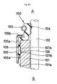
- This valve stem seal 100 is mounted and fixed in the fitted condition to the end part of an outer peripheral surface 101a of a valve stem guide 101, is comprising: a seal lip 104 comprising a garter spring 103 extending toward a sealing fluid side-A for sealing a valve stem 102 to apply a tension to the outer peripheral side; an approximately L-letter shaped metal attachment ring 105 having a seal lip 104 arranged at a flange part 105b extending to the inner diameter direction from the end part of the sealing fluid side-A of the cylindrical part 105a extending axially; and an inner peripheral fitting part 106 of the rubber elastic body integrally molded with the seal lip 104 at the opposite of a sealing fluid side-B from the seal lip 104 .
- the inner peripheral fitting part 106 is arranged at the inner peripheral side of the cylindrical part 105a of the attachment ring 105, and a plurality of fitting projections (107A,107B) are formed axially side-by-side on the inner peripheral surface 106a thereof.
- the fitting projections 107A of the sealing fluid side positioned at the sealing fluid side-A among these fitting projections 107 is drawn and pressed onto the outer peripheral surface 101 a by the inner peripheral fitting part 106 fitting into the valve stem guide 101 to ensure the sealing performance, and the fitting projections 107B of the opposite of the sealing fluid side is fitted with a concave part 108 formed on an outer peripheral surface 101a of the valve stem guide 101 to prevent disengaging of the valve stem seal 100 from the valve stem guide 101.
- the fitting projections 107 is designed to allow easy mounting with hand assembling or the like using a low fitting force by employing a projection shape to make the contact area smaller, therefore, when mounting the valve stem guide 101 to the valve stem seal 100 with hand assembly work, the fitting force is small, and moreover, the outer peripheral side of the inner peripheral fitting part 106 having the fitting projections 107 formed thereon is covered by the metal attachment ring 105, therefore it is difficult to confirm by hand feel that the fitting projections 107B of the opposite of the sealing fluid side is fitted with the concave part 108 formed on the valve stem guide 101, hence, work to reconfirm the fitted condition is required, causing a problem of reduced work efficiency. Incidentally, significantly increasing the fitting force could not be an effective solution as it will hinder hand assembly work.
- the present invention is made to solve the aforegoing problems, and the purpose is to provide a valve stem seal capable of offering a small fitting force so as to allow the valve stem seal to be mounted to the valve stem guide by hand assembling, as well as allowing a hand to sense and confirm that the fitting projections formed on the inner peripheral surface of the inner peripheral fitting part is fitted into the concave part of the outer peripheral surface of the valve stem guide.
- a valve stem seal comprises the features of claim 1 of this invention.
- a valve stem seal is comprising a seal lip for sealing the valve stem, a metal attachment ring having said seal lip arranged at the end part of the sealing fluid side thereof and an inner peripheral fitting part of a rubber elastic body having a plurality of the fitting projections formed axially side-by-side on the inner peripheral surface thereof, wherein the fitting projections of the opposite of the sealing fluid side among said fitting projections are fitted and mounted to a concave part formed on the outer peripheral surface of a valve stem guide, and wherein said inner peripheral fitting part is formed with: the inner peripheral fitting part of the sealing fluid side arranged at the inner peripheral side of said attachment ring, and having the fitting projections other than said fitting projections of the opposite of the sealing fluid side formed on the inner peripheral surface thereof; and with the inner peripheral fitting part of the opposite of the sealing fluid side thicker than the inner peripheral fitting part of the sealing fluid side, formed so as to protrude from the end part of the opposite of the sealing fluid side of said attachment ring, and having said fitting projections of the opposite of the sealing fluid side formed on the
- the present invention produces the following effect. More specifically, in a valve stem seal according to claim 1 of this invention comprising the above described constitutions, the inner peripheral fitting part of the opposite of the sealing fluid side is formed so as to protrude from the end part of the opposite of the sealing fluid side and the outer peripheral surface thereof is not covered with the attachment ring, thereby the thickness thereof can be made thicker than that of the inner peripheral fitting part of the sealing fluid side to increase the rigidity, and thereby the load difference (load reduction amount) can be made greater at the time when the fitting projections of the opposite of the sealing fluid side formed on the inner peripheral surface thereof is fitted into the concave part formed on the outer peripheral surface of the valve stem guide, allowing the mounting feel ("JUST" feel) of the fitted condition to be felt by hand, eliminating the confirmation work and increasing work efficiency.
- the load difference load reduction amount
- the outer peripheral surface thereof is not covered with the metal attachment ring and thus may be bent to the outer peripheral side, thereby fitting force becomes greater at the time of assembling allowing hand assembling to be performed without difficulty.
- the fitting projections other than the fitting projections of the opposite of the sealing fluid side formed on the inner peripheral surface of the inner peripheral fitting part of the sealing fluid side is drawn and pressed onto the outer peripheral surface of the valve stem guide by the fitting force of the inner peripheral fitting part of the sealing fluid side, since the outer peripheral side of the inner peripheral fitting part of the sealing fluid side is covered with the metal attachment ring, the fitting force thereof can also act to ensure the sealing effect with the valve stem guide as with the traditional means.
- Fig. 1 is a cross-sectional view showing a valve stem seal to which the present invention was applied in the mounted condition
- Fig. 2 is a cross-section of the valve stem seal unit in Fig. 1.
- a valve stem seal 1 is for sealing the peripheral surface of a valve stem 10 used where a valve for intake and exhaust of an internal combustion engine is arranged at the opposite of the sealing fluid side, is mounted by fitting into the end part of the sealing fluid side-A at the outer peripheral side of a valve stem guide 20, and is comprising a seal lip 30, an attachment ring 40 and an inner peripheral fitting part 50.
- the seal lip 30 is molded of the rubber elastic body and arranged at the end part of the sealing fluid side-A of the attachment ring 40 discussed below, a lip base 31 is adhered to the attachment ring 40, a lip tip part 32 extending from the lip base 31 thereof toward the sealing fluid side-A is provided so as to be slidably and closely in contact with the valve stem 10, and a garter spring 33 for radially applying a tension is mounted at the outer peripheral side of the lip tip part 32 .
- the attachment ring 40 is molded of metal, is comprising a cylindrical portion 41, an inner diameter flange part 42 extending from the end part of the sealing fluid side-A of the cylindrical portion 41 thereof to the inner diameter direction; and an outer diameter flange part 43 extending from the end part of the opposite of the sealing fluid side-B of the cylindrical portion 41 to the outer diameter direction, and the lip base 31 is adhered to the inner diameter flange part 42 so as to cover thereof, and the cylindrical portion 41 is provided so as to be fitted into an outer peripheral surface 21 of the valve stem guide 20.
- the inner peripheral fitting part 50 is integrally molded with the seal lip 30 by the rubber elastic body, is arranged at the inner peripheral side of the cylindrical portion 41 of the attachment ring 40, and is formed with an inner peripheral fitting part 51 of the sealing fluid side having a fitting projections 60A of the sealing fluid side formed on an inner peripheral surface 51 a, and with an inner peripheral fitting part 52 of the opposite of a sealing fluid side provided so as to protrude from the sealing fluid side-B opposite from the outer diameter flange part 43 of the attachment ring 40, and integrally molded with the inner peripheral fitting part 51 of the sealing fluid side.
- an fitting projections 60B of the opposite of the sealing fluid side fitted with a concave part 22 formed on the outer peripheral surface 21 of the valve stem guide 20 is formed on an inner peripheral surface 52a thereof, and an outer peripheral surface 52b is not covered with the attachment ring 40, and therefore is thicker in the outer diameter direction than the inner peripheral fitting part 51 of the sealing fluid side.
- the valve stem seal 1 constituted as described above is mounted by inserting from the sealing fluid side-A and fitting the inner peripheral fitting part 50 thereof into the outer peripheral surface 21 of the valve stem guide 20.
- the outer peripheral surface 52b of the inner peripheral fitting part 52 of the opposite of the sealing fluid side on which the fitting projections 60B of the opposite of the sealing fluid side is formed us not covered with the attachment ring 40, thereby the thickness can be increased in the outer diameter direction from the inner peripheral fitting part 51 of the sealing fluid side to increase the rigidity, and the load difference (load reduction amount) at the time when the fitting projections 60B of the opposite of the sealing fluid side is fitted into the concave part 22 formed on the outer peripheral surface 21 of the valve stem guide 20 can be increased.
- the mounting feel (JUST" feel) at the time of fitting the fitting projections 60B of the opposite of the sealing fluid side into the concave part 22 can be felt and confirmed by hand, and thereby the reconfirmation work is eliminated and the work efficiency can be improved.
- the outer peripheral surface 52b is not covered with the metal attachment ring 40 and thus the outer peripheral side can be bent to the outer peripheral side, and even when the fitting projections 60B of the opposite of the sealing fluid side formed on the inner peripheral surface 52a is made to fit into the concave part 22 formed on the valve stem guide 20, hand assembling can be performed.
- the inner peripheral fitting part 51 of the sealing fluid side having the fitting projections 60A of the sealing fluid side formed thereon is arranged at the inner peripheral side of the cylindrical portion 41 of the attachment ring 40, therefore the inner peripheral fitting part 51 of the sealing fluid side can be made to fit into the outer peripheral surface 21 of the valve stem guide 20, for the fitting projections 60A of the sealing fluid side formed on the inner peripheral surface 51a to be drawn and pressed onto, the fitting force of the attachment ring 40 can also act to ensure the sealing effect as before.
Landscapes
- Engineering & Computer Science (AREA)
- General Engineering & Computer Science (AREA)
- Mechanical Engineering (AREA)
- Sealing With Elastic Sealing Lips (AREA)
- Lift Valve (AREA)
- Temperature-Responsive Valves (AREA)
Abstract
Description
- The present invention relates to a valve stem seal for sealing a valve stem used where a valve for intake and exhaust of an internal combustion engine is arranged.
- Traditionally, seals such as shown in Fig. 3 and Fig. 4 have been known as a valve stem seals comprising an inner peripheral fitting part having a plurality of fitting projections formed axially side-by-side on the inner peripheral surface thereof, arranged at the inner peripheral side of an attachment ring (See
unexamined Patent Publication JP 11-351402 A unexamined Patent Publication JP 2003-343733 A - This
valve stem seal 100 is mounted and fixed in the fitted condition to the end part of an outerperipheral surface 101a of avalve stem guide 101, is comprising: aseal lip 104 comprising agarter spring 103 extending toward a sealing fluid side-A for sealing avalve stem 102 to apply a tension to the outer peripheral side; an approximately L-letter shapedmetal attachment ring 105 having aseal lip 104 arranged at aflange part 105b extending to the inner diameter direction from the end part of the sealing fluid side-A of thecylindrical part 105a extending axially; and an innerperipheral fitting part 106 of the rubber elastic body integrally molded with theseal lip 104 at the opposite of a sealing fluid side-B from theseal lip 104 . Furthermore, the innerperipheral fitting part 106 is arranged at the inner peripheral side of thecylindrical part 105a of theattachment ring 105, and a plurality of fitting projections (107A,107B) are formed axially side-by-side on the innerperipheral surface 106a thereof. Thefitting projections 107A of the sealing fluid side positioned at the sealing fluid side-A among these fitting projections 107 is drawn and pressed onto the outerperipheral surface 101 a by the innerperipheral fitting part 106 fitting into thevalve stem guide 101 to ensure the sealing performance, and thefitting projections 107B of the opposite of the sealing fluid side is fitted with aconcave part 108 formed on an outerperipheral surface 101a of thevalve stem guide 101 to prevent disengaging of thevalve stem seal 100 from thevalve stem guide 101. - However, the fitting projections 107 is designed to allow easy mounting with hand assembling or the like using a low fitting force by employing a projection shape to make the contact area smaller, therefore, when mounting the
valve stem guide 101 to thevalve stem seal 100 with hand assembly work, the fitting force is small, and moreover, the outer peripheral side of the innerperipheral fitting part 106 having the fitting projections 107 formed thereon is covered by themetal attachment ring 105, therefore it is difficult to confirm by hand feel that thefitting projections 107B of the opposite of the sealing fluid side is fitted with theconcave part 108 formed on thevalve stem guide 101, hence, work to reconfirm the fitted condition is required, causing a problem of reduced work efficiency. Incidentally, significantly increasing the fitting force could not be an effective solution as it will hinder hand assembly work. - The present invention is made to solve the aforegoing problems, and the purpose is to provide a valve stem seal capable of offering a small fitting force so as to allow the valve stem seal to be mounted to the valve stem guide by hand assembling, as well as allowing a hand to sense and confirm that the fitting projections formed on the inner peripheral surface of the inner peripheral fitting part is fitted into the concave part of the outer peripheral surface of the valve stem guide.
- To achieve the above described purpose, a valve stem seal comprises the features of
claim 1 of this invention. - A valve stem seal is comprising a seal lip for sealing the valve stem, a metal attachment ring having said seal lip arranged at the end part of the sealing fluid side thereof and an inner peripheral fitting part of a rubber elastic body having a plurality of the fitting projections formed axially side-by-side on the inner peripheral surface thereof, wherein the fitting projections of the opposite of the sealing fluid side among said fitting projections are fitted and mounted to a concave part formed on the outer peripheral surface of a valve stem guide, and wherein said inner peripheral fitting part is formed with: the inner peripheral fitting part of the sealing fluid side arranged at the inner peripheral side of said attachment ring, and having the fitting projections other than said fitting projections of the opposite of the sealing fluid side formed on the inner peripheral surface thereof; and with the inner peripheral fitting part of the opposite of the sealing fluid side thicker than the inner peripheral fitting part of the sealing fluid side, formed so as to protrude from the end part of the opposite of the sealing fluid side of said attachment ring, and having said fitting projections of the opposite of the sealing fluid side formed on the inner peripheral surface thereof.
- The present invention produces the following effect. More specifically, in a valve stem seal according to
claim 1 of this invention comprising the above described constitutions, the inner peripheral fitting part of the opposite of the sealing fluid side is formed so as to protrude from the end part of the opposite of the sealing fluid side and the outer peripheral surface thereof is not covered with the attachment ring, thereby the thickness thereof can be made thicker than that of the inner peripheral fitting part of the sealing fluid side to increase the rigidity, and thereby the load difference (load reduction amount) can be made greater at the time when the fitting projections of the opposite of the sealing fluid side formed on the inner peripheral surface thereof is fitted into the concave part formed on the outer peripheral surface of the valve stem guide, allowing the mounting feel ("JUST" feel) of the fitted condition to be felt by hand, eliminating the confirmation work and increasing work efficiency. - In addition, even when the thickness of the inner peripheral fitting part of the opposite of the sealing fluid side is increased to increase the rigidity, the outer peripheral surface thereof is not covered with the metal attachment ring and thus may be bent to the outer peripheral side, thereby fitting force becomes greater at the time of assembling allowing hand assembling to be performed without difficulty.
- Moreover, when the fitting projections other than the fitting projections of the opposite of the sealing fluid side formed on the inner peripheral surface of the inner peripheral fitting part of the sealing fluid side is drawn and pressed onto the outer peripheral surface of the valve stem guide by the fitting force of the inner peripheral fitting part of the sealing fluid side, since the outer peripheral side of the inner peripheral fitting part of the sealing fluid side is covered with the metal attachment ring, the fitting force thereof can also act to ensure the sealing effect with the valve stem guide as with the traditional means.
-
- Fig. 1 A cross-sectional view showing a valve stem seal according to the present invention in the mounted condition
- Fig. 2 A cross-section of a valve stem seal unit in Fig. 1
- Fig. 3 A cross-sectional view showing a valve stem seal according to a conventional example
- Fig. 4 A cross-section of a valve stem seal unit in Fig. 3
- Hereinafter, this invention will be described by exemplifying a preferred embodiment with the reference to the drawings.
- Fig. 1 is a cross-sectional view showing a valve stem seal to which the present invention was applied in the mounted condition, and Fig. 2 is a cross-section of the valve stem seal unit in Fig. 1.
- A
valve stem seal 1 according to the present invention is for sealing the peripheral surface of avalve stem 10 used where a valve for intake and exhaust of an internal combustion engine is arranged at the opposite of the sealing fluid side, is mounted by fitting into the end part of the sealing fluid side-A at the outer peripheral side of a valve stem guide 20, and is comprising aseal lip 30, anattachment ring 40 and an innerperipheral fitting part 50. - The
seal lip 30 is molded of the rubber elastic body and arranged at the end part of the sealing fluid side-A of theattachment ring 40 discussed below, alip base 31 is adhered to theattachment ring 40, alip tip part 32 extending from thelip base 31 thereof toward the sealing fluid side-A is provided so as to be slidably and closely in contact with thevalve stem 10, and agarter spring 33 for radially applying a tension is mounted at the outer peripheral side of thelip tip part 32 . - The
attachment ring 40 is molded of metal, is comprising acylindrical portion 41, an innerdiameter flange part 42 extending from the end part of the sealing fluid side-A of thecylindrical portion 41 thereof to the inner diameter direction; and an outerdiameter flange part 43 extending from the end part of the opposite of the sealing fluid side-B of thecylindrical portion 41 to the outer diameter direction, and thelip base 31 is adhered to the innerdiameter flange part 42 so as to cover thereof, and thecylindrical portion 41 is provided so as to be fitted into an outerperipheral surface 21 of the valve stem guide 20. - The inner
peripheral fitting part 50 is integrally molded with theseal lip 30 by the rubber elastic body, is arranged at the inner peripheral side of thecylindrical portion 41 of theattachment ring 40, and is formed with an innerperipheral fitting part 51 of the sealing fluid side having afitting projections 60A of the sealing fluid side formed on an innerperipheral surface 51 a, and with an innerperipheral fitting part 52 of the opposite of a sealing fluid side provided so as to protrude from the sealing fluid side-B opposite from the outerdiameter flange part 43 of theattachment ring 40, and integrally molded with the innerperipheral fitting part 51 of the sealing fluid side. - In the inner
peripheral fitting part 52 of the opposite side of the sealing fluid side, anfitting projections 60B of the opposite of the sealing fluid side fitted with aconcave part 22 formed on the outerperipheral surface 21 of the valve stem guide 20 is formed on an innerperipheral surface 52a thereof, and an outerperipheral surface 52b is not covered with theattachment ring 40, and therefore is thicker in the outer diameter direction than the innerperipheral fitting part 51 of the sealing fluid side. - The
valve stem seal 1 constituted as described above is mounted by inserting from the sealing fluid side-A and fitting the innerperipheral fitting part 50 thereof into the outerperipheral surface 21 of the valve stem guide 20. In this case, the outerperipheral surface 52b of the inner peripheral fittingpart 52 of the opposite of the sealing fluid side on which thefitting projections 60B of the opposite of the sealing fluid side is formed, us not covered with theattachment ring 40, thereby the thickness can be increased in the outer diameter direction from the innerperipheral fitting part 51 of the sealing fluid side to increase the rigidity, and the load difference (load reduction amount) at the time when thefitting projections 60B of the opposite of the sealing fluid side is fitted into theconcave part 22 formed on the outerperipheral surface 21 of the valve stem guide 20 can be increased. Accordingly, when hand assembling, the mounting feel ("JUST" feel) at the time of fitting thefitting projections 60B of the opposite of the sealing fluid side into theconcave part 22 can be felt and confirmed by hand, and thereby the reconfirmation work is eliminated and the work efficiency can be improved. - Moreover, even when the thickness of the inner
peripheral fitting part 52 of the opposite of the sealing fluid side is increased to enhance the rigidity, the outerperipheral surface 52b is not covered with themetal attachment ring 40 and thus the outer peripheral side can be bent to the outer peripheral side, and even when thefitting projections 60B of the opposite of the sealing fluid side formed on the innerperipheral surface 52a is made to fit into theconcave part 22 formed on the valve stem guide 20, hand assembling can be performed. - Furthermore, the inner
peripheral fitting part 51 of the sealing fluid side having thefitting projections 60A of the sealing fluid side formed thereon is arranged at the inner peripheral side of thecylindrical portion 41 of theattachment ring 40, therefore the innerperipheral fitting part 51 of the sealing fluid side can be made to fit into the outerperipheral surface 21 of the valve stem guide 20, for thefitting projections 60A of the sealing fluid side formed on the innerperipheral surface 51a to be drawn and pressed onto, the fitting force of theattachment ring 40 can also act to ensure the sealing effect as before.
Claims (5)
- A valve stem seal (1) comprising a seal lip (30) for sealing a valve stem (10), an attachment ring (40) having said seal lip (30) arranged at the end part of a sealing fluid side (A) thereof and an inner peripheral fitting part (50) of a rubber elastic body having a plurality of the fitting projections (60A, 60B) formed axially side-by-side on the inner peripheral surface thereof, characterized in that the fitting projections (60B) of the opposite of the sealing fluid side (B) among said fitting projections (60A, 60B) are other than said fitting projections (60A) of the sealing fluid side (A).
- A valve stem seal (1) according to claim 1, wherein an inner peripheral fitting part (52) of the opposite of the sealing fluid side (B) is thicker than an inner peripheral fitting part (51) of the sealing fluid side (A), formed so as to protrude from the end part of the opposite of the sealing fluid side (B) of said attachment ring (40), and having said fitting projections (60B) of the opposite of the sealing fluid side (B) formed on the inner peripheral surface thereof.
- A valve stem seal (1) according to claim 1 or 2, wherein said inner peripheral fitting part (50) is formed with: an inner peripheral fitting part (51) of the sealing fluid side (A) arranged at the inner peripheral side of said attachment ring (40), and having the fitting projections (60A) other than said fitting projections (60B) of the opposite of the sealing fluid side (B) formed on the inner peripheral surface thereof.
- A valve stem seal (1) according to one of the claims 1 to 3, wherein the attachment ring (40) is comprising a cylindrical portion (41), an inner diameter flange part (42) extending from the end part of the sealing fluid side (A) of the cylindrical portion (41) thereof to the inner diameter direction, and an outer diameter flange part (43) extending from the end part of the opposite of the sealing fluid side (B) of the cylindrical portion (41) to the outer diameter direction.
- An arrangement comprising a valve stem seal (1) according to one of the claims 1 to 4, comprising a seal lip (30) for sealing the valve stem (10), a metal attachment ring (40) having said seal lip (30) arranged at the end part of the sealing fluid side (A) thereof and an inner peripheral fitting part (50) of a rubber elastic body having a plurality of the fitting projections (60A, 60B) formed axially side-by-side on the inner peripheral surface thereof, wherein the fitting projections (60B) of the opposite of the sealing fluid side (B) among said fitting projections (60A, 60B) are fitted and mounted to a concave part (22) formed on the outer peripheral surface of a valve stem guide (20), and wherein said inner peripheral fitting part (50) is formed with: the inner peripheral fitting part (51) of the sealing fluid side (A) arranged at the inner peripheral side of said attachment ring (40), and having the fitting projections (60A) other than said fitting projections (60B) of the opposite of the sealing fluid side (B) formed on the inner peripheral surface thereof; and with the inner peripheral fitting part (52) of the opposite of the sealing fluid side (B) thicker than the inner peripheral fitting part (51) of the sealing fluid side (A), formed so as to protrude from the end part of the opposite of the sealing fluid side (B) of said attachment ring (40), and having said fitting projections (60B) of the opposite of the sealing fluid side (B) formed on the inner peripheral surface thereof.
Applications Claiming Priority (1)
| Application Number | Priority Date | Filing Date | Title |
|---|---|---|---|
| JP2006140069A JP4788906B2 (en) | 2006-05-19 | 2006-05-19 | Valve stem seal |
Publications (3)
| Publication Number | Publication Date |
|---|---|
| EP1857645A2 true EP1857645A2 (en) | 2007-11-21 |
| EP1857645A3 EP1857645A3 (en) | 2009-12-16 |
| EP1857645B1 EP1857645B1 (en) | 2010-09-08 |
Family
ID=38255025
Family Applications (1)
| Application Number | Title | Priority Date | Filing Date |
|---|---|---|---|
| EP07009573A Not-in-force EP1857645B1 (en) | 2006-05-19 | 2007-05-12 | Valve stem seal |
Country Status (4)
| Country | Link |
|---|---|
| EP (1) | EP1857645B1 (en) |
| JP (1) | JP4788906B2 (en) |
| AT (1) | ATE480696T1 (en) |
| DE (1) | DE602007008974D1 (en) |
Cited By (1)
| Publication number | Priority date | Publication date | Assignee | Title |
|---|---|---|---|---|
| AU2022201961B2 (en) * | 2021-04-01 | 2024-03-21 | Kabushiki Kaisha Toyota Jidoshokki | Valve Stem Seal Structure |
Families Citing this family (1)
| Publication number | Priority date | Publication date | Assignee | Title |
|---|---|---|---|---|
| JP2009264415A (en) * | 2008-04-22 | 2009-11-12 | Nok Corp | Valve stem seal mounting structure |
Citations (2)
| Publication number | Priority date | Publication date | Assignee | Title |
|---|---|---|---|---|
| JPH11351402A (en) | 1998-06-09 | 1999-12-24 | Nok Corp | Valve stem seal |
| JP2003343733A (en) | 2002-05-24 | 2003-12-03 | Nok Corp | Sealing device |
Family Cites Families (10)
| Publication number | Priority date | Publication date | Assignee | Title |
|---|---|---|---|---|
| JPS499937U (en) * | 1972-05-01 | 1974-01-28 | ||
| IT7967950A0 (en) * | 1979-05-07 | 1979-05-07 | Supertex Spa | ASSEMBLY CONSISTING OF A SEAL FOR VALVE STEMS AND A SPRING SUPPORT CAP |
| JPS6117105U (en) * | 1984-07-03 | 1986-01-31 | 株式会社 荒井製作所 | valve stem seal |
| JPH023001U (en) * | 1988-06-20 | 1990-01-10 | ||
| IT227530Y1 (en) * | 1992-04-14 | 1997-12-15 | Rft Spa | SEAL GASKET FOR A SLIDING STEM AGAINST THE ACTION OF ELASTIC DEVICES, IN PARTICULAR FOR A VALVE STEM OF A COMBU ENGINE |
| JP3155483B2 (en) * | 1997-01-23 | 2001-04-09 | 株式会社荒井製作所 | Valve stem seal |
| DE19949248A1 (en) * | 1999-10-13 | 2001-04-19 | Freudenberg Carl Fa | Valve stem seal |
| JP4310596B2 (en) * | 2000-03-14 | 2009-08-12 | Nok株式会社 | Oil seal |
| JP2004068888A (en) * | 2002-08-05 | 2004-03-04 | Nok Corp | Valve stem seal |
| JP2007298143A (en) * | 2006-05-02 | 2007-11-15 | Nok Corp | Oil seal |
-
2006
- 2006-05-19 JP JP2006140069A patent/JP4788906B2/en not_active Expired - Fee Related
-
2007
- 2007-05-12 EP EP07009573A patent/EP1857645B1/en not_active Not-in-force
- 2007-05-12 AT AT07009573T patent/ATE480696T1/en not_active IP Right Cessation
- 2007-05-12 DE DE602007008974T patent/DE602007008974D1/en active Active
Patent Citations (2)
| Publication number | Priority date | Publication date | Assignee | Title |
|---|---|---|---|---|
| JPH11351402A (en) | 1998-06-09 | 1999-12-24 | Nok Corp | Valve stem seal |
| JP2003343733A (en) | 2002-05-24 | 2003-12-03 | Nok Corp | Sealing device |
Cited By (1)
| Publication number | Priority date | Publication date | Assignee | Title |
|---|---|---|---|---|
| AU2022201961B2 (en) * | 2021-04-01 | 2024-03-21 | Kabushiki Kaisha Toyota Jidoshokki | Valve Stem Seal Structure |
Also Published As
| Publication number | Publication date |
|---|---|
| ATE480696T1 (en) | 2010-09-15 |
| JP2007309442A (en) | 2007-11-29 |
| DE602007008974D1 (en) | 2010-10-21 |
| JP4788906B2 (en) | 2011-10-05 |
| EP1857645A3 (en) | 2009-12-16 |
| EP1857645B1 (en) | 2010-09-08 |
Similar Documents
| Publication | Publication Date | Title |
|---|---|---|
| EP1854965B1 (en) | Oil seal | |
| EP1837562A1 (en) | Sealing device with sound insulating seal | |
| US6764079B1 (en) | Valve seal assembly with straight-walled retainer | |
| EP1226753A3 (en) | Sealing structure for fishing reel | |
| US10767519B2 (en) | Valve stem seal and hermetic sealing structure | |
| EP1857645B1 (en) | Valve stem seal | |
| US7753611B2 (en) | Ball-and-socket joint | |
| EP2236776B1 (en) | Valve stem seal | |
| EP1890058A1 (en) | Oil seal for valve stem | |
| JP2003254020A (en) | Valve stem seal for internal combustion engine | |
| WO2006038347A1 (en) | Sealing device | |
| JP4581309B2 (en) | Valve stem seal | |
| JP2005308204A (en) | Oil seal | |
| JP3373418B2 (en) | Mounting structure of in-cylinder fuel injection valve | |
| JP2019044898A (en) | Valve stem seal | |
| JP2011032891A (en) | Seal structure of resin cover member for engine | |
| JP4427977B2 (en) | Sealing device | |
| JP5063393B2 (en) | Oil level gauge guide tube mounting structure | |
| JP2007024205A (en) | Oil seal | |
| JP3960139B2 (en) | Valve stem seal | |
| JPH0749138Y2 (en) | Sealing device | |
| JP2008309273A (en) | Sealing device | |
| JPH0559056U (en) | Oil seal | |
| CN112013115B (en) | Sealing device | |
| JPH0835563A (en) | Sealing device for reciprocating movement |
Legal Events
| Date | Code | Title | Description |
|---|---|---|---|
| PUAI | Public reference made under article 153(3) epc to a published international application that has entered the european phase |
Free format text: ORIGINAL CODE: 0009012 |
|
| AK | Designated contracting states |
Kind code of ref document: A2 Designated state(s): AT BE BG CH CY CZ DE DK EE ES FI FR GB GR HU IE IS IT LI LT LU LV MC MT NL PL PT RO SE SI SK TR |
|
| AX | Request for extension of the european patent |
Extension state: AL BA HR MK YU |
|
| 17P | Request for examination filed |
Effective date: 20080411 |
|
| PUAL | Search report despatched |
Free format text: ORIGINAL CODE: 0009013 |
|
| AK | Designated contracting states |
Kind code of ref document: A3 Designated state(s): AT BE BG CH CY CZ DE DK EE ES FI FR GB GR HU IE IS IT LI LT LU LV MC MT NL PL PT RO SE SI SK TR |
|
| AX | Request for extension of the european patent |
Extension state: AL BA HR MK RS |
|
| GRAP | Despatch of communication of intention to grant a patent |
Free format text: ORIGINAL CODE: EPIDOSNIGR1 |
|
| GRAS | Grant fee paid |
Free format text: ORIGINAL CODE: EPIDOSNIGR3 |
|
| GRAA | (expected) grant |
Free format text: ORIGINAL CODE: 0009210 |
|
| AKX | Designation fees paid |
Designated state(s): AT BE BG CH CY CZ DE DK EE ES FI FR GB GR HU IE IS IT LI LT LU LV MC MT NL PL PT RO SE SI SK TR |
|
| AK | Designated contracting states |
Kind code of ref document: B1 Designated state(s): AT BE BG CH CY CZ DE DK EE ES FI FR GB GR HU IE IS IT LI LT LU LV MC MT NL PL PT RO SE SI SK TR |
|
| REG | Reference to a national code |
Ref country code: GB Ref legal event code: FG4D |
|
| REG | Reference to a national code |
Ref country code: CH Ref legal event code: EP |
|
| REG | Reference to a national code |
Ref country code: IE Ref legal event code: FG4D |
|
| REF | Corresponds to: |
Ref document number: 602007008974 Country of ref document: DE Date of ref document: 20101021 Kind code of ref document: P |
|
| REG | Reference to a national code |
Ref country code: NL Ref legal event code: VDEP Effective date: 20100908 |
|
| PG25 | Lapsed in a contracting state [announced via postgrant information from national office to epo] |
Ref country code: FI Free format text: LAPSE BECAUSE OF FAILURE TO SUBMIT A TRANSLATION OF THE DESCRIPTION OR TO PAY THE FEE WITHIN THE PRESCRIBED TIME-LIMIT Effective date: 20100908 Ref country code: AT Free format text: LAPSE BECAUSE OF FAILURE TO SUBMIT A TRANSLATION OF THE DESCRIPTION OR TO PAY THE FEE WITHIN THE PRESCRIBED TIME-LIMIT Effective date: 20100908 Ref country code: LT Free format text: LAPSE BECAUSE OF FAILURE TO SUBMIT A TRANSLATION OF THE DESCRIPTION OR TO PAY THE FEE WITHIN THE PRESCRIBED TIME-LIMIT Effective date: 20100908 |
|
| LTIE | Lt: invalidation of european patent or patent extension |
Effective date: 20100908 |
|
| PG25 | Lapsed in a contracting state [announced via postgrant information from national office to epo] |
Ref country code: SI Free format text: LAPSE BECAUSE OF FAILURE TO SUBMIT A TRANSLATION OF THE DESCRIPTION OR TO PAY THE FEE WITHIN THE PRESCRIBED TIME-LIMIT Effective date: 20100908 Ref country code: PL Free format text: LAPSE BECAUSE OF FAILURE TO SUBMIT A TRANSLATION OF THE DESCRIPTION OR TO PAY THE FEE WITHIN THE PRESCRIBED TIME-LIMIT Effective date: 20100908 Ref country code: CY Free format text: LAPSE BECAUSE OF FAILURE TO SUBMIT A TRANSLATION OF THE DESCRIPTION OR TO PAY THE FEE WITHIN THE PRESCRIBED TIME-LIMIT Effective date: 20100908 |
|
| PG25 | Lapsed in a contracting state [announced via postgrant information from national office to epo] |
Ref country code: GR Free format text: LAPSE BECAUSE OF FAILURE TO SUBMIT A TRANSLATION OF THE DESCRIPTION OR TO PAY THE FEE WITHIN THE PRESCRIBED TIME-LIMIT Effective date: 20101209 Ref country code: LV Free format text: LAPSE BECAUSE OF FAILURE TO SUBMIT A TRANSLATION OF THE DESCRIPTION OR TO PAY THE FEE WITHIN THE PRESCRIBED TIME-LIMIT Effective date: 20100908 Ref country code: SE Free format text: LAPSE BECAUSE OF FAILURE TO SUBMIT A TRANSLATION OF THE DESCRIPTION OR TO PAY THE FEE WITHIN THE PRESCRIBED TIME-LIMIT Effective date: 20100908 Ref country code: NL Free format text: LAPSE BECAUSE OF FAILURE TO SUBMIT A TRANSLATION OF THE DESCRIPTION OR TO PAY THE FEE WITHIN THE PRESCRIBED TIME-LIMIT Effective date: 20100908 |
|
| PG25 | Lapsed in a contracting state [announced via postgrant information from national office to epo] |
Ref country code: PT Free format text: LAPSE BECAUSE OF FAILURE TO SUBMIT A TRANSLATION OF THE DESCRIPTION OR TO PAY THE FEE WITHIN THE PRESCRIBED TIME-LIMIT Effective date: 20110110 Ref country code: RO Free format text: LAPSE BECAUSE OF FAILURE TO SUBMIT A TRANSLATION OF THE DESCRIPTION OR TO PAY THE FEE WITHIN THE PRESCRIBED TIME-LIMIT Effective date: 20100908 Ref country code: SK Free format text: LAPSE BECAUSE OF FAILURE TO SUBMIT A TRANSLATION OF THE DESCRIPTION OR TO PAY THE FEE WITHIN THE PRESCRIBED TIME-LIMIT Effective date: 20100908 Ref country code: EE Free format text: LAPSE BECAUSE OF FAILURE TO SUBMIT A TRANSLATION OF THE DESCRIPTION OR TO PAY THE FEE WITHIN THE PRESCRIBED TIME-LIMIT Effective date: 20100908 Ref country code: IS Free format text: LAPSE BECAUSE OF FAILURE TO SUBMIT A TRANSLATION OF THE DESCRIPTION OR TO PAY THE FEE WITHIN THE PRESCRIBED TIME-LIMIT Effective date: 20110108 Ref country code: CZ Free format text: LAPSE BECAUSE OF FAILURE TO SUBMIT A TRANSLATION OF THE DESCRIPTION OR TO PAY THE FEE WITHIN THE PRESCRIBED TIME-LIMIT Effective date: 20100908 |
|
| PG25 | Lapsed in a contracting state [announced via postgrant information from national office to epo] |
Ref country code: BE Free format text: LAPSE BECAUSE OF FAILURE TO SUBMIT A TRANSLATION OF THE DESCRIPTION OR TO PAY THE FEE WITHIN THE PRESCRIBED TIME-LIMIT Effective date: 20100908 Ref country code: ES Free format text: LAPSE BECAUSE OF FAILURE TO SUBMIT A TRANSLATION OF THE DESCRIPTION OR TO PAY THE FEE WITHIN THE PRESCRIBED TIME-LIMIT Effective date: 20101219 |
|
| PLBE | No opposition filed within time limit |
Free format text: ORIGINAL CODE: 0009261 |
|
| STAA | Information on the status of an ep patent application or granted ep patent |
Free format text: STATUS: NO OPPOSITION FILED WITHIN TIME LIMIT |
|
| 26N | No opposition filed |
Effective date: 20110609 |
|
| PG25 | Lapsed in a contracting state [announced via postgrant information from national office to epo] |
Ref country code: DK Free format text: LAPSE BECAUSE OF FAILURE TO SUBMIT A TRANSLATION OF THE DESCRIPTION OR TO PAY THE FEE WITHIN THE PRESCRIBED TIME-LIMIT Effective date: 20100908 |
|
| REG | Reference to a national code |
Ref country code: DE Ref legal event code: R097 Ref document number: 602007008974 Country of ref document: DE Effective date: 20110609 |
|
| PG25 | Lapsed in a contracting state [announced via postgrant information from national office to epo] |
Ref country code: MT Free format text: LAPSE BECAUSE OF FAILURE TO SUBMIT A TRANSLATION OF THE DESCRIPTION OR TO PAY THE FEE WITHIN THE PRESCRIBED TIME-LIMIT Effective date: 20100908 Ref country code: MC Free format text: LAPSE BECAUSE OF NON-PAYMENT OF DUE FEES Effective date: 20110531 |
|
| REG | Reference to a national code |
Ref country code: CH Ref legal event code: PL |
|
| PG25 | Lapsed in a contracting state [announced via postgrant information from national office to epo] |
Ref country code: LI Free format text: LAPSE BECAUSE OF NON-PAYMENT OF DUE FEES Effective date: 20110531 Ref country code: CH Free format text: LAPSE BECAUSE OF NON-PAYMENT OF DUE FEES Effective date: 20110531 |
|
| REG | Reference to a national code |
Ref country code: IE Ref legal event code: MM4A |
|
| PG25 | Lapsed in a contracting state [announced via postgrant information from national office to epo] |
Ref country code: IE Free format text: LAPSE BECAUSE OF NON-PAYMENT OF DUE FEES Effective date: 20110512 |
|
| PG25 | Lapsed in a contracting state [announced via postgrant information from national office to epo] |
Ref country code: LU Free format text: LAPSE BECAUSE OF NON-PAYMENT OF DUE FEES Effective date: 20110512 |
|
| PG25 | Lapsed in a contracting state [announced via postgrant information from national office to epo] |
Ref country code: BG Free format text: LAPSE BECAUSE OF FAILURE TO SUBMIT A TRANSLATION OF THE DESCRIPTION OR TO PAY THE FEE WITHIN THE PRESCRIBED TIME-LIMIT Effective date: 20101208 Ref country code: TR Free format text: LAPSE BECAUSE OF FAILURE TO SUBMIT A TRANSLATION OF THE DESCRIPTION OR TO PAY THE FEE WITHIN THE PRESCRIBED TIME-LIMIT Effective date: 20100908 |
|
| PG25 | Lapsed in a contracting state [announced via postgrant information from national office to epo] |
Ref country code: HU Free format text: LAPSE BECAUSE OF FAILURE TO SUBMIT A TRANSLATION OF THE DESCRIPTION OR TO PAY THE FEE WITHIN THE PRESCRIBED TIME-LIMIT Effective date: 20100908 |
|
| REG | Reference to a national code |
Ref country code: FR Ref legal event code: PLFP Year of fee payment: 10 |
|
| REG | Reference to a national code |
Ref country code: FR Ref legal event code: PLFP Year of fee payment: 11 |
|
| REG | Reference to a national code |
Ref country code: FR Ref legal event code: PLFP Year of fee payment: 12 |
|
| PGFP | Annual fee paid to national office [announced via postgrant information from national office to epo] |
Ref country code: IT Payment date: 20220531 Year of fee payment: 16 Ref country code: GB Payment date: 20220522 Year of fee payment: 16 Ref country code: FR Payment date: 20220520 Year of fee payment: 16 Ref country code: DE Payment date: 20220602 Year of fee payment: 16 |
|
| REG | Reference to a national code |
Ref country code: DE Ref legal event code: R119 Ref document number: 602007008974 Country of ref document: DE |
|
| GBPC | Gb: european patent ceased through non-payment of renewal fee |
Effective date: 20230512 |
|
| PG25 | Lapsed in a contracting state [announced via postgrant information from national office to epo] |
Ref country code: IT Free format text: LAPSE BECAUSE OF NON-PAYMENT OF DUE FEES Effective date: 20230512 Ref country code: DE Free format text: LAPSE BECAUSE OF NON-PAYMENT OF DUE FEES Effective date: 20231201 Ref country code: GB Free format text: LAPSE BECAUSE OF NON-PAYMENT OF DUE FEES Effective date: 20230512 |
|
| PG25 | Lapsed in a contracting state [announced via postgrant information from national office to epo] |
Ref country code: FR Free format text: LAPSE BECAUSE OF NON-PAYMENT OF DUE FEES Effective date: 20230531 |