EP1857382A1 - Article dispensing device and method - Google Patents
Article dispensing device and method Download PDFInfo
- Publication number
- EP1857382A1 EP1857382A1 EP06711514A EP06711514A EP1857382A1 EP 1857382 A1 EP1857382 A1 EP 1857382A1 EP 06711514 A EP06711514 A EP 06711514A EP 06711514 A EP06711514 A EP 06711514A EP 1857382 A1 EP1857382 A1 EP 1857382A1
- Authority
- EP
- European Patent Office
- Prior art keywords
- article
- container
- map
- drug
- dispensing
- Prior art date
- Legal status (The legal status is an assumption and is not a legal conclusion. Google has not performed a legal analysis and makes no representation as to the accuracy of the status listed.)
- Withdrawn
Links
Images









Classifications
-
- B—PERFORMING OPERATIONS; TRANSPORTING
- B65—CONVEYING; PACKING; STORING; HANDLING THIN OR FILAMENTARY MATERIAL
- B65G—TRANSPORT OR STORAGE DEVICES, e.g. CONVEYORS FOR LOADING OR TIPPING, SHOP CONVEYOR SYSTEMS OR PNEUMATIC TUBE CONVEYORS
- B65G1/00—Storing articles, individually or in orderly arrangement, in warehouses or magazines
- B65G1/02—Storage devices
- B65G1/04—Storage devices mechanical
- B65G1/137—Storage devices mechanical with arrangements or automatic control means for selecting which articles are to be removed
-
- G—PHYSICS
- G07—CHECKING-DEVICES
- G07F—COIN-FREED OR LIKE APPARATUS
- G07F17/00—Coin-freed apparatus for hiring articles; Coin-freed facilities or services
- G07F17/0092—Coin-freed apparatus for hiring articles; Coin-freed facilities or services for assembling and dispensing of pharmaceutical articles
-
- B—PERFORMING OPERATIONS; TRANSPORTING
- B65—CONVEYING; PACKING; STORING; HANDLING THIN OR FILAMENTARY MATERIAL
- B65B—MACHINES, APPARATUS OR DEVICES FOR, OR METHODS OF, PACKAGING ARTICLES OR MATERIALS; UNPACKING
- B65B5/00—Packaging individual articles in containers or receptacles, e.g. bags, sacks, boxes, cartons, cans, jars
- B65B5/10—Filling containers or receptacles progressively or in stages by introducing successive articles, or layers of articles
-
- G—PHYSICS
- G07—CHECKING-DEVICES
- G07F—COIN-FREED OR LIKE APPARATUS
- G07F11/00—Coin-freed apparatus for dispensing, or the like, discrete articles
- G07F11/02—Coin-freed apparatus for dispensing, or the like, discrete articles from non-movable magazines
- G07F11/04—Coin-freed apparatus for dispensing, or the like, discrete articles from non-movable magazines in which magazines the articles are stored one vertically above the other
- G07F11/16—Delivery means
-
- G—PHYSICS
- G07—CHECKING-DEVICES
- G07F—COIN-FREED OR LIKE APPARATUS
- G07F11/00—Coin-freed apparatus for dispensing, or the like, discrete articles
- G07F11/02—Coin-freed apparatus for dispensing, or the like, discrete articles from non-movable magazines
- G07F11/04—Coin-freed apparatus for dispensing, or the like, discrete articles from non-movable magazines in which magazines the articles are stored one vertically above the other
- G07F11/16—Delivery means
- G07F11/165—Delivery means using xyz-picker or multi-dimensional article picking arrangements
-
- G—PHYSICS
- G07—CHECKING-DEVICES
- G07F—COIN-FREED OR LIKE APPARATUS
- G07F11/00—Coin-freed apparatus for dispensing, or the like, discrete articles
- G07F11/02—Coin-freed apparatus for dispensing, or the like, discrete articles from non-movable magazines
- G07F11/38—Coin-freed apparatus for dispensing, or the like, discrete articles from non-movable magazines in which the magazines are horizontal
-
- G—PHYSICS
- G16—INFORMATION AND COMMUNICATION TECHNOLOGY [ICT] SPECIALLY ADAPTED FOR SPECIFIC APPLICATION FIELDS
- G16H—HEALTHCARE INFORMATICS, i.e. INFORMATION AND COMMUNICATION TECHNOLOGY [ICT] SPECIALLY ADAPTED FOR THE HANDLING OR PROCESSING OF MEDICAL OR HEALTHCARE DATA
- G16H20/00—ICT specially adapted for therapies or health-improving plans, e.g. for handling prescriptions, for steering therapy or for monitoring patient compliance
- G16H20/10—ICT specially adapted for therapies or health-improving plans, e.g. for handling prescriptions, for steering therapy or for monitoring patient compliance relating to drugs or medications, e.g. for ensuring correct administration to patients
- G16H20/13—ICT specially adapted for therapies or health-improving plans, e.g. for handling prescriptions, for steering therapy or for monitoring patient compliance relating to drugs or medications, e.g. for ensuring correct administration to patients delivered from dispensers
Definitions
- the present invention relates to an article dispensing device for dispensing mainly a drug to a predetermined position in a tray.
- Patent Document 1 JP 2002-120913 A
- the interior of the tray is simply divided into a plurality of sections beforehand, merely deciding the section where the commodity supplied is to be accommodated.
- the kind of commodity that can be accommodated is restricted.
- this system is liable to involve non-transpensing construction allowing accommodation of commodities in the tray at high density.
- the present invention provides an article dispensing device including: a dispensing means for holding an article and dispensing it into a container; a storage means for storing a container map prepared by dividing an internal space of the container into a plurality of container virtual regions, and an article map prepared by dividing the article into a plurality of article virtual regions that are in a predetermined correlation with the container virtual regions; and a control means which calls from the storage means the article map of the article to be dispensed by the dispensing means and the container map of the container for accommodating the article, which searches for a vacant region by searching each container virtual region of the container map in a predetermined order, which specifies a dispensing position for the article according to the article map, and which drive-controls the dispensing means based on the specified dispensing position for causing the article held to be accommodated in the container.
- the article map stored in the storage means is provided with at least a stick-out region sticking out beyond the actual article size by an amount corresponding to one article virtual region, it is possible to reliably avoid interference between the articles. This is preferable in the point that it is possible to realize a smooth dispensing operation.
- the internal space of the container is considered in a three-dimensional terms, making it possible to dispense articles stacked together in a plurality of stages.
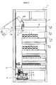
- Fig. 1 is a front view of a drug dispensing device according to this embodiment
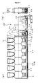
- Fig. 2 is a side view thereof.
- a plurality of shelf members 2 are arranged vertically side by side within a device main body 1, and drugs D accommodated in the shelf members 2 are conveyed downwards by a dispensing means provided on the front side of the device main body 1, that is, a drug conveying member 3, and are accommodated in a tray 5 conveyed along a tray conveying line 4.
- the front side of the device main body 1 is opened and closed by a door (not shown), and a plurality of guide members 6 are provided on the inner surfaces of the side walls thereof.
- the guide members 6 is composed of a first guide member 6a situated uppermost, and a second guide member 6b situated below the same.
- the guide wall 7 has a horizontally extending first guide surface 9 formed at the lower edge of the upper half thereof, and an arcuate second guide surface 10 formed at the forward end surface of the upper half thereof; on the front side of the lower half thereof, a support roller 11 is rotatably arranged.
- an intermediate rail portion 7a is slidably provided on a first rail portion 13 integrated with the guide wall 7, and a second rail portion 14 is slidably provided on the intermediate rail portion 7a, whereby the second rail portion 14 can reciprocate in the longitudinal direction of the device main body 1.
- a support wall 15 is formed above the second rail portion 14.
- a support shaft 16 rotatably supporting the shelf member 2.
- a spring 16a one end of which is fixed to the support wall 15, and the other end of which abuts an abutment/receiving portion 15a formed on the shelf member 2, whereby the shelf member 2 is urged in the horizontal direction.
- a locking/receiving portion 17 to which a lock portion 24 of a lock member 23 provided on the shelf member 2 is locked, whereby the shelf member 2 is prevented from rotating and is placed in a tilted state.
- the second guide member 6b is equipped with a support rail portion 18 supporting the shelf member 2 so as to allow it to slide in the longitudinal direction of the device main body 1.
- the shelf member 2 is just supported so as to be capable of reciprocating in the horizontal direction.
- shelf positional deviation detecting sensors 19 In this embodiment, two sets of sensors are provided at upper and lower positions, with each set being equipped with a light emitting element and a light receiving element).
- the shelf positional deviation sensors 19 make a detection as to whether the shelf members 2 are being left drawn out or not. That is, the shelf members 2 have through-holes so light can pass therethrough from the light emitting elements to the light receiving elements, with the shelf members 2 being accommodated in appropriate positions in the device main body 1.
- each shelf member 2 is formed of a box body 20 whose upper surface is open and whose front side is cut out and in which a plurality of rows of drug accommodating portions 21 are formed in the width direction, with grips 22 being provided at both ends of the front side of the box body 20.
- the shelf members 2 are composed of a first shelf member 2a situated uppermost and supported by the first guide member 6a, and a second shelf member 2b situated below the same and supported by the second guide member 6b.
- the second shelf member 2b is supported by the second guide member 6b so as to be slidable exclusively in the horizontal direction.
- the cassette 26 is formed as a box which is open at the upper surface and which can accommodate drugs D aligned in a single row such that portions of their upper surfaces (e.g., their upper halves) are exposed.
- a support plate 28 elongated on both sides so as to form a longitudinal groove portion 27.
- a lock hole 29 to which a lock portion 37 of a lock lever 33 described below is to be locked.
- each cassette 26 can be formed in the same size for the same box body 20 to accommodate drugs D of the same form, it is also possible, if there is a change in size (e.g., change in the distance between the side walls or the height of the side walls), for the cassette 26 to accommodate drugs D of some other form.
- the drug extrusion member 30 is formed by providing in a casing 30a a pusher 31, the constant force spring 32, and the lock lever 33.
- the casing 30a is arranged at the bottom surface of the cassette 2 6 so as to be slidable in the longitudinal direction thereof.
- the pusher 31 is formed as a plate fixed to the end surface of the casing 30a and capable of pressurizing the side surfaces of the drugs D.
- a protrusion 31a is provided on the abutment surface to form a stepped configuration.
- the drugs D may assume various forms and, by varying the configuration of the pusher 31 according to their form, it is possible to pressurize the drugs smoothly in the horizontal direction.
- the constant force spring 32 is composed of a drum 34 arranged within the casing 30a, and a spring portion 35 formed by winding an elongated strip plate around the drum 34.
- the spring portion 35 drawn out of the casing 30a is drawn into the casing 30a with a fixed force regardless of the draw-out dimension.
- the spring portion 35 is situated in the groove portion 27 formed on the bottom surface of the cassette 26, and a forward end A of the spring portion 35 is fixed to the front end surface of the cassette 26.
- Conston registered trademark
- the drug conveying member 3 is equipped with a horizontal guide bar 38, a vertical guide bar 39, and a drug grasping member 40.
- the horizontal guide bars 38 are arranged on each of the upper and lower front sides of the device main body 1, and extend horizontally to the right and left as shown in the drawing.
- the two horizontal guide bars 38 rotate in synchronism with each other via pulleys 38a and belts 38b, 38c shown in Fig. 11.
- Each horizontal guide bar 38 is formed by a screw.
- the upper and lower end portions of the vertical guide bar 39 are threadedly engaged with the horizontal guide bars 38; through normal and reverse rotation of the horizontal guide bars 38 by driving a motor (not shown), the vertical guide bar 39 reciprocates along the horizontal guide bars 38.
- a drive motor 41 which raises and lowers, via a pulley 41a and a belt 41b, the drug grasping member 40 connected to a midpoint of the belt 41b.
- a longitudinal movement member 43 is provided on a support member 42 so as to be capable of reciprocating, and a holding member 44 is provided on the longitudinal movement member 43 so as to be capable of swiveling.
- the support member 42 is equipped with side wall portions 42a, 42b whose upper portions are connected together; a guide receiving portion 45 is provided in the inner surface of one side wall portion 42a, and a first guide shaft 46 and a first screw 47 are provided parallel to the other side wall portion 42b.
- the first screw 47 rotates via the pulley 48a and the belt 48b through the driving of the first motor 48.
- the longitudinal movement member 43 there are provided side plate portions 50 on both sides of a slide stand 49 so as to be opposed to each other; on the slide stand 49, there is provided a roller 49a adapted to roll in the guide receiving portion 45 of the support member 42.
- the first guide shaft 46 passes through the slide stand 49 which is threadedly engaged with the first screw 47.
- the holding member 44 includes a pair of swiveling plates 51, a second guide shaft 52 and a second screw 53 provided between the swiveling plates 51, and a pair of holding members 54 through which the second guide shaft 52 passes and with which the second screw 53 is threadedly engaged.
- the swiveling plates 51 are mounted rotatably around a rotation shaft 51a provided on the side plate portion 50 of the longitudinal movement member 43.
- a spring 51b is arranged at either end of the rotation shaft 51a, and the swiveling plates 51 are urged so as to be set in a vertical position as shown in Fig. 7.
- a pressure receiving member 55 extends horizontally from the lower end of one swiveling plate 51. As described below, when the drug conveying member 3 is moved to a predetermined position, the pressure receiving member 55 is pressurized by a pressurizing member provided in the device main body 1 (which, although not shown, corresponds to the pressurizing portion of the present invention). As a result, the swiveling plates 51, that is, the holding members 44, rotate, making it possible to lay down the drug D being held between the holding members 54.
- a first lock plate 56 so as to be capable of reciprocating while being urged in the horizontal direction (to the right in Fig. 9(a)) by a spring (not shown).
- the first lock plate 56 is equipped with a roller 56a and a lock pin 56b.
- the roller 56a is pressurized by a protrusion 1a formed on the device main body 1, and reciprocates horizontally along the protrusion 1a.
- the lock pin 56b moves in a lock hole 58 of a second lock plate 57 integrated with the lower end portion of the swiveling plate 51.
- the lock hole 58 is formed in a sector-shape, and a first lock recess 58b and a second lock recess 58c are formed at each of the ends of the arcuate portion 58a thereof.
- the second guide shafts 52 are arranged on both sides on the same horizontal plane as the second screw 53. As a result, positional deviation in the rotational direction of the holding members 54 with respect to the second screws 53 is prevented, and they move smoothly toward and away from each other while protruding horizontally.
- the thread forming direction differs between the right-hand and left-hand sides (e.g., the left half is formed as a right-hand screw, and the right half is formed as a left-hand screw).
- the second screw 53 makes normal and reverse rotation via the pulleys 59a and the belt 59b through normal and reverse rotation of the second motor 59. As a result, the threaded engagement positions of the holding members 54, which are threadedly engaged with the second screw 53, are changed, and the holding members 54 make parallel movements toward and away from each other.
- Each holding member 54 is composed of an outer frame 54a adapted to guide in a rectangular form in side view in Fig. 5, and an elastic guide portion 54b integrated therein and held in press contact with the outer peripheral surface of the drug D.
- the elastic guide portion 54b is formed so as to exhibit a saw-tooth-like surface sectional configuration of the surface in contact with the drug D, thereby stabilizing the manner in which the drug D is held.
- the tray conveying line 4 is formed by a plurality of conveying rollers 60 arranged at predetermined intervals in the horizontal direction.
- the conveying rollers 60 are rotated by a motor or the like (not shown), and convey the tray 5 placed thereon.
- a stopper (not shown), causing the conveyed tray 5 to temporarily stop at a predetermined position and making it possible to dispense the drug D conveyed by the drug conveying member 3.
- a control device 61 makes reference to data stored in the storage device 64 based on prescription data input from a server 62 and an input device 63, a detection signal from the shelf positional deviation detecting sensor 19, etc., and drive-controls drive devices 65 such as motors.
- the storage device 64 stores various items of drug dispensing data.
- the drug dispensing data includes position data, drug data, map data, etc.
- the position data implies the position of the cassette 26 in the shelf member 2, etc.
- the drug data implies the kind, remaining amount, configuration, etc. of the drugs D accommodated in each shelf member 2.
- the map data includes a container map and an article map (which, in this case, is a drugmap).
- the containermap is obtained by dividing the interior of the tray 5 into which the drugs D are to be delivered into a plurality of virtual regions (hereinafter referred to as container virtual regions), and imparting an identification number to each container virtual region.
- container virtual regions virtual regions
- identification numbers "1" through “60” are imparted in columns starting from the left, with the numbers in each column being successively arranged from below to above.
- the container virtual regions are all of the same size, and the container map is stored in the storage device 64 according to the kind of tray 5.
- the article map is obtained by sectioning each drug D accommodated in the tray 5 in the same size as the container virtual regions, and imparting an identification number to each virtual region (Hereinafter, the virtual regions of the drug map will be referred to as drug virtual regions) .
- the virtual regions of the drug map will be referred to as drug virtual regions.
- identification symbols "a” through “n” are imparted in columns successively starting from the left, with the symbols in each column being successively arranged from below to above.
- the container virtual regions and the drug virtual region are of the same size, they may also be of different sizes if the correlation between these regions is a definite one.
- the container virtual region may be of a size corresponding to a combination of a plurality of drug virtual regions, or the drug virtual region may be of a size corresponding to a combination of a plurality of container virtual regions.
- the size and configuration of each virtual region can be set freely (e.g., a triangular configuration). In brief, any setting will do as long as the correlation between the container virtual regions and the drug virtual region is definite, and it is possible to check through searching whether it is possible to accommodate a drug in the container.
- Step S1 drug dispensing data stored in the storage device 64 is read based on the input prescription data (Step S2). Then, based on the read drug dispensing data, the cassette 26 of the shelf member 2 from which the drug D included in the prescription data is to be extracted is determined (Step S3). Further, based on the configuration of the drug D included in the drug dispensing data, the distance between the holding members 54 is previously determined at a value slightly larger than the width dimension of the drug D (Step S4). As a result, it is possible to hold the drug D with a requisite minimum operation, with the drug grasping member 40 moved to a position immediately before the drug D, thus making it possible to reduce the operation time. Further, since the distance between the holding members 54 with respect to the width dimension of the drug D can be set to a requisite minimum level, it is possible to arrange the cassettes 26 in each shelf member 2 at the closest positions where they do not interfere with the holding members 54.
- the drug conveying member 3 is driven to move the drug grasping member 40 to the shelf member 2 accommodating the corresponding drugs D (Step S5).
- the first motor 48 is caused tomake normal rotation to cause the longitudinal movement member 43 to advance (Step S7).
- the second motor 59 is driven to hold the drug D with the holding members 54 (Step S8).
- Step S9 a judgment is made as to whether the drug D has been properly held by the holding members 54 or not. This judgment is made by detecting the state in which electricity is supplied to the second motor 59, checking whether there is an excessive current or not. When there is an excessive current and, for example, the detected voltage value is in excess of a preset threshold value, it is judged that the drug D is being held by the holding members 54. When the detected voltage value is not in excess of the threshold value, it is judged that nothing is being held by the holding members 54.
- Step S10 When it is judged that the drug D is not being properly held by the holding members 54, no drug D is judged to be accommodated in the corresponding cassette 26, and drug deficiency is reported (Step S10).
- Step S11 a judgment is made as to whether successive processing has been set or not (Step S11).
- Step S12 the operation is stopped (Step S12); when it has been set, the procedure returns to Step S1, and the above-mentioned processing is repeated.
- Step S18 When, from this onward, the dispensing of the drugs D included in the prescription data onto the tray 5 is completed in the same manner, the stopping of the tray 5 by the stopper along the tray conveying line 4 is canceled, and the tray 5 is conveyed from the device main body 1 to the exterior (Step S18).
- the arrangement position for the drug conveying member 3 and the position where the shelf 2 is drawn out to replenish the cassettes 26 with drugs D can be on the front side of the drug main body 1, so sharing of the same space is possible, thereby enabling to form the device itself compact.
- the drug conveying member 3 it is possible to swivel the holding members 54 below the shelf member 2 situated lowermost to thereby dispense the drug D held onto the tray 5, so an increase in space formed between the shelf member 2 and the front surface of the device main body 1 can be suppressed.
- the shelf member 2 can be drawn out obliquely downwards, so, even in the case of the first shelf member 2a situated uppermost, it is possible to easily perform the filling of the cassettes 26 with the drugs D.
- the dispensing processing to dispense the drug D onto the tray 5 by the drug grasping member 40 is executed according to the flowcharts shown in Figs. 15A and 15B.
- this dispensing control method proves effective in that it can be flexibly applied also to a case in which drugs D of different sizes and forms are to be dispensed.
- the guide roller 25 When the guide roller 25 reaches the second guide surface 10, the guide by the first guide surface 9 is lost, so the shelf member 2 can be rotated around the support shaft 16. Thus, when the shelf member 2 is rotated against the urging force of the spring 16a, the guide roller 25 rolls on the second guide surface 10, and the drawn-out side (forward end side) is tilted so as to be downwardly oblique. By being tilted to a predetermined position, the shelf member 2 is prevented from rotating by the lock member 23, so the cassettes 26 are filled with drugs D.
Landscapes
- Physics & Mathematics (AREA)
- General Physics & Mathematics (AREA)
- Engineering & Computer Science (AREA)
- Mechanical Engineering (AREA)
- Medical Preparation Storing Or Oral Administration Devices (AREA)
- Warehouses Or Storage Devices (AREA)
Abstract
Description
- The present invention relates to an article dispensing device for dispensing mainly a drug to a predetermined position in a tray.
- Conventionally, there has been disclosed an allocating system making it possible to appropriately allocate a commodity to be supplied into a tray (see, for example, Patent Document 1). In this allocating system, various kinds of allocating conditions are stored in an allocating server, and the allocating pattern for the tray is determined in conformity with prescription data. Patent Document 1:
JP 2002-120913 A - However, in the above-mentioned allocating system, the interior of the tray is simply divided into a plurality of sections beforehand, merely deciding the section where the commodity supplied is to be accommodated. Thus, depending on differences in the size and configuration of the sections, the kind of commodity that can be accommodated is restricted. Further, this system is liable to involve inutile space. That is, the above-mentioned allocating system is not of a dispensing construction allowing accommodation of commodities in the tray at high density.
- In view of this, it is an object of the present invention to provide an article dispensing device that is capable of dispensing articles such that they can be accommodated in the limited space in the tray appropriately without involving any inutile space.
- As means for solving the problems described above, the present invention provides an article dispensing device including: a dispensing means for holding an article and dispensing it into a container; a storage means for storing a container map prepared by dividing an internal space of the container into a plurality of container virtual regions, and an article map prepared by dividing the article into a plurality of article virtual regions that are in a predetermined correlation with the container virtual regions; and a control means which calls from the storage means the article map of the article to be dispensed by the dispensing means and the container map of the container for accommodating the article, which searches for a vacant region by searching each container virtual region of the container map in a predetermined order, which specifies a dispensing position for the article according to the article map, and which drive-controls the dispensing means based on the specified dispensing position for causing the article held to be accommodated in the container.
- With the above construction, it is possible to search for a vacant region by successively searching the container virtual regions forming the container map in terms of the article virtual regions, enabling to specify the dispensing position for the articles and to dispense the articles into the container at high density.
- The above-mentioned predetermined correlation may imply that the container virtual regions and the article virtual regions are of the same size, that a container virtual region is of a size corresponding to that of a combination of a plurality of article virtual regions, or that an article virtual region is of a size corresponding to that of a combination of a plurality of container virtual regions.
- When the article map stored in the storage means is provided with at least a stick-out region sticking out beyond the actual article size by an amount corresponding to one article virtual region, it is possible to reliably avoid interference between the articles. This is preferable in the point that it is possible to realize a smooth dispensing operation.
- The container may have an internal space capable of accommodating articles vertically in a plurality of stages, in which the container map stored in the storage means is formed by a container virtual space formed of a three-dimensional space sectioned also vertically in correspondence with the accommodation structure of the container, with the article map being formed by an article virtual space of the same size as the container virtual space, and in which, when it is judged that the article map of the article to be contained in the container occupies a plurality of vertically sectioned container virtual spaces of the container map, the control means searches for a vacant region in the container map, and, after checking for a vacant region on a lowermost stage, also checks for a vacant region on a corresponding upper stage, and settles on a dispensing position only when it is judged that vacant regions exist on both stages.
- With this construction, the internal space of the container is considered in a three-dimensional terms, making it possible to dispense articles stacked together in a plurality of stages.
- As the configuration of the virtual regions, it is possible to adopt various planar configurations such as a square, rectangular, or triangular configuration. Apart from this, it is also possible to adopt various three-dimensional configurations, such as a cubic or parallelepiped configuration.
- According to the present invention, the internal space of a container and an article are divided into virtual regions of the same size, and a vacant region is searched for to specify a dispensing position for the articles, whereby it is possible to dispense the articles into the container without involving much inutile space.
- In the following, an embodiment of the present invention will be described with reference to the accompanying drawings.
- Fig. 1 is a front view of a drug dispensing device according to this embodiment, and Fig. 2 is a side view thereof. In this drug dispensing device, a plurality of
shelf members 2 are arranged vertically side by side within a devicemain body 1, and drugs D accommodated in theshelf members 2 are conveyed downwards by a dispensing means provided on the front side of the devicemain body 1, that is, adrug conveying member 3, and are accommodated in atray 5 conveyed along atray conveying line 4. - The front side of the device
main body 1 is opened and closed by a door (not shown), and a plurality ofguide members 6 are provided on the inner surfaces of the side walls thereof. Theguide members 6 is composed of a first guide member 6a situated uppermost, and a second guide member 6b situated below the same. - As shown in Figs. 2 and 3, the first guide member 6a is equipped with a
guide wall 7, and aguide rail 8 supported by the inner surface of theguide wall 7 so as to be slidable in the longitudinal direction (horizontal direction of Fig. 2). - The
guide wall 7 has a horizontally extendingfirst guide surface 9 formed at the lower edge of the upper half thereof, and an arcuatesecond guide surface 10 formed at the forward end surface of the upper half thereof; on the front side of the lower half thereof, asupport roller 11 is rotatably arranged. On thesecond guide surface 10, there is provided astopper 12 which is abutted by a protrusion 25a provided in the vicinity of aguide roller 25 of theshelf member 2 described below to prevent further rotation of theshelf member 2. In theguide rail 8, an intermediate rail portion 7a is slidably provided on afirst rail portion 13 integrated with theguide wall 7, and asecond rail portion 14 is slidably provided on the intermediate rail portion 7a, whereby thesecond rail portion 14 can reciprocate in the longitudinal direction of the devicemain body 1. Asupport wall 15 is formed above thesecond rail portion 14. At the center of thesupport wall 15, there is provided asupport shaft 16 rotatably supporting theshelf member 2. Around thesupport shaft 16, there is provided a spring 16a, one end of which is fixed to thesupport wall 15, and the other end of which abuts an abutment/receiving portion 15a formed on theshelf member 2, whereby theshelf member 2 is urged in the horizontal direction. Further, on the front side of thesupport wall 15, there is formed a locking/receivingportion 17, to which alock portion 24 of alock member 23 provided on theshelf member 2 is locked, whereby theshelf member 2 is prevented from rotating and is placed in a tilted state. - As shown in Figs. 1 and 2, the second guide member 6b is equipped with a
support rail portion 18 supporting theshelf member 2 so as to allow it to slide in the longitudinal direction of the devicemain body 1. In the second guide member 6b, theshelf member 2 is just supported so as to be capable of reciprocating in the horizontal direction. - As shown in Fig. 1, in the upper and lower portions of both side walls of the device
main body 1, there are provided shelf positional deviation detecting sensors 19 (In this embodiment, two sets of sensors are provided at upper and lower positions, with each set being equipped with a light emitting element and a light receiving element). The shelfpositional deviation sensors 19 make a detection as to whether theshelf members 2 are being left drawn out or not. That is, theshelf members 2 have through-holes so light can pass therethrough from the light emitting elements to the light receiving elements, with theshelf members 2 being accommodated in appropriate positions in the devicemain body 1. - As shown in Fig. 1, each
shelf member 2 is formed of abox body 20 whose upper surface is open and whose front side is cut out and in which a plurality of rows of drug accommodatingportions 21 are formed in the width direction, withgrips 22 being provided at both ends of the front side of thebox body 20. Theshelf members 2 are composed of a first shelf member 2a situated uppermost and supported by the first guide member 6a, and a second shelf member 2b situated below the same and supported by the second guide member 6b. - As shown in Fig. 2, the first shelf member 2a is supported by the
guide wall 7 of the devicemain body 1 so as to be rotatable around thesupport shaft 16, and is urged horizontally by the spring 16a. As shown in Fig. 3, thelockmember 23 is provided in the vicinity of onegrip 22, with thelock portion 24 thereof being detachable with respect to the locking/receivingportion 17 of thesupport wall 15. Thelock portion 24 is locked to the locking/receivingportion 17, whereby the first shelf member 2a is maintained in the tilted state as shown in Fig. 3. Further, theguide roller 25 is rotatably provided on the back side of the first shelf member 2a. Theguide roller 25 rolls on thefirst guide surface 9 and thesecond guide surface 10 formed on theguide member 6 of the devicemain body 1. Eachdrug accommodating portion 21 is formed of acassette 26 in which adrug extrusion member 30 is provided. - The second shelf member 2b is supported by the second guide member 6b so as to be slidable exclusively in the horizontal direction.
- As shown in Fig. 4, the
cassette 26 is formed as a box which is open at the upper surface and which can accommodate drugs D aligned in a single row such that portions of their upper surfaces (e.g., their upper halves) are exposed. At the bottom surface of thecassette 26, there is arranged asupport plate 28 elongated on both sides so as to form alongitudinal groove portion 27. As a result, it is possible to decrease in the contact area with the drugs D accommodated in thecassette 26 and to position aspring portion 35 of aconstant force spring 32 in thegroove portion 27. Further, at the rear end of thecassette 26, there is formed alock hole 29 to which alock portion 37 of alock lever 33 described below is to be locked. While eachcassette 26 can be formed in the same size for thesame box body 20 to accommodate drugs D of the same form, it is also possible, if there is a change in size (e.g., change in the distance between the side walls or the height of the side walls), for thecassette 26 to accommodate drugs D of some other form. - As shown in Figs. 4 (a) and 4 (b), the
drug extrusion member 30 is formed by providing in a casing 30a apusher 31, theconstant force spring 32, and thelock lever 33. - The casing 30a is arranged at the bottom surface of the
cassette 2 6 so as to be slidable in the longitudinal direction thereof. - The
pusher 31 is formed as a plate fixed to the end surface of the casing 30a and capable of pressurizing the side surfaces of the drugs D. Here, in order to support a body portion d1 of a drug D which has the form as shown in Figs. 4(a) and 10(a) and a leg portion d2 thereof, which is thinner than the body portion d1, a protrusion 31a is provided on the abutment surface to form a stepped configuration. As shown in Figs. 10 (b) and 10 (c), the drugs D may assume various forms and, by varying the configuration of thepusher 31 according to their form, it is possible to pressurize the drugs smoothly in the horizontal direction. - As shown in Fig. 4 (a), the
constant force spring 32 is composed of adrum 34 arranged within the casing 30a, and aspring portion 35 formed by winding an elongated strip plate around thedrum 34. In theconstant force spring 32, thespring portion 35 drawn out of the casing 30a is drawn into the casing 30a with a fixed force regardless of the draw-out dimension. Thespring portion 35 is situated in thegroove portion 27 formed on the bottom surface of thecassette 26, and a forward end A of thespring portion 35 is fixed to the front end surface of thecassette 26. In this embodiment, as theconstant force spring 32, there is used Conston (registered trademark) or the like, which is commercially available. - The
lock lever 33 is provided rotatably around a shaft portion 33a; one end of thelock lever 33 is an operatingportion 36 to be directly operated by a finger, and the other end thereof is thelock claw 37 that is detachable with respect to thelock hole 29 formed at the rear end of thecassette 26. - As shown in Fig. 1, the
drug conveying member 3 is equipped with ahorizontal guide bar 38, avertical guide bar 39, and adrug grasping member 40. - The horizontal guide bars 38 are arranged on each of the upper and lower front sides of the device
main body 1, and extend horizontally to the right and left as shown in the drawing. The two horizontal guide bars 38 rotate in synchronism with each other via pulleys 38a and belts 38b, 38c shown in Fig. 11. Eachhorizontal guide bar 38 is formed by a screw. The upper and lower end portions of thevertical guide bar 39 are threadedly engaged with the horizontal guide bars 38; through normal and reverse rotation of the horizontal guide bars 38 by driving a motor (not shown), thevertical guide bar 39 reciprocates along the horizontal guide bars 38. At the upper end of thevertical guide bar 39, there is provided adrive motor 41, which raises and lowers, via a pulley 41a and a belt 41b, thedrug grasping member 40 connected to a midpoint of the belt 41b. - As shown in Figs. 5 through 8, in the
drug grasping member 40, alongitudinal movement member 43 is provided on asupport member 42 so as to be capable of reciprocating, and a holdingmember 44 is provided on thelongitudinal movement member 43 so as to be capable of swiveling. - The
support member 42 is equipped with side wall portions 42a, 42b whose upper portions are connected together; aguide receiving portion 45 is provided in the inner surface of one side wall portion 42a, and afirst guide shaft 46 and afirst screw 47 are provided parallel to the other side wall portion 42b. Thefirst screw 47 rotates via the pulley 48a and the belt 48b through the driving of thefirst motor 48. - In the
longitudinal movement member 43, there are providedside plate portions 50 on both sides of aslide stand 49 so as to be opposed to each other; on theslide stand 49, there is provided a roller 49a adapted to roll in theguide receiving portion 45 of thesupport member 42. Further, thefirst guide shaft 46 passes through the slide stand 49 which is threadedly engaged with thefirst screw 47. When thefirst screw 47 is rotated through normal and reverse rotation of thefirst motor 48, the thread-engagement position on the slide stand 49 changes, and theslide stand 49, that is, thelongitudinal movement member 43, reciprocates along thefirst guide shaft 46. - The holding
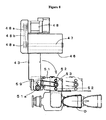
member 44 includes a pair of swivelingplates 51, asecond guide shaft 52 and asecond screw 53 provided between the swivelingplates 51, and a pair of holdingmembers 54 through which thesecond guide shaft 52 passes and with which thesecond screw 53 is threadedly engaged. The swivelingplates 51 are mounted rotatably around a rotation shaft 51a provided on theside plate portion 50 of thelongitudinal movement member 43. A spring 51b is arranged at either end of the rotation shaft 51a, and the swivelingplates 51 are urged so as to be set in a vertical position as shown in Fig. 7. - A
pressure receiving member 55 extends horizontally from the lower end of one swivelingplate 51. As described below, when thedrug conveying member 3 is moved to a predetermined position, thepressure receiving member 55 is pressurized by a pressurizing member provided in the device main body 1 (which, although not shown, corresponds to the pressurizing portion of the present invention). As a result, the swivelingplates 51, that is, the holdingmembers 44, rotate, making it possible to lay down the drug D being held between the holdingmembers 54. - Further, as shown in Fig. 9, at the lower end of the other swiveling
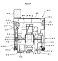
plate 51, there is provided afirst lock plate 56 so as to be capable of reciprocating while being urged in the horizontal direction (to the right in Fig. 9(a)) by a spring (not shown). Further, thefirst lock plate 56 is equipped with a roller 56a and a lock pin 56b. The roller 56a is pressurized by a protrusion 1a formed on the devicemain body 1, and reciprocates horizontally along the protrusion 1a. The lock pin 56b moves in alock hole 58 of asecond lock plate 57 integrated with the lower end portion of the swivelingplate 51. Thelock hole 58 is formed in a sector-shape, and a first lock recess 58b and a second lock recess 58c are formed at each of the ends of the arcuate portion 58a thereof. When the holdingmembers 44 descend, the roller 56a is pressurized by the protrusion 1a, and reciprocates against the urging force of the spring 51b, whereby the lock pin 56b is detached from the first lock recess 58b, and moves to the second lock recess 58c for engagement via the arcuate portion 58a. When the holdingmembers 44 ascend, the roller 56a is pressurized by the protrusion 1a, and reciprocates against the urging force of the spring 51b, whereby the lock pin 56b is detached from the second lock recess 58c, and moves to the first lock recess 58b via the arcuate portion 58a. - The
second guide shafts 52 are arranged on both sides on the same horizontal plane as thesecond screw 53. As a result, positional deviation in the rotational direction of the holdingmembers 54 with respect to thesecond screws 53 is prevented, and they move smoothly toward and away from each other while protruding horizontally. In thesecond screw 53, the thread forming direction differs between the right-hand and left-hand sides (e.g., the left half is formed as a right-hand screw, and the right half is formed as a left-hand screw). Further, thesecond screw 53 makes normal and reverse rotation via the pulleys 59a and the belt 59b through normal and reverse rotation of thesecond motor 59. As a result, the threaded engagement positions of the holdingmembers 54, which are threadedly engaged with thesecond screw 53, are changed, and the holdingmembers 54 make parallel movements toward and away from each other. - Each holding
member 54 is composed of an outer frame 54a adapted to guide in a rectangular form in side view in Fig. 5, and an elastic guide portion 54b integrated therein and held in press contact with the outer peripheral surface of the drug D. The elastic guide portion 54b is formed so as to exhibit a saw-tooth-like surface sectional configuration of the surface in contact with the drug D, thereby stabilizing the manner in which the drug D is held. - As shown in Fig. 1, the
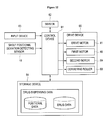
tray conveying line 4 is formed by a plurality of conveyingrollers 60 arranged at predetermined intervals in the horizontal direction. The conveyingrollers 60 are rotated by a motor or the like (not shown), and convey thetray 5 placed thereon. At one end of thetray conveying line 4, there is provided a stopper (not shown), causing the conveyedtray 5 to temporarily stop at a predetermined position and making it possible to dispense the drug D conveyed by thedrug conveying member 3. - As shown in the block diagram of Fig. 12, in the drug dispensing device constructed as described above, a
control device 61 makes reference to data stored in thestorage device 64 based on prescription data input from aserver 62 and aninput device 63, a detection signal from the shelf positionaldeviation detecting sensor 19, etc., and drive-controls drivedevices 65 such as motors. - The
storage device 64 stores various items of drug dispensing data. The drug dispensing data includes position data, drug data, map data, etc. Here, the position data implies the position of thecassette 26 in theshelf member 2, etc. The drug data implies the kind, remaining amount, configuration, etc. of the drugs D accommodated in eachshelf member 2. - The map data includes a container map and an article map (which, in this case, is a drugmap). The containermap is obtained by dividing the interior of the
tray 5 into which the drugs D are to be delivered into a plurality of virtual regions (hereinafter referred to as container virtual regions), and imparting an identification number to each container virtual region. In the example of the container map shown in Fig. 16, identification numbers "1" through "60" are imparted in columns starting from the left, with the numbers in each column being successively arranged from below to above. The container virtual regions are all of the same size, and the container map is stored in thestorage device 64 according to the kind oftray 5. Further, each container virtual region is associated with presence/absence data indicating whether a drug D accommodated is situated therein or not (For example, the presence data when a drug is present is indicated by the number "1", and the absence data when a drug is absent is indicated by the number "0"). - The article map is obtained by sectioning each drug D accommodated in the
tray 5 in the same size as the container virtual regions, and imparting an identification number to each virtual region (Hereinafter, the virtual regions of the drug map will be referred to as drug virtual regions) . As in the case of the container map, in the example of the drug map shown in Fig. 16, identification symbols "a" through "n" are imparted in columns successively starting from the left, with the symbols in each column being successively arranged from below to above. However, as shown in Fig. 17, when setting the drug virtual regions for the drug D, there is adopted a pattern which is enlarged from the center of the right-hand edge by an amount corresponding to one drug virtual region as compared with the actual size of the drug D (The protrusion at the center of the upper edge corresponds to the configuration of the drug D). The provision of the protrusion is effected for the following reason: when accommodating the drug D in thetray 5, if there is any drug D previously accommodated, it is necessary to avoid interference with this drug D1 previously accommodated with the drug D2 to be accommodated next (or interference with the holdingmembers 54 of thedrug grasping member 40 for holding the drug D2), and to accommodate the drugs D smoothly in thetray 5. - While in the above-described embodiment the container virtual regions and the drug virtual region are of the same size, they may also be of different sizes if the correlation between these regions is a definite one. For example, the container virtual region may be of a size corresponding to a combination of a plurality of drug virtual regions, or the drug virtual region may be of a size corresponding to a combination of a plurality of container virtual regions. Further, the size and configuration of each virtual region can be set freely (e.g., a triangular configuration). In brief, any setting will do as long as the correlation between the container virtual regions and the drug virtual region is definite, and it is possible to check through searching whether it is possible to accommodate a drug in the container.
- Next, the operation of the drug dispensing device, constructed as described above, will be illustrated with reference to the flowcharts of Figs. 13 and 14.
- When prescription data is input from the
server 62 or the input device 63 (Step S1), drug dispensing data stored in thestorage device 64 is read based on the input prescription data (Step S2). Then, based on the read drug dispensing data, thecassette 26 of theshelf member 2 from which the drug D included in the prescription data is to be extracted is determined (Step S3). Further, based on the configuration of the drug D included in the drug dispensing data, the distance between the holdingmembers 54 is previously determined at a value slightly larger than the width dimension of the drug D (Step S4). As a result, it is possible to hold the drug D with a requisite minimum operation, with thedrug grasping member 40 moved to a position immediately before the drug D, thus making it possible to reduce the operation time. Further, since the distance between the holdingmembers 54 with respect to the width dimension of the drug D can be set to a requisite minimum level, it is possible to arrange thecassettes 26 in eachshelf member 2 at the closest positions where they do not interfere with the holdingmembers 54. - Subsequently, the
drug conveying member 3 is driven to move thedrug grasping member 40 to theshelf member 2 accommodating the corresponding drugs D (Step S5). Then, when thedrug grasping member 40 moves to a position immediately before theshelf member 2 accommodating the corresponding drug D (Step S6), thefirst motor 48 is caused tomake normal rotation to cause thelongitudinal movement member 43 to advance (Step S7). Then, thesecond motor 59 is driven to hold the drug D with the holding members 54 (Step S8). - Here, a judgment is made as to whether the drug D has been properly held by the holding
members 54 or not (Step S9). This judgment is made by detecting the state in which electricity is supplied to thesecond motor 59, checking whether there is an excessive current or not. When there is an excessive current and, for example, the detected voltage value is in excess of a preset threshold value, it is judged that the drug D is being held by the holdingmembers 54. When the detected voltage value is not in excess of the threshold value, it is judged that nothing is being held by the holdingmembers 54. - When it is judged that the drug D is not being properly held by the holding
members 54, no drug D is judged to be accommodated in thecorresponding cassette 26, and drug deficiency is reported (Step S10). - Here, a judgment is made as to whether successive processing has been set or not (Step S11). When no successive processing has been set, the operation is stopped (Step S12); when it has been set, the procedure returns to Step S1, and the above-mentioned processing is repeated.
- When it is judged that the drug D has been properly held by the holding
members 54, thedrive motor 41 of thedrug conveying member 3 is driven to make normal rotation, and causes thedrug grasping member 40 to ascend, drawing the drug D held by the holdingmembers 54 from cassette 26 (Step S13). Then, thefirst motor 48 is driven to make reverse rotation, and thedrug grasping member 40 is returned to the position immediately before the cassette 26 (Step S14). At this time, within thecassette 26, the drug D advances while being pressurized by thepusher 31 that is urged by theconstant force spring 32. Thus, the drug D abuts the inner surface of the forward end of thecassette 26, and is automatically set ready for the next dispensing operation. - Subsequently, the
drug grasping member 40 is moved to a predetermined position in the tray conveying line 4 (Step S15). At this time, thetray 5 is conveyed along thetray conveying line 4, and is kept on standby at the above-mentioned position (Step S16). - In the
drug grasping member 40, immediately before reaching the above-mentioned predetermined position, the pressurizing member abuts thepressure receiving member 55, whereby the swivelingplates 51 swivel. The swiveling position for the swivelingplates 51 is below thelowermost shelf member 2, thus avoiding their interference with theshelf member 2. Thus, the drug D held by the holdingmembers 54 protrudes forwards while laid on its side and, starting herewith, the dispensing processing described below is executed (Step S17). As a result, it is possible for the drug D to be accommodated in thetray 5 while laid on its side while suppressing an increase in the longitudinal dimension of the space formed on the front side of theshelf member 2 inside the devicemain body 1. - When, from this onward, the dispensing of the drugs D included in the prescription data onto the
tray 5 is completed in the same manner, the stopping of thetray 5 by the stopper along thetray conveying line 4 is canceled, and thetray 5 is conveyed from the devicemain body 1 to the exterior (Step S18). - In this way, according to the drug dispensing device of this embodiment, the arrangement position for the
drug conveying member 3 and the position where theshelf 2 is drawn out to replenish thecassettes 26 with drugs D can be on the front side of the drugmain body 1, so sharing of the same space is possible, thereby enabling to form the device itself compact. Further, in thedrug conveying member 3, it is possible to swivel the holdingmembers 54 below theshelf member 2 situated lowermost to thereby dispense the drug D held onto thetray 5, so an increase in space formed between theshelf member 2 and the front surface of the devicemain body 1 can be suppressed. Further, theshelf member 2 can be drawn out obliquely downwards, so, even in the case of the first shelf member 2a situated uppermost, it is possible to easily perform the filling of thecassettes 26 with the drugs D. - The dispensing processing to dispense the drug D onto the
tray 5 by thedrug grasping member 40 is executed according to the flowcharts shown in Figs. 15A and 15B. - That is, the drug map is read from the
storage device 64 with respect to the drug D to be dispensed onto the tray 5 (Step S21) . Further, the container map of thetray 5 is read (Step S22). Then, it is checked whether there is any data of the search address in descending order of the identification numbers imparted to the container virtual regions (Step S23). When there is no data of the search address, all of the drug virtual regions are applied to the corresponding container virtual regions (Step S24), making a judgment as to whether arrangement is possible or not (Step S25) . - When any one of the corresponding virtual regions of the container map exhibits presence data and is judged to be not vacant, it is impossible to dispense a drug D to that position. When it is judged in Step S23 that there is data of the search address, or when it is judged in Step S25 that it is impossible to apply all of the drug virtual regions to the corresponding container virtual regions, a drug D cannot be arranged at that position. In view of this, 1 is added to the number i affixed to the address constituting the object of search (Step S28), and the procedures of Step S S23 through S25 are repeated until search is completed on all of the container virtual regions, that is, until i becomes 60 (Step S29) .
- When a space allowing arrangement of a drug D cannot be detected even after search has been completed on all of the container virtual regions, 1 is added to a stage t, and search processing is executed at a level one stage higher (Step S30). This processing is conducted within a range in which the number of stages s to be searched does not attain 4 (s < 4) (Step S31).
- Then, when it is judged that the corresponding container virtual regions are vacant for all the drug virtual regions, a judgment is made as to whether the upper stage is also vacant or not for all the container virtual regions judged to be vacant (Step S26) . That is, in the case in which this judgment is made at the first stage, a judgment is also made likewise for the second stage onward as to whether each container virtual region exhibits absence data or not (Step S32). This judgment from the second stage onward is also made since, when dispensing a plurality of kinds of drugs D of fixed priority order onto one
tray 5, a case is expected in which even when the first stage provides a vacant region, the second stage is not vacant. For example, when accommodating two kinds of drugs D of a rectangular configuration in plan view in two upper and lower stages, if the occupation area of the drug D accommodated in the first stage is smaller than that of the drug D accommodated in the second stage, there is a possibility that even if the first stage container virtual region exhibits absence data, the corresponding second stage virtual region exhibits presence data; this is why the judgment in Step S26 is made. - The judgment in Step S26 is similarly made even when the drug D has a height dimension covering a plurality of stages. In this case, however, it is also necessary to make a judgment as to whether the uppermost stage of the drug D can be accommodated in the
tray 5 or not. - This processing is conducted within a range in which the drug height is not in excess of the container height (Step S33). Here, search processing is conducted within a range in which the number of stages s to be searched does not attain 4 (s < 4).
- In this way, when it is determined that there is a space available allowing arrangement also in the height direction, dispensing of a drug D to that position is decided on (Step S27).
- When, in Step S S29 through S31, no space allowing arrangement of a drug D is detected until search has been conducted on all of the container virtual regions, or, when, in Step S33, no space allowing arrangement of a drug D in the height direction is detected, an error processing is executed, or transition is effected to dispensing onto the next tray (Step S34).
- As described above, also when the next drug D is to be dispensed onto the
same tray 5, search is conducted on the container virtual regions in descending order starting from the first position (i = 1), so, if the kind of drug differs or the dispensing order differs, it is possible to effect arrangement at high density. In particular, this dispensing control method proves effective in that it can be flexibly applied also to a case in which drugs D of different sizes and forms are to be dispensed. - More specifically, a case will be described in which the drugs (which, in this case, are drugs in the form of 500 ml bottles) of the drug map shown in Fig. 17 are to be dispensed into the
tray 5 of the container map shown in Fig. 16. When dispensing the first drug D1, all the container virtual regions are vacant. Thus, the first identification numbers/symbols in descending order (the container virtual region "1" and the drug virtual region "a") correspond to each other without fail, and the dispensing position is settled on the shaded portion in Fig. 18. - Subsequently, when dispensing the second drug D2, search of the container virtual regions of the container map in descending order shows that the identification symbol "a" of the drug virtual regions is applicable to the identification number "5". However, no drug virtual region exists at the position corresponding to the identification symbol "b". Thus, the dispensing position is not decided upon. If the identification symbol "a" is successively applied to the identification numbers "6" through "20", the dispensing position cannot be specified. By applying the identification symbol "a" of the drug virtual region to the identification number "21", it is possible to apply all the drug virtual regions of the drug map to the vacant regions of the container map. Thus, the dispensing position is settled upon this position.
- When dispensing the drugs D (which, in this case, are drugs in the form of 100 ml bottles) of the drug map shown in Fig. 19, the dispensing position for the second drug d2 is determined with respect to the first drug d1 as shown in Fig. 20. As a result, it is possible, instead of dispensing the drugs in a single horizontal row, to dispense them while alternately shifting their positions in the vertical direction. That is, the drugs D are accommodated at high density in the limited space in the
tray 5. - The operation of dispensing the drugs D onto the
tray 5 is conducted as described above. In the case where thetray 5 is of a construction allowing accommodation of the drugs D in a plurality of stages, when no drug D can be accommodated in the first stage, detection of a vacant region is conducted in the same manner for the second stage onwards to settle on the dispensing position. - When there exists no more drug D in the
shelf member 2, theshelf member 2 is drawn out to replenish it with drugs D. That is, by pulling thelock member 23, thelock portion 24 thereof is detached from the locking/receivingportion 17 of the devicemain body 1, and theshelf member 2 is drawn out by grasping thegrip 22. As shown in Fig. 2 or 3, in the case where the shelf to be drawn out is theuppermost shelf member 2, it is possible to tilt the forward, drawn-out side thereof downwardly after drawing it out of the devicemain body 1. More specifically, when theshelf member 2 is pulled by grasping thegrip 22, thefirst rail portion 13 and thesecond rail portion 14 expand successively on the side wall, and theguide roller 25 slides on thefirst guide surface 9, whereby theshelf member 2 moves horizontally toward the front side. When theguide roller 25 reaches thesecond guide surface 10, the guide by thefirst guide surface 9 is lost, so theshelf member 2 can be rotated around thesupport shaft 16. Thus, when theshelf member 2 is rotated against the urging force of the spring 16a, theguide roller 25 rolls on thesecond guide surface 10, and the drawn-out side (forward end side) is tilted so as to be downwardly oblique. By being tilted to a predetermined position, theshelf member 2 is prevented from rotating by thelock member 23, so thecassettes 26 are filled with drugs D. - In accommodating drugs D in the
cassette 26, thepusher 31 of thedrug extraction member 30 is pressed and moved toward the rear end against the urging force of theconstant force spring 32, and thelock claw 37 of thelock lever 33 is locked to thelock hole 29 formed on the back side of thecassette 26. When the replenishment of thecassette 26 with the drug D is completed, thelock lever 33 is operated to detach thelock claw 37 from thelock hole 29, and the drug D is moved to the front side of thecassette 26 by the urging force of theconstant force spring 32 for alignment. -
- Fig. 1 is a front view of a drug supply device according to this embodiment of the present invention.
- Fig. 2 is a side view of Fig. 1.
- Fig. 3 includes portion (a) showing a detailed view of the draw-out structure of the shelf member of Fig. 2, and portion (b) showing an enlarged partial side sectional view.
- Fig. 4 includes portion (a) showing a sectional view of a cassette arranged in the shelf member shown in Fig. 3, and portion (b) showing a side sectional view thereof.
- Fig. 5 is a front view of the holding member shown in Fig. 1.
- Fig. 6 is a rear view of Fig. 5.
- Fig. 7 is a side view of Fig. 5.
- Fig. 8 is a diagram showing how the swiveling plate is rotated from the position of Fig. 7.
- Fig. 9 is a diagram showing how the swiveling plate is swiveled.
- Figs. 10 are diagrams showing examples of the drug accommodated in the cassette.
- Fig. 11 is a schematic explanatory view illustrating how the horizontal guide bar shown in Fig. 1 is driven.
- Fig. 12 is a block diagram showing the drug supply device of this embodiment of the present invention.
- Fig. 13 is a flowchart illustrating the operation of the drug supply device of this embodiment of the present invention.
- Fig. 14 is a flowchart illustrating the operation of the drug supply device of this embodiment of the present invention.
- Fig. 15A is a flowchart illustrating the dispensing processing of Fig. 14.
- Fig. 15B is a flowchart illustrating the dispensing processing of Fig. 14.
- Fig. 16 is a diagram showing an example of the container map.
- Fig. 17 is a diagram showing an example of the drug map.
- Fig. 18 is a diagram illustrating how the drug map shown in
- Fig. 17 is applied to the container map of Fig. 16.
- Fig. 19 is a diagram showing another example of the drug map.
- Fig. 20 is a diagram illustrating how the drug map shown in Fig. 19 is applied to the container map of Fig. 16.
-
- 1:
- device main body
- 2:
- shelf member
- 2a:
- first shelf member
- 2b:
- second shelf member
- 3:
- drug conveying member (dispensing means)
- 4:
- tray conveying line
- 5:
- tray
- 6:
- guide member
- 6a:
- first guide member
- 6b:
- second guide member
- 7:
- guide wall
- 7a:
- guide groove,
- 8:
- guide rail
- 9:
- first guide surface
- 10:
- second guide surface
- 11:
- support roller
- 12:
- lock protrusion
- 13:
- first rail portion
- 14:
- second rail portion
- 15:
- support wall
- 15a:
- abutment/receiving portion
- 16:
- support shaft
- 16a:
- spring
- 17:
- locking/receiving portion
- 18:
- support rail portion
- 19:
- shelf positional deviation detecting sensor
- 20:
- box body
- 21:
- drug accommodating portion
- 22:
- grip
- 23:
- lock member
- 24:
- lock portion
- 25:
- guide roller
- 26:
- cassette
- 27:
- groove portion
- 28:
- support plate
- 29:
- lock hole
- 30:
- drug extrusion member
- 30a:
- casing
- 31:
- pusher
- 31a:
- protrusion
- 32:
- constant force spring
- 33:
- lock lever
- 34:
- drum
- 35:
- spring portion
- 36:
- operating portion
- 37:
- lock claw
- 38:
- horizontal guide bar
- 39:
- vertical guide bar
- 40:
- drug grasping member
- 41:
- drive motor
- 41a:
- pulley
- 41b:
- belt
- 42:
- support member
- 43:
- longitudinal movement member
- 44:
- holding member
- 45:
- guide receiving portion
- 46:
- first guide shaft
- 47:
- first screw
- 48:
- first motor
- 48a:
- pulley
- 48b:
- belt
- 49:
- slide stand
- 49a:
- roller
- 50:
- side plate portion
- 51:
- swiveling plate
- 52:
- second guide shaft
- 53:
- second screw
- 54:
- holding member
- 54a:
- outer frame
- 54b:
- elastic guide portion
- 55:
- pressure receiving member
- 56:
- first lock plate
- 56a:
- roller
- 56b:
- lock pin
- 57:
- second lock plate
- 58:
- lock hole
- 58a:
- arcuate portion
- 58b:
- first lock recess
- 58c:
- second lock recess
- 59:
- second motor
- 59a:
- pulley
- 59b:
- belt
- 60:
- conveying roller
- 61:
- control device (control means)
- 62:
- server
- 63:
- input device
- 64:
- storage device
- 65:
- drive device
- D:
- drug
- d1:
- body portion
- d2:
- leg portion
Claims (5)
- An article dispensing device comprising:a dispensing means for holding and dispensing an article into a container;a storage means for storing a container map prepared by dividing an internal space of the container into a plurality of container virtual regions, and an article map prepared by dividing the article into a plurality of article virtual regions that are in a predetermined correlation with the container virtual regions; anda controlmeans which calls, from the storage means, the article map of the article to be dispensed by the dispensing means and the container map of the container for accommodating the article, which searches for a vacant region by searching each container virtual region of the container map in a predetermined order, which specifies a dispensing position for the article according to the article map, and which drive-controls the dispensing means based on the specified dispensing position for causing the article held to be accommodated in the container.
- An article dispensing device according to Claim 1, wherein the predetermined correlation implies that the container virtual regions and the article virtual regions are of the same size.
- An article dispensing device according to Claim 1 or 2, wherein the article map stored in the storage means is equipped with at least a stick-out region corresponding to one article virtual region as compared with the actual article size.
- An article dispensing device according to one of Claims 1 through 3, wherein the container has an internal space capable of accommodating articles vertically in a plurality of stages,
wherein the container map stored in the storage means is formed by a container virtual space formed of a three-dimensional space sectioned also vertically in correspondence with the accommodation structure of the container, with the article map being formed by an article virtual space of the same size as the container virtual space, and
wherein, when it is judged that the article map of the article to be contained in the container occupies a plurality of vertically sectioned container virtual spaces of the container map, the control means searches for a vacant region in the container map, and, after checking for a vacant region on a lowermost stage, also checks for a vacant region on a corresponding upper stage, and settles on a dispensing position only when it is judged that vacant regions exist on both stages. - An article dispensing method comprising:preparing a container map by dividing an internal space of a container into which an article is to be dispensed for accommodation into container virtual regions;preparing an article map by dividing the article into article virtual regions of the same size as the container virtual regions;searching for a vacant region by searching the container virtual regions of the container map in a predetermined order based on the article map of the article to be dispensed and the container map of the container for accommodating the article; andspecifying a dispensing position for the article according to the article map, the article being dispensed at the dispensing position.
Applications Claiming Priority (3)
| Application Number | Priority Date | Filing Date | Title |
|---|---|---|---|
| JP2005006390 | 2005-01-13 | ||
| JP2006002534A JP5119593B2 (en) | 2005-01-13 | 2006-01-10 | Article dispensing apparatus, method, and medicine dispensing apparatus |
| PCT/JP2006/300165 WO2006075583A1 (en) | 2005-01-13 | 2006-01-11 | Article dispensing device and method |
Publications (2)
| Publication Number | Publication Date |
|---|---|
| EP1857382A1 true EP1857382A1 (en) | 2007-11-21 |
| EP1857382A4 EP1857382A4 (en) | 2012-10-17 |
Family
ID=36677608
Family Applications (1)
| Application Number | Title | Priority Date | Filing Date |
|---|---|---|---|
| EP06711514A Withdrawn EP1857382A4 (en) | 2005-01-13 | 2006-01-11 | Article dispensing device and method |
Country Status (6)
| Country | Link |
|---|---|
| US (1) | US7822505B2 (en) |
| EP (1) | EP1857382A4 (en) |
| JP (1) | JP5119593B2 (en) |
| KR (1) | KR20070112110A (en) |
| CN (1) | CN101102947B (en) |
| WO (1) | WO2006075583A1 (en) |
Cited By (3)
| Publication number | Priority date | Publication date | Assignee | Title |
|---|---|---|---|---|
| WO2009045685A3 (en) * | 2007-09-28 | 2009-05-22 | Coca Cola Co | Package advancement system |
| ITNA20090078A1 (en) * | 2009-12-18 | 2011-06-19 | Marco Cervizzi | ELECTROMECHANICAL STORAGE, MANAGEMENT AND DISTRIBUTION SYSTEM ON AUTONOMOUS TRACKS OF DRUGS OR SIMILAR INSIDE AND OUTSIDE OF PHARMACIES CONFIGURABLE WITH SELF H-24 SALES SYSTEM. |
| US8146753B2 (en) * | 2006-03-27 | 2012-04-03 | Yuyama Mfg. Co., Ltd. | Medicine cart |
Families Citing this family (22)
| Publication number | Priority date | Publication date | Assignee | Title |
|---|---|---|---|---|
| US20080142537A1 (en) * | 2006-12-14 | 2008-06-19 | The Coca-Cola Company | First in First Out Vending Systems |
| JP5013978B2 (en) * | 2007-06-11 | 2012-08-29 | サンデン株式会社 | vending machine |
| JP5434420B2 (en) * | 2008-09-19 | 2014-03-05 | 株式会社湯山製作所 | Drug dispensing apparatus and drug dispensing method |
| WO2011094676A1 (en) * | 2010-01-29 | 2011-08-04 | Mechtronics Corporation | Theft deterrent system for product display device |
| CN102862774B (en) * | 2011-07-08 | 2015-06-24 | 段斐然 | Automatic article management and access device |
| CN102602639B (en) * | 2012-03-15 | 2014-04-16 | 江苏迅捷装具科技有限公司 | Device and method for storage and distribution based on arrangement of largest sides contact of boxed products |
| US9150119B2 (en) | 2013-03-15 | 2015-10-06 | Aesynt Incorporated | Apparatuses, systems, and methods for anticipating and delivering medications from a central pharmacy to a patient using a track based transport system |
| US9511945B2 (en) | 2012-10-12 | 2016-12-06 | Aesynt Incorporated | Apparatuses, systems, and methods for transporting medications from a central pharmacy to a patient in a healthcare facility |
| KR102274422B1 (en) * | 2013-01-18 | 2021-07-07 | 가부시키가이샤 유야마 세이사쿠쇼 | Drug delivery device, drug delivery method, drug delivery program, and recording medium |
| US9390575B1 (en) * | 2013-12-12 | 2016-07-12 | Anytime Propane, Llc | Canister distribution system |
| CN112133448A (en) * | 2014-08-22 | 2020-12-25 | 株式会社汤山制作所 | Medicine sorting device |
| GB2544648A (en) * | 2015-11-11 | 2017-05-24 | Ocado Innovation Ltd | Storage containers, bins and devices |
| CA2997418C (en) * | 2015-12-04 | 2021-06-22 | Signifi Solutions Inc. | Automated vending machine with tray transport system |
| US10078933B2 (en) | 2016-06-22 | 2018-09-18 | Anytime Propane, Llc | Semi-automated canister distribution system and method |
| CN106144378B (en) * | 2016-06-29 | 2018-09-14 | 苏州信亨自动化科技有限公司 | Bottled medicament automatic medicine-dispensing device |
| CN106742098B (en) * | 2017-01-09 | 2023-09-26 | 成都宇亨智能科技有限公司 | Multilayer medicine machine frame that goes down |
| EP3398630A1 (en) | 2017-05-03 | 2018-11-07 | Sanofi-Aventis Deutschland GmbH | Auto-injector storage device |
| CN109422057A (en) * | 2017-09-04 | 2019-03-05 | 上银科技股份有限公司 | Automatic storage operation method |
| EP4180340B1 (en) * | 2020-10-27 | 2025-05-21 | PHC Holdings Corporation | Chemical agent supply device and chemical agent supply method |
| JP7697668B2 (en) * | 2021-08-02 | 2025-06-24 | 株式会社タカゾノ | Drug Delivery Device |
| CN114403648B (en) * | 2022-02-28 | 2022-11-11 | 安阳工学院 | Automatic medicine distribution device and medicine distribution method |
| US20240203571A1 (en) * | 2022-12-16 | 2024-06-20 | Vetsnap Corp. | Systems and techniques for managing controlled substance inventory data |
Family Cites Families (50)
| Publication number | Priority date | Publication date | Assignee | Title |
|---|---|---|---|---|
| US5292029A (en) * | 1989-11-08 | 1994-03-08 | Pearson Walter G | Patient medication dispensing and associated record |
| JPH0741568B2 (en) * | 1988-09-20 | 1995-05-10 | 鐘紡株式会社 | Teaching data creation device for boxed robot |
| US5175692A (en) * | 1989-04-14 | 1992-12-29 | University Of Cincinnati | Method and apparatus for palletizing randomly arriving mixed size and content parcels |
| JPH03242147A (en) | 1990-02-20 | 1991-10-29 | Shoji Yuyama | Tablet stock managing method for tablet packaging machine |
| US5337919A (en) | 1993-02-11 | 1994-08-16 | Dispensing Technologies, Inc. | Automatic dispensing system for prescriptions and the like |
| JP2933837B2 (en) | 1994-10-21 | 1999-08-16 | 株式会社湯山製作所 | Drug packaging device |
| JPH08225117A (en) * | 1994-12-22 | 1996-09-03 | Honda Motor Co Ltd | Storage control method and storage control device in automatic warehouse |
| JPH08231013A (en) * | 1994-12-27 | 1996-09-10 | Honda Motor Co Ltd | Abnormality processing method and abnormality processing device by touch panel type monitor |
| US5771657A (en) | 1996-05-07 | 1998-06-30 | Merck Medco Managed Care, Inc. | Automatic prescription filling, sorting and packaging system |
| JPH1077107A (en) | 1996-09-02 | 1998-03-24 | Ishida Co Ltd | Product sorting device |
| US5930145A (en) | 1996-12-03 | 1999-07-27 | Yuyama Mfg. Co., Ltd. | Method for medicament stock management by transponders and apparatus therefor |
| JP4318766B2 (en) * | 1997-06-17 | 2009-08-26 | 株式会社湯山製作所 | Tablet filling equipment |
| US6006946A (en) | 1997-12-05 | 1999-12-28 | Automated Prescriptions System, Inc. | Pill dispensing system |
| JPH11208604A (en) * | 1998-01-23 | 1999-08-03 | Hitachi Zosen Corp | How to determine the storage position of the object in the storage body |
| US6256967B1 (en) | 1998-08-27 | 2001-07-10 | Automed Technologies, Inc. | Integrated automated drug dispenser method and apparatus |
| JP2000103404A (en) | 1998-09-29 | 2000-04-11 | Sanyo Electric Co Ltd | Medicine feed device |
| US6170230B1 (en) * | 1998-12-04 | 2001-01-09 | Automed Technologies, Inc. | Medication collecting system |
| US6883681B1 (en) * | 1998-12-10 | 2005-04-26 | Scriptpro Llc | Automatic dispensing system for unit medicament packages |
| CA2400478A1 (en) | 2000-02-15 | 2001-10-18 | Yong-Nam Park | The extended order communication system based on internet and method thereof |
| US6755322B1 (en) * | 2000-02-22 | 2004-06-29 | Hettie J. Herzog | Automated shopping system and apparatus |
| US6748295B2 (en) * | 2000-07-26 | 2004-06-08 | Northrop Grumman Corporation | Item delivery and retrieval system |
| JP2002120913A (en) | 2000-10-17 | 2002-04-23 | Matsushita Electric Ind Co Ltd | Assignment system and assignment method |
| JP2002126044A (en) | 2000-10-24 | 2002-05-08 | Rikogaku Shinkokai | Chemical administration device and centralized administration information processor |
| JP4553505B2 (en) | 2001-03-16 | 2010-09-29 | 株式会社トーショー | Dispensing system |
| JP4551584B2 (en) * | 2001-03-30 | 2010-09-29 | 株式会社湯山製作所 | Infusion bottle supply device |
| JP3722024B2 (en) | 2001-07-31 | 2005-11-30 | 株式会社寺岡精工 | Sales data processor |
| JP2003118816A (en) | 2001-10-18 | 2003-04-23 | Ishida Co Ltd | Product storage instruction device, product storage instruction method, and product storage instruction program |
| JP2003146414A (en) | 2001-11-05 | 2003-05-21 | Kintetsu World Express Inc | Return warehousing system |
| KR100972347B1 (en) * | 2001-11-09 | 2010-07-26 | 가부시키가이샤 유야마 세이사쿠쇼 | Ampoule storage container |
| JP4159783B2 (en) | 2002-01-16 | 2008-10-01 | 株式会社湯山製作所 | Dispensing system |
| JP2003237703A (en) | 2002-02-20 | 2003-08-27 | Sanyo Electric Co Ltd | Medicine feeding apparatus |
| JP2003237711A (en) | 2002-02-20 | 2003-08-27 | Sanyo Electric Co Ltd | Medicine feeding apparatus |
| WO2003073237A2 (en) * | 2002-02-26 | 2003-09-04 | Munroe Chirnomas | Programming presets in a vending machine |
| JP3373503B2 (en) | 2002-04-12 | 2003-02-04 | 株式会社湯山製作所 | Drug packaging device |
| US7303094B2 (en) | 2002-08-09 | 2007-12-04 | Kevin Hutchinson | Vacuum pill dispensing cassette and counting machine |
| US7228198B2 (en) | 2002-08-09 | 2007-06-05 | Mckesson Automation Systems, Inc. | Prescription filling apparatus implementing a pick and place method |
| JP2004157579A (en) | 2002-11-01 | 2004-06-03 | Tadanori Munemoto | Work management system for dispensing pharmacy |
| JP3945700B2 (en) | 2002-12-12 | 2007-07-18 | 株式会社トーショー | Chemical storage device |
| JP2004256242A (en) | 2003-02-26 | 2004-09-16 | Matsushita Electric Ind Co Ltd | Storage device |
| JP2004318829A (en) * | 2003-03-28 | 2004-11-11 | Sanden Corp | Vending machine |
| US7123989B2 (en) * | 2003-07-01 | 2006-10-17 | Asteres, Inc. | System and method for providing a random access and random load dispensing unit |
| US20050192705A1 (en) * | 2003-07-01 | 2005-09-01 | Asteres Inc. | Random access and random load dispensing unit |
| US7584016B2 (en) * | 2003-09-30 | 2009-09-01 | Intrinsic Marks International Llc | Item monitoring system and methods |
| JP2005122360A (en) | 2003-10-15 | 2005-05-12 | Casio Comput Co Ltd | Medical data processing apparatus and medical data processing program |
| JP4484527B2 (en) | 2004-01-05 | 2010-06-16 | 株式会社トーショー | Automatic dispensing device |
| EP2719368B1 (en) | 2004-01-05 | 2019-06-26 | Tosho Inc. | Drug feeder and assembly thereof |
| US7234609B2 (en) * | 2004-04-15 | 2007-06-26 | Redbox Automated Retail, L.L.C. | Article dispensing system and method for same |
| US8438067B2 (en) * | 2004-09-03 | 2013-05-07 | Tosho Inc. | Medical resource storage and management apparatus and medical supply management system |
| JP4821130B2 (en) | 2005-02-16 | 2011-11-24 | 株式会社湯山製作所 | Tablet filling equipment |
| JP2006230763A (en) | 2005-02-25 | 2006-09-07 | Yuyama Manufacturing Co Ltd | Tablet filling apparatus |
-
2006
- 2006-01-10 JP JP2006002534A patent/JP5119593B2/en not_active Expired - Fee Related
- 2006-01-11 EP EP06711514A patent/EP1857382A4/en not_active Withdrawn
- 2006-01-11 WO PCT/JP2006/300165 patent/WO2006075583A1/en not_active Ceased
- 2006-01-11 CN CN2006800023276A patent/CN101102947B/en not_active Expired - Fee Related
- 2006-01-11 KR KR1020077014901A patent/KR20070112110A/en not_active Ceased
- 2006-01-11 US US11/795,179 patent/US7822505B2/en not_active Expired - Fee Related
Cited By (3)
| Publication number | Priority date | Publication date | Assignee | Title |
|---|---|---|---|---|
| US8146753B2 (en) * | 2006-03-27 | 2012-04-03 | Yuyama Mfg. Co., Ltd. | Medicine cart |
| WO2009045685A3 (en) * | 2007-09-28 | 2009-05-22 | Coca Cola Co | Package advancement system |
| ITNA20090078A1 (en) * | 2009-12-18 | 2011-06-19 | Marco Cervizzi | ELECTROMECHANICAL STORAGE, MANAGEMENT AND DISTRIBUTION SYSTEM ON AUTONOMOUS TRACKS OF DRUGS OR SIMILAR INSIDE AND OUTSIDE OF PHARMACIES CONFIGURABLE WITH SELF H-24 SALES SYSTEM. |
Also Published As
| Publication number | Publication date |
|---|---|
| WO2006075583A1 (en) | 2006-07-20 |
| EP1857382A4 (en) | 2012-10-17 |
| CN101102947A (en) | 2008-01-09 |
| US20080083769A1 (en) | 2008-04-10 |
| JP2006219299A (en) | 2006-08-24 |
| JP5119593B2 (en) | 2013-01-16 |
| KR20070112110A (en) | 2007-11-22 |
| US7822505B2 (en) | 2010-10-26 |
| CN101102947B (en) | 2011-04-13 |
Similar Documents
| Publication | Publication Date | Title |
|---|---|---|
| US7822505B2 (en) | Article dispensing device and method | |
| KR101182088B1 (en) | Medicine dispensing device | |
| JP4551396B2 (en) | Chemical dispensing device | |
| KR101743412B1 (en) | Medication dispensing device | |
| CN104144857B (en) | medicine box | |
| US6513677B1 (en) | Apparatus and method for vending products | |
| JP2009000290A (en) | Tablet filling apparatus | |
| JP5092568B2 (en) | Tablet filling equipment | |
| JP2009000291A5 (en) | ||
| JP4782170B2 (en) | Tablet filling equipment | |
| JP2009023731A (en) | Tablet filling device | |
| JP5566140B2 (en) | Vending machine product storage and conveyance device | |
| JP4964199B2 (en) | Individual packaging medicine automatic supply equipment | |
| EP3525183A1 (en) | Dispenser device | |
| JP2022009264A (en) | Medicine packing unit | |
| JP2023021674A (en) | Medicine feeding device | |
| KR20120126212A (en) | System for automatic storage and taking out of chartula | |
| JP5648794B2 (en) | Drug dispensing device | |
| JP5648794B6 (en) | Drug dispensing device | |
| JP2018102405A (en) | Dispensing device | |
| JP2023021673A (en) | drug supply device | |
| JP5648793B6 (en) | Drug dispensing device | |
| JP5648793B2 (en) | Drug dispensing device | |
| JP2003233868A (en) | Article extrusion method and apparatus |
Legal Events
| Date | Code | Title | Description |
|---|---|---|---|
| PUAI | Public reference made under article 153(3) epc to a published international application that has entered the european phase |
Free format text: ORIGINAL CODE: 0009012 |
|
| 17P | Request for examination filed |
Effective date: 20070724 |
|
| AK | Designated contracting states |
Kind code of ref document: A1 Designated state(s): AT BE BG CH CY CZ DE DK EE ES FI FR GB GR HU IE IS IT LI LT LU LV MC NL PL PT RO SE SI SK TR |
|
| DAX | Request for extension of the european patent (deleted) | ||
| A4 | Supplementary search report drawn up and despatched |
Effective date: 20120917 |
|
| RIC1 | Information provided on ipc code assigned before grant |
Ipc: G07F 17/00 20060101ALI20120911BHEP Ipc: G07F 11/38 20060101ALI20120911BHEP Ipc: G06Q 50/22 20120101ALI20120911BHEP Ipc: B65B 5/10 20060101ALI20120911BHEP Ipc: B65G 1/137 20060101ALI20120911BHEP Ipc: G07F 11/16 20060101AFI20120911BHEP |
|
| 17Q | First examination report despatched |
Effective date: 20130814 |
|
| STAA | Information on the status of an ep patent application or granted ep patent |
Free format text: STATUS: THE APPLICATION HAS BEEN WITHDRAWN |
|
| 18W | Application withdrawn |
Effective date: 20180202 |
|
| RIC1 | Information provided on ipc code assigned before grant |
Ipc: G07F 11/38 20060101ALI20120911BHEP Ipc: B65G 1/137 20060101ALI20120911BHEP Ipc: G07F 11/16 20060101AFI20120911BHEP Ipc: G07F 17/00 20060101ALI20120911BHEP Ipc: B65B 5/10 20060101ALI20120911BHEP Ipc: G06Q 50/22 20180101ALI20120911BHEP |
|
| RIC1 | Information provided on ipc code assigned before grant |
Ipc: G07F 17/00 20060101ALI20120911BHEP Ipc: G07F 11/38 20060101ALI20120911BHEP Ipc: G06Q 50/22 20180101ALI20120911BHEP Ipc: B65G 1/137 20060101ALI20120911BHEP Ipc: G07F 11/16 20060101AFI20120911BHEP Ipc: B65B 5/10 20060101ALI20120911BHEP |