EP1857315A2 - Power transmission, in particular for a motor vehicle - Google Patents
Power transmission, in particular for a motor vehicle Download PDFInfo
- Publication number
- EP1857315A2 EP1857315A2 EP07009140A EP07009140A EP1857315A2 EP 1857315 A2 EP1857315 A2 EP 1857315A2 EP 07009140 A EP07009140 A EP 07009140A EP 07009140 A EP07009140 A EP 07009140A EP 1857315 A2 EP1857315 A2 EP 1857315A2
- Authority
- EP
- European Patent Office
- Prior art keywords
- freewheel
- rotor
- drive
- planetary gear
- drive train
- Prior art date
- Legal status (The legal status is an assumption and is not a legal conclusion. Google has not performed a legal analysis and makes no representation as to the accuracy of the status listed.)
- Withdrawn
Links
Images

Classifications
-
- F—MECHANICAL ENGINEERING; LIGHTING; HEATING; WEAPONS; BLASTING
- F16—ENGINEERING ELEMENTS AND UNITS; GENERAL MEASURES FOR PRODUCING AND MAINTAINING EFFECTIVE FUNCTIONING OF MACHINES OR INSTALLATIONS; THERMAL INSULATION IN GENERAL
- F16H—GEARING
- F16H3/00—Toothed gearings for conveying rotary motion with variable gear ratio or for reversing rotary motion
- F16H3/44—Toothed gearings for conveying rotary motion with variable gear ratio or for reversing rotary motion using gears having orbital motion
- F16H3/46—Gearings having only two central gears, connected by orbital gears
- F16H3/48—Gearings having only two central gears, connected by orbital gears with single orbital gears or pairs of rigidly-connected orbital gears
- F16H3/52—Gearings having only two central gears, connected by orbital gears with single orbital gears or pairs of rigidly-connected orbital gears comprising orbital spur gears
- F16H3/56—Gearings having only two central gears, connected by orbital gears with single orbital gears or pairs of rigidly-connected orbital gears comprising orbital spur gears both central gears being sun gears
Definitions
- the invention relates to a drive train, in particular for a motor vehicle, having a drive shaft having an internal combustion engine and thus in drive connection, a rotor having an electric machine which is operable as a generator in a first mode and in a second mode as a motor, wherein between the Drive shaft and the rotor, a power transmission unit is arranged, which has two acting in opposite directions freewheels and a planetary gear, wherein the drive shaft is in drive operation in generator mode via a first freewheel and in engine operation via the planetary gear and a second freewheel with the rotor.
- Such a drive train which has a reciprocating internal combustion engine as an internal combustion engine, is off WO 00/13927 known.
- the electric machine of the drive train serves on the one hand as a starter for reciprocating internal combustion engine and on the other hand as an alternator, which converts the kinetic energy generated by the reciprocating internal combustion engine into electrical energy when operating reciprocating internal combustion engine, for example, to charge a vehicle battery and / or provided in the motor vehicle electrical consumers Supply electricity.
- the electric machine is connected via a first freewheel directly to a transmission disc, which is connected via a rotating belt with a drive shaft arranged on the drive wheel in drive connection.
- the freewheel the average rotational speed of the rotor of the electric machine is slightly larger than the average rotational speed of the crankshaft of the reciprocating internal combustion engine.
- a planetary gear is disposed between the electric machine and the reciprocating internal combustion engine, which is coupled to the transmission disc via a second freewheel during engine operation of the electric machine.
- the planetary gear has a rotatably connected to the rotor of the electric machine sun gear, which is connected via a planetary gear set with a fixed ring gear.
- a web carrying the planet gears drives the transmission disk via the second freewheel.
- the first freewheel transmits the torque and the second freewheel is over-turned.
- the powertrain has proven itself in practice, it still points Disadvantages.
- the electric machine can not be used as an additional drive motor for the drive train, for example in order to increase the drive torque during acceleration of the motor vehicle (booster function).
- a drive train with an internal combustion engine having a drive shaft and an electric machine having a rotor in connection therewith, which is operable as a generator in a first operating mode and as a motor in a second operating mode, wherein between the drive shaft and the rotor a power transmission unit is arranged, which has two acting in opposite directions freewheels and a planetary gear, wherein the drive shaft in generator operation via a first freewheel and in motor operation via the planetary gear and a second freewheel with the rotor is in driving connection, and wherein the planetary gear two, one having different number of teeth having sun gears and at least one meshing with two sun gears planetary gear.
- the two sun wheels connected to one another via the at least one planetary gear result in a low gear ratio of the planetary gear, so that the electric machine can be switched between the generator mode and the engine mode during operation of the internal combustion engine in order to enable a booster function.
- the electrical machine located in generator mode needs to be accelerated only slightly, so that the first freewheel over-revving and locks the second freewheel.
- the rotational speed of the electric machine is reduced only slightly when switching from engine operation to generator operation, so that the electric machine can be used immediately after the engine operation as a generator. Since the freewheels partially compensate for speed irregularities of the reciprocating internal combustion engine, a significantly lower wear of the belt results compared to an electric machine firmly coupled to the transmission disk.
- sun gears have a different pitch circle diameter, and if the profiles of the teeth of the sun gears are shifted to each other such that both sun gears have the same module. In the production of sun gears then only a single gear tool is needed.
- the electric machine and the power transmission unit thereby form a belt-driven starter generator with vibration isolation and traction.
- the first sun gear has an inner cavity, and if the second freewheel is arranged in the inner cavity.
- the power transmission unit can then have very compact dimensions.
- the second freewheel on an inner and an outer freewheel ring, wherein the inner freewheel ring is rotatably connected to a housing part of the electric machine and the outer freewheel ring with a web on which the at least one planet gear is rotatably mounted. Also by this measure, a compact design of the power transmission unit is made possible.
- a wall region of the web remote from the outer freewheel ring is preferably supported by means of a slide bearing on an inner circumferential wall of the first sunwheel which delimits the inner cavity.
- the power transmission unit then allows a short design and a rigid construction.
- the second sun gear is designed like a ring gear, and if the first freewheel is arranged in an inner space bounded by the second sun gear. Also by this measure a short design and a rigid construction of the power transmission unit can be achieved.
- the electric machine needs only slightly accelerated or decelerated when switching between generator and engine operation.
- the ring gears have a different pitch circle diameter, and if the profiles of the teeth of the ring gears are shifted to each other such that both ring gears have the same module. In the production of the ring gears only a single gear tool is then required.
- the transmission ratio of the planetary gear is between 1.02 and 1.07, in particular between 1.03 and 1.06 and preferably between 1.04 and 1.05.
- the second freewheel and in engine operation, the first freewheel is outperformed in practice in most reciprocating engines in generator mode.
- the gear ratio is chosen as low as possible so that the electric machine without having to be significantly accelerated or decelerated, can be switched between the generator and engine operation.
- a drive train for a motor vehicle has a known internal combustion engine designed as a reciprocating internal combustion engine and an electric machine operatively connected thereto, which can be operated as a generator in a first operating mode and as a motor in a second operating mode.
- the internal combustion engine has a drive shaft rotatably mounted on an engine block, on which a drive wheel is arranged, which is connected via a revolving belt with a transmission disk 1 of a disposed in a power transmission path between the internal combustion engine and the electric machine power transmission unit 2 in drive connection.
- the transmission disc 1 on its outer periphery on a wave-shaped profiling 3, which comes to a matching profiling of the belt not shown in detail in the drawing to rest.
- the electric machine has a stator with a winding and a rotor rotatably mounted thereon, which magnetically interacts with the stator via an air gap.
- the rotor has a rotor shaft 4, on which the power transmission unit 2 is arranged.
- the power transmission unit 2 has two freewheels 5, 6 acting in opposite directions and a planetary gear.
- the drive shaft is connected via a first freewheel 5 and in motor operation via the planetary gear and a second freewheel 6 with the rotor in drive connection.
- the first freewheel 5 overrun in engine operation and the second freewheel 6 in the generator mode.
- the planetary gear has two sun gears 7, 8 and a set of planet gears 9.
- the planetary gears 9 each have a continuous toothing over their length. A first portion of the toothing meshes each with a first sun gear 7 and a second portion of the toothing with a second sun gear 8.
- the sun gears 7, 8 have the same module, but a different number of teeth and thus a different pitch circle diameter.
- the first sun gear 7 is rotatably connected to the rotor shaft 4 and the second sun gear 8 rotatably connected to the transmission disk 1.
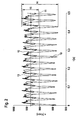
- crankshaft speed signal 10 Based on the graphically represented in Fig. 2 the crankshaft speed signal 10 is evident that the rotational speed of the crankshaft has deformities min -1 and fluctuates about a mean 11 in an interval between about 840 and 970 min -1. Due to the first freewheel 5, the speed irregularities of the rotor shaft 4 are less than that of the crankshaft.
- the corresponding rotational speed signal of the rotor shaft 4 is denoted by the reference numeral 12 and the average value of the rotational speed signal 12 by the reference numeral 13. It can clearly be seen that the fluctuation 14 of the crankshaft speed signal 10 is less than the fluctuation 15 of the rotor shaft speed signal.
- the transmission ratio of the planetary gear is chosen so that it corresponds to the quotient of the average value of the speed signal 12 and the average value 11 of the crankshaft speed signal 10 or slightly greater than this quotient, so that the second freewheel 6 just barely overrun in engine operation.
- the first sun gear 7 has a splined portion with external teeth and an integrally connected sleeve portion disposed on the rotor shaft 4 and connected via a shaft-hub connection, such as a shaft. a polygon rotatably connected to it.
- the outer toothing has a larger outer diameter than the sleeve portion. Between the sleeve portion and the external teeth a paragraph is provided.
- the first sun gear 7 has an inner cavity, in which the second free wheel 6 is arranged.
- An inner freewheel ring of the second freewheel 6 is rotatably connected to an annular flange 16 of a stationary housing part 17 of the electric machine.
- the annular flange 16 defines an opening of the housing part 17, which passes through the rotor shaft 4.
- An outer freewheel ring of the second freewheel 6 is rotatably connected to a web 18 on which the planetary gears 9 are rotatably mounted on bolts 19 by means of rolling bearings about parallel to the axes of the sun gears 7, 8 extending axes.
- a wall region of the web 18 facing away from the outer freewheel ring is supported by means of a sliding bearing 20 on an inner circumferential wall of the first sun gear 7 which delimits the inner cavity.
- the second sun gear 8 is configured as a ring gear and extended on an end region remote from the electric machine in the axial direction to beyond its outer toothing. In the bounded by the second sun 8 interior of the first freewheel 5 is arranged. An outer freewheel ring of the first freewheel 5 is pressed with the inner peripheral wall of the second sun gear 8 and an inner freewheel ring of the first freewheel 5 with the sleeve portion of the first sun gear 7.
- the second sun gear 8 is pressed into the transmission disk 1, the first freewheel 5 (generator freewheel) into the second sun gear 8 and then the first sun gear 7 into the first freewheel 5.
- the web 18 is composed of two web parts and held together by the planetary gears 9 bearing step bolt 19. In the web 18 of the second freewheel 6 (starting freewheel) is pressed. The inner freewheel ring of the second freewheel 6 is pressed onto the housing part 17.
- the power transmission unit 2 is filled with fluid grease and is sealed by a radial shaft seal 21.
Abstract
Description
Die Erfindung betrifft einen Antriebsstrang, insbesondere für ein Kraftfahrzeug, mit einer eine Antriebswelle aufweisenden Brennkraftmaschine und einer damit in Antriebsverbindung stehenden, einen Rotor aufweisenden elektrischen Maschine, die in einer ersten Betriebsart als Generator und in einer zweiten Betriebsart als Motor betreibbar ist, wobei zwischen der Antriebswelle und dem Rotor eine Kraftübertragungseinheit angeordnet ist, die zwei in entgegengesetzte Richtungen wirkende Freiläufe und ein Planetengetriebe aufweist, wobei die Antriebswelle im Generatorbetrieb über einen ersten Freilauf und im Motorbetrieb über das Planetengetriebe und einen zweiten Freilauf mit dem Rotor in Antriebsverbindung steht.The invention relates to a drive train, in particular for a motor vehicle, having a drive shaft having an internal combustion engine and thus in drive connection, a rotor having an electric machine which is operable as a generator in a first mode and in a second mode as a motor, wherein between the Drive shaft and the rotor, a power transmission unit is arranged, which has two acting in opposite directions freewheels and a planetary gear, wherein the drive shaft is in drive operation in generator mode via a first freewheel and in engine operation via the planetary gear and a second freewheel with the rotor.
Ein derartiger Antriebsstrang, der als Brennkraftmaschine eine Hubkolbenverbrennungsmaschine aufweist, ist aus
Damit die elektrische Maschine die relativ große und schwere Hubkolbenverbrennungsmaschine leichter starten kann, ist zwischen der elektrischen Maschine und der Hubkolbenverbrennungsmaschine ein Planetengetriebe angeordnet, das während des Motorbetriebs der elektrischen Maschine über einen zweiten Freilauf mit der Transmissionsscheibe gekoppelt ist. Das Planetengetriebe hat ein drehfest mit dem Rotor der elektrischen Maschine verbundenes Sonnenrad, das über einen Planetenradsatz mit einem feststehenden Hohlrad verbunden ist. Ein die Planetenräder tragender Steg treibt über den zweiten Freilauf die Transmissionsscheibe an. Dadurch dreht die elektrische Maschine schneller als die Kurbelwelle der Hubkolbenverbrennungsmaschine. In der Offenlegungsschrift wird für den Motorbetrieb der elektrischen Maschine ein Übersetzungsverhältnis im Bereich von 3:2 bis 7:1 vorgeschlagen. Über den ersten Freilauf wird während des Motorbetriebs kein Drehmoment übertragen. Beim Generatorbetrieb überträgt dagegen der erste Freilauf das Drehmoment und der zweite Freilauf überdreht. Obwohl sich der Antriebsstrang in der Praxis bewährt hat, weist er dennoch Nachteile auf. So kann die elektrische Maschine während des Betriebs der Hubkolbenverbrennungsmaschine nicht als zusätzlicher Antriebsmotor für den Antriebsstrang genutzt werden, beispielsweise um das Antriebs-Drehmoment beim Beschleunigen des Kraftfahrzeugs zu erhöhen (Booster-Funktion).In order for the electric machine to more easily start the relatively large and heavy reciprocating internal combustion engine, a planetary gear is disposed between the electric machine and the reciprocating internal combustion engine, which is coupled to the transmission disc via a second freewheel during engine operation of the electric machine. The planetary gear has a rotatably connected to the rotor of the electric machine sun gear, which is connected via a planetary gear set with a fixed ring gear. A web carrying the planet gears drives the transmission disk via the second freewheel. As a result, the electric machine rotates faster than the crankshaft of the reciprocating internal combustion engine. In the publication, a gear ratio in the range of 3: 2 to 7: 1 is proposed for the engine operation of the electric machine. Over the first freewheel, no torque is transmitted during engine operation. In generator mode, however, the first freewheel transmits the torque and the second freewheel is over-turned. Although the powertrain has proven itself in practice, it still points Disadvantages. Thus, during operation of the reciprocating internal combustion engine, the electric machine can not be used as an additional drive motor for the drive train, for example in order to increase the drive torque during acceleration of the motor vehicle (booster function).
Es besteht deshalb die Aufgabe, einen Antriebsstrang der eingangs genannten Art zu schaffen, der es ermöglicht, die elektrische Maschine während des Betriebs der Brennkraftmaschine wahl- oder wechselweise als Generator oder als Motor zu benutzen.It is therefore an object to provide a drive train of the type mentioned, which makes it possible to use the electric machine during operation of the internal combustion engine alternately or alternately as a generator or as a motor.
Diese Aufgabe wird gelöst durch einen Antriebsstrang mit einer eine Antriebswelle aufweisenden Brennkraftmaschine und einer damit in Antriebsverbindung stehenden, einen Rotor aufweisenden elektrischen Maschine, die in einer ersten Betriebsart als Generator und in einer zweiten Betriebsart als Motor betreibbar ist, wobei zwischen der Antriebswelle und dem Rotor eine Kraftübertragungseinheit angeordnet ist, die zwei in entgegengesetzte Richtungen wirkende Freiläufe und ein Planetengetriebe aufweist, wobei die Antriebswelle im Generatorbetrieb über einen ersten Freilauf und im Motorbetrieb über das Planetengetriebe und einen zweiten Freilauf mit dem Rotor in Antriebsverbindung steht, und wobei das Planetengetriebe zwei, eine unterschiedliche Anzahl Zähne aufweisende, Sonnenräder und mindestens ein mit beiden Sonnenrädern kämmendes Planetenrad aufweist.This object is achieved by a drive train with an internal combustion engine having a drive shaft and an electric machine having a rotor in connection therewith, which is operable as a generator in a first operating mode and as a motor in a second operating mode, wherein between the drive shaft and the rotor a power transmission unit is arranged, which has two acting in opposite directions freewheels and a planetary gear, wherein the drive shaft in generator operation via a first freewheel and in motor operation via the planetary gear and a second freewheel with the rotor is in driving connection, and wherein the planetary gear two, one having different number of teeth having sun gears and at least one meshing with two sun gears planetary gear.
In vorteilhafter Weise ergibt sich durch die beiden über das mindestens eine Planentenrad miteinander verbundenen Sonnenräder ein geringes Übersetzungsverhältnis des Planetengetriebes, so dass die elektrische Maschine während des Betriebs der Brennkraftmaschine zwischen dem Generatorbetrieb und dem Motorbetrieb umgeschaltet werden kann, um eine Booster-Funktion zu ermöglichen. Dabei braucht die im Generatorbetrieb befindliche elektrische Maschine nur etwas beschleunigt zu werden, damit der erste Freilauf überdreht und der zweite Freilauf sperrt. In entsprechender Weise reduziert sich die Drehzahl der elektrischen Maschine beim Umschalten vom Motorbetrieb zum Generatorbetrieb nur geringfügig, so dass die Elektrische Maschine im Anschluss an den Motorbetrieb gleich als Generator genutzt werden kann. Da die Freiläufe Drehzahlunförmigkeiten der Hubkolbenverbrennungsmaschine jeweils teilweise ausgleichen, ergibt sich gegenüber einer fest mit der Transmissionsscheibe gekoppelten elektrischen Maschine ein deutlich geringerer Verschleiß des Riemens.In an advantageous manner, the two sun wheels connected to one another via the at least one planetary gear result in a low gear ratio of the planetary gear, so that the electric machine can be switched between the generator mode and the engine mode during operation of the internal combustion engine in order to enable a booster function. In this case, the electrical machine located in generator mode needs to be accelerated only slightly, so that the first freewheel over-revving and locks the second freewheel. In a corresponding manner, the rotational speed of the electric machine is reduced only slightly when switching from engine operation to generator operation, so that the electric machine can be used immediately after the engine operation as a generator. Since the freewheels partially compensate for speed irregularities of the reciprocating internal combustion engine, a significantly lower wear of the belt results compared to an electric machine firmly coupled to the transmission disk.
Besonders vorteilhaft ist, wenn die Sonnenräder einen unterschiedlichen Teilkreisdurchmesser aufweisen, und wenn die Profile der Zähne der Sonnenräder derart zueinander verschoben sind, dass beide Sonnenräder denselben Modul aufweisen. Bei der Herstellung der Sonnenräder wird dann nur ein einziges Verzahnungswerkzeug benötigt.It is particularly advantageous if the sun gears have a different pitch circle diameter, and if the profiles of the teeth of the sun gears are shifted to each other such that both sun gears have the same module. In the production of sun gears then only a single gear tool is needed.
Bei einer bevorzugten Ausgestaltung der Erfindung ist ein erstes Sonnenrad drehfest mit dem Rotor und ein zweites Sonnenrad drehfest mit einer Transmissionsscheibe verbunden, die über ein Zugelement, insbesondere einen umlaufenden Riemen, mit einem auf der Antriebswelle angeordneten Antriebsrad in Antriebsverbindung steht. Die elektrische Maschine und die Kraftübertragungseinheit bilden dabei einen riemengetriebenen Starter-Generator mit Schwingungsentkopplung und Anfahrhilfe.In a preferred embodiment of the invention, a first sun gear rotatably connected to the rotor and a second sun gear rotatably connected to a transmission disc which is connected via a tension element, in particular a rotating belt, with a drive shaft arranged on the drive wheel in drive connection. The electric machine and the power transmission unit thereby form a belt-driven starter generator with vibration isolation and traction.
Vorteilhaft ist, wenn das erste Sonnenrad eine Innenhöhlung aufweist, und wenn der zweite Freilauf in der Innenhöhlung angeordnet ist. Die Kraftübertragungseinheit kann dann sehr kompakte Abmessungen aufweisen.It is advantageous if the first sun gear has an inner cavity, and if the second freewheel is arranged in the inner cavity. The power transmission unit can then have very compact dimensions.
Bei einer vorteilhaften Ausgestaltung der Erfindung weist der zweite Freilauf einen inneren und einen äußeren Freilaufring auf, wobei der innere Freilaufring mit einem Gehäuseteil der elektrischen Maschine und der äußere Freilaufring mit einem Steg drehfest verbunden ist, an dem das mindestens eine Planetenrad drehbar gelagert ist. Auch durch diese Maßnahme wird eine kompakte Bauform der Kraftübertragungseinheit ermöglicht.In an advantageous embodiment of the invention, the second freewheel on an inner and an outer freewheel ring, wherein the inner freewheel ring is rotatably connected to a housing part of the electric machine and the outer freewheel ring with a web on which the at least one planet gear is rotatably mounted. Also by this measure, a compact design of the power transmission unit is made possible.
Zweckmäßigerweise ist ein dem äußeren Freilaufring abgewandter Wandungsbereich des Stegs vorzugsweise mittels einer Gleitlagerung an einer die Innenhöhlung umgrenzenden Innenumfangswand des ersten Sonnenrads abgestützt. Die Kraftübertragungseinheit ermöglicht dann eine kurze Bauform und einen biegesteifen Aufbau.Expediently, a wall region of the web remote from the outer freewheel ring is preferably supported by means of a slide bearing on an inner circumferential wall of the first sunwheel which delimits the inner cavity. The power transmission unit then allows a short design and a rigid construction.
Vorteilhaft ist, wenn das zweite Sonnenrad hohlradartig ausgestaltet ist, und wenn der erste Freilauf in einem von dem zweiten Sonnenrad umgrenzten Innenraum angeordnet ist. Auch durch diese Maßnahme werden eine kurze Bauform und ein biegesteifer Aufbau der Kraftübertragungseinheit erreicht.It is advantageous if the second sun gear is designed like a ring gear, and if the first freewheel is arranged in an inner space bounded by the second sun gear. Also by this measure a short design and a rigid construction of the power transmission unit can be achieved.
Die vorstehend genannte Aufgabe wird auch durch einen Antriebsstrang mit einer eine Antriebswelle aufweisenden Brennkraftmaschine und einer damit in Antriebsverbindung stehenden, einen Rotor aufweisenden elektrischen Maschine gelöst, die in einer ersten Betriebsart als Generator und in einer zweiten Betriebsart als Motor betreibbar ist, wobei zwischen der Antriebswelle und dem Rotor eine Kraftübertragungseinheit angeordnet ist, die zwei in entgegengesetzte Richtungen wirkende Freiläufe und ein Planetengetriebe aufweist, wobei die Antriebswelle im Generatorbetrieb über einen ersten Freilauf und im Motorbetrieb über das Planetengetriebe und einen zweiten Freilauf mit dem Rotor in Antriebsverbindung steht, und wobei das Planetengetriebe eine unterschiedliche Anzahl Zähne aufweisende Hohlräder und mindestens ein mit beiden Hohlrädern kämmendes Planetenrad aufweist.The aforementioned object is also achieved by a drive train with an internal combustion engine having a drive shaft and a rotor-connected electric machine, which is operable as a generator in a first mode and as a motor in a second mode, wherein between the drive shaft and the rotor is a power transmission unit is arranged, which has two acting in opposite directions freewheels and a planetary gear, wherein the drive shaft in generator operation via a first freewheel and in motor operation via the planetary gear and a second freewheel with the rotor is in driving connection, and wherein the planetary gear Having a different number of teeth having ring gears and at least one meshing with two ring gears planetary gear.
In vorteilhafter Weise ergibt sich durch die beiden über das mindestens eine Planentenrad miteinander verbundenen Hohlräder ein geringes Übersetzungsverhältnis des Planetengetriebes, so dass die elektrische Maschine während des Betriebs der Brennkraftmaschine zwischen dem Generatorbetrieb und dem Motorbetrieb umgeschaltet werden kann, um eine Booster-Funktion zu ermöglichen. Dabei braucht die elektrische Maschine beim Umschalten zwischen Generator- und Motorbetrieb nur geringfügig beschleunigt bzw. abgebremst zu werden.Advantageously, results from the two interconnected via the at least one Planentenrad ring gears a low gear ratio of the planetary gear so that the electric machine can be switched during operation of the internal combustion engine between the generator mode and engine operation to allow a booster function. The electric machine needs only slightly accelerated or decelerated when switching between generator and engine operation.
Vorteilhaft ist, wenn die Hohlräder einen unterschiedlichen Teilkreisdurchmesser aufweisen, und wenn die Profile der Zähne der Hohlräder derart zueinander verschoben sind, dass beide Hohlräder denselben Modul aufweisen. Bei der Herstellung der Hohlräder wird dann nur ein einziges Verzahnungswerkzeug benötigt.It is advantageous if the ring gears have a different pitch circle diameter, and if the profiles of the teeth of the ring gears are shifted to each other such that both ring gears have the same module. In the production of the ring gears only a single gear tool is then required.
Bei einer vorteilhaften Ausgestaltung der Erfindung beträgt das Übersetzungsverhältnis des Planetengetriebes zwischen 1,02 und 1,07, insbesondere zwischen 1,03 und 1,06 und bevorzugt zwischen 1,04 und 1,05. Bei diesem Übersetzungsverhältnis wird in der Praxis bei den meisten Hubkolbenmotoren im Generatorbetrieb der zweite Freilauf und im Motorbetrieb der erste Freilauf überrundet. Dabei ist das Übersetzungsverhältnis so gering wie möglich gewählt, damit die elektrische Maschine ohne nennenswert beschleunigt oder abgebremst werden zu müssen, zwischen dem Generator- und Motorbetrieb umgeschaltet werden kann.In an advantageous embodiment of the invention, the transmission ratio of the planetary gear is between 1.02 and 1.07, in particular between 1.03 and 1.06 and preferably between 1.04 and 1.05. In this ratio, the second freewheel and in engine operation, the first freewheel is outperformed in practice in most reciprocating engines in generator mode. The gear ratio is chosen as low as possible so that the electric machine without having to be significantly accelerated or decelerated, can be switched between the generator and engine operation.
Nachfolgend ist ein Ausführungsbeispiel der Erfindung anhand der Zeichnung näher erläutert.
Es zeigen:
- Fig. 1
- einen Teillängsschnitt durch einen riemengetriebenen Startergenerator und
- Fig. 2
- eine graphische Darstellung der Kurbelwellendrehzahl einer Hubkolbenverbrennungsmaschine und der Rotordrehzahl einer elektrischen Maschine, wobei auf der Abszisse die Zeit t und auf der Ordinate die Drehzahl n aufgetragen sind.
Show it:
- Fig. 1
- a partial longitudinal section through a belt-driven starter generator and
- Fig. 2
- a graph of the crankshaft speed of a reciprocating internal combustion engine and the rotor speed of an electric machine, wherein the abscissa time t and the ordinate the rotational speed n are plotted.
Ein Antriebsstrang für ein Kraftfahrzeug hat eine an sich bekannte, als Hubkolbenverbrennungsmaschine ausgebildete Brennkraftmaschine und eine damit in Wirkverbindung stehende elektrische Maschine, die in einer ersten Betriebsart als Generator und in einer zweiten Betriebsart als Motor betreibbar ist.A drive train for a motor vehicle has a known internal combustion engine designed as a reciprocating internal combustion engine and an electric machine operatively connected thereto, which can be operated as a generator in a first operating mode and as a motor in a second operating mode.
Die Brennkraftmaschine weist eine an einem Motorblock drehbar gelagerte Antriebswelle auf, auf der ein Antriebsrad angeordnet ist, das über einen umlaufenden Riemen mit einer Transmissionsscheibe 1 einer in einem Kraftübertragungsweg zwischen der Brennkraftmaschine und der elektrischen Maschine angeordneten Kraftübertragungseinheit 2 in Antriebsverbindung steht. Wie in Fig. 1 erkennbar ist, weist die Transmissionsscheibe 1 an ihrem Außenumfang eine wellenförmige Profilierung 3 auf, die an einer dazu passenden Profilierung des in der Zeichnung nicht näher dargestellten Riemens zur Anlage kommt.The internal combustion engine has a drive shaft rotatably mounted on an engine block, on which a drive wheel is arranged, which is connected via a revolving belt with a
Die elektrische Maschine hat einen Stator mit einer Wicklung und einen drehbar daran angeordneten Rotor, der über einen Luftspalt magnetisch mit dem Stator zusammenwirkt. Der Rotor hat eine Rotorwelle 4, auf der die Kraftübertragungseinheit 2 angeordnet ist.The electric machine has a stator with a winding and a rotor rotatably mounted thereon, which magnetically interacts with the stator via an air gap. The rotor has a
Die Kraftübertragungseinheit 2 weist zwei in entgegengesetzte Richtungen wirkende Freiläufe 5, 6 und ein Planetengetriebe auf. Im Generatorbetrieb der elektrischen Maschine steht die Antriebswelle über einen ersten Freilauf 5 und im Motorbetrieb über das Planetengetriebe und einen zweiten Freilauf 6 mit dem Rotor in Antriebsverbindung. Der erste Freilauf 5 überdreht im Motorbetrieb und der zweite Freilauf 6 im Generatorbetrieb.The
In Fig. 1 ist erkennbar, dass das Planetengetriebe zwei Sonnenräder 7, 8 und einen Satz Planetenräder 9 aufweist. Die Planetenräder 9 haben jeweils eine über ihre Länge durchgehende Verzahnung. Ein erster Abschnitt der Verzahnung kämmt jeweils mit einem ersten Sonnenrad 7 und ein zweiter Abschnitt der Verzahnung mit einem zweiten Sonnenrad 8. Die Sonnenräder 7, 8 haben dasselbe Modul, jedoch eine unterschiedliche Anzahl Zähne und somit einen unterschiedlichen Teilkreisdurchmesser. Das erste Sonnenrad 7 ist drehfest mit der Rotorwelle 4 und das zweite Sonnenrad 8 drehfest mit der Transmissionsscheibe 1 verbunden.In Fig. 1 it can be seen that the planetary gear has two
Anhand des in Fig. 2 graphisch dargestellten Kurbelwellendrehzahlsignals 10 ist erkennbar, dass die Drehzahl der Kurbelwelle Unförmigkeiten aufweist und in einem Intervall zwischen etwa 840 min-1 und 970 min-1 um einen Mittelwert 11 schwankt. Aufgrund des ersten Freilaufs 5 sind die Drehzahlunförmigkeiten der Rotorwelle 4 geringer als die der Kurbelwelle. In Fig. 2 ist das entsprechende Drehzahlsignal der Rotorwelle 4 mit der Bezugszahl 12 und der Mittelwert des Drehzahlsignals 12 mit der Bezugszahl 13 bezeichnet. Deutlich ist erkennbar, dass die Schwankung 14 des Kurbelwellendrehzahlsignals 10 geringer ist als die Schwankung 15 des Rotorwellen-Drehzahlsignals.Based on the graphically represented in Fig. 2 the
Das Übersetzungsverhältnis des Planetengetriebes ist so gewählt, dass es dem Quotient aus dem Mittelwert des Drehzahlsignals 12 und dem Mittelwert 11 des Kurbelwellendrehzahlsignals 10 entspricht oder etwas größer ist als dieser Quotient, so dass der zweite Freilauf 6 im Motorbetrieb gerade noch nicht überdreht.The transmission ratio of the planetary gear is chosen so that it corresponds to the quotient of the average value of the
Das erste Sonnenrad 7 weist einen Verzahnungsabschnitt mit einer Außenverzahnung und einen einstückig damit verbundenen Hülsenabschnitt auf, der auf der Rotorwelle 4 angeordnet und über eine Welle-Nabe-Verbindung, wie z.B. ein Polygon, drehfest mit dieser verbunden ist. Die Außenverzahnung hat einen größeren Außendurchmesser als der Hülsenabschnitt. Zwischen dem Hülsenabschnitt und der Außenverzahnung ist ein Absatz vorgesehen.The
In dem von der Außenverzahnung umgrenzten Raum weist das erste Sonnenrad 7 eine Innenhöhlung auf, in welcher der zweite Freilauf 6 angeordnet ist. Ein innerer Freilaufring des zweiten Freilaufs 6 ist drehfest mit einem Ringflansch 16 eines feststehenden Gehäuseteils 17 der elektrischen Maschine verbunden. Der Ringflansch 16 umgrenzt eine Öffnung des Gehäuseteils 17, welche die Rotorwelle 4 durchsetzt. Ein äußerer Freilaufring des zweiten Freilaufs 6 ist drehfest mit einem Steg 18 verbunden, an dem die Planetenräder 9 auf Bolzen 19 mittels Wälzlagern um parallel zu den Achsen der Sonnenräder 7, 8 verlaufende Achsen drehbar gelagert sind. Ein dem äußeren Freilaufring abgewandter Wandungsbereich des Stegs 18 ist mittels einer Gleitlagerung 20 an einer die Innenhöhlung umgrenzenden Innenumfangswand des ersten Sonnenrads 7 abgestützt.In the space delimited by the outer toothing, the
Das zweite Sonnenrad 8 ist als Hohlrad ausgestaltet und an einem der elektrischen Maschine abgewandten Endbereich in Axialrichtung bis über seine Außenverzahnung verlängert. In dem von dem zweiten Sonnenrad 8 umgrenzten Innenraum ist der erste Freilauf 5 angeordnet. Ein äußerer Freilaufring des ersten Freilaufs 5 ist mit der Innenumfangswand des zweiten Sonnenrads 8 und ein innerer Freilaufring des ersten Freilaufs 5 mit dem Hülsenabschnitt des ersten Sonnenrads 7 verpresst.The
Bei der Montage der Kraftübertragungseinheit wird wie folgt vorgegangen: Das zweite Sonnenrad 8 wird in die Transmissionsscheibe 1, der erste Freilauf 5 (Generatorfreilauf) in das zweite Sonnenrad 8 und dann das erste Sonnenrad 7 in den ersten Freilauf 5 eingepresst. Der Steg 18 wird aus zwei Stegteilen zusammengesetzt und durch die die Planetenräder 9 tragenden Stufen-Bolzen 19 zusammengehalten. In den Steg 18 wird der zweite Freilauf 6 (Startfreilauf) eingepresst. Der innere Freilaufring des zweiten Freilaufs 6 wird auf das Gehäuseteil 17 aufgepresst.During assembly of the power transmission unit, the procedure is as follows: The
Erwähnt werden soll noch, dass die Kraftübertragungseinheit 2 mit Fließfett gefüllt ist und durch einen Radialwellendichtring 21 abgedichtet ist.It should also be mentioned that the
- 11
- Transmissionsscheibetransmission disk
- 22
- KraftübertragungseinheitPower transmission unit
- 33
- Profilierungprofiling
- 44
- Rotorwellerotor shaft
- 55
- erster Freilauffirst freewheel
- 66
- zweiter Freilaufsecond freewheel
- 77
- erstes Sonnenradfirst sun gear
- 88th
- zweites Sonnenradsecond sun wheel
- 99
- Planetenradplanet
- 1010
- KurbelwellendrehzahlsignalCrankshaft speed signal
- 1111
- Mittelwert der KurbelwellendrehzahlMean value of crankshaft speed
- 1212
- Drehzahlsignal der RotorwelleSpeed signal of the rotor shaft
- 1313
- Mittelwert des DrehzahlsignalsMean value of the speed signal
- 1414
- Schwankung des KurbelwellendrehzahlsignalsFluctuation of the crankshaft speed signal
- 1515
- Schwankung des Rotorwellen-DrehzahlsignalsFluctuation of the rotor shaft speed signal
- 1616
- Ringflanschannular flange
- 1717
- Gehäuseteilhousing part
- 1818
- Stegweb
- 1919
- Bolzenbolt
- 2020
- Gleitlagerungplain bearing
- 2121
- RadialwellendichtringRadial shaft seal
Claims (11)
Applications Claiming Priority (1)
| Application Number | Priority Date | Filing Date | Title |
|---|---|---|---|
| DE102006023013 | 2006-05-17 |
Publications (2)
| Publication Number | Publication Date |
|---|---|
| EP1857315A2 true EP1857315A2 (en) | 2007-11-21 |
| EP1857315A3 EP1857315A3 (en) | 2009-09-09 |
Family
ID=38460614
Family Applications (1)
| Application Number | Title | Priority Date | Filing Date |
|---|---|---|---|
| EP07009140A Withdrawn EP1857315A3 (en) | 2006-05-17 | 2007-05-07 | Power transmission, in particular for a motor vehicle |
Country Status (1)
| Country | Link |
|---|---|
| EP (1) | EP1857315A3 (en) |
Cited By (3)
| Publication number | Priority date | Publication date | Assignee | Title |
|---|---|---|---|---|
| DE102011014638A1 (en) * | 2011-03-21 | 2012-09-27 | Audi Ag | Internal combustion engine for motor vehicle, has slide bearing that is indirectly and rotatably supported at housing around rotational axis of traction element disc with respect to rotation direction relative to driven shaft |
| CN103328859A (en) * | 2011-01-20 | 2013-09-25 | 舍弗勒技术股份两合公司 | Method for controlling a planetary gear mechanism in a belt drive and belt drive |
| DE102013203009A1 (en) * | 2013-02-25 | 2014-08-28 | Bayerische Motoren Werke Aktiengesellschaft | Belt drive device for drive arrangement for connecting starter-generator with internal combustion engine, has housing and planetary gear with rotatably arranged planetary carrier |
Citations (2)
| Publication number | Priority date | Publication date | Assignee | Title |
|---|---|---|---|---|
| WO2000013927A2 (en) * | 1998-09-09 | 2000-03-16 | Luk Lamellen Und Kupplungsbau Gmbh | Interaction between a drive train and an electric machine with several self-adjusting speed increasing ratios |
| DE19923316A1 (en) * | 1999-05-21 | 2000-11-23 | Zahnradfabrik Friedrichshafen | Drive system for motor vehicle, having starter- and generator unit sealingly arranged in casing, in area, in which drive shaft, or shaft connected with it, steps through casing |
-
2007
- 2007-05-07 EP EP07009140A patent/EP1857315A3/en not_active Withdrawn
Patent Citations (2)
| Publication number | Priority date | Publication date | Assignee | Title |
|---|---|---|---|---|
| WO2000013927A2 (en) * | 1998-09-09 | 2000-03-16 | Luk Lamellen Und Kupplungsbau Gmbh | Interaction between a drive train and an electric machine with several self-adjusting speed increasing ratios |
| DE19923316A1 (en) * | 1999-05-21 | 2000-11-23 | Zahnradfabrik Friedrichshafen | Drive system for motor vehicle, having starter- and generator unit sealingly arranged in casing, in area, in which drive shaft, or shaft connected with it, steps through casing |
Cited By (6)
| Publication number | Priority date | Publication date | Assignee | Title |
|---|---|---|---|---|
| CN103328859A (en) * | 2011-01-20 | 2013-09-25 | 舍弗勒技术股份两合公司 | Method for controlling a planetary gear mechanism in a belt drive and belt drive |
| CN103328859B (en) * | 2011-01-20 | 2016-08-24 | 舍弗勒技术股份两合公司 | For controlling method and the tape handler of the planetary transmission in tape handler |
| DE102011014638A1 (en) * | 2011-03-21 | 2012-09-27 | Audi Ag | Internal combustion engine for motor vehicle, has slide bearing that is indirectly and rotatably supported at housing around rotational axis of traction element disc with respect to rotation direction relative to driven shaft |
| DE102011014638B4 (en) * | 2011-03-21 | 2015-10-22 | Audi Ag | Internal combustion engine for a motor vehicle |
| DE102013203009A1 (en) * | 2013-02-25 | 2014-08-28 | Bayerische Motoren Werke Aktiengesellschaft | Belt drive device for drive arrangement for connecting starter-generator with internal combustion engine, has housing and planetary gear with rotatably arranged planetary carrier |
| DE102013203009B4 (en) | 2013-02-25 | 2021-09-16 | Bayerische Motoren Werke Aktiengesellschaft | Belt drive device for a starter generator |
Also Published As
| Publication number | Publication date |
|---|---|
| EP1857315A3 (en) | 2009-09-09 |
Similar Documents
| Publication | Publication Date | Title |
|---|---|---|
| DE102007021233A1 (en) | Drive train for use in e.g. motor vehicle, has electrical machine operable as generator in mode of operation and as motor in another mode of operation, and transmission unit with override clutches operating in opposite directions | |
| EP1199468B1 (en) | Hybrid vehicle | |
| DE102013203009B4 (en) | Belt drive device for a starter generator | |
| DE102014200720B3 (en) | Planetary gear assembly | |
| DE10148961B4 (en) | transmission | |
| DE19962507A1 (en) | Drive unit of hybrid vehicles, has motor housing in between converter housing and internal combustion engine | |
| EP1069310A2 (en) | Drive device | |
| WO2015106736A1 (en) | Planetary transmission arrangement | |
| WO2003026911A1 (en) | Drive assembly | |
| DE102014217350A1 (en) | Electric machine with a designed as a drive bearing housing and stored therein ring gear | |
| DE102009028926A1 (en) | Intermediate bearing device with gear reinforcement for starter | |
| DE102014217349A1 (en) | Electric machine with a designed as a drive bearing housing and stored therein ring gear | |
| WO2013007247A1 (en) | Pump drive | |
| DE102011015268A1 (en) | cone pulley | |
| WO2008055687A2 (en) | Driving device having an electric machine | |
| DE102008042636A1 (en) | Torque transmission unit for motor vehicle, has shift clutch provided with clutch inlet part, where rotatable connection of clutch inlet part and secondary part of torsion damper is implemented as connection assembly | |
| EP1857315A2 (en) | Power transmission, in particular for a motor vehicle | |
| WO2017092740A1 (en) | Epicyclic gearing for a motor vehicle drive unit | |
| DE3809190C2 (en) | ||
| DE112011102089B4 (en) | pump assembly | |
| DE19854948A1 (en) | Arrangement for starting engine, generating electrical energy has tension drive containing idler on engine end remote from flywheel, rotor drive shaft parallel to crankshaft, connected to gearbox | |
| EP1454043A1 (en) | Variable belt drive for accessories | |
| US6422366B1 (en) | Power transmitting apparatus | |
| DE10014556C1 (en) | Drive device for auxiliary units of an internal combustion engine | |
| DE19748045A1 (en) | Starter generator machine with variable gear ratio for a motor vehicle internal combustion engine |
Legal Events
| Date | Code | Title | Description |
|---|---|---|---|
| PUAI | Public reference made under article 153(3) epc to a published international application that has entered the european phase |
Free format text: ORIGINAL CODE: 0009012 |
|
| AK | Designated contracting states |
Kind code of ref document: A2 Designated state(s): AT BE BG CH CY CZ DE DK EE ES FI FR GB GR HU IE IS IT LI LT LU LV MC MT NL PL PT RO SE SI SK TR |
|
| AX | Request for extension of the european patent |
Extension state: AL BA HR MK YU |
|
| PUAL | Search report despatched |
Free format text: ORIGINAL CODE: 0009013 |
|
| AK | Designated contracting states |
Kind code of ref document: A3 Designated state(s): AT BE BG CH CY CZ DE DK EE ES FI FR GB GR HU IE IS IT LI LT LU LV MC MT NL PL PT RO SE SI SK TR |
|
| AX | Request for extension of the european patent |
Extension state: AL BA HR MK RS |
|
| STAA | Information on the status of an ep patent application or granted ep patent |
Free format text: STATUS: THE APPLICATION IS DEEMED TO BE WITHDRAWN |
|
| AKX | Designation fees paid | ||
| 18D | Application deemed to be withdrawn |
Effective date: 20091201 |
|
| REG | Reference to a national code |
Ref country code: DE Ref legal event code: 8566 |
|
| P01 | Opt-out of the competence of the unified patent court (upc) registered |
Effective date: 20230522 |