EP1857147A1 - Harness type safety belt - Google Patents
Harness type safety belt Download PDFInfo
- Publication number
- EP1857147A1 EP1857147A1 EP05720637A EP05720637A EP1857147A1 EP 1857147 A1 EP1857147 A1 EP 1857147A1 EP 05720637 A EP05720637 A EP 05720637A EP 05720637 A EP05720637 A EP 05720637A EP 1857147 A1 EP1857147 A1 EP 1857147A1
- Authority
- EP
- European Patent Office
- Prior art keywords
- user
- air bag
- safety belt
- container
- type safety
- Prior art date
- Legal status (The legal status is an assumption and is not a legal conclusion. Google has not performed a legal analysis and makes no representation as to the accuracy of the status listed.)
- Ceased
Links
- 210000000689 upper leg Anatomy 0.000 claims abstract description 16
- 230000001133 acceleration Effects 0.000 claims description 38
- 230000005484 gravity Effects 0.000 claims description 9
- 238000001514 detection method Methods 0.000 claims description 8
- 230000035939 shock Effects 0.000 abstract description 13
- 239000002184 metal Substances 0.000 description 4
- 239000000758 substrate Substances 0.000 description 4
- 238000010276 construction Methods 0.000 description 2
- 230000008602 contraction Effects 0.000 description 2
- 239000004744 fabric Substances 0.000 description 2
- 230000007257 malfunction Effects 0.000 description 2
- 239000000463 material Substances 0.000 description 2
- 229920003002 synthetic resin Polymers 0.000 description 2
- 239000000057 synthetic resin Substances 0.000 description 2
- 229920000508 Vectran Polymers 0.000 description 1
- 239000004979 Vectran Substances 0.000 description 1
- 125000003118 aryl group Chemical group 0.000 description 1
- 238000005452 bending Methods 0.000 description 1
- 230000007423 decrease Effects 0.000 description 1
- 238000010586 diagram Methods 0.000 description 1
- 238000004880 explosion Methods 0.000 description 1
- 239000012530 fluid Substances 0.000 description 1
- 239000003721 gunpowder Substances 0.000 description 1
- 230000009191 jumping Effects 0.000 description 1
- 229920000728 polyester Polymers 0.000 description 1
Images




Classifications
-
- A—HUMAN NECESSITIES
- A62—LIFE-SAVING; FIRE-FIGHTING
- A62B—DEVICES, APPARATUS OR METHODS FOR LIFE-SAVING
- A62B35/00—Safety belts or body harnesses; Similar equipment for limiting displacement of the human body, especially in case of sudden changes of motion
- A62B35/04—Safety belts or body harnesses; Similar equipment for limiting displacement of the human body, especially in case of sudden changes of motion incorporating energy absorbing means
Definitions
- the present invention relates to a harness type safety belt mainly used in an elevated work place such as a construction site.
- That type of safety belt includes a torso belt mounted in a torso part of the body of a user and a rope with predetermined length connected to the torso belt.
- a holding hook attached to the tip of the rope is generally applied to a main rope and the like at the working site.
- the above described safety belt is mounted in the torso part of the body of the user. Therefore, a tension applied from the rope is concentrated in the torso part and the posture being suspended is apt to get unstable. Therefore, a so-called harness type safety belt (see Patent Document 1, for example) is known. That belt includes belts extending over not only the torso part of the body of the user but also both shoulders, a back and thigh parts of the user. By connecting a rope to the belt of the back, a tension applied from the rope to the body of the user is dispersed to the belts so as to stably support the body of the user.
- That dropping shock absorbing aid includes a mounting body mounted on the body of a user, an air bag provided in the mounting body so as to correspond with a predetermined site of the body of the user and inflating means for inflating the air bag, wherein detection of a fall of the body of the user inflates the air bag with the inflating means.
- the mounting body including a plurality of air bags is formed in the shape of a jacket. Therefore, when a harness type safety belt is worn over the mounting body, the belts of the safety belt prevent the air bags from being inflated. In the case of wearing the mounting body over the harness type safety belt, a rope connecting part provided in the back of the safety belt is covered by the mounting body, resulting in that no rope can be connected thereto. Consequently, there gives rise to a problem that concurrent use of the dropping shock absorbing aid and the harness type safety belt is difficult.
- the present invention has been attained in view of the above described problems and an object thereof is to provide a harness type safety belt capable of absorbing a dropping shock to a user even if the user accidentally falls from an elevated position.
- a harness type safety belt comprising a pair of shoulder part belts which intersect on a back of the body of a user and are hung on both shoulders; a pair of annular thigh part belts into which both thigh parts of the body of the user are inserted respectively; a waist part belt mounted on a waist part of the body of the user; and a connection part capable of connecting a rope to an intersecting part of the shoulder part belts comprises an air bag provided in a predetermined position of the belts; inflation means for inflating the air bag; fall detection means for detecting a fall of the body of the user; and control means for inflating the air bag when the fall detection means detects a fall of the body of the user.
- the air bag fitted to a mounting body is inflated.
- the air bag absorbs a dropping shock.
- the body of the user is supported by not only the waist part belt but also the shoulder part belts and the thigh part belts. Therefore a tension applied from the rope to the body of the user can be dispersed to each of the belts and the body of the user is stably supported.
- the harness type safety belt of the present invention can absorb a dropping shock with the air bag in the case where a user falls from an elevated position in such a case that the user fails to apply the hook of a rope to a life line. Therefore, the dropping impact applied to the user can be reduced.
- the body of the user in the case where the user is suspended by the rope, the body of the user can be supported by not only the waist part belt of the mounting body but also the shoulder part belts and the thigh part belts. Therefore a tension applied from the rope to the body of the user can be dispersed to each of the belts and the body of the user can be stably supported.
- FIG. 1 to Figure 15 illustrate an embodiment of the present invention.
- a harness type safety belt of the present embodiment is configured by a mounting body 1 mounted on the body of a user; an air bag 2 provided in the mounting body 1; a gas filling apparatus 3 which inflates the air bag 2; a plurality of drop sensors 4 which detect dropping of the body of the user; an acceleration sensor 5 which detects an occurrence of upward and downward acceleration to the body of the user; and a controller 6 which activates the gas filling apparatus 3 based on detection signals of each of the drop sensors 4 and the acceleration sensor 5.
- the drop sensors 4 and the acceleration sensor 5 constitute fall detection means.
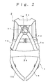
- the mounting body 1 includes a pair of shoulder part belts 1a which intersect on a back of the body of a user and are hung on both shoulders, a pair of thigh part belts 1b into which both thigh parts of the body of the user are inserted respectively, a waist part belt 1c mounted on a waist part of the body of the user and a chest part belt 1d positioned in front of a chest part of the body of the user.
- a connection ring 1e connectable to a rope not illustrated in the drawing is attached to an intersecting part of the shoulder part belts 1a.
- One ends of the shoulder part belts 1a are connected to side parts of the waist part belt 1c, respectively. The other ends thereof intersect in the back side and are respectively connected to the side parts of the waist part belt 1c.
- a back buckle 1f is attached to the intersecting part of the shoulder part belts 1a.
- the thigh part belts 1b are formed annular and top parts thereof are connected to the side parts of the waist part belt 1c, respectively.
- the waist part belt 1c includes a front buckle 1g with a known structure which can detachably combine both ends of the waist part belt in the front.
- a switch 1h put ON and OFF in conjunction with combination and cancel of combination of the front buckle 1g is provided inside the front buckle 1g.
- the chest part belt 1d is arranged upward from the waist part belt 1c and both ends thereof are connected to front sides of the shoulder part belts 1a, respectively.
- the air bag 2 is made of highly air-tight and durable fabric such as Vectran (wholly aromatic polyester), for example. Fabric made of that material is sewn or heat-sealed to form the shape of an air bag. That is, the air bag 2 includes a first air bag part 2a formed so as to extend toward the front from a back head part of the body of the user via the both shoulders and a second air bag part 2b formed so as to cover a back side of the waist part of the body of the user. The second air bag parts 2a and 2b communicate to each other via a communication part 2c extending over a side part of the second air bag part 2b from one end of the first air bag part 2a.
- Vectran whole aromatic polyester
- the air bag 2 is formed so that a part corresponding with the back of the body of the user in the first air bag part 2a is positioned upward from the connection ring 1e and a part corresponding with the back of the body of the user in the second air bag part 2b is positioned downward from the connection ring 1e.
- the gas filling apparatus 3 with a known configuration discharges compressed fluid encapsulated in a cylinder, for example, by explosion of gun powder and is connected to the communication part 2c of the air bag 2.
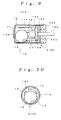
- Each drop sensor 4 includes a cylindrically formed container 10, a fixed contact point 11 provided on an inner circumferential plane of the container 10, a plurality of movable contact points 12 being elastic and deformable and arranged to be spaced apart from one another in the circumferential direction inside the container 10, and an inertia body 13 elastically deforming the movable contact points 12 to come into contact with the fixed contact point 11.
- the container 10 is made of a cylindrical electroconductive metal member provided with a bottom. An opening in one end thereof is sealed with an electroconductive lid plate 10a. In addition, a rod-like electroconductive terminal 10b is attached to the lid plate 10a so as to pierce the container 10 through to the interior through an insulating member 10c.
- the fixed contact point 11 is formed by the inner circumferential plane of the container 10.
- a plurality of protruding parts 11a formed by partially protruding inside the container 10 are provided on its circumferential plane, being spaced apart from one another in the circumferential direction so as to extend in an axial center direction of the container 10.
- the movable contact points 12 are made of electroconductive metal film plates extending in the axial center direction of the container 10 and are arranged to be spaced apart from one another in the circumferential direction of the container 10. One end side of each movable contact point 12 is sandwiched and fixed between an electroconductive metal plate 12a welded and fixed to an end plane of the electroconductive terminal 10b and an insulating member 12b made of synthetic resin arranged on the side of the lid plate 10a and is electrically conductive to the electroconductive terminal 10b.
- the inertia body 13 is a metal spherical body housed inside the container 10 and is arranged inside and surrounded by the movable contact points 12 in a freely movable manner.
- each drop sensor 4 in such a state of being influenced by gravity in a direction perpendicular to the axial center of the container 10 (in a radial direction of the container 10), the movable contact points 12 downward from the inertia body 13 are elastically deformed by the weight of the inertia body 13 and pressed to the fixed contact point 11 so as to be electrically conductive to the fixed contact point 11.
- apparent weight of the inertia body 13 is reduced.
- the movable contact points 12 bent toward the fixed contact point 11 by the inertia body 13 pushes the inertia body 13 back toward the center of the container 10 and depart from the fixed contact point 11 to cancel the conductive state to the fixed contact point 11. That is, the drop sensors 4 configure always-ON sensors.
- a plate-like insulating member 10d made of synthetic resin is attached to the bottom plane of the other end of the container 10.
- the insulating member 10d does not allow the movable contact points 12 to be electrically conductive to the fixed contact point 11 through the inertia body 13.
- the movable contact points 12 are respectively arranged between the protruding parts 11a of the fixed contact point 11.
- the contact between the inertia body 13 and the protruding parts 11a forms no gap so that the movable contact points 12 are not directly nipped between the inertia body 13 and the fixed contact point 11.
- the movable contact points 12 can be prevented from deformation due to the spread.
- the insulating member 12b on the side of the lid plate 10a is provided with a plurality of protrusions 12c protruding toward the bottom plane side of the container 10 which are arranged to be spaced apart from one another in the circumferential direction.
- the inertia body 13 moves to one end sides of the movable contact points 12, the inertia body 13 does not directly contact the one end sides of the movable contact points 12 by abutment of the inertia body 13 and the protrusions 12c.
- an enormous amount of stress generated by pressure of the inertia body 13 does not occur in the one end sides of the movable contact points 12, and plastic deformation and changes in property in the movable contact points 12 can be prevented.
- the acceleration sensor 5 is shaped the same as the drop sensors 4. Therefore, like reference characters will designate the same components as the drop sensors 4.
- the movable contact points 12 of a drop sensor 4 are formed so as to contact the fixed contact point 11 due to the weight of the inertia body 13
- the movable contact points 12 of the acceleration sensor 5 are higher than the movable contact points 12 of the drop sensor 4 in restoration nature and do not contact the fixed contact point 11 only with the weight of the inertia body 13. That is, the movable contact points 12 of the acceleration sensor 5 contact the fixed contact point 11 in the case where apparent gravity applied to the inertia body 13 gets larger than a predetermined amount (1.5 G, for example) accelerated in the direction of gravity. Thereby, the drop sensors 4 configure always-OFF sensors.
- the controller 6 is configured by a microcomputer and is connected to the switch 1h, the gas filling apparatus 3, each drop sensor 4 and the acceleration sensor 5. In addition, the controller 6 has a timer function.
- each drop sensor 4 and the acceleration sensor 5 are attached to a substrate 7a inside a center unit 7 as illustrated in Figure 4.
- the center unit 7 is housed in a housing part 1i on the side of a front plane provided in the torso part belt 1a of the mounting body 1 together with the controller 6.
- the drop sensors 4 are arranged on the same approximately vertical plane (on the substrate 7a) so that the axial centers of containers 10 make a predetermined inclination angle one another.
- the axial center of the container 10 is required to be present inside a predetermined angle range to the horizontal plane.
- the axial center of the container 10 is inclined within a predetermined angle range, the inertia body 13 contacts the bottom plane and the like of the container 10 so that its own weight will not be applied enough in the direction of bending the movable contact points 12.
- each drop sensor 4 is arranged to form a radial shape with the angles being changed within a predetermined inclination angle so that the ranges which do not give rise to the state as described above overlap each other. In that case, the drop sensors 4 have a uniform property in the circumference direction of the container 10.
- the substrate 7a of the center unit 7 is inclined along the approximately vertical flat plane but also in the case where the substrate 7a of the center unit 7 is inclined obliquely off the vertical plane, at least one drop sensor 4 will be put ON. In addition, when the center unit 7 enters a drop state, all the drop sensors 4 will be put OFF.
- the acceleration sensor 5 is arranged so that the axial center of the container 10 is approximately horizontal. That is, the acceleration sensor 5 detects upward acceleration in such a case where the user jumps or jumps over a slight step, and does not have to detect occurrence of acceleration in the directions other than the upward acceleration.
- the acceleration sensor 5 does not necessarily have to be one. Therefore two or more acceleration sensors 5 can be provided or a part thereof can be caused to incline slightly.
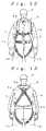
- the harness type safety belt configured as described above is used by a user A wearing the mounting body 1 on the body as illustrated in Figure 12 and Figure 13. That is, the user inserts both of the thigh parts into the respective thigh part belts 1c, hangs the shoulder part belts 1a onto the both shoulders and combines the front buckle 1f with the waist part belt 1b. Thereby the mounting body 1 is mounted on the body of the user.
- a rope not illustrated in the drawing is connected to the connection ring 1e. By connecting a hook of the rope to a life line of the work site, the user is suspended by the rope when the user accidentally falls.
- the body of the user is supported by not only the waist part belt 1b but also the shoulder part belts 1a and the thigh part belts 1c. Therefore a tension applied from the rope to the body of the user can be dispersed to each of the belts 1a, 1b and 1c and the body of the user is stably supported.
- the mounting body 1 is mounted on a user.
- the switch 1h of the mounting body 1 is put ON (S1)
- the following program will start. That is, in the case where no upward acceleration is taking place on the user A and the acceleration sensor 5 is not put ON (S2), the user A accidentally falls from an elevated work site, for example and that falling state puts OFF all the drop sensors 4 (S3).
- the OFF state of each drop sensor 4 continues for not less than a predetermined time period T1 (for example, 0.4 seconds) (S4).
- the gas filling apparatus 3 is activated (S5).
- the air bag 2 is inflated.
- the air bag parts 2a and 2b of the air bag 2 absorb a dropping impact to the user A.
- the air bag 2 provided in the mounting body 1 is inflated. Therefore, the air bag 2 can absorb a dropping shock and the dropping impact applied to the user A can be reduced.
- the user A is suspended by the rope.
- the body of the user A is supported by not only the waist part belt 1b but also the shoulder part belts 1a and the thigh part belts 1c. Therefore a tension applied from the rope to the body of the user can be dispersed to each of the belts 1a, 1b and 1c and the body of the user can be stably supported.
- the air bag 2 is formed by the first air bag part 2a with a part corresponding with the back of the body of the user being positioned upward from the connection ring 1e and the second air bag part 2b with a part corresponding with the back of the body of the user being positioned downward from the connection ring 1e. Therefore, there is no mutual interference between the air bag parts 2a and 2b and the connection ring 1e, and the rope can be always connectable to the connection ring 1e without any trouble.
- the first air bag part 2a is formed so as to extend toward the front from the back head part of the body of the user via the both shoulders and the second air bag part 2b is formed so as to cover the waist part of the body of the user.
- the air bag 2 can absorb at least a dropping shock to the back head part and the waist part of the body of the user and can effectively absorb the shock to the body of the user.
- the harness type safety belt includes the plurality of drop sensors 4 which are switched from an ON state to an OFF state when the apparent gravity taking place in the inertia body 13 decreases; and the acceleration sensor 5 which is switched from an OFF state to an ON state when the apparent gravity taking place in the inertia body 13 increases. Except the time period up to the elapse of the predetermined time period T2 after the acceleration sensor 5 is put ON by acceleration due to up and down movements other than a fall in such a case that the user jumps or jumps over a step, such a state that all the drop sensors 4 are detected being in the OFF states due to a fall of the user continues for not less than the predetermined time period T1. Then the air bag 2 is inflated. Thereby, malfunctions other than an occasion of a fall can be firmly prevented and improvement in reliability can be attained.
- each drop sensor 4 and the acceleration sensor 5 are provided in the positions corresponding with the waist part of the body of the user. Relatively sudden movements are less likely to occur in the vicinity of the waist part in the body of the user. Therefore, malfunctions of each drop sensor 4 and the acceleration sensor 5 can be reduced further.
- the harness type safety belt includes the front buckle 1g for detachably combining with the torso part belt 1a of the mounting body 1 in front of the body of the user and the switch 1h for bringing the controller 6 into an operable state when the front buckle 1g is combined. Therefore, mounting of the mounting body 1 concurrently enables the controller 6 to enter an operable state. Thereby unintentional default in operation can be firmly prevented.
Landscapes
- Health & Medical Sciences (AREA)
- General Health & Medical Sciences (AREA)
- Business, Economics & Management (AREA)
- Emergency Management (AREA)
- Emergency Lowering Means (AREA)
Abstract
The present invention provides a harness type safety belt capable of absorbing a dropping shock to a user even if the user accidentally falls from an elevated position. According to the present invention, in such a case that a user A fails to apply a hook of a rope to a life line and the user A falls from an elevated position, an air bag 2 provided in a mounting body 1 is inflated. Therefore, the air bag 2 can absorb a dropping shock and the dropping impact applied to the user A can be reduced. In addition, in the case where the user A falls with the hook of the rope being connected to the life line, the user A is suspended by the rope. The body of the user A is supported by not only a waist part belt 1b but also shoulder part belts 1a and thigh part belts 1c. Therefore a tension applied from the rope to the body of the user can be dispersed to each of the belts 1a, 1b and 1c and the body of the user can be stably supported.
Description
- The present invention relates to a harness type safety belt mainly used in an elevated work place such as a construction site.
- In general, for the work in an elevated position such as a construction site, workers are obligated to wear a safety belt for preventing a fall. That type of safety belt includes a torso belt mounted in a torso part of the body of a user and a rope with predetermined length connected to the torso belt. A holding hook attached to the tip of the rope is generally applied to a main rope and the like at the working site.
- However, the above described safety belt is mounted in the torso part of the body of the user. Therefore, a tension applied from the rope is concentrated in the torso part and the posture being suspended is apt to get unstable. Therefore, a so-called harness type safety belt (see
Patent Document 1, for example) is known. That belt includes belts extending over not only the torso part of the body of the user but also both shoulders, a back and thigh parts of the user. By connecting a rope to the belt of the back, a tension applied from the rope to the body of the user is dispersed to the belts so as to stably support the body of the user. - In addition, even if the above described safety belt is used, safety measures was not perfect because an accidental fall occasionally takes place in such a case that the user fails to apply the hook of the safety belt to a main rope and the like or at an occasion of applying the hook to another place. Therefore, as a shock absorbing aid for absorbing a dropping impact at a fall, a dropping shock absorbing aid is known (see
Patent Document 2, for example). That dropping shock absorbing aid includes a mounting body mounted on the body of a user, an air bag provided in the mounting body so as to correspond with a predetermined site of the body of the user and inflating means for inflating the air bag, wherein detection of a fall of the body of the user inflates the air bag with the inflating means. - However, in the above described dropping shock absorbing aid, the mounting body including a plurality of air bags is formed in the shape of a jacket. Therefore, when a harness type safety belt is worn over the mounting body, the belts of the safety belt prevent the air bags from being inflated. In the case of wearing the mounting body over the harness type safety belt, a rope connecting part provided in the back of the safety belt is covered by the mounting body, resulting in that no rope can be connected thereto. Consequently, there gives rise to a problem that concurrent use of the dropping shock absorbing aid and the harness type safety belt is difficult.
- Patent Document 2:
Japanese Patent Publication 11-333013 - Patent Document 1:
Japanese Patent Publication 7-96049 - The present invention has been attained in view of the above described problems and an object thereof is to provide a harness type safety belt capable of absorbing a dropping shock to a user even if the user accidentally falls from an elevated position.
- In order to attain the object of the present invention, a harness type safety belt comprising a pair of shoulder part belts which intersect on a back of the body of a user and are hung on both shoulders; a pair of annular thigh part belts into which both thigh parts of the body of the user are inserted respectively; a waist part belt mounted on a waist part of the body of the user; and a connection part capable of connecting a rope to an intersecting part of the shoulder part belts comprises an air bag provided in a predetermined position of the belts; inflation means for inflating the air bag; fall detection means for detecting a fall of the body of the user; and control means for inflating the air bag when the fall detection means detects a fall of the body of the user. Thereby, in the case where the user accidentally falls from an elevated position, the air bag fitted to a mounting body is inflated. Thereby the air bag absorbs a dropping shock. In addition, in the case where the user is suspended by the rope connected to the connection part, the body of the user is supported by not only the waist part belt but also the shoulder part belts and the thigh part belts. Therefore a tension applied from the rope to the body of the user can be dispersed to each of the belts and the body of the user is stably supported.
- The harness type safety belt of the present invention can absorb a dropping shock with the air bag in the case where a user falls from an elevated position in such a case that the user fails to apply the hook of a rope to a life line. Therefore, the dropping impact applied to the user can be reduced. In addition, in the case where the user is suspended by the rope, the body of the user can be supported by not only the waist part belt of the mounting body but also the shoulder part belts and the thigh part belts. Therefore a tension applied from the rope to the body of the user can be dispersed to each of the belts and the body of the user can be stably supported.
-
- Figure 1 is a front view of a harness type safety belt illustrating an embodiment of the present invention;
- Figure 2 is a rear view of a harness type safety belt;
- Figure 3 is a front view illustrating an inflated state of an air bag;
- Figure 4 is a rear view illustrating an inflated state of the air bag;
- Figure 5 is a left side view illustrating an inflated state of the air bag;
- Figure 6 is a right side view illustrating an inflated state of the air bag;
- Figure 7 is a block diagram illustrating a control system;
- Figure 8 is a front view illustrating the interior of a sensor unit;
- Figure 9 is side section of a drop sensor and an acceleration sensor;
- Figure 10 is a section in the direction of A-A arrows in Figure 9;
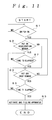
- Figure 11 is a flow chart illustrating operations of a controller;
- Figure 12 is a front view illustrating a contraction state of the air bag worn by a user;
- Figure 13 is a rear view illustrating a contraction state of the air bag worn by a user;
- Figure 14 is a front view illustrating an inflated state of the air bag worn by a user; and
- Figure 15 is a rear view illustrating an inflated state of the air bag worn by a user.
- 1 ... mounting body, 1a ... torso part belt, 1b ... shoulder part belt, 1c ... thigh part belt, 1e ... connection ring, 1g ... front buckle, 1h ... switch, 2 ... air bag, 2a ... first air bag body, 2b ... second air bag body, 3 ... gas filling apparatus, 4 ... drop sensor, 5 ... acceleration sensor and 6 ... controller.
- Figure 1 to Figure 15 illustrate an embodiment of the present invention.
- A harness type safety belt of the present embodiment is configured by a
mounting body 1 mounted on the body of a user; anair bag 2 provided in themounting body 1; agas filling apparatus 3 which inflates theair bag 2; a plurality ofdrop sensors 4 which detect dropping of the body of the user; anacceleration sensor 5 which detects an occurrence of upward and downward acceleration to the body of the user; and acontroller 6 which activates thegas filling apparatus 3 based on detection signals of each of thedrop sensors 4 and theacceleration sensor 5. Thedrop sensors 4 and theacceleration sensor 5 constitute fall detection means. - The
mounting body 1 includes a pair ofshoulder part belts 1a which intersect on a back of the body of a user and are hung on both shoulders, a pair of thigh part belts 1b into which both thigh parts of the body of the user are inserted respectively, a waist part belt 1c mounted on a waist part of the body of the user and a chest part belt 1d positioned in front of a chest part of the body of the user. A connection ring 1e connectable to a rope not illustrated in the drawing is attached to an intersecting part of theshoulder part belts 1a. One ends of theshoulder part belts 1a are connected to side parts of the waist part belt 1c, respectively. The other ends thereof intersect in the back side and are respectively connected to the side parts of the waist part belt 1c. In addition, a back buckle 1f is attached to the intersecting part of theshoulder part belts 1a. The thigh part belts 1b are formed annular and top parts thereof are connected to the side parts of the waist part belt 1c, respectively. The waist part belt 1c includes a front buckle 1g with a known structure which can detachably combine both ends of the waist part belt in the front. A switch 1h put ON and OFF in conjunction with combination and cancel of combination of the front buckle 1g is provided inside the front buckle 1g. The chest part belt 1d is arranged upward from the waist part belt 1c and both ends thereof are connected to front sides of theshoulder part belts 1a, respectively. - The
air bag 2 is made of highly air-tight and durable fabric such as Vectran (wholly aromatic polyester), for example. Fabric made of that material is sewn or heat-sealed to form the shape of an air bag. That is, theair bag 2 includes a first air bag part 2a formed so as to extend toward the front from a back head part of the body of the user via the both shoulders and a second air bag part 2b formed so as to cover a back side of the waist part of the body of the user. The second air bag parts 2a and 2b communicate to each other via a communication part 2c extending over a side part of the second air bag part 2b from one end of the first air bag part 2a. That is, theair bag 2 is formed so that a part corresponding with the back of the body of the user in the first air bag part 2a is positioned upward from the connection ring 1e and a part corresponding with the back of the body of the user in the second air bag part 2b is positioned downward from the connection ring 1e. - The
gas filling apparatus 3 with a known configuration discharges compressed fluid encapsulated in a cylinder, for example, by explosion of gun powder and is connected to the communication part 2c of theair bag 2. - Each
drop sensor 4 includes a cylindrically formedcontainer 10, a fixed contact point 11 provided on an inner circumferential plane of thecontainer 10, a plurality of movable contact points 12 being elastic and deformable and arranged to be spaced apart from one another in the circumferential direction inside thecontainer 10, and an inertia body 13 elastically deforming the movable contact points 12 to come into contact with the fixed contact point 11. - The
container 10 is made of a cylindrical electroconductive metal member provided with a bottom. An opening in one end thereof is sealed with an electroconductive lid plate 10a. In addition, a rod-like electroconductive terminal 10b is attached to the lid plate 10a so as to pierce thecontainer 10 through to the interior through an insulating member 10c. - The fixed contact point 11 is formed by the inner circumferential plane of the
container 10. A plurality of protruding parts 11a formed by partially protruding inside thecontainer 10 are provided on its circumferential plane, being spaced apart from one another in the circumferential direction so as to extend in an axial center direction of thecontainer 10. - The movable contact points 12 are made of electroconductive metal film plates extending in the axial center direction of the
container 10 and are arranged to be spaced apart from one another in the circumferential direction of thecontainer 10. One end side of eachmovable contact point 12 is sandwiched and fixed between an electroconductive metal plate 12a welded and fixed to an end plane of the electroconductive terminal 10b and an insulating member 12b made of synthetic resin arranged on the side of the lid plate 10a and is electrically conductive to the electroconductive terminal 10b. - The inertia body 13 is a metal spherical body housed inside the
container 10 and is arranged inside and surrounded by the movable contact points 12 in a freely movable manner. - In each
drop sensor 4, in such a state of being influenced by gravity in a direction perpendicular to the axial center of the container 10 (in a radial direction of the container 10), the movable contact points 12 downward from the inertia body 13 are elastically deformed by the weight of the inertia body 13 and pressed to the fixed contact point 11 so as to be electrically conductive to the fixed contact point 11. In addition, when eachdrop sensor 4 enters a drop state, apparent weight of the inertia body 13 is reduced. Therefore, the movable contact points 12 bent toward the fixed contact point 11 by the inertia body 13 pushes the inertia body 13 back toward the center of thecontainer 10 and depart from the fixed contact point 11 to cancel the conductive state to the fixed contact point 11. That is, thedrop sensors 4 configure always-ON sensors. - In addition, a plate-like insulating member 10d made of synthetic resin is attached to the bottom plane of the other end of the
container 10. In the case where the movable contact points 12 depart from the fixed contact point 11 so that the inertia body 13 contacts the bottom plane of thecontainer 10, the insulating member 10d does not allow the movable contact points 12 to be electrically conductive to the fixed contact point 11 through the inertia body 13. - The movable contact points 12 are respectively arranged between the protruding parts 11a of the fixed contact point 11. In the case where the inertia body 13 contacts the movable contact points 12, the contact between the inertia body 13 and the protruding parts 11a forms no gap so that the movable contact points 12 are not directly nipped between the inertia body 13 and the fixed contact point 11. Thereby, also in the case of spreading material that is apt to deform to form the movable contact points 12, the movable contact points 12 can be prevented from deformation due to the spread. In addition, the insulating member 12b on the side of the lid plate 10a is provided with a plurality of protrusions 12c protruding toward the bottom plane side of the
container 10 which are arranged to be spaced apart from one another in the circumferential direction. In the case where the inertia body 13 moves to one end sides of the movable contact points 12, the inertia body 13 does not directly contact the one end sides of the movable contact points 12 by abutment of the inertia body 13 and the protrusions 12c. Thereby, an enormous amount of stress generated by pressure of the inertia body 13 does not occur in the one end sides of the movable contact points 12, and plastic deformation and changes in property in the movable contact points 12 can be prevented. - The
acceleration sensor 5 is shaped the same as thedrop sensors 4. Therefore, like reference characters will designate the same components as thedrop sensors 4. In contrast to that the movable contact points 12 of adrop sensor 4 are formed so as to contact the fixed contact point 11 due to the weight of the inertia body 13, the movable contact points 12 of theacceleration sensor 5 are higher than the movable contact points 12 of thedrop sensor 4 in restoration nature and do not contact the fixed contact point 11 only with the weight of the inertia body 13. That is, the movable contact points 12 of theacceleration sensor 5 contact the fixed contact point 11 in the case where apparent gravity applied to the inertia body 13 gets larger than a predetermined amount (1.5 G, for example) accelerated in the direction of gravity. Thereby, thedrop sensors 4 configure always-OFF sensors. - The
controller 6 is configured by a microcomputer and is connected to the switch 1h, thegas filling apparatus 3, eachdrop sensor 4 and theacceleration sensor 5. In addition, thecontroller 6 has a timer function. - In addition, each
drop sensor 4 and theacceleration sensor 5 are attached to a substrate 7a inside acenter unit 7 as illustrated in Figure 4. Thecenter unit 7 is housed in a housing part 1i on the side of a front plane provided in thetorso part belt 1a of the mountingbody 1 together with thecontroller 6. - In that case, the
drop sensors 4 are arranged on the same approximately vertical plane (on the substrate 7a) so that the axial centers ofcontainers 10 make a predetermined inclination angle one another. In order that thedrop sensor 4 is in an ON state, that is, the movable contact points 12 are bent to contact the fixed contact point 11 due to the weight of the inertia body 13, the axial center of thecontainer 10 is required to be present inside a predetermined angle range to the horizontal plane. For example, the axial center of thecontainer 10 is inclined within a predetermined angle range, the inertia body 13 contacts the bottom plane and the like of thecontainer 10 so that its own weight will not be applied enough in the direction of bending the movable contact points 12. Therefore, a slight gravity change due to upward and downward movements cancels contacts between the movable contact points 12 and the fixed contact point 11 and much larger inclination will cancel contacts between the movable contact points 12 and the fixed contact point 11 regardless of the level of gravity. Therefore, eachdrop sensor 4 is arranged to form a radial shape with the angles being changed within a predetermined inclination angle so that the ranges which do not give rise to the state as described above overlap each other. In that case, thedrop sensors 4 have a uniform property in the circumference direction of thecontainer 10. Therefore, not only in the case where the substrate 7a of thecenter unit 7 is inclined along the approximately vertical flat plane but also in the case where the substrate 7a of thecenter unit 7 is inclined obliquely off the vertical plane, at least onedrop sensor 4 will be put ON. In addition, when thecenter unit 7 enters a drop state, all thedrop sensors 4 will be put OFF. - On the other hand, the
acceleration sensor 5 is arranged so that the axial center of thecontainer 10 is approximately horizontal. That is, theacceleration sensor 5 detects upward acceleration in such a case where the user jumps or jumps over a slight step, and does not have to detect occurrence of acceleration in the directions other than the upward acceleration. However, theacceleration sensor 5 does not necessarily have to be one. Therefore two ormore acceleration sensors 5 can be provided or a part thereof can be caused to incline slightly. - The harness type safety belt configured as described above is used by a user A wearing the mounting
body 1 on the body as illustrated in Figure 12 and Figure 13. That is, the user inserts both of the thigh parts into the respective thigh part belts 1c, hangs theshoulder part belts 1a onto the both shoulders and combines the front buckle 1f with the waist part belt 1b. Thereby the mountingbody 1 is mounted on the body of the user. In addition, a rope not illustrated in the drawing is connected to the connection ring 1e. By connecting a hook of the rope to a life line of the work site, the user is suspended by the rope when the user accidentally falls. At that occasion, the body of the user is supported by not only the waist part belt 1b but also theshoulder part belts 1a and the thigh part belts 1c. Therefore a tension applied from the rope to the body of the user can be dispersed to each of thebelts 1a, 1b and 1c and the body of the user is stably supported. - Next, operations of the above described safety belt will be described according to operations of the
controller 6 based on the flow chart in Figure 11. - At first, the mounting
body 1 is mounted on a user. When the switch 1h of the mountingbody 1 is put ON (S1), the following program will start. That is, in the case where no upward acceleration is taking place on the user A and theacceleration sensor 5 is not put ON (S2), the user A accidentally falls from an elevated work site, for example and that falling state puts OFF all the drop sensors 4 (S3). The OFF state of eachdrop sensor 4 continues for not less than a predetermined time period T1 (for example, 0.4 seconds) (S4). Then thegas filling apparatus 3 is activated (S5). Thereby, theair bag 2 is inflated. The air bag parts 2a and 2b of theair bag 2 absorb a dropping impact to the user A. - In addition, in the case the user A jumps or jumps over a slight step and the like, upward acceleration other than a fall takes place to put ON the acceleration sensor 5 (S2). Then after the elapse of not less than a predetermined time period T2 (for example, 0.4 seconds) (S6), ON and OFF of each
drop sensor 4 are determined (S3). For example, in the case where the user A jumps, even if thedrop sensors 4 are put OFF during jumping, the user normally lands at the point of time when the time period T2 elapsed. Then thedrop sensors 4 return to the ON state. Thedrop sensors 4 will not be determined to be OFF at step S3. Consequently thegas filling apparatus 3 will not be activated. In addition, the user A accidentally falls to put OFF thedrop sensors 4 and put ON the acceleration sensor 5 (S2). Then the OFF state of eachdrop sensor 4 continues even after the predetermined time period T2 (S6 and S3) elapsed. Therefore, after the predetermined time period T1 elapsed (S4), the gas filling apparatus is activated (S5). - Thus, in the harness type safety belt of the present embodiment, in such a case that the user A fails to apply the hook of the rope to the life line and the user A falls from an elevated position, the
air bag 2 provided in the mountingbody 1 is inflated. Therefore, theair bag 2 can absorb a dropping shock and the dropping impact applied to the user A can be reduced. In addition, in the case where the user A falls with the hook of the rope being connected to the life line, the user A is suspended by the rope. The body of the user A is supported by not only the waist part belt 1b but also theshoulder part belts 1a and the thigh part belts 1c. Therefore a tension applied from the rope to the body of the user can be dispersed to each of thebelts 1a, 1b and 1c and the body of the user can be stably supported. - In addition, the
air bag 2 is formed by the first air bag part 2a with a part corresponding with the back of the body of the user being positioned upward from the connection ring 1e and the second air bag part 2b with a part corresponding with the back of the body of the user being positioned downward from the connection ring 1e. Therefore, there is no mutual interference between the air bag parts 2a and 2b and the connection ring 1e, and the rope can be always connectable to the connection ring 1e without any trouble. - In that case, the first air bag part 2a is formed so as to extend toward the front from the back head part of the body of the user via the both shoulders and the second air bag part 2b is formed so as to cover the waist part of the body of the user. The
air bag 2 can absorb at least a dropping shock to the back head part and the waist part of the body of the user and can effectively absorb the shock to the body of the user. - In addition, the harness type safety belt includes the plurality of
drop sensors 4 which are switched from an ON state to an OFF state when the apparent gravity taking place in the inertia body 13 decreases; and theacceleration sensor 5 which is switched from an OFF state to an ON state when the apparent gravity taking place in the inertia body 13 increases. Except the time period up to the elapse of the predetermined time period T2 after theacceleration sensor 5 is put ON by acceleration due to up and down movements other than a fall in such a case that the user jumps or jumps over a step, such a state that all thedrop sensors 4 are detected being in the OFF states due to a fall of the user continues for not less than the predetermined time period T1. Then theair bag 2 is inflated. Thereby, malfunctions other than an occasion of a fall can be firmly prevented and improvement in reliability can be attained. - In that case, each
drop sensor 4 and theacceleration sensor 5 are provided in the positions corresponding with the waist part of the body of the user. Relatively sudden movements are less likely to occur in the vicinity of the waist part in the body of the user. Therefore, malfunctions of eachdrop sensor 4 and theacceleration sensor 5 can be reduced further. - In addition, the harness type safety belt includes the front buckle 1g for detachably combining with the
torso part belt 1a of the mountingbody 1 in front of the body of the user and the switch 1h for bringing thecontroller 6 into an operable state when the front buckle 1g is combined. Therefore, mounting of the mountingbody 1 concurrently enables thecontroller 6 to enter an operable state. Thereby unintentional default in operation can be firmly prevented.
Claims (7)
- A harness type safety belt comprising a pair of shoulder part belts which intersect on a back of the body of a user and are hung on both shoulders; a pair of annular thigh part belts into which both thigh parts of the body of the user are inserted respectively; a waist part belt mounted on a waist part of the body of the user; and a connection part capable of connecting a rope to an intersecting part of the shoulder part belts, comprising:an air bag provided in a predetermined position of the belts;inflation means for inflating the air bag;fall detection means for detecting a fall of the body of the user; andcontrol means for inflating the air bag when the fall detection means detects a fall of the body of the user.
- The harness type safety belt according to claim 1, wherein:the air bag is formed by a first air bag part with a part corresponding with the back of the body of the user being positioned upward from the connection part; and a second air bag part with a part corresponding with the back of the body of the user being positioned downward from the connection part.
- The harness type safety belt according to claim 2, wherein:the first air bag part is formed so as to extend toward the front from a back head part of the body of the user via the both shoulders; andthe second air bag part is formed so as to cover the waist part of the body of the user.
- The harness type safety belt according to claim 1, 2 or 3, wherein:the fall detection means is configured by at least one drop sensor which detects a dropping state of the body of the user; and at least one acceleration sensor which detects an occurrence of applying to the body of the user acceleration of not less than a predetermined level larger than acceleration due to gravity; andthe control means is configured to inflate the air bag when such a state that the dropping state is detected by the drop sensor continues for not less than a predetermined time period except a time period up to the elapse of the predetermined time period after the acceleration sensor detects an occurrence of acceleration of not less than the predetermined level.
- The harness type safety belt according to claim 4, wherein:each of the drop sensors is configured by a cylindrically formed container; a fixed contact point provided in an inner circumferential plane of the container; a plurality of movable contact points being elastic and deformable and arranged to be spaced apart from one another in a circumferential direction inside the container; and an inertia body elastically deforming, with its own weight, the movable contact points to come into contact with the fixed contact point, and drop sensors are arranged on the same approximately vertical plane so that axial centers of containers make a predetermined inclination angle one another;the acceleration sensor is configured by a cylindrically formed container; a fixed contact point provided in an inner circumferential plane of the container; a plurality of movable contact points being elastic and deformable and arranged to be spaced apart from one another in a circumferential direction inside the container; and an inertia body elastically deforming the movable contact points to come into contact with the fixed contact point at an occurrence of acceleration of not less than a predetermined level larger than acceleration due to gravity, and is arranged so that an axial center of the container is approximately parallel to a horizontal direction;the control means inflates the air bag when such a state that the movable contact points and the fixed contact points of all the drop sensors are detected being non-conductive continues for not less than a predetermined time period except a time period up to the elapse of the predetermined time period after the movable contact points and the fixed contact point of the acceleration sensor are detected being conductive.
- The harness type safety belt according to claim 4 or 5, wherein:each drop sensor and the acceleration sensor are provided in positions corresponding with the waist part of the body of the user.
- The harness type safety belt according to claim 1, 2, 3, 4, 5 or 6, further comprising:a combination member for detachably combining with a torso part belt in front of the body of the user; anda switch for bringing the control means into an operable state when the combination member is combined.
Applications Claiming Priority (1)
| Application Number | Priority Date | Filing Date | Title |
|---|---|---|---|
| PCT/JP2005/004366 WO2006095440A1 (en) | 2005-03-11 | 2005-03-11 | Harness type safety belt |
Publications (2)
| Publication Number | Publication Date |
|---|---|
| EP1857147A1 true EP1857147A1 (en) | 2007-11-21 |
| EP1857147A4 EP1857147A4 (en) | 2009-04-29 |
Family
ID=36953051
Family Applications (1)
| Application Number | Title | Priority Date | Filing Date |
|---|---|---|---|
| EP05720637A Ceased EP1857147A4 (en) | 2005-03-11 | 2005-03-11 | Harness type safety belt |
Country Status (4)
| Country | Link |
|---|---|
| US (1) | US7690051B2 (en) |
| EP (1) | EP1857147A4 (en) |
| CN (1) | CN101151070B (en) |
| WO (1) | WO2006095440A1 (en) |
Cited By (2)
| Publication number | Priority date | Publication date | Assignee | Title |
|---|---|---|---|---|
| FR2937254A1 (en) * | 2008-10-21 | 2010-04-23 | Sperian Fall Prot France | Antifall safety harness for supporting or retaining tower worker, has retaining belt attached on thigh of person carrying harness, and air cushion interposed between person and belt, where air cushion is inflated by inflating device |
| WO2011060061A1 (en) | 2009-11-11 | 2011-05-19 | Bell Helicopter Textron Inc. | Mobile energy attenuating seat and safety harness for aircraft |
Families Citing this family (25)
| Publication number | Priority date | Publication date | Assignee | Title |
|---|---|---|---|---|
| ITRM20070536A1 (en) * | 2007-10-10 | 2009-04-11 | Dainese Spa | PERSONAL PROTECTION DEVICE WITH INFLATABLE BAG AND INCORPORATING GARMENT OF THIS DEVICE. |
| KR101593046B1 (en) * | 2009-02-09 | 2016-02-11 | 가부시키가이샤 프롭프 | Airbag device for the body |
| US20110154561A1 (en) * | 2009-12-30 | 2011-06-30 | Tara Chand Singhal | Motorcycle rider safety harness |
| US8826469B2 (en) * | 2010-07-20 | 2014-09-09 | Joseph Tony London | Safety net harness |
| KR101093780B1 (en) * | 2011-02-23 | 2011-12-19 | 한국과학기술연구원 | Body Shock Relief |
| US8746739B2 (en) * | 2011-06-22 | 2014-06-10 | Carlston Life Support Systems, Inc. | Aircrew restraint system with integrated communications and controls |
| US20140047623A1 (en) * | 2012-08-15 | 2014-02-20 | S.S. Richards & Associates, LLC | Inflatable fall arrest and fall protection safety apparatus and method of use |
| CN102836507B (en) * | 2012-09-07 | 2014-08-20 | 高春青 | Automatic starting device for high-altitude landing |
| CN103041517A (en) * | 2013-01-24 | 2013-04-17 | 李艳香 | High-rise escape self-rescue lifter |
| US9622520B2 (en) | 2013-02-21 | 2017-04-18 | Andras Fenyves | Crash protection system |
| CN104096330A (en) * | 2013-04-15 | 2014-10-15 | 四川蓝讯宝迩电子科技有限公司 | Improved elastic safety belt |
| US20160183607A1 (en) * | 2014-02-11 | 2016-06-30 | Biosensor, LLC | Protective Clothing Article Including Fall Sensors and Deployable Air Bags |
| CN105233446A (en) * | 2015-10-21 | 2016-01-13 | 中国石油化工股份有限公司 | Multipurpose safety belt and use method thereof |
| US11810032B2 (en) | 2016-03-16 | 2023-11-07 | Triax Technologies, Inc. | Systems and methods for low-energy wireless applications using networked wearable sensors |
| US10692024B2 (en) | 2016-03-16 | 2020-06-23 | Triax Technologies, Inc. | Wireless mesh network system for monitoring worksite events including detecting false events |
| US11170616B2 (en) | 2016-03-16 | 2021-11-09 | Triax Technologies, Inc. | System and interfaces for managing workplace events |
| US10769562B2 (en) | 2016-03-16 | 2020-09-08 | Triax Technologies, Inc. | Sensor based system and method for authorizing operation of worksite equipment using a locally stored access control list |
| DE102016107144A1 (en) * | 2016-04-18 | 2017-10-19 | Bornack Gmbh & Co. Kg | Protection device for persons |
| CN106581885B (en) * | 2016-12-20 | 2019-04-12 | 新昌县勤勉贸易有限公司 | Electric power detects construction safety band hanger |
| CN106955099B (en) * | 2017-03-27 | 2023-06-09 | 遵义医学院附属医院 | A double-suction-cup type fixation for an electrocardiographic monitor |
| CN109529217B (en) * | 2018-11-22 | 2021-03-26 | 国网山东省电力公司莱西市供电公司 | A kind of omnidirectional safety belt and its use method |
| WO2020148655A1 (en) * | 2019-01-16 | 2020-07-23 | 3M Innovative Properties Company | Safety harness with removable rigid dorsal force-transfer member |
| WO2020191063A1 (en) | 2019-03-18 | 2020-09-24 | Fenyves Andras | Airbag system and related methods of inflating an airbag |
| US12471562B2 (en) * | 2022-09-08 | 2025-11-18 | Michael Ryan Remien | Pet safety apparatus |
| US12156506B2 (en) * | 2023-04-03 | 2024-12-03 | Ford Global Technologies, Llc | Inflatable harness assembly |
Family Cites Families (36)
| Publication number | Priority date | Publication date | Assignee | Title |
|---|---|---|---|---|
| US622555A (en) * | 1899-04-04 | Nut-lock | ||
| NO141299C (en) * | 1974-10-10 | 1980-02-06 | Siemens Ag | PACKING FOR HIGH-FREQUENCY CONNECTION OF RELIABLE METAL SHIELDING ELEMENTS |
| US4623752A (en) * | 1984-12-24 | 1986-11-18 | Burroughs Corporation | Double-action gasket assembly for EMI/RFI shielding |
| DE3901028A1 (en) * | 1989-01-14 | 1990-07-19 | Bayer Ag | NON-RESISTANT MOLDING AND CASTING MATERIALS AND WELDING ADDITIVES FOR BUILDING COMPONENTS ASSOCIATED WITH HOT, CONCENTRATED SWISS ACIDS |
| US5001297A (en) * | 1989-05-23 | 1991-03-19 | Instrument Specialties Company, Inc. | Track mounted electromagnetic shielding device |
| JP2605397B2 (en) | 1989-06-08 | 1997-04-30 | 富士電機株式会社 | Startup circuit for multi-output switching power supply |
| DE69125685T2 (en) * | 1990-11-05 | 1997-09-18 | Nippon Telegraph & Telephone | Protected communication device and system for protected transmission |
| JPH053928A (en) * | 1991-06-27 | 1993-01-14 | Mitsui Constr Co Ltd | Air bag built-in safety belt |
| US5209254A (en) * | 1991-10-29 | 1993-05-11 | Slomo Ancselovics | Water and sewerage system for construction, and protection for the same |
| US5204496A (en) * | 1992-04-01 | 1993-04-20 | Digital Equipment Corporation | EMI shielding gasket |
| US5329884A (en) * | 1992-06-04 | 1994-07-19 | Michael Bell | Harness with adjustable positioning pad and tool belt |
| JPH0796049A (en) | 1993-09-30 | 1995-04-11 | Hazama Gumi Ltd | Airbag system for a crash |
| US5534662A (en) * | 1994-08-31 | 1996-07-09 | International Business Machines Corporation | Chassis mounted electromagnetic interference grounding assembly for electronic modules |
| US5500952A (en) * | 1994-10-28 | 1996-03-26 | Keyes; Marshall J. | Hip inflatable protection device |
| JP3015269B2 (en) | 1994-12-05 | 2000-03-06 | 株式会社ワコム | Position detecting apparatus and method |
| US5523527A (en) * | 1994-12-22 | 1996-06-04 | International Business Machines Corporation | Sliding electromagnetic control contact device |
| JP3015269U (en) * | 1995-02-28 | 1995-08-29 | 伊三郎 黒岩 | Human body protection device |
| US5781936A (en) * | 1995-03-22 | 1998-07-21 | Alaloof; Jacob | Projection system for the rider of a non-enclosed vehicle and vehicle incorporating same |
| JPH11333013A (en) | 1998-05-27 | 1999-12-07 | Sankoo Kk | Harness lifeline |
| US6043991A (en) * | 1998-06-18 | 2000-03-28 | General Datacomm, Inc. | Card panel having a bracket with integrally formed track for an EMI reduction spring |
| US6225555B1 (en) * | 1998-07-15 | 2001-05-01 | Instrument Specialties Company, Inc. | Shielding strip |
| US6488024B2 (en) * | 1999-03-23 | 2002-12-03 | Mark Champion | Wood heater |
| US6320120B1 (en) * | 1999-04-15 | 2001-11-20 | Laird Technologies | Low profile clip-on shielding strip |
| US6444900B1 (en) * | 1999-05-19 | 2002-09-03 | Fci Americas Technology, Inc. | Electromagnetic interference shielding gasket |
| US6612157B2 (en) * | 2000-01-12 | 2003-09-02 | Ubukata Industries Co., Ltd. | Free fall sensor wherein normally closed circuit is opened in response to free fall conditions |
| CH694478A5 (en) * | 2000-01-20 | 2005-01-31 | Multi Holding Ag | Contact element. |
| US6403879B1 (en) * | 2000-06-21 | 2002-06-11 | Hewlett-Packard Company | Electronic chassis having an EMI gasket and integral ventilation holes |
| US6744301B1 (en) * | 2000-11-07 | 2004-06-01 | Intel Corporation | System using body-biased sleep transistors to reduce leakage power while minimizing performance penalties and noise |
| US6525266B2 (en) * | 2001-07-17 | 2003-02-25 | Enterasys Networks, Inc. | Circuit-board mounted clip for electromagnetic interference reduction |
| US20030116337A1 (en) * | 2001-12-20 | 2003-06-26 | Thompson Daniel T. | Captive low-profile EMI grounding clip |
| JP2003265638A (en) | 2002-03-14 | 2003-09-24 | Natl Inst Of Industrial Safety Independent Administrative Institution | Falling shock absorption auxiliary tool for human body |
| US6942630B2 (en) * | 2002-04-16 | 2005-09-13 | Biodex Medical Systems, Inc. | Inflatable suspension harness/body jacket |
| US6744641B2 (en) * | 2002-06-10 | 2004-06-01 | Sun Microsystems, Inc. | Electromagnetic interference gasket |
| US6859939B1 (en) * | 2002-10-21 | 2005-03-01 | Ralph J Osburn, Sr. | Inflatable restraint device |
| US6946598B1 (en) * | 2003-02-25 | 2005-09-20 | Storage Technology Corporation | Snap-in slot mount RFI/EMI clips |
| JP3769551B2 (en) | 2003-04-24 | 2006-04-26 | 藤井電工株式会社 | Harness type safety belt |
-
2005
- 2005-03-11 WO PCT/JP2005/004366 patent/WO2006095440A1/en not_active Ceased
- 2005-03-11 US US11/818,000 patent/US7690051B2/en not_active Expired - Fee Related
- 2005-03-11 EP EP05720637A patent/EP1857147A4/en not_active Ceased
- 2005-03-11 CN CN2005800489962A patent/CN101151070B/en not_active Expired - Fee Related
Non-Patent Citations (2)
| Title |
|---|
| No further relevant documents disclosed * |
| See also references of WO2006095440A1 * |
Cited By (4)
| Publication number | Priority date | Publication date | Assignee | Title |
|---|---|---|---|---|
| FR2937254A1 (en) * | 2008-10-21 | 2010-04-23 | Sperian Fall Prot France | Antifall safety harness for supporting or retaining tower worker, has retaining belt attached on thigh of person carrying harness, and air cushion interposed between person and belt, where air cushion is inflated by inflating device |
| WO2011060061A1 (en) | 2009-11-11 | 2011-05-19 | Bell Helicopter Textron Inc. | Mobile energy attenuating seat and safety harness for aircraft |
| EP2498647A4 (en) * | 2009-11-11 | 2013-08-28 | Bell Helicopter Textron Inc | ENERGY MITIGATION MOBILE SEAT AND SAFETY HARNESS FOR AN AIRCRAFT |
| US8991760B2 (en) | 2009-11-11 | 2015-03-31 | Textron Innovations Inc. | Mobile energy attenuating seat and safety harness for aircraft |
Also Published As
| Publication number | Publication date |
|---|---|
| WO2006095440A1 (en) | 2006-09-14 |
| US7690051B2 (en) | 2010-04-06 |
| EP1857147A4 (en) | 2009-04-29 |
| HK1118746A1 (en) | 2009-02-20 |
| US20090019623A1 (en) | 2009-01-22 |
| CN101151070B (en) | 2011-08-03 |
| CN101151070A (en) | 2008-03-26 |
Similar Documents
| Publication | Publication Date | Title |
|---|---|---|
| US7690051B2 (en) | Harness type safety belt | |
| CN102307627B (en) | Airbag device for human body | |
| US10709180B2 (en) | Protection system and method | |
| CN102039014B (en) | Safety belt and system for checking a usage status of the safety belt | |
| KR102148807B1 (en) | Human body protection apparatus, and system and method for controlling operation thereof | |
| JP4397660B2 (en) | Harness type safety belt | |
| CN211048465U (en) | Seat belts and safety gear | |
| US20170325521A1 (en) | Wearable airbag | |
| JP4621464B2 (en) | Airbag device for human body | |
| KR101341377B1 (en) | Protective clothing for crash detection | |
| KR20070115990A (en) | Harness type seat belt | |
| US11975677B2 (en) | Airbag device | |
| JP2003265638A (en) | Falling shock absorption auxiliary tool for human body | |
| US11950645B2 (en) | Wearable airbag device | |
| JP7026334B2 (en) | Airbag device for motorcycles | |
| ES3013291T3 (en) | Wearable protection device | |
| KR102317800B1 (en) | A Locking Type of an Indicating Apparatus for a Safety Cap and the Safety Cap with the Same | |
| HK1118746B (en) | Harness type safety belt | |
| JP3076334B1 (en) | Drop impact absorption aid for human body | |
| CN214229927U (en) | Air bag type anti-falling clothes for children | |
| JP2000051379A (en) | Shock absorbing auxiliary tool for human body | |
| JP2021194143A (en) | Air bag device for human body | |
| US12501949B2 (en) | Apparatus and method for protection of body areas upon impact | |
| WO2019035509A1 (en) | Safety device having inflator | |
| JP2023061790A (en) | Airbag device for human body |
Legal Events
| Date | Code | Title | Description |
|---|---|---|---|
| PUAI | Public reference made under article 153(3) epc to a published international application that has entered the european phase |
Free format text: ORIGINAL CODE: 0009012 |
|
| 17P | Request for examination filed |
Effective date: 20070921 |
|
| AK | Designated contracting states |
Kind code of ref document: A1 Designated state(s): AT BE BG CH CY CZ DE DK EE ES FI FR GB GR HU IE IS IT LI LT LU MC NL PL PT RO SE SI SK TR |
|
| DAX | Request for extension of the european patent (deleted) | ||
| A4 | Supplementary search report drawn up and despatched |
Effective date: 20090326 |
|
| 17Q | First examination report despatched |
Effective date: 20090814 |
|
| STAA | Information on the status of an ep patent application or granted ep patent |
Free format text: STATUS: THE APPLICATION HAS BEEN REFUSED |
|
| 18R | Application refused |
Effective date: 20100227 |