EP1855367B1 - Method and device for injecting reactive current during a mains supply voltage dip - Google Patents
Method and device for injecting reactive current during a mains supply voltage dip Download PDFInfo
- Publication number
- EP1855367B1 EP1855367B1 EP06725777.4A EP06725777A EP1855367B1 EP 1855367 B1 EP1855367 B1 EP 1855367B1 EP 06725777 A EP06725777 A EP 06725777A EP 1855367 B1 EP1855367 B1 EP 1855367B1
- Authority
- EP
- European Patent Office
- Prior art keywords
- network
- voltage
- phase
- voltage dip
- reactive power
- Prior art date
- Legal status (The legal status is an assumption and is not a legal conclusion. Google has not performed a legal analysis and makes no representation as to the accuracy of the status listed.)
- Expired - Lifetime
Links
Images

Classifications
-
- F—MECHANICAL ENGINEERING; LIGHTING; HEATING; WEAPONS; BLASTING
- F03—MACHINES OR ENGINES FOR LIQUIDS; WIND, SPRING, OR WEIGHT MOTORS; PRODUCING MECHANICAL POWER OR A REACTIVE PROPULSIVE THRUST, NOT OTHERWISE PROVIDED FOR
- F03D—WIND MOTORS
- F03D9/00—Adaptations of wind motors for special use; Combinations of wind motors with apparatus driven thereby; Wind motors specially adapted for installation in particular locations
-
- F—MECHANICAL ENGINEERING; LIGHTING; HEATING; WEAPONS; BLASTING
- F03—MACHINES OR ENGINES FOR LIQUIDS; WIND, SPRING, OR WEIGHT MOTORS; PRODUCING MECHANICAL POWER OR A REACTIVE PROPULSIVE THRUST, NOT OTHERWISE PROVIDED FOR
- F03D—WIND MOTORS
- F03D9/00—Adaptations of wind motors for special use; Combinations of wind motors with apparatus driven thereby; Wind motors specially adapted for installation in particular locations
- F03D9/20—Wind motors characterised by the driven apparatus
- F03D9/25—Wind motors characterised by the driven apparatus the apparatus being an electrical generator
- F03D9/255—Wind motors characterised by the driven apparatus the apparatus being an electrical generator connected to electrical distribution networks; Arrangements therefor
- F03D9/257—Wind motors characterised by the driven apparatus the apparatus being an electrical generator connected to electrical distribution networks; Arrangements therefor the wind motor being part of a wind farm
-
- H—ELECTRICITY
- H02—GENERATION; CONVERSION OR DISTRIBUTION OF ELECTRIC POWER
- H02J—ELECTRIC POWER NETWORKS; CIRCUIT ARRANGEMENTS OR SYSTEMS FOR SUPPLYING OR DISTRIBUTING ELECTRIC POWER; SYSTEMS FOR STORING ELECTRIC ENERGY
- H02J3/00—Circuit arrangements for AC mains or AC distribution networks
- H02J3/12—Arrangements for adjusting voltage in AC networks by changing a characteristic of the network load
- H02J3/16—Arrangements for adjusting voltage in AC networks by changing a characteristic of the network load by adjustment of reactive power
-
- H—ELECTRICITY
- H02—GENERATION; CONVERSION OR DISTRIBUTION OF ELECTRIC POWER
- H02J—ELECTRIC POWER NETWORKS; CIRCUIT ARRANGEMENTS OR SYSTEMS FOR SUPPLYING OR DISTRIBUTING ELECTRIC POWER; SYSTEMS FOR STORING ELECTRIC ENERGY
- H02J3/00—Circuit arrangements for AC mains or AC distribution networks
- H02J3/18—Arrangements for adjusting, eliminating or compensating reactive power in networks
-
- H—ELECTRICITY
- H02—GENERATION; CONVERSION OR DISTRIBUTION OF ELECTRIC POWER
- H02J—ELECTRIC POWER NETWORKS; CIRCUIT ARRANGEMENTS OR SYSTEMS FOR SUPPLYING OR DISTRIBUTING ELECTRIC POWER; SYSTEMS FOR STORING ELECTRIC ENERGY
- H02J3/00—Circuit arrangements for AC mains or AC distribution networks
- H02J3/18—Arrangements for adjusting, eliminating or compensating reactive power in networks
- H02J3/1821—Arrangements for adjusting, eliminating or compensating reactive power in networks using shunt compensators
- H02J3/1835—Arrangements for adjusting, eliminating or compensating reactive power in networks using shunt compensators with stepless control
- H02J3/1842—Arrangements for adjusting, eliminating or compensating reactive power in networks using shunt compensators with stepless control having reactive elements actively controlled by bridge converters, e.g. active filters or static compensators [STATCOM]
-
- Y—GENERAL TAGGING OF NEW TECHNOLOGICAL DEVELOPMENTS; GENERAL TAGGING OF CROSS-SECTIONAL TECHNOLOGIES SPANNING OVER SEVERAL SECTIONS OF THE IPC; TECHNICAL SUBJECTS COVERED BY FORMER USPC CROSS-REFERENCE ART COLLECTIONS [XRACs] AND DIGESTS
- Y02—TECHNOLOGIES OR APPLICATIONS FOR MITIGATION OR ADAPTATION AGAINST CLIMATE CHANGE
- Y02E—REDUCTION OF GREENHOUSE GAS [GHG] EMISSIONS, RELATED TO ENERGY GENERATION, TRANSMISSION OR DISTRIBUTION
- Y02E10/00—Energy generation through renewable energy sources
- Y02E10/70—Wind energy
- Y02E10/72—Wind turbines with rotation axis in wind direction
-
- Y—GENERAL TAGGING OF NEW TECHNOLOGICAL DEVELOPMENTS; GENERAL TAGGING OF CROSS-SECTIONAL TECHNOLOGIES SPANNING OVER SEVERAL SECTIONS OF THE IPC; TECHNICAL SUBJECTS COVERED BY FORMER USPC CROSS-REFERENCE ART COLLECTIONS [XRACs] AND DIGESTS
- Y02—TECHNOLOGIES OR APPLICATIONS FOR MITIGATION OR ADAPTATION AGAINST CLIMATE CHANGE
- Y02E—REDUCTION OF GREENHOUSE GAS [GHG] EMISSIONS, RELATED TO ENERGY GENERATION, TRANSMISSION OR DISTRIBUTION
- Y02E10/00—Energy generation through renewable energy sources
- Y02E10/70—Wind energy
- Y02E10/76—Power conversion electric or electronic aspects
-
- Y—GENERAL TAGGING OF NEW TECHNOLOGICAL DEVELOPMENTS; GENERAL TAGGING OF CROSS-SECTIONAL TECHNOLOGIES SPANNING OVER SEVERAL SECTIONS OF THE IPC; TECHNICAL SUBJECTS COVERED BY FORMER USPC CROSS-REFERENCE ART COLLECTIONS [XRACs] AND DIGESTS
- Y02—TECHNOLOGIES OR APPLICATIONS FOR MITIGATION OR ADAPTATION AGAINST CLIMATE CHANGE
- Y02E—REDUCTION OF GREENHOUSE GAS [GHG] EMISSIONS, RELATED TO ENERGY GENERATION, TRANSMISSION OR DISTRIBUTION
- Y02E40/00—Technologies for an efficient electrical power generation, transmission or distribution
- Y02E40/20—Active power filtering [APF]
-
- Y—GENERAL TAGGING OF NEW TECHNOLOGICAL DEVELOPMENTS; GENERAL TAGGING OF CROSS-SECTIONAL TECHNOLOGIES SPANNING OVER SEVERAL SECTIONS OF THE IPC; TECHNICAL SUBJECTS COVERED BY FORMER USPC CROSS-REFERENCE ART COLLECTIONS [XRACs] AND DIGESTS
- Y02—TECHNOLOGIES OR APPLICATIONS FOR MITIGATION OR ADAPTATION AGAINST CLIMATE CHANGE
- Y02E—REDUCTION OF GREENHOUSE GAS [GHG] EMISSIONS, RELATED TO ENERGY GENERATION, TRANSMISSION OR DISTRIBUTION
- Y02E40/00—Technologies for an efficient electrical power generation, transmission or distribution
- Y02E40/30—Reactive power compensation
Definitions
- This invention refers to a procedure and a device for injecting reactive power onto a network to which one or various electrical power generation machines are connected when a network voltage dip occurs, particularly for application at wind farms.
- a "voltage dip” may occur, which consists of a brusque decrease in voltage as a result of faults on the network, which causes a dip zone or constant decrease in voltage and a swell zone with increasing voltage once the fault which caused the dip is resolved, both of which have a determined duration depending on the voltage dip that occurred. Due to the technical requirements of the network, during the voltage dip a time variable injection of the reactive power required by the machines is needed, in order to contribute toward re-establishing the voltage and reducing the affects of said dip.
- the regulatory bodies for electrical networks define curves which determine the value of the reactive power that should be injected onto the network during the voltage dip. These curves give an reactive power value according to the depth of the detected dip.
- EP 1 122 856 A2 discloses a power system stabilization system with voltage and current detectors, which is able to calculate the required active and reactive powers for maintaining a predetermined voltage using a rechargeable battery as a power source.
- This invention is focused on providing a solution to this problem.
- the first aspect of this invention proposes a procedure for injecting reactive power onto a network to which one or various electrical power generation machines are connected when a voltage dip occurs, which comprises the following steps:
- the procedure allows the injection of the power required by the regulatory bodies on detecting the variation of the network voltage within very small time intervals and is able to vary the magnitude of the reactive power injected, also in within very small time frames.
- this invention proposes a device for carrying out the aforementioned procedure for a medium voltage network which integrates, as principal components, the following:
- the device according to the invention for a wind farm is comprised of in a preferred embodiment, the following elements:
- the device may be comprised of three-phase components when an injection per phase is not required, with its operation similar to that described below.
- a voltage dip occurs on the MV network 14, it is characterised by a zone of a brusque decrease in voltage, a dip zone of constant depth and a swell zone of increasing voltage once the fault causing the dip has been cleared.
- the regulatory bodies of the electrical networks define a curve ( Figure 2 ) on which the abscissa axis represents the voltage T at the point of connection to the network (in terms of its relation with the nominal voltage) and the ordinate axis represents the reactive power I (in terms of its relation with the total power).
- the date F1 indicates a normal operating situation and the date F2 indicates a voltage dip situation in which the curve C defines the magnitude of the reactive power that must be injected.
- the voltage dip detection circuit 10 preferably with DSP, using the appropriate algorithms and based on the values of the instantaneous voltage reading of the MV network 14, continuously calculates the peak and rms values of said voltages, and its phase, triggering the start-up process of the device according to this invention when it detects a voltage value below the threshold to which said device has been set.
- This circuit 10 is capable of detecting a dip in 1 millisecond, and can calculate the reactive component in amplitude and phase according to the relation defined in the C curve in 2 milliseconds, injecting reactive power some two milliseconds after the appearance of the dip on the network 14.
- the control circuit 20 calculates the reactive power to be injected based on the values of the instantaneous voltage measured on the network 14 by the circuit 10 based on the relation defined on curve C, along with the instantaneous active power that needs to be absorbed from the MV network, using the transformer 2 and the inverter 3, thus maintaining the voltage of the capacitor 4 connected on the dc side of the inverter 3.
- the control circuit 20 comprises a manoeuvre and control circuit for the different sections of the power stages, in order to control the switching on and off of each of them based on the reactive power value that needs to be injected sequentially at each instant.
Landscapes
- Engineering & Computer Science (AREA)
- Power Engineering (AREA)
- Life Sciences & Earth Sciences (AREA)
- Sustainable Development (AREA)
- Sustainable Energy (AREA)
- Chemical & Material Sciences (AREA)
- Combustion & Propulsion (AREA)
- Mechanical Engineering (AREA)
- General Engineering & Computer Science (AREA)
- Supply And Distribution Of Alternating Current (AREA)
- Control Of Electrical Variables (AREA)
Description
- This invention refers to a procedure and a device for injecting reactive power onto a network to which one or various electrical power generation machines are connected when a network voltage dip occurs, particularly for application at wind farms.
- On the electricity network connection at the output of a farm of electricity generating machines such as wind turbines, a "voltage dip" may occur, which consists of a brusque decrease in voltage as a result of faults on the network, which causes a dip zone or constant decrease in voltage and a swell zone with increasing voltage once the fault which caused the dip is resolved, both of which have a determined duration depending on the voltage dip that occurred. Due to the technical requirements of the network, during the voltage dip a time variable injection of the reactive power required by the machines is needed, in order to contribute toward re-establishing the voltage and reducing the affects of said dip.
- In this sense, the regulatory bodies for electrical networks define curves which determine the value of the reactive power that should be injected onto the network during the voltage dip. These curves give an reactive power value according to the depth of the detected dip.
- In this technique there are known devices with which reactive power is permanently injected at a variable setting which can be changed in time frames of minutes or seconds.
- With such devices however, the reactive power to be injected cannot be adapted to the variable network voltage in very short periods of time. In addition, the known devices are designed with overload capacities limited to two or three times their nominal capacities, which makes their application with high power economically impractical.
-
EP 1 122 856 A2 discloses a power system stabilization system with voltage and current detectors, which is able to calculate the required active and reactive powers for maintaining a predetermined voltage using a rechargeable battery as a power source. - This invention is focused on providing a solution to this problem.
- The first aspect of this invention proposes a procedure for injecting reactive power onto a network to which one or various electrical power generation machines are connected when a voltage dip occurs, which comprises the following steps:
- Permanent monitoring of the magnitude and phase of the network voltage.
- On detecting a mono-phase, two-phase or three-phase voltage dip, injecting reactive power on the phase or phases of the network in a variable manner for the time duration of the voltage dip in proportion to its magnitude, absorbing the active power necessary.
- The procedure allows the injection of the power required by the regulatory bodies on detecting the variation of the network voltage within very small time intervals and is able to vary the magnitude of the reactive power injected, also in within very small time frames.
- Secondly, this invention proposes a device for carrying out the aforementioned procedure for a medium voltage network which integrates, as principal components, the following:
- A medium voltage switch.
- A low voltage / medium voltage transformer (LV/MV).
- A dc/ac inverter.
- A capacitor for energy storage and device stability.
- A circuit for detecting voltage dips on the MV network;
- A control circuit for the group of above mentioned elements, which comprises a circuit for detecting the voltage dip on the MV network that, once it detects that the network voltage value is below the setting threshold, starts up the invention device in order for it to inject the instantaneous reactive power required to balance the network voltage according to the technical requirements indicated by the aforementioned curve and for the transitory duration of the voltage dip that has occurred
- Other characteristics and advantages of this invention become apparent in the detailed description and the accompanying figures that follow.
-
-
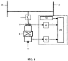
Figure 1 shows a block diagram with the components that make up a device according to this invention. -
Figure 2 shows a graph of the reactive power that must be injected onto the network during the transitory duration of the voltage dip. - The device according to the invention for a wind farm is comprised of in a preferred embodiment, the following elements:
- f) A medium voltage switch 1 for the connection of the device to the medium voltage circuit, from the
output 16 of the farm to thenetwork connection 14; - g) A LV/
MV transformer 2 connected on its LV side to a dc/ac inverter 3 and, on its MV side to the switch 1 for each phase; - h) A dc/
ac inverter 3, preferably with Insulated Gate Bipolar Transistor (IGBT) or Insulated Gate Commutated Thyristor (IGCT), for each phase, connected on its dc side to acapacitor 4, and on its ac side to the low voltage (LV) primary of thetransformer 2; - i) A
dc capacitor 4 connected to the power circuit of theinverter 3 on its dc side; - j) A
control circuit 20 for the group of aforementioned units, connected to thecontrols - a MV voltage sensor, or voltage transformer;
- a LV power sensor, hall effect transformer or similar;
- a dc voltage sensor, voltage transformer or hall effect transformer or similar;
- a voltage
dip detection circuit 10 with a digital signal processor (DSP), which detects the voltage value below the setting threshold of the device according to this invention;- a device for calculating the instantaneous reactive power to be injected, DSP or microprocessor;
- a device for calculating the instantaneous active power to be absorbed;
- a hysterisis band generator for the instantaneous reactive power to be injected;
- a comparison circuit for the actual power circuit readings with those preset by the bands;
- a circuit for generating on and off pulses for the auto-switching power semiconductors;
- a fibre optics coupling circuit between the described circuit and the trigger circuits of the semiconductors;
- a control and manoeuvre circuit for the different power stages.
- Instead of the aforementioned mono-phase components, the device may be comprised of three-phase components when an injection per phase is not required, with its operation similar to that described below.
- When a voltage dip occurs on the
MV network 14, it is characterised by a zone of a brusque decrease in voltage, a dip zone of constant depth and a swell zone of increasing voltage once the fault causing the dip has been cleared. - To remedy the effects of said dip on the network, the regulatory bodies of the electrical networks define a curve (
Figure 2 ) on which the abscissa axis represents the voltage T at the point of connection to the network (in terms of its relation with the nominal voltage) and the ordinate axis represents the reactive power I (in terms of its relation with the total power). The date F1 indicates a normal operating situation and the date F2 indicates a voltage dip situation in which the curve C defines the magnitude of the reactive power that must be injected. - The voltage
dip detection circuit 10, preferably with DSP, using the appropriate algorithms and based on the values of the instantaneous voltage reading of theMV network 14, continuously calculates the peak and rms values of said voltages, and its phase, triggering the start-up process of the device according to this invention when it detects a voltage value below the threshold to which said device has been set. Thiscircuit 10 is capable of detecting a dip in 1 millisecond, and can calculate the reactive component in amplitude and phase according to the relation defined in the C curve in 2 milliseconds, injecting reactive power some two milliseconds after the appearance of the dip on thenetwork 14. - Once the dip is detected, the
control circuit 20 calculates the reactive power to be injected based on the values of the instantaneous voltage measured on thenetwork 14 by thecircuit 10 based on the relation defined on curve C, along with the instantaneous active power that needs to be absorbed from the MV network, using thetransformer 2 and theinverter 3, thus maintaining the voltage of thecapacitor 4 connected on the dc side of theinverter 3. In addition, thecontrol circuit 20 comprises a manoeuvre and control circuit for the different sections of the power stages, in order to control the switching on and off of each of them based on the reactive power value that needs to be injected sequentially at each instant. - Other important characteristics of the device according to this invention, are as follows:
- The instantaneous power handled during the duration of the voltage dip by the device of this invention is between 20 to 30 MW, 30 times more than the admissible power of devices with standard auto-switching elements.
- The device needs no power source or ac/dc rectifier to function because it takes its power from the ac network and transfers it in a controlled manner to the capacitor connected on dc.
- The device is capable of extracting the necessary active power from the network in order to carry out its function even when network voltages falls to 20% of its nominal value, in other words when the depth of the voltage dip reaches 80%.
- The device is able to inject variable reactive power on each phase, and therefore acts correctly in the event of mono-phase or two-phase faults.
- The device is modular on each phase, therefore, in the event of a fault on one module, the remaining modules continue to operate.
- The device has a sequential control, therefore only the correct number of modules will function at each instant, based on the intensity that must be injected onto the network at any instant, in order to improve performance with low power and to reduce the injected harmonic distortion.
- In the embodiment we have just described, modifications can be made within the range defined in the following claims:
Claims (8)
- A device for injecting reactive power onto a medium voltage MV network (14) to which one or various electrical power generation machines are connected when a voltage dip occurs on said network (14) due to a mono-phase, two-phase or three-phase fault, comprising:a) a medium voltage switch (1) connectable to an output from a wind farm (16) to the MV network (14);b) an LV/MV transformer (2) connected on its MV side to the medium voltage switch (1) for each phase;c) a dc/ac inverter (3) on each phase with IGBT or IGCT semiconductors, connected on its AC side to the LV side of the LV/MV transformer;d) a dc capacitor (4) connected to a dc side of the dc/ac inverter (3); ande) a control circuit (20) for the group of the aforementioned units (1, 2, 3, 4), connected to the controls (10, 12, 13) associated with each of said units and which includes voltage and power sensors, a voltage dip detection circuit (10) with a digital signal processor DSP, devices for calculating the instantaneous voltage on the MV network (14) and voltage comparison circuits, so that when the voltage dip detection circuit (10) detects a voltage dip, the device is configured to inject reactive power onto the MV network (14) in a variable manner at each time interval, based on the measurements provided by the aforementioned sensors and circuits, and the device is further configured to take, during the voltage dip, the necessary active power from the MV network (14) to the capacitor (4).
- A device for injecting reactive power into a medium voltage MV network (14) to which one or various electrical power generation machines are connected when a voltage dip occurs on said MV network (14) due to a three-phase fault, comprising:a) a medium voltage switch (1) connectable to an output from a wind farm (16) to the MV network (14);b) an LV/MV three-phase transformer (2) connected on its MV side to the medium voltage switch (1) for each phase;c) a dc/ac three-phase inverter (3) with IGBT or IGCT semiconductors, connected on its AC side to the LV side of the LV/MV transformer;d) a dc capacitor (4) connected to a dc side of the dc/ac inverter (3); ande) a control circuit (20) for the group of the aforementioned units (1, 2, 3, 4), connected to the controls (10, 12, 13) associated with each of said units and which includes voltage and power sensors, a voltage dip detection circuit (10) with a digital signal processor DSP, devices for calculating the instantaneous voltage on the MV network (14) and voltage comparison circuits, so that when the voltage dip detection circuit (10) detects a voltage dip, the device is configured to inject reactive power onto the MV network (14) in a variable manner at each time interval, based on the measurements provided by the aforementioned sensors and circuits, and the device is further configured to take, during the voltage dip, the necessary active power from the MV network (14) to the capacitor (4).
- The device for injecting reactive power onto an MV network (14) according to claims 1 or 2, wherein the control circuit (20) is configured to vary the magnitude of the reactive power injected in time intervals of less than or equal to 20 milliseconds.
- The device for injecting reactive power onto an MV network (14) according to claims 1 or 2, wherein the device is configured to take its power from the MV network (14).
- The device for injecting reactive power onto an MV network (14) according to claims 1 or 2, wherein said machines are wind turbines.
- A procedure for injecting reactive power with a device according to claim 1 onto a MV network to which one or various electrical power generation machines are connected when a voltage dip occurs on said MV network due to a mono-phase, two-phase or three-phase fault, comprising1a) permanent monitoring of the magnitude and phase of the MV network voltage; andb) on detecting a mono-phase, two-phase or three-phase voltage dip, injecting reactive power, on the affected phase or phases of the MV network in proportion to the magnitude of the voltage dip, onto the MV network (14) in a variable manner for the duration of the voltage dip, and absorbing with said device, during the voltage dip, the necessary active power from the MV network (14).
- The procedure according to claim 6, wherein
the variation of the injected reactive power performed by the control circuit (20) takes place in time intervals of a less than or equal to 20 milliseconds. - The procedure according to claim 6, wherein said machines are wind turbines.
Applications Claiming Priority (2)
| Application Number | Priority Date | Filing Date | Title |
|---|---|---|---|
| ES200500411A ES2277724B1 (en) | 2005-02-23 | 2005-02-23 | PROCEDURE AND DEVICE FOR INJECTING REACTIVE INTENSITY DURING A NETWORK VOLTAGE HOLE. |
| PCT/ES2006/000079 WO2006089989A1 (en) | 2005-02-23 | 2006-02-22 | Method and device for injecting reactive current during a mains supply voltage dip |
Publications (4)
| Publication Number | Publication Date |
|---|---|
| EP1855367A1 EP1855367A1 (en) | 2007-11-14 |
| EP1855367A4 EP1855367A4 (en) | 2016-08-03 |
| EP1855367B1 true EP1855367B1 (en) | 2019-03-27 |
| EP1855367B8 EP1855367B8 (en) | 2019-05-22 |
Family
ID=36927056
Family Applications (1)
| Application Number | Title | Priority Date | Filing Date |
|---|---|---|---|
| EP06725777.4A Expired - Lifetime EP1855367B8 (en) | 2005-02-23 | 2006-02-22 | Method and device for injecting reactive current during a mains supply voltage dip |
Country Status (5)
| Country | Link |
|---|---|
| US (1) | US7821157B2 (en) |
| EP (1) | EP1855367B8 (en) |
| CN (1) | CN101142731B (en) |
| ES (2) | ES2277724B1 (en) |
| WO (1) | WO2006089989A1 (en) |
Families Citing this family (23)
| Publication number | Priority date | Publication date | Assignee | Title |
|---|---|---|---|---|
| EP2070175B1 (en) * | 2006-10-02 | 2016-12-07 | Vestas Wind Systems A/S | Method for operating a wind turbine connected to a utility grid during utility grid disturbance, wind turbine and wind park |
| CN101521385A (en) * | 2008-02-28 | 2009-09-02 | 西门子公司 | Dynamic voltage compensator for three-phase power supply system |
| WO2010060903A1 (en) * | 2008-11-28 | 2010-06-03 | Vestas Wind Systems A/S | A method and device for facilitating the localisation of a fault in a grid |
| WO2010066892A2 (en) * | 2008-12-12 | 2010-06-17 | Vestas Wind Systems A/S | Control method and apparatus |
| US8847562B2 (en) * | 2009-07-27 | 2014-09-30 | Gamesa Innovation & Technology, S.L. | Reactive power compensation in electrical power system |
| US10063059B2 (en) | 2009-10-27 | 2018-08-28 | Vestas Wind Systems A/S | Wind power plant with optimal power output |
| WO2012000517A2 (en) * | 2010-06-30 | 2012-01-05 | Vestas Wind Systems A/S | Operating a wind power plant including energy storage during grid faults |
| DE102010054233A1 (en) * | 2010-12-11 | 2012-06-14 | Adensis Gmbh | Power supply network with reactive power management |
| US8405247B2 (en) * | 2010-12-16 | 2013-03-26 | General Electric Company | Method and apparatus for control of fault-induced delayed voltage recovery (FIDVR) with photovoltaic and other inverter-based devices |
| DK2573895T3 (en) * | 2011-09-20 | 2014-03-10 | Siemens Ag | A method for operating a wind farm, the wind farm control unit and wind farm |
| US10103661B2 (en) | 2011-09-28 | 2018-10-16 | Vestas Wind Systems A/S | Wind power plant and a method for operating thereof |
| WO2014194914A1 (en) | 2013-06-03 | 2014-12-11 | Vestas Wind Systems A/S | Wind power plant controller |
| EP2851558B1 (en) * | 2013-09-18 | 2017-07-19 | Siemens Aktiengesellschaft | Method of controlling a wind turbine |
| US20160248246A1 (en) * | 2013-09-30 | 2016-08-25 | Vestas Wind Systems A/S | Detecting faults in electricity grids |
| DE102013222452A1 (en) * | 2013-11-05 | 2015-05-07 | Wobben Properties Gmbh | Method for operating a wind energy plant |
| JP6025769B2 (en) * | 2014-02-28 | 2016-11-16 | 三菱電機株式会社 | Elevator car power supply device |
| US9458830B2 (en) | 2014-09-05 | 2016-10-04 | General Electric Company | System and method for improving reactive current response time in a wind turbine |
| ES2624213B1 (en) * | 2016-01-12 | 2018-04-24 | José Luis MARTÍNEZ GONZÁLEZ | OPTIMIZED ELECTRIC TRANSFORMER |
| ES2764130T3 (en) * | 2016-02-03 | 2020-06-02 | Siemens Ag | Connection maintenance capacity in case of failure for wind turbine |
| DE102016105662A1 (en) | 2016-03-29 | 2017-10-05 | Wobben Properties Gmbh | Method for feeding electrical power into an electrical supply network with a wind farm and wind farm |
| DE102016106215A1 (en) | 2016-04-05 | 2017-10-05 | Wobben Properties Gmbh | Method and wind turbine for feeding electrical power |
| EP3900146A1 (en) | 2018-12-20 | 2021-10-27 | Vestas Wind Systems A/S | Boosting reactive current injection from wind turbine generators |
| CN113487071B (en) * | 2021-06-24 | 2022-03-04 | 四川大学 | SSTS and DVR coordinated action strategy making method and device for voltage sag management |
Family Cites Families (20)
| Publication number | Priority date | Publication date | Assignee | Title |
|---|---|---|---|---|
| AU646957B2 (en) * | 1991-07-01 | 1994-03-10 | Superconductivity, Inc. | Shunt connected superconducting energy stabilizing system |
| US5329222A (en) * | 1992-11-30 | 1994-07-12 | Westinghouse Electric Corporation | Apparatus and method for dynamic voltage restoration of utility distribution networks |
| DE19605419B4 (en) * | 1996-02-14 | 2005-08-04 | Rwe Rhein-Ruhr Aktiengesellschaft | Method for eliminating deviations of the actual voltage in a three-phase system from a predetermined setpoint voltage |
| JP2000041338A (en) * | 1998-05-18 | 2000-02-08 | Nissin Electric Co Ltd | Grid connection equipment |
| US6215202B1 (en) * | 1998-05-21 | 2001-04-10 | Bechtel Enterprises Inc. | Shunt connected superconducting energy management system having a single switchable connection to the grid |
| WO2000048286A1 (en) * | 1999-01-29 | 2000-08-17 | American Superconductor Corporation | Electric utility system with superconducting magnetic energy storage |
| US6134124A (en) * | 1999-05-12 | 2000-10-17 | Abb Power T&D Company Inc. | Universal distributed-resource interface |
| JP3352662B2 (en) * | 2000-02-03 | 2002-12-03 | 関西電力株式会社 | Power system stabilizing apparatus and power system stabilizing method using secondary battery system |
| JP2001327083A (en) * | 2000-05-18 | 2001-11-22 | Ngk Insulators Ltd | Power storage and compensation system by high- temperature secondary battery |
| CN1101070C (en) * | 2000-09-05 | 2003-02-05 | 上海交通大学 | Electric network reactive-load continuous compensation method and its compensation equipment |
| JP2003199252A (en) * | 2001-12-27 | 2003-07-11 | Kansai Electric Power Co Inc:The | Distributed power supply system and control method thereof |
| CN1359183A (en) * | 2002-01-11 | 2002-07-17 | 张玉良 | Mixing type reactive power generator |
| US7116010B2 (en) * | 2002-09-17 | 2006-10-03 | Wisconsin Alumni Research Foundation | Control of small distributed energy resources |
| CA2508728A1 (en) * | 2002-12-06 | 2004-06-24 | Electric Power Research Institute,Inc. | Uninterruptable power supply and generator system |
| US6858953B2 (en) * | 2002-12-20 | 2005-02-22 | Hawaiian Electric Company, Inc. | Power control interface between a wind farm and a power transmission system |
| US7099169B2 (en) * | 2003-02-21 | 2006-08-29 | Distributed Power, Inc. | DC to AC inverter with single-switch bipolar boost circuit |
| JP2004320859A (en) * | 2003-04-14 | 2004-11-11 | Hitachi Ltd | Reactive power compensator |
| US6924565B2 (en) * | 2003-08-18 | 2005-08-02 | General Electric Company | Continuous reactive power support for wind turbine generators |
| CN2659000Y (en) * | 2003-11-21 | 2004-11-24 | 华南理工大学 | Power transformer capable of dynamic reactive compensation |
| US7298059B2 (en) * | 2004-12-17 | 2007-11-20 | General Electric Company | System and method for operating a wind farm under high wind speed conditions |
-
2005
- 2005-02-23 ES ES200500411A patent/ES2277724B1/en not_active Expired - Fee Related
-
2006
- 2006-02-22 US US11/884,826 patent/US7821157B2/en active Active
- 2006-02-22 WO PCT/ES2006/000079 patent/WO2006089989A1/en not_active Ceased
- 2006-02-22 ES ES06725777T patent/ES2730573T3/en not_active Expired - Lifetime
- 2006-02-22 EP EP06725777.4A patent/EP1855367B8/en not_active Expired - Lifetime
- 2006-02-22 CN CN2006800053996A patent/CN101142731B/en not_active Expired - Fee Related
Non-Patent Citations (1)
| Title |
|---|
| None * |
Also Published As
| Publication number | Publication date |
|---|---|
| ES2730573T3 (en) | 2019-11-12 |
| ES2277724A1 (en) | 2007-07-16 |
| CN101142731B (en) | 2011-12-07 |
| US20080252143A1 (en) | 2008-10-16 |
| WO2006089989A1 (en) | 2006-08-31 |
| EP1855367B8 (en) | 2019-05-22 |
| ES2277724B1 (en) | 2008-06-16 |
| EP1855367A4 (en) | 2016-08-03 |
| CN101142731A (en) | 2008-03-12 |
| EP1855367A1 (en) | 2007-11-14 |
| US7821157B2 (en) | 2010-10-26 |
Similar Documents
| Publication | Publication Date | Title |
|---|---|---|
| US7821157B2 (en) | Method and device for injecting reactive current during a mains supply voltage dip | |
| US7906870B2 (en) | System and method for anti-islanding, such as anti-islanding for a grid-connected photovoltaic inverter | |
| US9170306B2 (en) | Islanding detection method and system | |
| US9520819B2 (en) | System and method for controlling a power generation system based on a detected islanding event | |
| US8097971B2 (en) | Wind turbine generator system | |
| US6219623B1 (en) | Anti-islanding method and apparatus for distributed power generation | |
| EP3314715B1 (en) | Controlled inrush current for converter-connected grid filter | |
| US20120300510A1 (en) | Method and apparatus for controlling a dc-transmission link | |
| CN102684219B (en) | Method and apparatus for detecting islanding conditions of distributed generator | |
| US7791223B2 (en) | Method and device for preventing the disconnection of an electric power generating plant from the electrical grid | |
| WO2015172959A1 (en) | Centralized dc curtailment for overvoltage protection | |
| WO2015043602A1 (en) | Detecting faults in electricity grids | |
| Shamseh et al. | Adaptive virtual impedance for reactive current control during fault conditions in grid-forming inverters | |
| EP3100291B1 (en) | Dc compensation for high dc current in transformer | |
| RU2734165C1 (en) | Method of recording isolated network formation | |
| Kuncoro et al. | DVR to voltage sag mitigation due to induction motor starting and 3 phase fault | |
| Dey | Comparison of DVR and D-STATCOM for voltage quality improvement | |
| KR101682561B1 (en) | Method and system for controlling low-voltage ride through of a wind farm | |
| Amarís | Power Quality Solutions for Voltage Dip compensation at wind farms | |
| Priya et al. | A Dynamic Voltage Restorer with Voltage Sag Compensation at Medium Voltage Level Using PI Control Scheme | |
| US20260039120A1 (en) | High voltage protection of electrolyzer in a wind power plant | |
| Li et al. | Impact of load transients on dynamic voltage restorers | |
| Aimun et al. | Power Quality Enhancement through Voltage Sag Mitigation using Dynamic Voltage Restorer in Distribution System | |
| Datta et al. | Active perturbation based islanding detection scheme for grid connected wind energy system | |
| Omar et al. | Design requirements for a dynamic series compensator for voltage sags mitigation in low voltage distribution system |
Legal Events
| Date | Code | Title | Description |
|---|---|---|---|
| PUAI | Public reference made under article 153(3) epc to a published international application that has entered the european phase |
Free format text: ORIGINAL CODE: 0009012 |
|
| 17P | Request for examination filed |
Effective date: 20070919 |
|
| AK | Designated contracting states |
Kind code of ref document: A1 Designated state(s): AT BE BG CH CY CZ DE DK EE ES FI FR GB GR HU IE IS IT LI LT LU LV MC NL PL PT RO SE SI SK TR |
|
| DAX | Request for extension of the european patent (deleted) | ||
| RAP1 | Party data changed (applicant data changed or rights of an application transferred) |
Owner name: GAMESA INNOVATION & TECHNOLOGY, S.L. |
|
| RA4 | Supplementary search report drawn up and despatched (corrected) |
Effective date: 20160704 |
|
| RIC1 | Information provided on ipc code assigned before grant |
Ipc: F03D 9/00 20160101ALI20160628BHEP Ipc: H02J 3/18 20060101AFI20160628BHEP Ipc: H02J 3/16 20060101ALI20160628BHEP |
|
| STAA | Information on the status of an ep patent application or granted ep patent |
Free format text: STATUS: EXAMINATION IS IN PROGRESS |
|
| 17Q | First examination report despatched |
Effective date: 20171108 |
|
| REG | Reference to a national code |
Ref country code: DE Ref legal event code: R079 Ref document number: 602006057671 Country of ref document: DE Free format text: PREVIOUS MAIN CLASS: H02J0003180000 Ipc: H02J0003160000 |
|
| RIC1 | Information provided on ipc code assigned before grant |
Ipc: H02J 3/18 20060101ALI20180919BHEP Ipc: H02J 3/16 20060101AFI20180919BHEP |
|
| GRAP | Despatch of communication of intention to grant a patent |
Free format text: ORIGINAL CODE: EPIDOSNIGR1 |
|
| STAA | Information on the status of an ep patent application or granted ep patent |
Free format text: STATUS: GRANT OF PATENT IS INTENDED |
|
| RIN1 | Information on inventor provided before grant (corrected) |
Inventor name: VISIERS GUIXOT, MANUEL Inventor name: LLORENTE GONZALEZ, JOSE IGNACIO |
|
| INTG | Intention to grant announced |
Effective date: 20181029 |
|
| GRAS | Grant fee paid |
Free format text: ORIGINAL CODE: EPIDOSNIGR3 |
|
| GRAA | (expected) grant |
Free format text: ORIGINAL CODE: 0009210 |
|
| STAA | Information on the status of an ep patent application or granted ep patent |
Free format text: STATUS: THE PATENT HAS BEEN GRANTED |
|
| AK | Designated contracting states |
Kind code of ref document: B1 Designated state(s): AT BE BG CH CY CZ DE DK EE ES FI FR GB GR HU IE IS IT LI LT LU LV MC NL PL PT RO SE SI SK TR |
|
| REG | Reference to a national code |
Ref country code: GB Ref legal event code: FG4D |
|
| REG | Reference to a national code |
Ref country code: CH Ref legal event code: EP |
|
| REG | Reference to a national code |
Ref country code: AT Ref legal event code: REF Ref document number: 1114176 Country of ref document: AT Kind code of ref document: T Effective date: 20190415 |
|
| RAP2 | Party data changed (patent owner data changed or rights of a patent transferred) |
Owner name: SIEMENS GAMESA RENEWABLE ENERGY INNOVATION & TECHN |
|
| REG | Reference to a national code |
Ref country code: IE Ref legal event code: FG4D |
|
| REG | Reference to a national code |
Ref country code: DE Ref legal event code: R096 Ref document number: 602006057671 Country of ref document: DE |
|
| REG | Reference to a national code |
Ref country code: DE Ref legal event code: R082 Ref document number: 602006057671 Country of ref document: DE Representative=s name: ASPACHER, KARL-GEORG, DE |
|
| REG | Reference to a national code |
Ref country code: CH Ref legal event code: PK Free format text: BERICHTIGUNG B8 |
|
| PG25 | Lapsed in a contracting state [announced via postgrant information from national office to epo] |
Ref country code: FI Free format text: LAPSE BECAUSE OF FAILURE TO SUBMIT A TRANSLATION OF THE DESCRIPTION OR TO PAY THE FEE WITHIN THE PRESCRIBED TIME-LIMIT Effective date: 20190327 Ref country code: LT Free format text: LAPSE BECAUSE OF FAILURE TO SUBMIT A TRANSLATION OF THE DESCRIPTION OR TO PAY THE FEE WITHIN THE PRESCRIBED TIME-LIMIT Effective date: 20190327 Ref country code: SE Free format text: LAPSE BECAUSE OF FAILURE TO SUBMIT A TRANSLATION OF THE DESCRIPTION OR TO PAY THE FEE WITHIN THE PRESCRIBED TIME-LIMIT Effective date: 20190327 |
|
| REG | Reference to a national code |
Ref country code: NL Ref legal event code: MP Effective date: 20190327 |
|
| PG25 | Lapsed in a contracting state [announced via postgrant information from national office to epo] |
Ref country code: LV Free format text: LAPSE BECAUSE OF FAILURE TO SUBMIT A TRANSLATION OF THE DESCRIPTION OR TO PAY THE FEE WITHIN THE PRESCRIBED TIME-LIMIT Effective date: 20190327 Ref country code: NL Free format text: LAPSE BECAUSE OF FAILURE TO SUBMIT A TRANSLATION OF THE DESCRIPTION OR TO PAY THE FEE WITHIN THE PRESCRIBED TIME-LIMIT Effective date: 20190327 Ref country code: BG Free format text: LAPSE BECAUSE OF FAILURE TO SUBMIT A TRANSLATION OF THE DESCRIPTION OR TO PAY THE FEE WITHIN THE PRESCRIBED TIME-LIMIT Effective date: 20190627 Ref country code: GR Free format text: LAPSE BECAUSE OF FAILURE TO SUBMIT A TRANSLATION OF THE DESCRIPTION OR TO PAY THE FEE WITHIN THE PRESCRIBED TIME-LIMIT Effective date: 20190628 |
|
| REG | Reference to a national code |
Ref country code: AT Ref legal event code: MK05 Ref document number: 1114176 Country of ref document: AT Kind code of ref document: T Effective date: 20190327 |
|
| PG25 | Lapsed in a contracting state [announced via postgrant information from national office to epo] |
Ref country code: PT Free format text: LAPSE BECAUSE OF FAILURE TO SUBMIT A TRANSLATION OF THE DESCRIPTION OR TO PAY THE FEE WITHIN THE PRESCRIBED TIME-LIMIT Effective date: 20190727 Ref country code: SK Free format text: LAPSE BECAUSE OF FAILURE TO SUBMIT A TRANSLATION OF THE DESCRIPTION OR TO PAY THE FEE WITHIN THE PRESCRIBED TIME-LIMIT Effective date: 20190327 Ref country code: CZ Free format text: LAPSE BECAUSE OF FAILURE TO SUBMIT A TRANSLATION OF THE DESCRIPTION OR TO PAY THE FEE WITHIN THE PRESCRIBED TIME-LIMIT Effective date: 20190327 Ref country code: RO Free format text: LAPSE BECAUSE OF FAILURE TO SUBMIT A TRANSLATION OF THE DESCRIPTION OR TO PAY THE FEE WITHIN THE PRESCRIBED TIME-LIMIT Effective date: 20190327 Ref country code: IT Free format text: LAPSE BECAUSE OF FAILURE TO SUBMIT A TRANSLATION OF THE DESCRIPTION OR TO PAY THE FEE WITHIN THE PRESCRIBED TIME-LIMIT Effective date: 20190327 Ref country code: EE Free format text: LAPSE BECAUSE OF FAILURE TO SUBMIT A TRANSLATION OF THE DESCRIPTION OR TO PAY THE FEE WITHIN THE PRESCRIBED TIME-LIMIT Effective date: 20190327 |
|
| REG | Reference to a national code |
Ref country code: ES Ref legal event code: FG2A Ref document number: 2730573 Country of ref document: ES Kind code of ref document: T3 Effective date: 20191112 |
|
| PG25 | Lapsed in a contracting state [announced via postgrant information from national office to epo] |
Ref country code: PL Free format text: LAPSE BECAUSE OF FAILURE TO SUBMIT A TRANSLATION OF THE DESCRIPTION OR TO PAY THE FEE WITHIN THE PRESCRIBED TIME-LIMIT Effective date: 20190327 |
|
| PG25 | Lapsed in a contracting state [announced via postgrant information from national office to epo] |
Ref country code: IS Free format text: LAPSE BECAUSE OF FAILURE TO SUBMIT A TRANSLATION OF THE DESCRIPTION OR TO PAY THE FEE WITHIN THE PRESCRIBED TIME-LIMIT Effective date: 20190727 Ref country code: AT Free format text: LAPSE BECAUSE OF FAILURE TO SUBMIT A TRANSLATION OF THE DESCRIPTION OR TO PAY THE FEE WITHIN THE PRESCRIBED TIME-LIMIT Effective date: 20190327 |
|
| REG | Reference to a national code |
Ref country code: DE Ref legal event code: R097 Ref document number: 602006057671 Country of ref document: DE |
|
| PG25 | Lapsed in a contracting state [announced via postgrant information from national office to epo] |
Ref country code: DK Free format text: LAPSE BECAUSE OF FAILURE TO SUBMIT A TRANSLATION OF THE DESCRIPTION OR TO PAY THE FEE WITHIN THE PRESCRIBED TIME-LIMIT Effective date: 20190327 |
|
| PLBE | No opposition filed within time limit |
Free format text: ORIGINAL CODE: 0009261 |
|
| STAA | Information on the status of an ep patent application or granted ep patent |
Free format text: STATUS: NO OPPOSITION FILED WITHIN TIME LIMIT |
|
| PG25 | Lapsed in a contracting state [announced via postgrant information from national office to epo] |
Ref country code: SI Free format text: LAPSE BECAUSE OF FAILURE TO SUBMIT A TRANSLATION OF THE DESCRIPTION OR TO PAY THE FEE WITHIN THE PRESCRIBED TIME-LIMIT Effective date: 20190327 |
|
| 26N | No opposition filed |
Effective date: 20200103 |
|
| PG25 | Lapsed in a contracting state [announced via postgrant information from national office to epo] |
Ref country code: TR Free format text: LAPSE BECAUSE OF FAILURE TO SUBMIT A TRANSLATION OF THE DESCRIPTION OR TO PAY THE FEE WITHIN THE PRESCRIBED TIME-LIMIT Effective date: 20190327 |
|
| REG | Reference to a national code |
Ref country code: CH Ref legal event code: PL |
|
| REG | Reference to a national code |
Ref country code: BE Ref legal event code: MM Effective date: 20200229 |
|
| PG25 | Lapsed in a contracting state [announced via postgrant information from national office to epo] |
Ref country code: MC Free format text: LAPSE BECAUSE OF FAILURE TO SUBMIT A TRANSLATION OF THE DESCRIPTION OR TO PAY THE FEE WITHIN THE PRESCRIBED TIME-LIMIT Effective date: 20190327 Ref country code: LU Free format text: LAPSE BECAUSE OF NON-PAYMENT OF DUE FEES Effective date: 20200222 |
|
| PG25 | Lapsed in a contracting state [announced via postgrant information from national office to epo] |
Ref country code: LI Free format text: LAPSE BECAUSE OF NON-PAYMENT OF DUE FEES Effective date: 20200229 Ref country code: CH Free format text: LAPSE BECAUSE OF NON-PAYMENT OF DUE FEES Effective date: 20200229 |
|
| PG25 | Lapsed in a contracting state [announced via postgrant information from national office to epo] |
Ref country code: IE Free format text: LAPSE BECAUSE OF NON-PAYMENT OF DUE FEES Effective date: 20200222 |
|
| PG25 | Lapsed in a contracting state [announced via postgrant information from national office to epo] |
Ref country code: BE Free format text: LAPSE BECAUSE OF NON-PAYMENT OF DUE FEES Effective date: 20200229 |
|
| PG25 | Lapsed in a contracting state [announced via postgrant information from national office to epo] |
Ref country code: CY Free format text: LAPSE BECAUSE OF FAILURE TO SUBMIT A TRANSLATION OF THE DESCRIPTION OR TO PAY THE FEE WITHIN THE PRESCRIBED TIME-LIMIT Effective date: 20190327 |
|
| REG | Reference to a national code |
Ref country code: DE Ref legal event code: R082 Ref document number: 602006057671 Country of ref document: DE Representative=s name: SAUTHOFF, KARSTEN, DIPL.-ING. UNIV., DE |
|
| PGFP | Annual fee paid to national office [announced via postgrant information from national office to epo] |
Ref country code: ES Payment date: 20240319 Year of fee payment: 19 |
|
| PGFP | Annual fee paid to national office [announced via postgrant information from national office to epo] |
Ref country code: DE Payment date: 20240216 Year of fee payment: 19 Ref country code: GB Payment date: 20240222 Year of fee payment: 19 |
|
| PGFP | Annual fee paid to national office [announced via postgrant information from national office to epo] |
Ref country code: FR Payment date: 20240221 Year of fee payment: 19 |
|
| REG | Reference to a national code |
Ref country code: DE Ref legal event code: R119 Ref document number: 602006057671 Country of ref document: DE |
|
| GBPC | Gb: european patent ceased through non-payment of renewal fee |
Effective date: 20250222 |
|
| PG25 | Lapsed in a contracting state [announced via postgrant information from national office to epo] |
Ref country code: DE Free format text: LAPSE BECAUSE OF NON-PAYMENT OF DUE FEES Effective date: 20250902 |
|
| PG25 | Lapsed in a contracting state [announced via postgrant information from national office to epo] |
Ref country code: GB Free format text: LAPSE BECAUSE OF NON-PAYMENT OF DUE FEES Effective date: 20250222 |
|
| PG25 | Lapsed in a contracting state [announced via postgrant information from national office to epo] |
Ref country code: FR Free format text: LAPSE BECAUSE OF NON-PAYMENT OF DUE FEES Effective date: 20250228 |
|
| REG | Reference to a national code |
Ref country code: ES Ref legal event code: FD2A Effective date: 20260406 |
|
| PG25 | Lapsed in a contracting state [announced via postgrant information from national office to epo] |
Ref country code: ES Free format text: LAPSE BECAUSE OF NON-PAYMENT OF DUE FEES Effective date: 20250223 |