EP1855257A1 - Electronic warning device - Google Patents
Electronic warning device Download PDFInfo
- Publication number
- EP1855257A1 EP1855257A1 EP07462005A EP07462005A EP1855257A1 EP 1855257 A1 EP1855257 A1 EP 1855257A1 EP 07462005 A EP07462005 A EP 07462005A EP 07462005 A EP07462005 A EP 07462005A EP 1855257 A1 EP1855257 A1 EP 1855257A1
- Authority
- EP
- European Patent Office
- Prior art keywords
- housing
- back panel
- cover
- arrow
- lighting units
- Prior art date
- Legal status (The legal status is an assumption and is not a legal conclusion. Google has not performed a legal analysis and makes no representation as to the accuracy of the status listed.)
- Withdrawn
Links
Images


Classifications
-
- G—PHYSICS
- G08—SIGNALLING
- G08B—SIGNALLING SYSTEMS, e.g. PERSONAL CALLING SYSTEMS; ORDER TELEGRAPHS; ALARM SYSTEMS
- G08B5/00—Visible signalling systems, e.g. visible personal calling systems or remote indication of seats occupied
- G08B5/22—Visible signalling systems, e.g. visible personal calling systems or remote indication of seats occupied using electric transmission; using electromagnetic transmission
- G08B5/36—Visible signalling systems, e.g. visible personal calling systems or remote indication of seats occupied using electric transmission; using electromagnetic transmission using visible light sources
- G08B5/38—Visible signalling systems, e.g. visible personal calling systems or remote indication of seats occupied using electric transmission; using electromagnetic transmission using visible light sources using flashing light
-
- G—PHYSICS
- G09—EDUCATION; CRYPTOGRAPHY; DISPLAY; ADVERTISING; SEALS
- G09F—DISPLAYING; ADVERTISING; SIGNS; LABELS OR NAME-PLATES; SEALS
- G09F19/00—Advertising or display means not otherwise provided for
- G09F19/22—Advertising or display means on roads, walls or similar surfaces, e.g. illuminated
-
- G—PHYSICS
- G08—SIGNALLING
- G08B—SIGNALLING SYSTEMS, e.g. PERSONAL CALLING SYSTEMS; ORDER TELEGRAPHS; ALARM SYSTEMS
- G08B5/00—Visible signalling systems, e.g. visible personal calling systems or remote indication of seats occupied
- G08B5/006—Portable traffic signalling devices
-
- G—PHYSICS
- G09—EDUCATION; CRYPTOGRAPHY; DISPLAY; ADVERTISING; SEALS
- G09F—DISPLAYING; ADVERTISING; SIGNS; LABELS OR NAME-PLATES; SEALS
- G09F13/00—Illuminated signs; Luminous advertising
- G09F13/04—Signs, boards or panels, illuminated from behind the insignia
Definitions
- the subject of the invention is an electronic warning device, which - when used instead of the traditional arrow with fluorescent stripes on one side and the fog light - is suitable for more efficient warning and thus improvement of traffic safety.
- Vehicles stranded on the road, moving slowly or being towed constitute a serious traffic obstacle, thus a source of danger to other vehicles, consequently warning signals have to be applied to inform vehicles traveling in the same lane.
- Passive warning devices - especially when lit by reflectors - can be effective in some cases, but they can only be noticed from a short distance and offer little help in conditions offering poor visibility.
- placing and affixing the device in order to provide for unequivocal warning and stable fastening is also cause for concern.
- the warning device wishes to achieve warning with lights by equipping the warning device to be affixed to the traffic obstacle with an electric circuit charged by the reflectors of passing vehicles and a lighting apparatus connected to the circuit, whereby the rechargeable circuit - when charged and passed by the light of the reflectors - turns on and powers the signaling device until the charge is depleted.
- This warning device has not spread, probably because it doesn't give enough of a warning.
- the aim of the invention is to combine the known passive warning arrow and signaling lights in such a way as to provide for more effective warning and more expedient ways of affixing the device.
- This is achieved by installing an individually supplied low-consumption light source in a lightweight device fashioned in the shape of a flat arrow, and coating its frontal surface with a transparent, photomultiplying diffusing coating, and equipping its flat back surface with a magnet, and in a given realization the base end or the middle part (near the center of gravity) of the arrow is supplemented by an assembly allowing for rigid suspension or hanging.
- the solution according to the invention is thus an arrow-shaped electronic warning device suitable for self-bearing fastening and emitting flashing light,-whereby an integrated power supply, an integrated control unit and connected to them, affixed to the inner side of the back panel, optoelectronic lighting units are installed in a flat, arrow-shaped housing, the outer surface of the back panel being magnetically coated, and the coating on frontal surface of the housing is transparent to light, the coating comprising light-diffusing optical subsystems, and in a given realization the base end or the middle part of the arrow shape is supplemented by a fixture suitable for attaching an assembly allowing for hanging or a snap-on support.
- the power supply is an extra low voltage battery
- the lighting units are LEDs
- the control unit is a free-running multivibrator equipped with a switch
- the optical subsystem is formulated by fashioning composite lens eyes by varying the thickness of fluorescent-colored transparent cover in front of the light sources.
- the back panel of the housing is almost completely covered by the permanently affixed (e.g. glued) magnetic plate, in some realizations the housing is equipped with a snap-on support or a tapped hole at the base end or near the canter of gravity of the arrow shape suitable for attaching a hanging or flat spring assembly.
- Figure 3 illustrates a 15 snap-on support, which is attached to the 1 housing from the direction of the 2 back cover, and using which the device according to invention can be rigidly attached to any flat object (e.g. window glass) from its base end.
- any flat object e.g. window glass
- Figure 6 shows a possible form of the 16 flat spring assembly, which can be screwed onto the 1 housing, and which allows for various types of rigid fixing according to which part of the device and in what configuration it is attached. It is expedient to configure 13 tapped holes on various points (e.g. at the base or near the center of gravity on the side ore the back plate) of the 1 housing of the device according to the invention to allow the user to find the most expedient way and position of affixing the device.
- the device according to the invention offers more of a warning than conventional warning devices, and it can also be affixed to allow for greater stability and visibility, as - thanks to its magnetic backing - it can be attached to the vertical back surface of the vehicle in one simple movement or may be affixed to a slightly opened window or door latch in the desired direction using the screw-on flat spring support.
- the form of realization illustrated in the figure offers reliable operation and about 10 hours of operation with long-life batteries without the need for battery change.
- the device according to the invention is economical to manufacture thanks to its inexpensive and simple parts, and offers manifold applicability and fills a void in traffic safety because of the clear warning it gives.
Landscapes
- Physics & Mathematics (AREA)
- General Physics & Mathematics (AREA)
- Business, Economics & Management (AREA)
- Engineering & Computer Science (AREA)
- Theoretical Computer Science (AREA)
- Accounting & Taxation (AREA)
- Marketing (AREA)
- Emergency Management (AREA)
- Electromagnetism (AREA)
- Illuminated Signs And Luminous Advertising (AREA)
Abstract
The invention is an electronic warning device suitable for self-bearing attachment and emitting flashing light - characterized by a flat, arrow shaped housing with an integrated power supply (3), an integrated control unit (4), optoelectronic lighting units (5) connected to the former and attached to the back panel (2) of the housing (1); a transparent front cover (6) on the housing (1), which cover (6) comprises light-dispersing optical subsystems (7); and part of the back panel (2) being magnetically coated (8).
Description
- The subject of the invention is an electronic warning device, which - when used instead of the traditional arrow with fluorescent stripes on one side and the fog light - is suitable for more efficient warning and thus improvement of traffic safety.
Vehicles stranded on the road, moving slowly or being towed constitute a serious traffic obstacle, thus a source of danger to other vehicles, consequently warning signals have to be applied to inform vehicles traveling in the same lane. Passive warning devices - especially when lit by reflectors - can be effective in some cases, but they can only be noticed from a short distance and offer little help in conditions offering poor visibility. On the other hand, placing and affixing the device in order to provide for unequivocal warning and stable fastening is also cause for concern.
The warning device according toHungarian patent application number P93 01972 - The aim of the invention is to combine the known passive warning arrow and signaling lights in such a way as to provide for more effective warning and more expedient ways of affixing the device.
This is achieved by installing an individually supplied low-consumption light source in a lightweight device fashioned in the shape of a flat arrow, and coating its frontal surface with a transparent, photomultiplying diffusing coating, and equipping its flat back surface with a magnet, and in a given realization the base end or the middle part (near the center of gravity) of the arrow is supplemented by an assembly allowing for rigid suspension or hanging. - The solution according to the invention is thus an arrow-shaped electronic warning device suitable for self-bearing fastening and emitting flashing light,-whereby an integrated power supply, an integrated control unit and connected to them, affixed to the inner side of the back panel, optoelectronic lighting units are installed in a flat, arrow-shaped housing, the outer surface of the back panel being magnetically coated, and the coating on frontal surface of the housing is transparent to light, the coating comprising light-diffusing optical subsystems, and in a given realization the base end or the middle part of the arrow shape is supplemented by a fixture suitable for attaching an assembly allowing for hanging or a snap-on support.
In an expedient realization of the invention according to the invention the power supply is an extra low voltage battery, the lighting units are LEDs, the control unit is a free-running multivibrator equipped with a switch, and the optical subsystem is formulated by fashioning composite lens eyes by varying the thickness of fluorescent-colored transparent cover in front of the light sources. - In a given realization the back panel of the housing is almost completely covered by the permanently affixed (e.g. glued) magnetic plate, in some realizations the housing is equipped with a snap-on support or a tapped hole at the base end or near the canter of gravity of the arrow shape suitable for attaching a hanging or flat spring assembly.
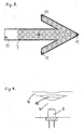
- The electronic warning device according to the invention is detailed through figures where figure:
- 1
- is an axonometric representation of an expedient form of realization of the device;
- 2
- is the circuit diagram of an expedient form of realization;
- 3
- is a frontal view of an expedient arrangement of the light-diffusing optical subsystems in the transparent frontal cover;
- 4
- is a section view of a possible optical subsystem of the transparent cover;
- 5
- is an axonometric representation of an expedient form of realization of the snap-on support;
- 6
- is an axonometric representation of a form of realization of the screw-on assembly.
- Figure 1 illustrates an expedient form of realization of the device from the back. The lightweight, flat arrow-shaped 1 housing contains an integrated 3 electrical supply, a 4 control unit affixed to an optoelectrical panel, and low-
consumption 5 lighting units; a significant part of its 2 back panel is covered by 8 a magnet. The 3 electric supply can be reached through the opening-closing panel at the base of the arrow shape; the 4 flashing lights can be operated through the 14 switch on the outside of the 1 housing. The 2 bottom plate and 6 transparent front cover of the 1 housing are secured by screws. In a given realization the 1 housing is equipped with a 13 tapped hole near the center of gravity of the arrow shape allowing for affixing a hanging assembly. - Figure 2 is the circuit diagram of an expedient form of realization, in which the 3 electrical supply comprises a few extra low voltage (AAA) batteries, the 5 lighting units are LEDs, the 4 control unit is a free-running multivibrator operated by a 14 switch.
- Figure 3 illustrates a possible optical subsystem of the transparent cover. The 6 fluorescent colored transparent cover, possibly of a material resistant to heat and ultraviolet rays is above the 5 lighting unit integrated into the optoelectronic panel attached to the back panel, separated by a small 9 air gap, and 10 collecting-dispersing lenses are fashioned in the transparent cover by varying the thickness of the transparent material. In this case the light of the LED spreading over 15 degrees is focused by the curve of the collecting-dispersing lens, then passed on dispersed over 70 degrees.
- Figure 4 illustrates an expedient arrangement of the light-dispersing optical subsystem in the 6 transparent cover of the front surface. Regarding the front surface from close up depressions can be seen above the 7 optical subsystems (eyes). In the case of the placement most expedient for light dispersion each 7 optical subsystem is positioned above a 5 lighting unit.
- Figure 3 illustrates a 15 snap-on support, which is attached to the 1 housing from the direction of the 2 back cover, and using which the device according to invention can be rigidly attached to any flat object (e.g. window glass) from its base end.
- Figure 6 shows a possible form of the 16 flat spring assembly, which can be screwed onto the 1 housing, and which allows for various types of rigid fixing according to which part of the device and in what configuration it is attached. It is expedient to configure 13 tapped holes on various points (e.g. at the base or near the center of gravity on the side ore the back plate) of the 1 housing of the device according to the invention to allow the user to find the most expedient way and position of affixing the device.
- The device according to the invention offers more of a warning than conventional warning devices, and it can also be affixed to allow for greater stability and visibility, as - thanks to its magnetic backing - it can be attached to the vertical back surface of the vehicle in one simple movement or may be affixed to a slightly opened window or door latch in the desired direction using the screw-on flat spring support. The form of realization illustrated in the figure offers reliable operation and about 10 hours of operation with long-life batteries without the need for battery change.
- The device according to the invention is economical to manufacture thanks to its inexpensive and simple parts, and offers manifold applicability and fills a void in traffic safety because of the clear warning it gives.
- References used in the illustrations:
- 1
- housing;
- 2
- bottom plate;...
- 3
- electric supply;...
- 4
- control unit;
- 5
- lighting unit;
- 6
- (transparent) cover;
- 7
- optical subsystem;
- 8
- magnet;
- 9
- air gap;
- 10
- collecting-spreading lens;
- 11
- (fastening) screw;
- 13
- tapped hole;
- 14
- switch;
- 15
- snap-on support;
- 16
- (screw-on) assembly;
Claims (6)
- An electronic warning device suitable for self-bearing attachment and emitting flashing light - characterized by a flat, arrow shaped housing with an integrated power supply (3), an integrated control unit (4), optoelectronic lighting units (5) connected to the former and attached to the back panel (2) of the housing (1); a transparent front cover (6) on the housing (1), which cover (6) comprises light-dispersing optical subsystems (7); and part of the back panel (2) being magnetically coated (8).
- The device according to claim 1 characterized by having eyes containing collecting-diffusing lenses (10) as a light-diffusing optical subsystems (7) in the transparent cover (6) above the individual lighting units (5).
- The device according to claims 1 and 2 characterized by a housing (1) made of plastic, an extra low voltage battery as a power supply (3), LEDs as lighting units (5), and the control unit (4) being a free-running multivibrator equipped with a switch (14), the transparent front cover made of fluorescent colored, plastic resistant to heat and UV-radiation, the eyes containing the collecting-dispersing lenses (10) being formulated by varying the thickness of the material of the cover (6), and having a permanently fixed thin magnetic plate on the outer surface of the back panel (2) of the housing.
- The device according to claim 1 characterized by having a snap-on support (15) that can be attached to the back panel (2) of the housing (1).
- The device according to claim 1 characterized by having a tapped hole (13) at the base end of the arrow-shaped housing (1), and a screw-on hanging assembly.
- The device according to claim 1 characterized by having a tapped hole (13) near the center of gravity of the arrow-shaped housing (1), and a screw-on hanging assembly.
Applications Claiming Priority (1)
| Application Number | Priority Date | Filing Date | Title |
|---|---|---|---|
| HU20060600119U HU3229U (en) | 2006-05-10 | 2006-05-10 | Electronic warning device |
Publications (1)
| Publication Number | Publication Date |
|---|---|
| EP1855257A1 true EP1855257A1 (en) | 2007-11-14 |
Family
ID=37499908
Family Applications (1)
| Application Number | Title | Priority Date | Filing Date |
|---|---|---|---|
| EP07462005A Withdrawn EP1855257A1 (en) | 2006-05-10 | 2007-05-04 | Electronic warning device |
Country Status (2)
| Country | Link |
|---|---|
| EP (1) | EP1855257A1 (en) |
| HU (1) | HU3229U (en) |
Cited By (1)
| Publication number | Priority date | Publication date | Assignee | Title |
|---|---|---|---|---|
| GB2529440A (en) * | 2014-08-20 | 2016-02-24 | Kenneth John Huzzey | Hazzard Alert Arrow |
Citations (7)
| Publication number | Priority date | Publication date | Assignee | Title |
|---|---|---|---|---|
| GB624588A (en) * | 1947-03-19 | 1949-06-13 | London & North Eastern Railway | Improvements in and relating to lighting fittings |
| US3242481A (en) * | 1964-01-20 | 1966-03-22 | Lasting Walter | Distress and code signaling device |
| GB2222919A (en) * | 1988-09-20 | 1990-03-21 | Safety Equipment Public Inc | Apparatus and methods for controlling a signal device |
| US5022627A (en) * | 1988-12-20 | 1991-06-11 | G.P.B. Geghelli S.R.L. | Sign projecting from vertical walls or horizontal beams |
| GB2312457A (en) * | 1996-04-24 | 1997-10-29 | Beijing Success Electronic Co | Warning triangle |
| DE19715425A1 (en) * | 1997-04-14 | 1998-10-15 | Ali Guelmez | Sign for attaching to roof of vehicle, especially taxi sign |
| US20030117063A1 (en) * | 2001-12-25 | 2003-06-26 | Hisao Tajima | Image display apparatus, method for disassembling image display apparatus and method for manufacturing image display apparatus |
-
2006
- 2006-05-10 HU HU20060600119U patent/HU3229U/en unknown
-
2007
- 2007-05-04 EP EP07462005A patent/EP1855257A1/en not_active Withdrawn
Patent Citations (7)
| Publication number | Priority date | Publication date | Assignee | Title |
|---|---|---|---|---|
| GB624588A (en) * | 1947-03-19 | 1949-06-13 | London & North Eastern Railway | Improvements in and relating to lighting fittings |
| US3242481A (en) * | 1964-01-20 | 1966-03-22 | Lasting Walter | Distress and code signaling device |
| GB2222919A (en) * | 1988-09-20 | 1990-03-21 | Safety Equipment Public Inc | Apparatus and methods for controlling a signal device |
| US5022627A (en) * | 1988-12-20 | 1991-06-11 | G.P.B. Geghelli S.R.L. | Sign projecting from vertical walls or horizontal beams |
| GB2312457A (en) * | 1996-04-24 | 1997-10-29 | Beijing Success Electronic Co | Warning triangle |
| DE19715425A1 (en) * | 1997-04-14 | 1998-10-15 | Ali Guelmez | Sign for attaching to roof of vehicle, especially taxi sign |
| US20030117063A1 (en) * | 2001-12-25 | 2003-06-26 | Hisao Tajima | Image display apparatus, method for disassembling image display apparatus and method for manufacturing image display apparatus |
Cited By (1)
| Publication number | Priority date | Publication date | Assignee | Title |
|---|---|---|---|---|
| GB2529440A (en) * | 2014-08-20 | 2016-02-24 | Kenneth John Huzzey | Hazzard Alert Arrow |
Also Published As
| Publication number | Publication date |
|---|---|
| HU3229U (en) | 2007-03-28 |
| HU0600119V0 (en) | 2006-06-28 |
Similar Documents
| Publication | Publication Date | Title |
|---|---|---|
| US8192061B2 (en) | Annular lighting fixture and method for illumination | |
| US9777910B2 (en) | LED based area lighting fixture | |
| US9134474B2 (en) | Headlamp bulb type light pipe | |
| US20100225459A1 (en) | Bicycle display lamp structure | |
| US6817743B2 (en) | Vehicle wheel illumination system | |
| BR112018000031B1 (en) | GLAZING, GLAZING FOR A BUILDING OR FOR A VEHICLE, VEHICLE USER LIGHT, AND ARRANGEMENT FOR MOUNTING A VEHICLE USER LIGHT TO THE WINDOW GLASS OF A VEHICLE | |
| CN106255617A (en) | Use the illuminator of conducting electric power plate | |
| KR101882719B1 (en) | Portable led light and warning light | |
| JP2011044394A (en) | Light guide body used for lighting fixture for vehicle | |
| EP1855257A1 (en) | Electronic warning device | |
| US20070008732A1 (en) | Illuminated bedrail for pickup trucks | |
| KR101618860B1 (en) | LED lamp for alarm | |
| JP7660751B2 (en) | Light source | |
| US20130170240A1 (en) | License Plate Illuminator | |
| US4713732A (en) | Vehicle warning system | |
| KR100812975B1 (en) | Traffic signs for pedestrian crossings with adjustable lighting angles | |
| KR20090102275A (en) | Traffic sign | |
| CN206608863U (en) | A kind of automobile day portable lighter | |
| KR200496938Y1 (en) | LED signs with improved visibility and assembly | |
| CN217928368U (en) | Electric torch | |
| EP2803911B1 (en) | Led lighting device with improved light distribution | |
| CN110553211A (en) | Vehicle lighting lamp capable of adjusting color temperature | |
| KR100823042B1 (en) | Electrodeless fluorescent lamps | |
| KR200429262Y1 (en) | Traffic signs for pedestrian crossings with adjustable lighting angles | |
| EP0406560A1 (en) | Road triangle with intermittent luminose signaling |
Legal Events
| Date | Code | Title | Description |
|---|---|---|---|
| PUAI | Public reference made under article 153(3) epc to a published international application that has entered the european phase |
Free format text: ORIGINAL CODE: 0009012 |
|
| AK | Designated contracting states |
Kind code of ref document: A1 Designated state(s): AT BE BG CH CY CZ DE DK EE ES FI FR GB GR HU IE IS IT LI LT LU LV MC MT NL PL PT RO SE SI SK TR |
|
| AX | Request for extension of the european patent |
Extension state: AL BA HR MK YU |
|
| AKX | Designation fees paid | ||
| REG | Reference to a national code |
Ref country code: DE Ref legal event code: 8566 |
|
| STAA | Information on the status of an ep patent application or granted ep patent |
Free format text: STATUS: THE APPLICATION IS DEEMED TO BE WITHDRAWN |
|
| 18D | Application deemed to be withdrawn |
Effective date: 20080515 |