EP1855199A2 - Image forming apparatus for managing application and control method therefor - Google Patents
Image forming apparatus for managing application and control method therefor Download PDFInfo
- Publication number
- EP1855199A2 EP1855199A2 EP07108086A EP07108086A EP1855199A2 EP 1855199 A2 EP1855199 A2 EP 1855199A2 EP 07108086 A EP07108086 A EP 07108086A EP 07108086 A EP07108086 A EP 07108086A EP 1855199 A2 EP1855199 A2 EP 1855199A2
- Authority
- EP
- European Patent Office
- Prior art keywords
- application
- job
- image forming
- forming apparatus
- type
- Prior art date
- Legal status (The legal status is an assumption and is not a legal conclusion. Google has not performed a legal analysis and makes no representation as to the accuracy of the status listed.)
- Withdrawn
Links
Images


Classifications
-
- G—PHYSICS
- G06—COMPUTING; CALCULATING OR COUNTING
- G06F—ELECTRIC DIGITAL DATA PROCESSING
- G06F9/00—Arrangements for program control, e.g. control units
- G06F9/06—Arrangements for program control, e.g. control units using stored programs, i.e. using an internal store of processing equipment to receive or retain programs
- G06F9/44—Arrangements for executing specific programs
- G06F9/445—Program loading or initiating
-
- H—ELECTRICITY
- H04—ELECTRIC COMMUNICATION TECHNIQUE
- H04N—PICTORIAL COMMUNICATION, e.g. TELEVISION
- H04N1/00—Scanning, transmission or reproduction of documents or the like, e.g. facsimile transmission; Details thereof
- H04N1/32—Circuits or arrangements for control or supervision between transmitter and receiver or between image input and image output device, e.g. between a still-image camera and its memory or between a still-image camera and a printer device
- H04N1/32502—Circuits or arrangements for control or supervision between transmitter and receiver or between image input and image output device, e.g. between a still-image camera and its memory or between a still-image camera and a printer device in systems having a plurality of input or output devices
- H04N1/32545—Distributing a job or task among a plurality of input devices or a plurality of output devices
- H04N1/3255—Hybrid jobs, i.e. performing different parts of the same job on different devices, e.g. colour and B/W pages on different devices
Definitions
- the present invention relates to an image forming apparatus in which an application is installed, a method for controlling the application in the image forming apparatus, and a program for executing the method.
- Digital multifunctional apparatuses that include an image scanning section such as a scanner and an image forming section such as a printer, and which handle image information from the image scanning section as digital information, are known. Such digital multifunctional apparatuses have, besides the basic document copy function, the additional function of connecting to a network. Thus, the digital multifunctional apparatuses can perform the print function of printing print data received via the network and the transmission function of transmitting image information scanned by the image scanning section via the network. Among the digital multifunctional apparatuses, some digital multifunctional apparatuses have the function of connecting to a publicly-switched telephone network (PSTN) and performing facsimile communication.
- PSTN publicly-switched telephone network
- the above-described digital multifunctional apparatuses generally have a display apparatus such as a liquid crystal display (LCD) with a certain degree of resolution.
- the digital multifunctional apparatuses can execute application programs for allowing a user to use various functions.
- Japanese Patent Laid-Open No. 2000-122853 discloses a digital multifunctional apparatus that can enhance, improve, and add functions by installing a program received via a network in the apparatus and allowing the apparatus to execute processing in accordance with the program.
- Japanese Patent Laid-Open No. 2002-287990 describes the technique of, not only installing a program in a digital multifunctional apparatus, but also performing other operations, that is, activating, deactivating, and uninstalling the installed program via a network.
- One of the aspects of our invention provides features that the applications can cooperate together to perform predetermined job processing in an image forming apparatus in which multiple applications are installed.
- the applications that cooperate together to perform predetermined job processing can be presented to the user.
- the present invention in its first aspect provides an image forming apparatus as specified in claims 1 to 11. According to a second aspect of the present invention, there is provided a control method as specified in claims 12 to 22.
- Fig. 1 is a diagram of the hierarchical structure of a digital multifunctional apparatus.
- Fig. 2 is a block diagram of the schematic configuration of an application management system for describing an application manager 110 according to a first embodiment of the present invention.
- Fig. 3 is a diagram of the structure of an application management unit 201.
- Fig. 4 is a diagram of the structure of each application definition file 401 stored in the application management unit 201.
- Fig. 5 is a sequence diagram of a process of installing an application.
- Fig. 6 is a diagram of an application install screen.
- Fig. 7 is a sequence diagram of a process of controlling an application.
- Fig. 8 is a diagram of an application control screen.
- Fig. 9 is a block diagram of the configuration of an application management system according to a second embodiment of the present invention.
- Fig. 10 is a diagram of the structure of notification information sent from a digital-multifunctional-apparatus controller 103 when a job is generated.
- Fig. 11 is a diagram of an application selection display screen.
- Figs. 12A and 12B are flowcharts of a process from job generation detection to execution of an application by the application manager 110.
- Fig. 13 is a diagram of an available-application presenting screen.
- Fig. 14 is a diagram of a connectable-application presenting screen.
- Fig. 15 is a block diagram of the configuration of an application management system according to a third embodiment of the present invention.
- Fig. 1 is a diagram of the hierarchical structure of a digital multifunctional apparatus according to a first embodiment of the present invention.
- an image forming section 101 executes an image forming process to form an image on a recording medium, such as a sheet of paper.
- the image forming process includes a series of steps of handling a sheet, transferring an image onto the sheet, and fusing the image on the sheet.
- the image forming section 101 has, for example, an ink jet printer or an electrophotographic image forming unit.
- An image scanning section 102 includes a scanner and optically scans a document image and converts the document image into digital image information.
- the image scanning section 102 outputs the digital image information to the image forming section 101 to form an image or transfers the digital image information to a facsimile unit 104 or a network interface unit 107 to transmit the digital image information via a line.
- a digital-multifunctional-apparatus controller 103 controls the operation of the image forming section 101 and the operation of the image scanning section 102.
- the digital-multifunctional-apparatus controller 103 controls the image forming section 101 and the image scanning section 102 such that document information scanned by the image scanning section 102 is copied by the image forming section 101.
- the digital-multifunctional-apparatus controller 103 includes the network interface unit 107, a print processing unit 106, the facsimile unit 104, and an operation unit controller 105 and controls information exchange among these components 104 to 107.
- the facsimile unit 104 transmits and receives a facsimile image. Specifically, the facsimile unit 104 transmits the digital image information obtained by the image scanning section 102 or decodes a received facsimile signal, which in turn is recorded by the image forming section 101.
- the operation unit controller 105 performs a control operation to generate a signal in accordance with a user operation using an operation panel of an operation unit or to display various data or messages on the operation unit (or a display unit).
- the print processing unit 106 performs a control operation to process print data input via the network interface unit 107 and to output the processed print data to the image forming section 101, thereby printing the print data.
- the network interface unit 107 controls transmission and reception of data to and from another communication apparatus via a communication line.
- a virtual machine 108 is positioned above the digital-multifunctional-apparatus controller 103.
- the virtual machine 108 is configured to control the digital-multifunctional-apparatus controller 103.
- the network interface unit 107 can be directly used from both the digital-multifunctional-apparatus controller 103 and the virtual machine 108. This enables the digital-multifunctional-apparatus controller 103 and the virtual machine 108 to independently access an external network.
- Applications A to D written in a programming language supported by an application programming interface (API) provided by the virtual machine 108 are positioned above the virtual machine 108. These applications A to D can indirectly affect the digital-multifunctional-apparatus controller 103 via the virtual machine 108 or activate the image forming section 101 and the image scanning section 102.
- API application programming interface
- An external storage controller 109 converts the image scanned by the image scanning section 102 into a data format that can be saved to an external storage by the image forming section 101 and saves the converted data to the external storage.
- the external storage controller 109 reads the data saved in the external storage and prints the data via the image forming section 101 or transmits the data to the outside via the network using the network interface unit 107.
- An application manager 110 manages the applications A to D.
- the application manager 110 accepts activation, deactivation, installing, and uninstalling of each application or receives device information generated by the digital-multifunctional-apparatus controller 103 to control each application.
- An application management system includes the above-described digital multifunctional apparatus and an application installer 204, which will be described later, connected to the digital multifunctional apparatus such that the application installer 204 and the digital multifunctional apparatus can communicate with each other.
- Fig. 2 is a block diagram of the schematic configuration of the application management system.
- the application management system includes the virtual machine 108, an application installer 204, the application manager 110, the external storage controller 109, and an external storage 111.
- the application manager 110 manages the applications.
- the external storage 111 stores a program to be installed.
- the application installer 204 may be a web browser connected to the digital multifunctional apparatus via a hyptertext transport protocol (HTTP protocol) to install and control an application from a remote environment.
- HTTP protocol hyptertext transport protocol
- the application installer 204 may install and control an application in a local environment using the operation unit (or the display unit) included in the digital multifunctional apparatus.
- the application manager 110 includes an application management unit 201, an application controller 202, and an install manager 203.
- the application management unit 201 stores a set of the name of an installed application, path information indicating the path storing a program file of the application, and an application definition file.
- the install manager 203 accepts installing, activation, and deactivation of an application from the external application installer 204.
- the application controller 202 receives information generated by the digital-multifunctional-apparatus controller 103 or information generated by the application installer 204 to control each application.
- the install manager 203 may be a servlet operating on an HTTP server to accept installing and control of each application from a remote environment via the web.
- the install manager 203 may be an applet to install and control each application in a local environment using the operation unit (or the display unit) included in the digital multifunctional apparatus.
- Fig. 3 shows the structure of the application management unit 201.
- the application management unit 201 stores a set of the name of an installed application, path information indicating the path storing a program file of the application, and an application definition file.
- Fig. 4 shows the structure of each application definition file 401 stored in the application management unit 201.
- the application definition file 401 includes the version of the definition file, the name of the application, a description of the application, the type of job that can be accepted by the application, and the type of job output by executing the application.
- the application definition file 401 further includes the memory size used by the application, information on available resources including persistence, the name of manufacturer of the application, the version of the application, or the like.
- a job is a management unit of digital image data generated in the digital-multifunctional-apparatus controller 103 using the functions of the digital multifunctional apparatus.
- the digital multifunctional apparatus generates a copy job when using the copy function, a scan job when using the scan function, a facsimile job when receiving a facsimile, and a save job when saving data to the external storage connected to the digital multifunctional apparatus.
- the type of job need not be described in each application definition file.
- the type of job may be defined according to the state of a job, depending on the job management method of the digital-multifunctional-apparatus controller 103.
- the state of a job includes, for example, the state of a job managed in a data format that can be directly analyzed by the print processing unit 106 or the state of a job managed in such a manner that digital data is compressed to be saved to the external storage.
- the type of job is described in a classified manner in each application definition file 401.
- FIG. 5 is a sequence diagram showing the process
- Fig. 6 is a diagram of an application install screen.
- the install manager 203 transmits an install form to the application installer 204 in response to a request from the application installer 204 (sequence S501).
- the install form includes, as shown in Fig. 6, a space 601 to enter the name of an application, a space 602 to enter the path storing program data of the application in the application installer 204, and a transfer button 603.
- the user Using the application installer 204, the user enters, on the install form, the application name and the path storing the program in the application installer 204 and presses the transfer button 603 (sequence S502).
- the application installer 204 transfers, as an install instruction, the name of the application to be installed and the application program data to the install manager 203 in accordance with the defined specification of the install form (sequence S503).
- the application program data contains the application definition file 401.
- the install manager 203 receives the program data sent from the application installer 204 and saves the program data in a file on the external storage 111 (sequence S504). In addition, the install manager 203 registers the path storing the program, the application name, and the application definition file 401 in the application management unit 201 (sequence S505).
- Fig. 7 is a sequence diagram showing the process
- Fig. 8 is a diagram of an application control screen.
- the install manager 203 transmits an activation setting form (or data regarding the activation setting form) to the application installer 204 in response to a request from the application installer 204 (sequence S701).
- the activation setting form includes, as shown in Fig. 8, an application name list 801 including application names and associated check boxes, an activation button 802, and a deactivation button 803.
- the application installer 204 uses the application installer 204 to transfer, as a program activation instruction, the name of the application to be activated to the install manager 203 in accordance with the defined specification of the activation setting form (sequence S703).
- the install manager 203 receives the application name sent from the application installer 204 and transfers, as a program activation instruction, the name of the application to be activated to the application controller 202 (sequence S704).
- the application controller 202 receives the name of the application to be activated, which serves as the activation instruction, from the install manager 203 and transfers a registration confirmation request to the application management unit 201, asking whether the application with that name is registered or not (sequence S705).
- the application management unit 201 When the application with that name is not registered in the application management unit 201, the application management unit 201 ends the control process shown in Fig. 7. In contrast, when the application with that name is registered in the application management unit 201, the application management unit 201 returns information indicating that the application is registered to the application controller 202.
- the application controller 202 receives the information indicating that the application is registered and sends an operation confirmation request to the application management unit 201, asking whether the application with that name is operating or not (sequence S706).
- the application management unit 201 When the application with that name is operating, the application management unit 201 ends the control process shown in Fig. 7. In contrast, when the application with that name is not operating, the application management unit 201 obtains the path information indicating the path storing the program file of that application on the basis of the application name. On the basis of the path information, the application management unit 201 loads the program data file from the external storage 111 and activates the application (sequence S707).
- the digital multifunctional apparatus includes the application manager 110, which manages the operation of multiple applications operating on the virtual machine 108, and the install manager 203 operating on the application manager 110. Therefore, an application can be installed, activated, or deactivated in the digital multifunctional apparatus using, for example, the application installer 204 at a remote place. In other words, a program can be easily added, activated, or deleted without affecting another application running on an embedded apparatus, such as the digital multifunctional apparatus.
- Fig. 9 is a block diagram showing the configuration of an application management system according to a second embodiment.
- the application management system shown in Fig. 9 includes an additional screen controller 901 in the application manager 110.
- the screen controller 901 controls the display operation of an operation panel 112 of the digital multifunctional apparatus and accepts inputs from the operation panel 112.
- the operation panel 112 of the digital multifunctional apparatus has an interface for presenting information to the user and an interface for accepting information from the user. That is, the operation panel 112 includes, for example, a touch-panel-type liquid crystal screen and push buttons serving as the input interface.
- the application manager 110 When activated, the application manager 110 registers a job generation notification request in the digital-multifunctional-apparatus controller 103. This allows the digital-multifunctional-apparatus controller 103 to send notification information 1001 to the application manager 110 when a job serving as digital data to be processed by the digital multifunctional apparatus is generated.
- the job generation timing is as follows. For example, image data scanned by the image scanning section 102 is converted into digital image information, and this digital image information is generated as a scan job in the digital-multifunctional-apparatus controller 103. For example, a facsimile signal received by the facsimile unit 104 is decoded, and this decoded signal is generated as a facsimile job in the digital-multifunctional-apparatus controller 103. For example, print data received via the network interface unit 107 is processed, and the processed data is generated as a print job in the digital-multifunctional-apparatus controller 103.
- the digital-multifunctional-apparatus controller 103 sends the notification information 1001 to the device that has registered the job generation notification request, namely, the application manager 110.
- the notification information 1001 includes the job state indicating the state in which the job is generated, the type of the generated job, a job handle for managing the job in the digital-multifunctional-apparatus controller 103, and a job identifier for specifying the job.
- Fig. 10 shows the structure of the notification information 1001 sent from the digital-multifunctional-apparatus controller 103 when the job is generated.
- the application manager 110 On the basis of the notification information 1001, the application manager 110 detects that the job in a controllable format is generated in the digital-multifunctional-apparatus controller 103. Using the job handle included in the notification information 1001, the application manager 110 controls the generated job for the digital-multifunctional-apparatus controller 103.
- the method of detecting, by the application manager 110, that a job is generated in the digital-multifunctional-apparatus controller 103 is not limited to the above method.
- the application manager 110 may periodically check the digital-multifunctional-apparatus controller 103 to see whether a job has been generated or not.
- the application manager 110 controls the operation unit controller 105 via the digital-multifunctional-apparatus controller 103 to display a check box 1101 whereby the user selects whether to display available applications, as shown in Fig. 11.
- Fig. 11 is a diagram of an application selection display screen.
- the application manager 110 may additionally have the function of managing user information. According to the user, an application that has been displayed once may not be automatically displayed on the operation panel 112. In this case, the application manager 110 obtains login information including user information of the user via the operation panel 112, distinguishes the user, and manages information identifying the application that has been displayed to that user. The application manager 110 determines, according to the user, whether the application has already been displayed once. In contrast, the application manager 110 may automatically display a newly installed application on the operation panel 112.
- FIGs. 12A and 12B include flowcharts of a process from job generation detection to execution of an application by the application manager 110.
- Fig. 13 is a diagram of an available-application presenting screen.
- Fig. 14 is a connectable-application presenting screen.
- the digital-multifunctional-apparatus controller 103 When the user wants to use one of the known functions of the digital multifunctional apparatus, such as the function of sending a copied or scanned image via email, the digital-multifunctional-apparatus controller 103 generates a job and sends the notification information 1001 to notify the application manager 110 of generation of a job (step S1201).
- the application manager 110 searches the acceptable job types described in the corresponding application definition files 401 managed in the application management unit 201 (step S1202).
- the application manager 110 determines whether the type of job included in the sent notification information 1001 matches any of the acceptable job types described in the application definition files 401 managed in the application management unit 201 (step S1203). When it is determined that the two job types match each other ("YES” in step S1203), the application manager 110 proceeds to step S1204. Otherwise (“NO” in step S1203), the process shown in Figs. 12A and 12B is ended.
- step S1204 the application manager 110 uses the job handle in the notification information 1001 to copy the generated job and stores the copied job as a "saved job" on the external storage 111.
- the application manager 110 specifies the job identifier and saves the copied job.
- the job identifier is required to be unique only within the digital multifunctional apparatus.
- the application manager 110 generates, for example, a universal unique identifier (UUID) and uses this UUID as a job identifier.
- UUID universal unique identifier
- the application manager 110 determines whether the user wants to continue using the known function of the digital multifunctional apparatus, such as the copy function or the data transfer function via a network (step S1205). In this case, the application manager 110 determines whether to continue using the function on the basis of preset information. To this end, the selection display screen shown in Fig. 11 may include an additional check box to be checked when the user wants to continue using the function. On the basis of the check box, the determination whether the user wants to continue using the function may be made.
- step S1205 When it is determined to continue using the function ("YES" in step S1205), the application manager 110 proceeds to step S1207. In contrast, when it is determined not to continue using the function ("NO" in step S1205), the application manager 110 proceeds to step S1206.
- step S1206 the application manager 110 uses the job handle in the sent notification information 1001 to control deletion of the generated job, thereby deleting the generated job.
- step S1207 the application manager 110 obtains the job handle of the job copied and saved in step S1204.
- the application manager 110 receives and saves the notification information 1001 serving as a generation notification of the saved job, which is issued by the external storage 111.
- the application manager 110 checks the job identifier set in the notification information 1001 against the job identifier specified in step S1204 to specify the notification information 1001 regarding the generation notification of the corresponding copied job.
- the application manager 110 then obtains the job handle in the specified notification information 1001. As has been described above, the application manager 110 uses the job handle to control deletion of the generated job, thereby deleting the generated job.
- the digital-multifunctional-apparatus controller 103 may be structured to return the job handle of the saved job to the application manager 110. With this structure, the application manager 110 need not specify the job identifier in step S1204.
- the application manager 110 sends, to the screen controller 901, the application definition file 401 of the application in which the type of job is determined in step S1203 to match the acceptable job type.
- the screen controller 901 displays the application corresponding to the application definition file 401 as an available application, as shown in Fig. 13 (step S1208).
- the available-application presenting screen is displayed on the operation panel 112 and includes an area 1301 presenting the name of an available application and a description of the application and a selection button 1302 for selecting the application.
- the available-application presenting screen further includes an area 1303 for displaying the names of applications that have already been selected, an execution button 1304 for starting sequential execution of the applications displayed in the area 1303, and a close button 1305 for canceling the process.
- a method of displaying the area 1303 on the operation panel 112 will be described later.
- the screen controller 901 in step S1209 searches the application definition files 401 on the basis of the output job type included in the application definition file 401 of the selected application. That is, the screen controller 901 searches the application management unit 201 for the application having the acceptable job type that matches the output job type, the acceptable job type being described in the corresponding application definition file 401.
- the screen controller 901 displays the application, which is detected in step S1209 as a connectable application (step S1210).
- the connectable-application presenting screen shown in Fig. 14 includes, besides the elements of the available-application presenting screen shown in Fig. 13, an additional return button 1306.
- the user can select a plurality of applications on the available-application presenting screen shown in Fig. 13.
- the screen controller 901 displays the connectable-application presenting screen shown in Fig. 14 for each of the selected applications.
- the screen controller 901 notifies the application controller 202 of the names of the selected applications.
- the application controller 202 obtains path information of an application corresponding to one of the application names, which is stored in the application management unit 201, loads the application from the external storage 111, and executes the application.
- the application controller 202 sends job handle information included in the notification information 1001 sent from the digital-multifunctional-apparatus controller 103 as additional information to the application (step S1211).
- the application controller 202 detects completion of processing performed by the activated application.
- the application controller 202 receives a job handle of the generated job (step S1212).
- the application controller 202 determines whether there is an application specified to be connected (step S1213). When it is determined that there is an application specified to be connected ("YES” in step S1213), the application controller 202 proceeds to step S1214. In contrast, when it is determined that there is no application to be connected ("NO" in step S1213), the application controller 202 proceeds to step S1215.
- step S1214 on the basis of the name of the application specified to be connected, the application controller 202 obtains path information of the application from the application management unit 201. On basis of the path information, the application controller 202 activates the application specified to be connected. In step S1214, the application controller 202 specifies the received job handle and activates the application specified to be connected.
- step S1215 the application controller 202 determines whether there is another application whose selection button 1302 has been selected (selected application). If it is determined that there is another selected application ("YES” in step S1215), the application controller 202 returns to step S1211. In contrast, if it is determined that there is no more selected application ("NO” in step S1215), the application controller 202 ends the process shown in Figs. 12A and 12B.
- the application controller 202 continues executing the process from step S1211 to step S1215 until the execution of all the selected or connected applications is completed.
- the digital multifunctional apparatus when multiple applications are installed in the digital multifunctional apparatus, the user can simultaneously use the applications that can be executed by the same operation without needing to perform multiple operations.
- the digital multifunctional apparatus becomes user-friendlier.
- multiple applications can be connected and used. This further enhances the user-friendliness of the digital multifunctional apparatus.
- the known functions of the digital multifunctional apparatus can be continuously performed, and one operation can achieve various output results.
- the user can easily understand available applications in conjunction with operating the digital multifunctional apparatus. Furthermore, the user can easily select and execute applications installed in the digital multifunctional apparatus.
- Fig. 15 is a block diagram of the configuration of an application management system according to a third embodiment.
- the application management system shown in Fig. 15 installs, in the external storage 111, a management application 1501 for managing installed applications using the application manager 110.
- the management application 1501 can communicate with the application management unit 201 and the application controller 202 included in the application manager 110. Also, the management application 1501 controls the display operation of the operation panel 112 of the digital multifunctional apparatus and accepts inputs from the operation panel 112.
- the operation panel 112 of the digital multifunctional apparatus has an interface for presenting information to the user and an interface for accepting information from the user. That is, the operation panel 112 includes, for example, a touch-panel-type liquid crystal screen and push buttons serving as the input interface.
- the management application 1501 When activated, the management application 1501 registers a job generation notification request in the digital-multifunctional-apparatus controller 103. This allows the digital-multifunctional-apparatus controller 103 to send the notification information 1001 to the management application 1501 when a job serving as digital data to be processed by the digital multifunctional apparatus is generated.
- the job generation timing is as follows. For example, image data scanned by the image scanning section 102 is converted into digital image information, and this digital image information is generated as a scan job in the digital-multifunctional-apparatus controller 103. For example, a facsimile signal received by the facsimile unit 104 is decoded, and this decoded signal is generated as a facsimile job in the digital-multifunctional-apparatus controller 103. For example, print data received via the network interface unit 107 is processed, and the processed data is generated as a print job in the digital-multifunctional-apparatus controller 103.
- the digital-multifunctional-apparatus controller 103 sends the notification information 1001 to the device that has registered the job generation notification request, namely, the management application 1501.
- the notification information 1001 includes the job state indicating the state in which the job is generated, the type of the generated job, the job handle for managing the job in the digital-multifunctional-apparatus controller 103, and the job identifier for specifying the job.
- the management application 1501 On the basis of the notification information 1001, the management application 1501 detects that the job in a controllable format is generated in the digital-multifunctional-apparatus controller 103. Using the job handle included in the notification information 1001, the management application 1501 controls the generated job for the digital-multifunctional-apparatus controller 103.
- the method of detecting, by the management application 1501, that a job is generated in the digital-multifunctional-apparatus controller 103 is not limited to the above method.
- the management application 1501 can periodically check the digital-multifunctional-apparatus controller 103 to see whether a job is generated or not.
- the management application 1501 can perform processing similar to that performed by the application manager 110 of the first and second embodiments, thereby implementing the application management method described in the first and second embodiments.
- the management application 1501 can be activated, deactivated, installed, and uninstalled. That is, the application management method described in the first and second embodiments can be performed only when a specific condition is satisfied or a specific user uses the digital multifunctional apparatus. This is advantageous in an apparatus with limited hardware resources, such as an embedded apparatus.
- the applications can cooperate together to perform common processing.
- the effective applications that cooperate together to perform common processing can be presented to the user.
- Exemplarily applications include a scanned-data processing application, a document management application, various image processing applications, and an email sending application.
- the digital-multifunctional-apparatus controller 103 generates a job and sends the notification information 1001 to notify the application manager 110 of generation of a job.
- the application manager 110 copies the job on the basis of a job handle included in the sent notification information 1001 and saves the copied job as a "saved job" on the external storage 111.
- the application manager 110 specifies the job identifier and saves the copied job.
- the application manager 110 When the application manager 110 detects the generation of the saved job, and when the job identifier of the generated job matches the specified job identifier, the application manager 110 maintains the job handle of that job.
- the application manager 110 searches for an application in which a scan job is registered as the acceptable job type. As a result, the scanned-data processing application is displayed as an available application.
- the user selects the scanned-data processing application.
- the type of job output by the scanned-data processing application is a print job
- the acceptable job type of the document management application is a print job.
- the document management application is displayed as a connectable application.
- the names of the applications to be connected are sent to the application controller 202.
- the application controller 202 activates the scanned-data processing application and sends the job handle to the scanned-data processing application.
- the scanned-data processing application processes the scanned data.
- a print job is generated, and the job handle of the print job is returned to the application controller 202.
- the application controller 202 sends the job handle to the document management application and activates the document management application.
- the document management application registers and updates a document in a box.
Abstract
Description
- The present invention relates to an image forming apparatus in which an application is installed, a method for controlling the application in the image forming apparatus, and a program for executing the method.
- Digital multifunctional apparatuses that include an image scanning section such as a scanner and an image forming section such as a printer, and which handle image information from the image scanning section as digital information, are known. Such digital multifunctional apparatuses have, besides the basic document copy function, the additional function of connecting to a network. Thus, the digital multifunctional apparatuses can perform the print function of printing print data received via the network and the transmission function of transmitting image information scanned by the image scanning section via the network. Among the digital multifunctional apparatuses, some digital multifunctional apparatuses have the function of connecting to a publicly-switched telephone network (PSTN) and performing facsimile communication.
- The above-described digital multifunctional apparatuses generally have a display apparatus such as a liquid crystal display (LCD) with a certain degree of resolution. The digital multifunctional apparatuses can execute application programs for allowing a user to use various functions.
- For example,
Japanese Patent Laid-Open No. 2000-122853 -
Japanese Patent Laid-Open No. 2002-287990 - One of the aspects of our invention provides features that the applications can cooperate together to perform predetermined job processing in an image forming apparatus in which multiple applications are installed.
- In one of the other aspects of our invention, the applications that cooperate together to perform predetermined job processing can be presented to the user.
- The present invention in its first aspect provides an image forming apparatus as specified in claims 1 to 11. According to a second aspect of the present invention, there is provided a control method as specified in claims 12 to 22.
- Other features and advantages of the present invention will be apparent from the following description taken in conjunction with the accompanying drawings, in which like reference characters designate the same or similar parts throughout thereof.
- Fig. 1 is a diagram of the hierarchical structure of a digital multifunctional apparatus.
- Fig. 2 is a block diagram of the schematic configuration of an application management system for describing an
application manager 110 according to a first embodiment of the present invention. - Fig. 3 is a diagram of the structure of an
application management unit 201. - Fig. 4 is a diagram of the structure of each
application definition file 401 stored in theapplication management unit 201. - Fig. 5 is a sequence diagram of a process of installing an application.
- Fig. 6 is a diagram of an application install screen.
- Fig. 7 is a sequence diagram of a process of controlling an application.
- Fig. 8 is a diagram of an application control screen.
- Fig. 9 is a block diagram of the configuration of an application management system according to a second embodiment of the present invention.
- Fig. 10 is a diagram of the structure of notification information sent from a digital-multifunctional-
apparatus controller 103 when a job is generated. - Fig. 11 is a diagram of an application selection display screen.
- Figs. 12A and 12B are flowcharts of a process from job generation detection to execution of an application by the
application manager 110. - Fig. 13 is a diagram of an available-application presenting screen.
- Fig. 14 is a diagram of a connectable-application presenting screen.
- Fig. 15 is a block diagram of the configuration of an application management system according to a third embodiment of the present invention.
- Embodiments of the present invention will now be described with reference to the drawings.
- Fig. 1 is a diagram of the hierarchical structure of a digital multifunctional apparatus according to a first embodiment of the present invention. Referring to Fig. 1, an
image forming section 101 executes an image forming process to form an image on a recording medium, such as a sheet of paper. The image forming process includes a series of steps of handling a sheet, transferring an image onto the sheet, and fusing the image on the sheet. Theimage forming section 101 has, for example, an ink jet printer or an electrophotographic image forming unit. - An
image scanning section 102 includes a scanner and optically scans a document image and converts the document image into digital image information. Theimage scanning section 102 outputs the digital image information to theimage forming section 101 to form an image or transfers the digital image information to afacsimile unit 104 or anetwork interface unit 107 to transmit the digital image information via a line. - A digital-multifunctional-
apparatus controller 103 controls the operation of theimage forming section 101 and the operation of theimage scanning section 102. For example, the digital-multifunctional-apparatus controller 103 controls theimage forming section 101 and theimage scanning section 102 such that document information scanned by theimage scanning section 102 is copied by theimage forming section 101. The digital-multifunctional-apparatus controller 103 includes thenetwork interface unit 107, aprint processing unit 106, thefacsimile unit 104, and anoperation unit controller 105 and controls information exchange among thesecomponents 104 to 107. - The
facsimile unit 104 transmits and receives a facsimile image. Specifically, thefacsimile unit 104 transmits the digital image information obtained by theimage scanning section 102 or decodes a received facsimile signal, which in turn is recorded by theimage forming section 101. - The
operation unit controller 105 performs a control operation to generate a signal in accordance with a user operation using an operation panel of an operation unit or to display various data or messages on the operation unit (or a display unit). Theprint processing unit 106 performs a control operation to process print data input via thenetwork interface unit 107 and to output the processed print data to theimage forming section 101, thereby printing the print data. Thenetwork interface unit 107 controls transmission and reception of data to and from another communication apparatus via a communication line. - A
virtual machine 108 is positioned above the digital-multifunctional-apparatus controller 103. Thevirtual machine 108 is configured to control the digital-multifunctional-apparatus controller 103. - The
network interface unit 107 can be directly used from both the digital-multifunctional-apparatus controller 103 and thevirtual machine 108. This enables the digital-multifunctional-apparatus controller 103 and thevirtual machine 108 to independently access an external network. - Applications A to D written in a programming language supported by an application programming interface (API) provided by the
virtual machine 108 are positioned above thevirtual machine 108. These applications A to D can indirectly affect the digital-multifunctional-apparatus controller 103 via thevirtual machine 108 or activate theimage forming section 101 and theimage scanning section 102. - An
external storage controller 109 converts the image scanned by theimage scanning section 102 into a data format that can be saved to an external storage by theimage forming section 101 and saves the converted data to the external storage. Theexternal storage controller 109 reads the data saved in the external storage and prints the data via theimage forming section 101 or transmits the data to the outside via the network using thenetwork interface unit 107. - An
application manager 110 manages the applications A to D. Theapplication manager 110 accepts activation, deactivation, installing, and uninstalling of each application or receives device information generated by the digital-multifunctional-apparatus controller 103 to control each application. - An application management system according to the first embodiment includes the above-described digital multifunctional apparatus and an
application installer 204, which will be described later, connected to the digital multifunctional apparatus such that theapplication installer 204 and the digital multifunctional apparatus can communicate with each other. - Fig. 2 is a block diagram of the schematic configuration of the application management system. As shown in Fig. 2, the application management system includes the
virtual machine 108, anapplication installer 204, theapplication manager 110, theexternal storage controller 109, and anexternal storage 111. As has been described above, theapplication manager 110 manages the applications. Theexternal storage 111 stores a program to be installed. - The
application installer 204 may be a web browser connected to the digital multifunctional apparatus via a hyptertext transport protocol (HTTP protocol) to install and control an application from a remote environment. Alternatively, theapplication installer 204 may install and control an application in a local environment using the operation unit (or the display unit) included in the digital multifunctional apparatus. As shown in Fig. 2, theapplication manager 110 includes anapplication management unit 201, anapplication controller 202, and an installmanager 203. - The
application management unit 201 stores a set of the name of an installed application, path information indicating the path storing a program file of the application, and an application definition file. The installmanager 203 accepts installing, activation, and deactivation of an application from theexternal application installer 204. Theapplication controller 202 receives information generated by the digital-multifunctional-apparatus controller 103 or information generated by theapplication installer 204 to control each application. - The install
manager 203 may be a servlet operating on an HTTP server to accept installing and control of each application from a remote environment via the web. Alternatively, the installmanager 203 may be an applet to install and control each application in a local environment using the operation unit (or the display unit) included in the digital multifunctional apparatus. - Fig. 3 shows the structure of the
application management unit 201. As has been described above, theapplication management unit 201 stores a set of the name of an installed application, path information indicating the path storing a program file of the application, and an application definition file. - Fig. 4 shows the structure of each
application definition file 401 stored in theapplication management unit 201. As shown in Fig. 4, theapplication definition file 401 includes the version of the definition file, the name of the application, a description of the application, the type of job that can be accepted by the application, and the type of job output by executing the application. As shown in Fig. 4, theapplication definition file 401 further includes the memory size used by the application, information on available resources including persistence, the name of manufacturer of the application, the version of the application, or the like. - A job is a management unit of digital image data generated in the digital-multifunctional-
apparatus controller 103 using the functions of the digital multifunctional apparatus. For example, the digital multifunctional apparatus generates a copy job when using the copy function, a scan job when using the scan function, a facsimile job when receiving a facsimile, and a save job when saving data to the external storage connected to the digital multifunctional apparatus. - There may be only one type of job, depending on the job management method of the digital-multifunctional-
apparatus controller 103. In this case, the type of job need not be described in each application definition file. In contrast, the type of job may be defined according to the state of a job, depending on the job management method of the digital-multifunctional-apparatus controller 103. The state of a job includes, for example, the state of a job managed in a data format that can be directly analyzed by theprint processing unit 106 or the state of a job managed in such a manner that digital data is compressed to be saved to the external storage. To define the type of job according to the job state, the type of job is described in a classified manner in eachapplication definition file 401. - Next, an exemplary process of installing an application will be described with reference to Figs. 5 and 6. Fig. 5 is a sequence diagram showing the process, and Fig. 6 is a diagram of an application install screen.
- As shown in Fig. 5, the install
manager 203 transmits an install form to theapplication installer 204 in response to a request from the application installer 204 (sequence S501). The install form includes, as shown in Fig. 6, aspace 601 to enter the name of an application, aspace 602 to enter the path storing program data of the application in theapplication installer 204, and atransfer button 603. - Using the
application installer 204, the user enters, on the install form, the application name and the path storing the program in theapplication installer 204 and presses the transfer button 603 (sequence S502). Theapplication installer 204 transfers, as an install instruction, the name of the application to be installed and the application program data to the installmanager 203 in accordance with the defined specification of the install form (sequence S503). At this point, the application program data contains theapplication definition file 401. - The install
manager 203 receives the program data sent from theapplication installer 204 and saves the program data in a file on the external storage 111 (sequence S504). In addition, the installmanager 203 registers the path storing the program, the application name, and theapplication definition file 401 in the application management unit 201 (sequence S505). - Next, an exemplary process of controlling an application will be described with reference to Figs. 7 and 8. Fig. 7 is a sequence diagram showing the process, and Fig. 8 is a diagram of an application control screen.
- As shown in Fig. 7, the install
manager 203 transmits an activation setting form (or data regarding the activation setting form) to theapplication installer 204 in response to a request from the application installer 204 (sequence S701). The activation setting form includes, as shown in Fig. 8, anapplication name list 801 including application names and associated check boxes, anactivation button 802, and adeactivation button 803. - Using the
application installer 204, the user checks on the check box of a desired application to activate in theapplication name list 801 on the activation setting form and presses the activation button 802 (sequence S702). Then, theapplication installer 204 transfers, as a program activation instruction, the name of the application to be activated to the installmanager 203 in accordance with the defined specification of the activation setting form (sequence S703). - The install
manager 203 receives the application name sent from theapplication installer 204 and transfers, as a program activation instruction, the name of the application to be activated to the application controller 202 (sequence S704). - The
application controller 202 receives the name of the application to be activated, which serves as the activation instruction, from the installmanager 203 and transfers a registration confirmation request to theapplication management unit 201, asking whether the application with that name is registered or not (sequence S705). - When the application with that name is not registered in the
application management unit 201, theapplication management unit 201 ends the control process shown in Fig. 7. In contrast, when the application with that name is registered in theapplication management unit 201, theapplication management unit 201 returns information indicating that the application is registered to theapplication controller 202. - The
application controller 202 receives the information indicating that the application is registered and sends an operation confirmation request to theapplication management unit 201, asking whether the application with that name is operating or not (sequence S706). - When the application with that name is operating, the
application management unit 201 ends the control process shown in Fig. 7. In contrast, when the application with that name is not operating, theapplication management unit 201 obtains the path information indicating the path storing the program file of that application on the basis of the application name. On the basis of the path information, theapplication management unit 201 loads the program data file from theexternal storage 111 and activates the application (sequence S707). - The digital multifunctional apparatus according to the first embodiment includes the
application manager 110, which manages the operation of multiple applications operating on thevirtual machine 108, and the installmanager 203 operating on theapplication manager 110. Therefore, an application can be installed, activated, or deactivated in the digital multifunctional apparatus using, for example, theapplication installer 204 at a remote place. In other words, a program can be easily added, activated, or deleted without affecting another application running on an embedded apparatus, such as the digital multifunctional apparatus. - Now, other exemplary embodiments using the above-described digital multifunctional apparatus will be described as second and third embodiments. Second Embodiment
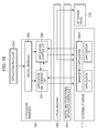
- Fig. 9 is a block diagram showing the configuration of an application management system according to a second embodiment. In comparison with the application management system shown in Fig. 2, the application management system shown in Fig. 9 includes an
additional screen controller 901 in theapplication manager 110. Thescreen controller 901 controls the display operation of anoperation panel 112 of the digital multifunctional apparatus and accepts inputs from theoperation panel 112. - The
operation panel 112 of the digital multifunctional apparatus has an interface for presenting information to the user and an interface for accepting information from the user. That is, theoperation panel 112 includes, for example, a touch-panel-type liquid crystal screen and push buttons serving as the input interface. - When activated, the
application manager 110 registers a job generation notification request in the digital-multifunctional-apparatus controller 103. This allows the digital-multifunctional-apparatus controller 103 to sendnotification information 1001 to theapplication manager 110 when a job serving as digital data to be processed by the digital multifunctional apparatus is generated. - The job generation timing is as follows. For example, image data scanned by the
image scanning section 102 is converted into digital image information, and this digital image information is generated as a scan job in the digital-multifunctional-apparatus controller 103. For example, a facsimile signal received by thefacsimile unit 104 is decoded, and this decoded signal is generated as a facsimile job in the digital-multifunctional-apparatus controller 103. For example, print data received via thenetwork interface unit 107 is processed, and the processed data is generated as a print job in the digital-multifunctional-apparatus controller 103. - At the time the job is generated, the digital-multifunctional-
apparatus controller 103 sends thenotification information 1001 to the device that has registered the job generation notification request, namely, theapplication manager 110. As shown in Fig. 10, thenotification information 1001 includes the job state indicating the state in which the job is generated, the type of the generated job, a job handle for managing the job in the digital-multifunctional-apparatus controller 103, and a job identifier for specifying the job. Fig. 10 shows the structure of thenotification information 1001 sent from the digital-multifunctional-apparatus controller 103 when the job is generated. - On the basis of the
notification information 1001, theapplication manager 110 detects that the job in a controllable format is generated in the digital-multifunctional-apparatus controller 103. Using the job handle included in thenotification information 1001, theapplication manager 110 controls the generated job for the digital-multifunctional-apparatus controller 103. - The method of detecting, by the
application manager 110, that a job is generated in the digital-multifunctional-apparatus controller 103 is not limited to the above method. For example, theapplication manager 110 may periodically check the digital-multifunctional-apparatus controller 103 to see whether a job has been generated or not. - Next, the
application manager 110 controls theoperation unit controller 105 via the digital-multifunctional-apparatus controller 103 to display acheck box 1101 whereby the user selects whether to display available applications, as shown in Fig. 11. Fig. 11 is a diagram of an application selection display screen. - When the
check box 1101 is not checked by the user, an application management method described in the second embodiment is not performed, and the general functions of the digital multifunctional apparatus are performed. - Alternatively, for example, the
application manager 110 may additionally have the function of managing user information. According to the user, an application that has been displayed once may not be automatically displayed on theoperation panel 112. In this case, theapplication manager 110 obtains login information including user information of the user via theoperation panel 112, distinguishes the user, and manages information identifying the application that has been displayed to that user. Theapplication manager 110 determines, according to the user, whether the application has already been displayed once. In contrast, theapplication manager 110 may automatically display a newly installed application on theoperation panel 112. - With reference to Figs. 12A and 12B, 13, and 14, an exemplary operation of the digital multifunctional apparatus in the case that the
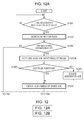
check box 1101 is checked will be described. Figs. 12A and 12B include flowcharts of a process from job generation detection to execution of an application by theapplication manager 110. Fig. 13 is a diagram of an available-application presenting screen. Fig. 14 is a connectable-application presenting screen. - When the user wants to use one of the known functions of the digital multifunctional apparatus, such as the function of sending a copied or scanned image via email, the digital-multifunctional-
apparatus controller 103 generates a job and sends thenotification information 1001 to notify theapplication manager 110 of generation of a job (step S1201). - On the basis of the type of job included in the sent
notification information 1001, theapplication manager 110 searches the acceptable job types described in the corresponding application definition files 401 managed in the application management unit 201 (step S1202). - On the basis of the search result, the
application manager 110 determines whether the type of job included in the sentnotification information 1001 matches any of the acceptable job types described in the application definition files 401 managed in the application management unit 201 (step S1203). When it is determined that the two job types match each other ("YES" in step S1203), theapplication manager 110 proceeds to step S1204. Otherwise ("NO" in step S1203), the process shown in Figs. 12A and 12B is ended. - In step S1204, the
application manager 110 uses the job handle in thenotification information 1001 to copy the generated job and stores the copied job as a "saved job" on theexternal storage 111. In this case, theapplication manager 110 specifies the job identifier and saves the copied job. The job identifier is required to be unique only within the digital multifunctional apparatus. Theapplication manager 110 generates, for example, a universal unique identifier (UUID) and uses this UUID as a job identifier. - Next, the
application manager 110 determines whether the user wants to continue using the known function of the digital multifunctional apparatus, such as the copy function or the data transfer function via a network (step S1205). In this case, theapplication manager 110 determines whether to continue using the function on the basis of preset information. To this end, the selection display screen shown in Fig. 11 may include an additional check box to be checked when the user wants to continue using the function. On the basis of the check box, the determination whether the user wants to continue using the function may be made. - When it is determined to continue using the function ("YES" in step S1205), the
application manager 110 proceeds to step S1207. In contrast, when it is determined not to continue using the function ("NO" in step S1205), theapplication manager 110 proceeds to step S1206. - In step S1206, the
application manager 110 uses the job handle in the sentnotification information 1001 to control deletion of the generated job, thereby deleting the generated job. - In step S1207, the
application manager 110 obtains the job handle of the job copied and saved in step S1204. For example, when the copied job is saved in step S1204, theapplication manager 110 receives and saves thenotification information 1001 serving as a generation notification of the saved job, which is issued by theexternal storage 111. Theapplication manager 110 checks the job identifier set in thenotification information 1001 against the job identifier specified in step S1204 to specify thenotification information 1001 regarding the generation notification of the corresponding copied job. Theapplication manager 110 then obtains the job handle in the specifiednotification information 1001. As has been described above, theapplication manager 110 uses the job handle to control deletion of the generated job, thereby deleting the generated job. - When the
application manager 110 copies the job and saves the copied job in step S1204, the digital-multifunctional-apparatus controller 103 may be structured to return the job handle of the saved job to theapplication manager 110. With this structure, theapplication manager 110 need not specify the job identifier in step S1204. - The
application manager 110 sends, to thescreen controller 901, theapplication definition file 401 of the application in which the type of job is determined in step S1203 to match the acceptable job type. On the basis of the receivedapplication definition file 401, thescreen controller 901 displays the application corresponding to theapplication definition file 401 as an available application, as shown in Fig. 13 (step S1208). - As shown in Fig. 13, the available-application presenting screen is displayed on the
operation panel 112 and includes anarea 1301 presenting the name of an available application and a description of the application and aselection button 1302 for selecting the application. The available-application presenting screen further includes anarea 1303 for displaying the names of applications that have already been selected, anexecution button 1304 for starting sequential execution of the applications displayed in thearea 1303, and aclose button 1305 for canceling the process. A method of displaying thearea 1303 on theoperation panel 112 will be described later. - Referring to Fig. 13, the user presses the
selection button 1302 of one of the applications that the user wants to use. Detecting that theselection button 1302 is pressed, thescreen controller 901 in step S1209 searches the application definition files 401 on the basis of the output job type included in theapplication definition file 401 of the selected application. That is, thescreen controller 901 searches theapplication management unit 201 for the application having the acceptable job type that matches the output job type, the acceptable job type being described in the correspondingapplication definition file 401. - As shown in Fig. 14, after processing performed by the application selected by the user is completed, the
screen controller 901 displays the application, which is detected in step S1209 as a connectable application (step S1210). The connectable-application presenting screen shown in Fig. 14 includes, besides the elements of the available-application presenting screen shown in Fig. 13, anadditional return button 1306. - The user can select a plurality of applications on the available-application presenting screen shown in Fig. 13. When the user selects multiple applications, the
screen controller 901 displays the connectable-application presenting screen shown in Fig. 14 for each of the selected applications. - When the user completes a series of application selecting operations and presses the
execution button 1304 shown in Fig. 13, the selected applications are sequentially executed. - With continued reference to Figs. 12A and 12B, the operation of the digital multifunctional apparatus in the case that the user selects applications and presses the
execution button 1304 will be described. - When the
execution button 1304 is pressed, thescreen controller 901 notifies theapplication controller 202 of the names of the selected applications. In response to the notification, theapplication controller 202 obtains path information of an application corresponding to one of the application names, which is stored in theapplication management unit 201, loads the application from theexternal storage 111, and executes the application. In this case, theapplication controller 202 sends job handle information included in thenotification information 1001 sent from the digital-multifunctional-apparatus controller 103 as additional information to the application (step S1211). - Then, the
application controller 202 detects completion of processing performed by the activated application. When the application has generated a job, theapplication controller 202 receives a job handle of the generated job (step S1212). - After the completion of the processing performed by the application, the
application controller 202 determines whether there is an application specified to be connected (step S1213). When it is determined that there is an application specified to be connected ("YES" in step S1213), theapplication controller 202 proceeds to step S1214. In contrast, when it is determined that there is no application to be connected ("NO" in step S1213), theapplication controller 202 proceeds to step S1215. - In step S1214, on the basis of the name of the application specified to be connected, the
application controller 202 obtains path information of the application from theapplication management unit 201. On basis of the path information, theapplication controller 202 activates the application specified to be connected. In step S1214, theapplication controller 202 specifies the received job handle and activates the application specified to be connected. - In step S1215, the
application controller 202 determines whether there is another application whoseselection button 1302 has been selected (selected application). If it is determined that there is another selected application ("YES" in step S1215), theapplication controller 202 returns to step S1211. In contrast, if it is determined that there is no more selected application ("NO" in step S1215), theapplication controller 202 ends the process shown in Figs. 12A and 12B. - The
application controller 202 continues executing the process from step S1211 to step S1215 until the execution of all the selected or connected applications is completed. - As has been described above, according to the second embodiment, when multiple applications are installed in the digital multifunctional apparatus, the user can simultaneously use the applications that can be executed by the same operation without needing to perform multiple operations. Thus, the digital multifunctional apparatus becomes user-friendlier. Depending on the type of job output by each application, multiple applications can be connected and used. This further enhances the user-friendliness of the digital multifunctional apparatus. The known functions of the digital multifunctional apparatus can be continuously performed, and one operation can achieve various output results.
- According to the second embodiment, the user can easily understand available applications in conjunction with operating the digital multifunctional apparatus. Furthermore, the user can easily select and execute applications installed in the digital multifunctional apparatus.
- Fig. 15 is a block diagram of the configuration of an application management system according to a third embodiment. The application management system shown in Fig. 15 installs, in the
external storage 111, amanagement application 1501 for managing installed applications using theapplication manager 110. - The
management application 1501 can communicate with theapplication management unit 201 and theapplication controller 202 included in theapplication manager 110. Also, themanagement application 1501 controls the display operation of theoperation panel 112 of the digital multifunctional apparatus and accepts inputs from theoperation panel 112. - The
operation panel 112 of the digital multifunctional apparatus has an interface for presenting information to the user and an interface for accepting information from the user. That is, theoperation panel 112 includes, for example, a touch-panel-type liquid crystal screen and push buttons serving as the input interface. - When activated, the
management application 1501 registers a job generation notification request in the digital-multifunctional-apparatus controller 103. This allows the digital-multifunctional-apparatus controller 103 to send thenotification information 1001 to themanagement application 1501 when a job serving as digital data to be processed by the digital multifunctional apparatus is generated. - The job generation timing is as follows. For example, image data scanned by the
image scanning section 102 is converted into digital image information, and this digital image information is generated as a scan job in the digital-multifunctional-apparatus controller 103. For example, a facsimile signal received by thefacsimile unit 104 is decoded, and this decoded signal is generated as a facsimile job in the digital-multifunctional-apparatus controller 103. For example, print data received via thenetwork interface unit 107 is processed, and the processed data is generated as a print job in the digital-multifunctional-apparatus controller 103. - At the time the job is generated, the digital-multifunctional-
apparatus controller 103 sends thenotification information 1001 to the device that has registered the job generation notification request, namely, themanagement application 1501. As shown in Fig. 10, thenotification information 1001 includes the job state indicating the state in which the job is generated, the type of the generated job, the job handle for managing the job in the digital-multifunctional-apparatus controller 103, and the job identifier for specifying the job. - On the basis of the
notification information 1001, themanagement application 1501 detects that the job in a controllable format is generated in the digital-multifunctional-apparatus controller 103. Using the job handle included in thenotification information 1001, themanagement application 1501 controls the generated job for the digital-multifunctional-apparatus controller 103. - The method of detecting, by the
management application 1501, that a job is generated in the digital-multifunctional-apparatus controller 103 is not limited to the above method. For example, themanagement application 1501 can periodically check the digital-multifunctional-apparatus controller 103 to see whether a job is generated or not. - The
management application 1501 can perform processing similar to that performed by theapplication manager 110 of the first and second embodiments, thereby implementing the application management method described in the first and second embodiments. - As has been described above, according to the third embodiment, besides the advantages achieved in the first and second embodiments, the
management application 1501 can be activated, deactivated, installed, and uninstalled. That is, the application management method described in the first and second embodiments can be performed only when a specific condition is satisfied or a specific user uses the digital multifunctional apparatus. This is advantageous in an apparatus with limited hardware resources, such as an embedded apparatus. - According to the embodiments described above, in an apparatus in which multiple applications are installed, the applications can cooperate together to perform common processing. According to the embodiments described above, the effective applications that cooperate together to perform common processing can be presented to the user.
- Exemplarily applications include a scanned-data processing application, a document management application, various image processing applications, and an email sending application.
- For example, assume that a scan operation is executed in response to a user instruction. The digital-multifunctional-
apparatus controller 103 generates a job and sends thenotification information 1001 to notify theapplication manager 110 of generation of a job. - The
application manager 110 copies the job on the basis of a job handle included in the sentnotification information 1001 and saves the copied job as a "saved job" on theexternal storage 111. In this case, theapplication manager 110 specifies the job identifier and saves the copied job. - When the
application manager 110 detects the generation of the saved job, and when the job identifier of the generated job matches the specified job identifier, theapplication manager 110 maintains the job handle of that job. - Next, the
application manager 110 searches for an application in which a scan job is registered as the acceptable job type. As a result, the scanned-data processing application is displayed as an available application. - Now, assume that the user selects the scanned-data processing application. In addition, assume that the type of job output by the scanned-data processing application is a print job, and the acceptable job type of the document management application is a print job. In such a case, the document management application is displayed as a connectable application.
- When the user selects to connect the document management application to the scanned-data processing application and gives an instruction to execute these applications, the names of the applications to be connected are sent to the
application controller 202. - On the basis of the sent information, the
application controller 202 activates the scanned-data processing application and sends the job handle to the scanned-data processing application. The scanned-data processing application processes the scanned data. As a result, a print job is generated, and the job handle of the print job is returned to theapplication controller 202. - Next, the
application controller 202 sends the job handle to the document management application and activates the document management application. Using the job handle, the document management application registers and updates a document in a box. - Although the operation flow in the case of a scan job has been described above, the operation flow is similar in the case of an application having another acceptable job type.
- While the present invention has been described with reference to exemplary embodiments, it is to be understood that the invention is not limited to the disclosed exemplary embodiments. The scope of the following claims is to be accorded the broadest interpretation so as to encompass all modifications, equivalent structures and functions.
Claims (24)
- An image forming apparatus having means for managing a software application (A to D), comprising:job generation detecting means (110) configured to detect that a job is generated in the image forming apparatus;notification information obtaining means (110) configured to obtain notification information (1001) of the job detected by the job generation detecting means (110); andnotification means (202) configured to send the notification information (1001) of the job to the application (A to D).
- An image forming apparatus according to Claim 1, wherein the application (A to D) carries out the job on the basis of the notification information (1001).
- An image forming apparatus having means for managing a software application (A to D), comprising:completion detecting means (202) configured to detect completion of processing performed by a first application;notification information obtaining means (110) configured to obtain notification information (1001) of a job generated in the image forming apparatus by the first application when the completion detecting means (202) detects the completion of the processing performed by the first application; andnotification means (202) configured to send the notification information (1001) of the job, which is obtained by the notification information obtaining means (110), to a second application.
- An image forming apparatus according to Claim 2, wherein the second application carries out the job on the basis of the notification information (1001).
- An image forming apparatus having means for managing a software application (A to D), comprising:storage means (201) configured to store application definition data (401) describing the type of job that can be accepted by the application (A to D);job generation detecting means (110) configured to detect that a job is generated in the image forming apparatus;checking means (110) configured to check the type of job detected by the job generation detecting means (110) against the type of job that can be accepted by the application (A to D), which is described in the application definition data (401);application information displaying means (901) configured to display, when a check result obtained by the checking means (110) shows that the type of job detected by the job generation detecting means (110) matches the type of job that can be accepted by the application (A to D), which is described in the application definition data (401), application information regarding the application (A to D) on a display unit included in the image forming apparatus such that the application (A to D) is selectable by a user; andactivation means (202) configured to activate the application (A to D) regarding the application information, which is displayed on the display unit by the application information displaying means (901) and selected by the user.
- An image forming apparatus according to Claim 5, further comprising copy storage means (111) arranged to store a copy of the job detected by the job generation detecting means (110) when the check result obtained by the checking means (110) shows that the type of job detected by the job generation detecting means (110) matches the type of job that can be accepted by the application (A to D), which is described in the application definition data (401).
- An image forming apparatus according to Claim 6, wherein the application (A to D) activated by the activation means (202) performs processing using the copied job stored in the copy storage means (111).
- An image forming apparatus according to Claim 6, wherein the activation means (202) sends notification information (1001) of the copied job stored in the copy storage means (111) to the application (A to D) and activates the application (A to D).
- An image forming apparatus according to Claim 1, wherein the application (A to D) is a document management application, a data processing application, or an image processing application.
- An image forming apparatus according to Claim 1, wherein the type of job includes at least one of a scan job, a copy job, and a print job.
- An image forming apparatus for processing a plurality of types of jobs, comprising:detection means (110) configured to detect the type of an issued job;determination means (110) configured to determine a software application (A to D) corresponding to the type of the issued job; anddisplay control means (901) configured to control a display operation of displaying the application (A to D) determined by the determination means (110) on a display unit so as to present the application (A to D) to a user.
- A control method for an image forming apparatus to manage a software application (A to D), the method comprising the steps of:detecting that a job is generated in the image forming apparatus;obtaining notification information (1001) of the detected job; andsending the notification information (1001) of the job to the application (A to D).
- A control method according to Claim 12, wherein the application (A to D) carries out the job on the basis of the notification information (1001).
- A control method for an image forming apparatus to manage a software application (A to D), the method comprising the steps of:detecting completion of processing performed by a first application;obtaining notification information (1001) of a job generated in the image forming apparatus by the first application when it is detected that the processing performed by the first application is completed; andsending the obtained notification information (1001) of the job to a second application.
- A control method according to Claim 14, wherein the second application carries out the job on the basis of the notification information (1001).
- A control method for an image forming apparatus to manage a software application (A to D), the method comprising the steps of:storing application definition data (401) describing the type of job that can be accepted by the application (A to D);detecting that a job is generated in the image forming apparatus;checking the type of the detected job against the type of job that can be accepted by the application (A to D), which is described in the application definition data (401);displaying, when a check result shows that the type of the detected job matches the type of job that can be accepted by the application (A to D), which is described in the application definition data (401), application information regarding the application (A to D) on a display unit included in the image forming apparatus such that the application (A to D) is selectable by a user; andactivating the application (A to D) regarding the application information, which is displayed on the display unit and selected by the user.
- A control method according to Claim 16, further comprising the step of storing a copy of the detected job when the check result shows that the type of the detected job matches the type of job that can be accepted by the application (A to D), which is described in the application definition data (401).
- A control method according to Claim 17, wherein the activated application (A to D) performs processing using the copied and stored job.
- A control method according to Claim 17, wherein the application (A to D) is activated by sending notification information (1001) of the copied and stored job.
- A control method according to Claim 12, wherein the application (A to D) is a document management application, a data processing application, or an image processing application.
- A control method according to Claim 12, wherein the type of job includes at least one of a scan job, a copy job, and a print job.
- A control method for an image forming apparatus which processes a plurality of types of jobs, the method comprising the steps of:detecting the type of an issued job;determining a software application (A to D) corresponding to the type of the issued job; andcontrolling a display operation of displaying the determined application (A to D) on a display unit so as to present the application (A to D) to a user.
- A control program which, when loaded into a programmable image forming apparatus and executed, performs a method as set forth in any one of claims 12 to 22.
- A computer-readable storage medium having a control program as claimed in claim 23 stored thereon.
Applications Claiming Priority (1)
| Application Number | Priority Date | Filing Date | Title |
|---|---|---|---|
| JP2006134318 | 2006-05-12 |
Publications (2)
| Publication Number | Publication Date |
|---|---|
| EP1855199A2 true EP1855199A2 (en) | 2007-11-14 |
| EP1855199A3 EP1855199A3 (en) | 2008-05-14 |
Family
ID=38461234
Family Applications (1)
| Application Number | Title | Priority Date | Filing Date |
|---|---|---|---|
| EP07108086A Withdrawn EP1855199A3 (en) | 2006-05-12 | 2007-05-11 | Image forming apparatus for managing application and control method therefor |
Country Status (2)
| Country | Link |
|---|---|
| US (1) | US8094334B2 (en) |
| EP (1) | EP1855199A3 (en) |
Families Citing this family (4)
| Publication number | Priority date | Publication date | Assignee | Title |
|---|---|---|---|---|
| US20080072265A1 (en) * | 2006-09-19 | 2008-03-20 | Samsung Electronics Co., Ltd. | Method and apparatus for processing plurality of applications for broadcasting service and information storage medium storing the method |
| JP5709429B2 (en) * | 2010-08-06 | 2015-04-30 | キヤノン株式会社 | Image processing apparatus, control method therefor, and program |
| US20120124518A1 (en) * | 2010-11-16 | 2012-05-17 | Microsoft Corporation | Managing Operations via a User Interface |
| US9176751B2 (en) * | 2012-04-04 | 2015-11-03 | Xerox Corporation | Tools and methods for customizing multi-function devices |
Citations (3)
| Publication number | Priority date | Publication date | Assignee | Title |
|---|---|---|---|---|
| EP0478346A2 (en) * | 1990-09-28 | 1992-04-01 | Xerox Corporation | System state controller for electronic image processing systems |
| US20030131083A1 (en) * | 2001-12-28 | 2003-07-10 | Kazuo Inui | Image processing apparatus, management system, and computer program product |
| EP1463294A2 (en) * | 2003-03-25 | 2004-09-29 | Ricoh Company, Ltd. | Image forming apparatus and method for operating image forming apparatus by using remote application |
Family Cites Families (13)
| Publication number | Priority date | Publication date | Assignee | Title |
|---|---|---|---|---|
| US4248218A (en) * | 1978-09-22 | 1981-02-03 | Fischer Charles M | Gas administration scavenging mask |
| JPH11327824A (en) | 1998-05-13 | 1999-11-30 | Canon Inc | Printing controller, data processing method for the same and storage medium storing program which computer can read |
| JP2000122853A (en) | 1998-10-14 | 2000-04-28 | Canon Inc | Combined device and controlling method in the device |
| US6644315B2 (en) * | 1999-06-18 | 2003-11-11 | Saeed Ziaee | Nasal mask |
| US6581601B2 (en) * | 1999-06-18 | 2003-06-24 | Saeed Ziaee | Nasal mask with balloon exhalation valve |
| JP2002287990A (en) | 2001-03-26 | 2002-10-04 | Canon Inc | Application managing device, application managing method, recording medium, and program |
| JP2002312311A (en) | 2001-04-11 | 2002-10-25 | Hitachi Ltd | Service cooperation system |
| JP4387687B2 (en) | 2002-04-26 | 2009-12-16 | キヤノン株式会社 | Image processing apparatus, control method, and program |
| JP2004163997A (en) | 2002-09-20 | 2004-06-10 | Fuji Xerox Co Ltd | Service processing device, service processing method, and program |
| EP3527248B1 (en) * | 2003-12-31 | 2020-10-14 | ResMed Pty Ltd | Compact oronasal patient interface |
| JP4769515B2 (en) * | 2004-09-07 | 2011-09-07 | 株式会社リコー | Application execution method, information processing apparatus, image forming apparatus, application execution program, recording medium, and information processing system |
| CN107320833B (en) * | 2005-06-06 | 2022-06-03 | 瑞思迈私人有限公司 | Mask system |
| JP2007026317A (en) * | 2005-07-20 | 2007-02-01 | Konica Minolta Business Technologies Inc | Image forming device and program |
-
2007
- 2007-05-11 US US11/747,415 patent/US8094334B2/en not_active Expired - Fee Related
- 2007-05-11 EP EP07108086A patent/EP1855199A3/en not_active Withdrawn
Patent Citations (3)
| Publication number | Priority date | Publication date | Assignee | Title |
|---|---|---|---|---|
| EP0478346A2 (en) * | 1990-09-28 | 1992-04-01 | Xerox Corporation | System state controller for electronic image processing systems |
| US20030131083A1 (en) * | 2001-12-28 | 2003-07-10 | Kazuo Inui | Image processing apparatus, management system, and computer program product |
| EP1463294A2 (en) * | 2003-03-25 | 2004-09-29 | Ricoh Company, Ltd. | Image forming apparatus and method for operating image forming apparatus by using remote application |
Non-Patent Citations (1)
| Title |
|---|
| TIM O'REILLY ET AL: "Windows 95 in a Nutshell" 1998, O'REILLY , SEBASTOPOL , XP002472985 * pages 41,43 * * |
Also Published As
| Publication number | Publication date |
|---|---|
| EP1855199A3 (en) | 2008-05-14 |
| US20070263243A1 (en) | 2007-11-15 |
| US8094334B2 (en) | 2012-01-10 |
Similar Documents
| Publication | Publication Date | Title |
|---|---|---|
| US7730225B2 (en) | Information processing apparatus, information transmission method, and control program therefor | |
| JP5665437B2 (en) | Network device management system, network device management device, client device and method thereof | |
| EP2141584B1 (en) | Job processing apparatus, method for managing job log in the job processing apparatus | |
| EP2521344A2 (en) | Image forming apparatus for being able to utilize application in which web browser is used | |
| WO2011001658A1 (en) | Information processing apparatus, control method, and storage medium | |
| JP5169663B2 (en) | Image forming apparatus, information processing apparatus, information processing system, information processing method, program, and recording medium | |
| US8873080B2 (en) | Image forming device generating screens for remote and local access, information processing method, and computer-readable recording medium | |
| CN102223246B (en) | Managing device and control method thereof for managing network device | |
| CN107656709B (en) | Image forming apparatus, control method thereof, and storage medium | |
| JP3903024B2 (en) | Output management method and information processing apparatus | |
| JP2009276895A (en) | Document processor, image forming device, print instruction device, image forming system, and program | |
| JP2012068831A (en) | Information processing apparatus and method of updating program in the same | |
| EP1855199A2 (en) | Image forming apparatus for managing application and control method therefor | |
| JP4532810B2 (en) | Image processing apparatus, image processing apparatus control method, program, and computer-readable storage medium | |
| JP2000029592A (en) | Method and system for sharing parameter of image processor | |
| CN107659746B (en) | Image forming apparatus, control method of image processing apparatus, and recording medium | |
| JP4859241B2 (en) | Composite apparatus, information processing method, and program | |
| JP2008146181A (en) | Information processing method and information processing system | |
| JP4095448B2 (en) | Network system, image processing apparatus, information processing apparatus, image processing apparatus control method, and information processing apparatus control method | |
| CN1848904B (en) | Communication system, communication device and program | |
| JP4336207B2 (en) | Compound machine | |
| JP7415682B2 (en) | Program set, reading result acquisition method, and information processing device | |
| JP4552575B2 (en) | Image forming apparatus | |
| JP4551910B2 (en) | Image processing apparatus, image processing apparatus control method, program, and computer-readable storage medium | |
| JP5312642B2 (en) | Image processing apparatus, image processing apparatus control method, and program |
Legal Events
| Date | Code | Title | Description |
|---|---|---|---|
| PUAI | Public reference made under article 153(3) epc to a published international application that has entered the european phase |
Free format text: ORIGINAL CODE: 0009012 |
|
| AK | Designated contracting states |
Kind code of ref document: A2 Designated state(s): AT BE BG CH CY CZ DE DK EE ES FI FR GB GR HU IE IS IT LI LT LU LV MC MT NL PL PT RO SE SI SK TR |
|
| AX | Request for extension of the european patent |
Extension state: AL BA HR MK YU |
|
| PUAL | Search report despatched |
Free format text: ORIGINAL CODE: 0009013 |
|
| AK | Designated contracting states |
Kind code of ref document: A3 Designated state(s): AT BE BG CH CY CZ DE DK EE ES FI FR GB GR HU IE IS IT LI LT LU LV MC MT NL PL PT RO SE SI SK TR |
|
| AX | Request for extension of the european patent |
Extension state: AL BA HR MK RS |
|
| 17P | Request for examination filed |
Effective date: 20081114 |
|
| AKX | Designation fees paid |
Designated state(s): DE ES FR GB IT NL |
|
| 17Q | First examination report despatched |
Effective date: 20121009 |
|
| STAA | Information on the status of an ep patent application or granted ep patent |
Free format text: STATUS: THE APPLICATION HAS BEEN WITHDRAWN |
|
| 18W | Application withdrawn |
Effective date: 20130108 |