EP1855187A2 - Computer system for managing number of writes for storage medium and control method therefor - Google Patents
Computer system for managing number of writes for storage medium and control method therefor Download PDFInfo
- Publication number
- EP1855187A2 EP1855187A2 EP06255614A EP06255614A EP1855187A2 EP 1855187 A2 EP1855187 A2 EP 1855187A2 EP 06255614 A EP06255614 A EP 06255614A EP 06255614 A EP06255614 A EP 06255614A EP 1855187 A2 EP1855187 A2 EP 1855187A2
- Authority
- EP
- European Patent Office
- Prior art keywords
- storage area
- physical storage
- rewritable times
- physical
- data
- Prior art date
- Legal status (The legal status is an assumption and is not a legal conclusion. Google has not performed a legal analysis and makes no representation as to the accuracy of the status listed.)
- Withdrawn
Links
Images


Classifications
-
- G—PHYSICS
- G06—COMPUTING; CALCULATING OR COUNTING
- G06F—ELECTRIC DIGITAL DATA PROCESSING
- G06F3/00—Input arrangements for transferring data to be processed into a form capable of being handled by the computer; Output arrangements for transferring data from processing unit to output unit, e.g. interface arrangements
- G06F3/06—Digital input from, or digital output to, record carriers, e.g. RAID, emulated record carriers or networked record carriers
- G06F3/0601—Interfaces specially adapted for storage systems
- G06F3/0628—Interfaces specially adapted for storage systems making use of a particular technique
- G06F3/0653—Monitoring storage devices or systems
-
- G—PHYSICS
- G06—COMPUTING; CALCULATING OR COUNTING
- G06F—ELECTRIC DIGITAL DATA PROCESSING
- G06F11/00—Error detection; Error correction; Monitoring
- G06F11/07—Responding to the occurrence of a fault, e.g. fault tolerance
- G06F11/16—Error detection or correction of the data by redundancy in hardware
- G06F11/20—Error detection or correction of the data by redundancy in hardware using active fault-masking, e.g. by switching out faulty elements or by switching in spare elements
- G06F11/2053—Error detection or correction of the data by redundancy in hardware using active fault-masking, e.g. by switching out faulty elements or by switching in spare elements where persistent mass storage functionality or persistent mass storage control functionality is redundant
- G06F11/2056—Error detection or correction of the data by redundancy in hardware using active fault-masking, e.g. by switching out faulty elements or by switching in spare elements where persistent mass storage functionality or persistent mass storage control functionality is redundant by mirroring
- G06F11/2069—Management of state, configuration or failover
-
- G—PHYSICS
- G06—COMPUTING; CALCULATING OR COUNTING
- G06F—ELECTRIC DIGITAL DATA PROCESSING
- G06F3/00—Input arrangements for transferring data to be processed into a form capable of being handled by the computer; Output arrangements for transferring data from processing unit to output unit, e.g. interface arrangements
- G06F3/06—Digital input from, or digital output to, record carriers, e.g. RAID, emulated record carriers or networked record carriers
- G06F3/0601—Interfaces specially adapted for storage systems
- G06F3/0602—Interfaces specially adapted for storage systems specifically adapted to achieve a particular effect
- G06F3/0604—Improving or facilitating administration, e.g. storage management
- G06F3/0607—Improving or facilitating administration, e.g. storage management by facilitating the process of upgrading existing storage systems, e.g. for improving compatibility between host and storage device
-
- G—PHYSICS
- G06—COMPUTING; CALCULATING OR COUNTING
- G06F—ELECTRIC DIGITAL DATA PROCESSING
- G06F3/00—Input arrangements for transferring data to be processed into a form capable of being handled by the computer; Output arrangements for transferring data from processing unit to output unit, e.g. interface arrangements
- G06F3/06—Digital input from, or digital output to, record carriers, e.g. RAID, emulated record carriers or networked record carriers
- G06F3/0601—Interfaces specially adapted for storage systems
- G06F3/0602—Interfaces specially adapted for storage systems specifically adapted to achieve a particular effect
- G06F3/0614—Improving the reliability of storage systems
- G06F3/0616—Improving the reliability of storage systems in relation to life time, e.g. increasing Mean Time Between Failures [MTBF]
-
- G—PHYSICS
- G06—COMPUTING; CALCULATING OR COUNTING
- G06F—ELECTRIC DIGITAL DATA PROCESSING
- G06F3/00—Input arrangements for transferring data to be processed into a form capable of being handled by the computer; Output arrangements for transferring data from processing unit to output unit, e.g. interface arrangements
- G06F3/06—Digital input from, or digital output to, record carriers, e.g. RAID, emulated record carriers or networked record carriers
- G06F3/0601—Interfaces specially adapted for storage systems
- G06F3/0628—Interfaces specially adapted for storage systems making use of a particular technique
- G06F3/0629—Configuration or reconfiguration of storage systems
-
- G—PHYSICS
- G06—COMPUTING; CALCULATING OR COUNTING
- G06F—ELECTRIC DIGITAL DATA PROCESSING
- G06F3/00—Input arrangements for transferring data to be processed into a form capable of being handled by the computer; Output arrangements for transferring data from processing unit to output unit, e.g. interface arrangements
- G06F3/06—Digital input from, or digital output to, record carriers, e.g. RAID, emulated record carriers or networked record carriers
- G06F3/0601—Interfaces specially adapted for storage systems
- G06F3/0628—Interfaces specially adapted for storage systems making use of a particular technique
- G06F3/0638—Organizing or formatting or addressing of data
- G06F3/064—Management of blocks
-
- G—PHYSICS
- G06—COMPUTING; CALCULATING OR COUNTING
- G06F—ELECTRIC DIGITAL DATA PROCESSING
- G06F3/00—Input arrangements for transferring data to be processed into a form capable of being handled by the computer; Output arrangements for transferring data from processing unit to output unit, e.g. interface arrangements
- G06F3/06—Digital input from, or digital output to, record carriers, e.g. RAID, emulated record carriers or networked record carriers
- G06F3/0601—Interfaces specially adapted for storage systems
- G06F3/0628—Interfaces specially adapted for storage systems making use of a particular technique
- G06F3/0646—Horizontal data movement in storage systems, i.e. moving data in between storage devices or systems
- G06F3/0647—Migration mechanisms
-
- G—PHYSICS
- G06—COMPUTING; CALCULATING OR COUNTING
- G06F—ELECTRIC DIGITAL DATA PROCESSING
- G06F3/00—Input arrangements for transferring data to be processed into a form capable of being handled by the computer; Output arrangements for transferring data from processing unit to output unit, e.g. interface arrangements
- G06F3/06—Digital input from, or digital output to, record carriers, e.g. RAID, emulated record carriers or networked record carriers
- G06F3/0601—Interfaces specially adapted for storage systems
- G06F3/0668—Interfaces specially adapted for storage systems adopting a particular infrastructure
- G06F3/0671—In-line storage system
- G06F3/0673—Single storage device
- G06F3/0679—Non-volatile semiconductor memory device, e.g. flash memory, one time programmable memory [OTP]
-
- G—PHYSICS
- G06—COMPUTING; CALCULATING OR COUNTING
- G06F—ELECTRIC DIGITAL DATA PROCESSING
- G06F3/00—Input arrangements for transferring data to be processed into a form capable of being handled by the computer; Output arrangements for transferring data from processing unit to output unit, e.g. interface arrangements
- G06F3/06—Digital input from, or digital output to, record carriers, e.g. RAID, emulated record carriers or networked record carriers
- G06F3/0601—Interfaces specially adapted for storage systems
- G06F3/0668—Interfaces specially adapted for storage systems adopting a particular infrastructure
- G06F3/0671—In-line storage system
- G06F3/0683—Plurality of storage devices
- G06F3/0688—Non-volatile semiconductor memory arrays
Definitions
- the total write number management program 1035 is a program which manages the number of writes, to the physical storage area, (indirectly) generated by the write instruction issued from the host computer 1100 or a data copy instruction issued from the CPU 1023 which executes the duplication management program. The details of the process will be described below shown in FIG. 6.
- the system administrator may execute the setting program 1252 of the management computer 1200 to input the maximum writable number 5003 to the storage controller 1020.
- the storage controller 1020 sets the input value in the maximum writable number 5003.
- FIG. 7 shows a process executed by the CPU 1023 which executes the duplication management program 1036 upon reception of an instruction of restarting the duplication from the backup management program 1251.
- the attribute such as the cache residence 2003 is assigned to the logical storage area. Therefore, as the result of swapping of the primary physical storage area 1011 and the secondary physical storage area 1011 in Step 7040, the attributes of the respective physical storage areas 1011 are also swapped.
- Step 7040 the comparison in Step 7040 between the total number of erasures for the primary physical storage area and that for the secondary physical storage area with each other corresponds to the comparison between the number of remaining rewritable times for the primary physical storage area and that for the secondary physical storage area.
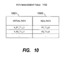
- the outline of the path switching function of the path management program 1162 is as follows.
- a virtual path 10001 virtual path information provided by the path management program 1162 to the application 1161 is set.
- a real path 10002 real path information for access to the logical storage area to correspond to the virtual path indicated by the virtual path 10001 is set.
- the path management program 1162 provides the CLI.
- the administrator can issue a command such as "setPath v_path V_P1_T1_L1 -path P1_T1_L1".
- This command is an instruction to "set a path with a port ID 1, a target ID 1, and a LUN 1 for a virtual path V_P1_T1_L1".
- the virtual path V_P1_T1_L1 is set in the virtual path 10001 and P1_T1_L1 is set in the real path 10002.
- the CPU 1230 calculates the number of remaining rewritable times for each of the physical storage areas 1011 from the obtained maximum writable number and total write number. To be specific, the number of remaining rewritable times is calculated by subtracting the total write number from the maximum writable number. Then, the CPU 1230 compares the number of remaining rewritable times for the physical storage area 1011 corresponding to the primary storage area and that for the physical storage area 1011 corresponding to the secondary storage area with each other (Step 9050).
- the CPU 1230 requests the CPU 1023 executing the duplication management program 1036 to split the pair (in other words, to suspend the duplication) (Step 9100), and then terminates the process.
- the logical storage area "LUN_1” is the primary storage area
- the logical storage area “LUN_2” is the secondary storage area.
- the logical storage areas "LUN_1” and “LUN_2” correspond to the physical storage areas "PDEV_1" and "PDEV_2", respectively.
- the number of remaining rewritable times for the physical storage area "PDEV_1” is 499990000 obtained by subtracting 10000 from 500000000.
- the number of remaining rewritable times for the physical storage area "PDEV_2” is 499999900 obtained by subtracting 100 from 500000000.
- Step 9050 The judgment in Step 9050 described above is executed based on the number of remaining rewritable times calculated by subtracting the total write number from the maximum writable number. As in the case of the first embodiment of this invention, however, as shown in FIG. 7, the judgment may be executed based on the total write number, the number of erasures or the performance.
Landscapes
- Engineering & Computer Science (AREA)
- Theoretical Computer Science (AREA)
- Physics & Mathematics (AREA)
- General Engineering & Computer Science (AREA)
- General Physics & Mathematics (AREA)
- Human Computer Interaction (AREA)
- Quality & Reliability (AREA)
- Information Retrieval, Db Structures And Fs Structures Therefor (AREA)
- Techniques For Improving Reliability Of Storages (AREA)
- Debugging And Monitoring (AREA)
Abstract
Description
- The present application claims priority from
Japanese application JP2006-132597 filed on May 11, 2006 - This invention relates to a computer system, and more particularly, but not exclusively, to a method of managing a storage medium in a computer system including the storage medium having a limited number of rewrites.
- In general information systems, data is regularly backed up. Therefore, if data is lost by a storage system failure, data destruction by a computer virus, an erroneous operation by a user, or the like, the lost data can be recovered.
- As one of backup techniques, a backup method using data duplication has been proposed (for example, see
US 5,051,887 ). According to this method, prior to the execution of backup, data used by an application (hereinafter, referred to as "original data") is duplicated (mirrored) in two storage areas. Then, by suspending the duplication, the backup is executed. As a result, the two storage areas are separated as independent areas. The data in one of the storage areas is handled as the original data, whereas the data in the other storage area is handled as a stored image of the original data at that point of time (hereinafter, referred to as "backup data"). In this manner, high-speed backup is made possible by suspending the duplication. - According to
US 5,051,887 , under the suspension of the duplication of the original data after the backup data is obtained, data update for the original data is allowed. At the same time, the position of the updated data is recorded. The position of the updated data is a position of the storage area in which the data is written, for example, a block address of a block in which the data is written. To delete the backup data, the duplication of the data is restarted. At the same time, based on the record of the position of the updated data, the updated data is copied from the storage area for storing the original data to the storage area for storing the backup data. As a result, the duplication can be restarted at high speed. - The original data and the backup data described above may be stored in a hard disk drive. However, the original data and the backup data may also be stored in other types of non-volatile storage mediums. One of the other types of non-volatile storage mediums is, for example, a flash memory. The flash memory is data-rewritable. However, it is known that the characteristics of the flash memory are degraded by data rewrite. Therefore, when the flash memory is used as the storage medium, the execution of the number of writes exceeding a predetermined upper limit is not allowed to prevent the occurrence of a failure such as a data loss to ensure predetermined reliability and performance.
- In order to prevent write processes from being concentrated in a partial area on the flash memory and to prevent only the partial area from being rapidly deteriorated, a technique of distributing targets of the write process has been disclosed (for example, see
JP 2006-504201 A JP 2006-504201 A - In general backup operation management, backup data is stored in a particular storage area to be retained only for a duration of retention set by an administrator. After the elapse of the duration of retention, new backup data is overwritten in the storage area. By repeating this operation, the backup operation of the original data is continued.
- The application of the technique described in
US 5,051,887 to the operation management realizes the following process. - First, original data is duplicated. To be specific, when data is written from a host computer to a storage area for storing the original data which is one of the two storage areas used for duplication, the written data is copied to the other storage area for storing backup data. Hereinafter, the storage area from which the data is copied is referred to as a primary storage area, whereas the storage area to which the data is copied is referred to as a secondary storage area.
- Thereafter, upon execution of backup, the duplication is suspended. To be specific, data copy from the primary storage area to the secondary storage area is suspended. Even if the data in the primary storage area is updated under suspension of the duplication, the update is not reflected on the secondary storage area. As a result, the data in the secondary storage area is obtained as backup data at the point of suspension of the duplication.
- Thereafter, the duplication is suspended for a duration of retention set by an administrator. When the original data is updated during the retention, the position of update is recorded.
- Thereafter, after elapse of the duration of retention, the duplication is restarted. At the restart of the duplication, the updated data is copied from the primary storage area to the secondary storage area based on the record of the updated position. As a result, the data in the primary storage area and that in the secondary storage area become identical with each other.
- Thereafter, the duplication is suspended again to obtain new backup data.
- In a case where the data at the same position is updated a plurality of times under suspension of the duplication and then the duplication is restarted, only the latest updated data is copied from the primary storage area to the secondary storage area. Therefore, a total number of writes for the secondary storage area is always equal to or less than that for the primary storage area. Then, with the elapse of operation time, a difference in total number of writes between the two storage areas becomes larger.
- Even in a case where the duplication is maintained, when a plurality of data write requests for the same position in the primary storage area are successively issued, only the last written data of all the data is sometimes copied to the secondary storage area. Even in this case, the total number of writes for the secondary storage area is equal to or less than that for the primary storage area.
- The increasing difference in number of writes between the primary storage area and the secondary storage area is generated even if the technique described in
JP 2006-504201 A JP 2006-504201 A - In a case where a storage medium having a limited number of writes such as a flash memory is used as the storage area for storing data, the lifetime of the primary storage area is shorter than that of the secondary storage area. Alternatively, in a case where a storage medium whose I/O performance or the like deteriorates according to the total number of writes such as a flash memory is used as the storage area, the performance of the primary storage area is deteriorated earlier than that of the secondary storage area. Therefore, the storage medium for the primary storage area is required to be frequently replaced. As a result, maintenance cost for backup operation management increases.
- According to a representative embodiment of this invention, there is provided a storage system coupled to a host computer through a network, characterized in that the storage system includes: a plurality of physical storage areas for storing data written by the host computer; and a controller for controlling writing and reading of data to and from the physical storage area, and in that: the plurality of physical storage areas include at least a first physical storage area and a second physical storage area; the controller compares a number of remaining rewritable times for the first physical storage area and a number of remaining rewritable times for the second physical storage area when the same data as data in the first physical storage area is stored in the second physical storage area; and when it is judged that the number of remaining rewritable times for the first physical storage area is less than the number of remaining rewritable times for the second physical storage area, the controller writes the data written by the host computer to the second physical storage area and copies the data written in the second physical storage area to the first physical storage area.
- According to an embodiment of this invention, in a computer system in which backup is executed by using data duplication, a total number of writes for a storage area for storing operation data and that for a storage area for storing backup data are equalized. As a result, an interval between replacements of a storage medium is increased to reduce maintenance cost for backup operation management.
-
- FIG. 1 is a block diagram showing a configuration of a computer system according to a first embodiment of this invention.
- FIG. 2 is an explanatory diagram of a logical-physical mapping table according to the first embodiment of this invention.
- FIG. 3 is an explanatory diagram of a pair definition table according to the first embodiment of this invention.
- FIG. 4 is an explanatory diagram of a differential bit map according to the first embodiment of this invention.
- FIG. 5 is an explanatory diagram of a total write number management table according to the first embodiment of this invention.
- FIG. 6 is a flowchart of a write process executed by a CPU which executes a total write number management program according to the first embodiment of this invention.
- FIG. 7 is a flowchart of a duplication restart process executed by the CPU which executes a duplication management program according to the first embodiment of this invention.
- FIG. 8 is a block diagram showing a configuration of a host computer according to a second embodiment of this invention.
- FIG. 9 is a flowchart of a backup process executed by the CPU which executes a backup management program according to the second embodiment of this invention.
- FIG. 10 is an explanatory diagram of a path management table according to the second embodiment of this invention.
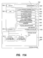
- FIG. 11A is a block diagram showing a configuration of a storage system which includes one flash memory as one physical storage area according to the first embodiment of this invention.
- FIG. 11B is a block diagram showing a configuration of the storage system which includes at least one flash memory and a control device as one physical storage area according to the first embodiment of this invention.
- Hereinafter, a computer system and a storage system according to embodiments of this invention, and a backup management method in the computer system and the storage system will be described with reference to the accompanying drawings. The following description does not intend to limit this invention.
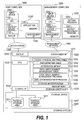
- FIG. 1 is a block diagram showing a configuration of a computer system according to the first embodiment of this invention.
- The computer system according to the first embodiment includes a
storage system 1000, ahost computer 1100, amanagement computer 1200, adata network 1300, and amanagement network 1400. - The
storage system 1000 and thehost computer 1100 are connected to each other through thedata network 1300. In this embodiment, thedata network 1300 is a storage area network (SAN). However, thedata network 1300 may be an IP network or any other types of data communication networks. - The
storage system 1000, thehost computer 1100, and themanagement computer 1200 are connected to each other through themanagement network 1400. In this embodiment, themanagement network 1400 is an IP network. However, themanagement network 1400 may be a SAN or any other types of data communication networks. Alternatively, thedata network 1300 and themanagement network 1400 may be the same network, and thehost computer 1100 and themanagement computer 1200 may be the same computer. - For convenience of the description, FIG. 1 shows only one
storage system 1000, onehost computer 1100, and onemanagement computer 1200. However, this invention is also applicable to a computer system including a larger number of thestorage systems 1000, thehost computers 1100, and themanagement computers 1200. - The
storage system 1000 includes astorage device 1010 which stores data and astorage controller 1020 which controls thestorage system 1000. - The
storage device 1010 includes two or morephysical storage areas 1011. Each of thephysical storage areas 1011 is a physical storage area having a limited number of writes, such as a flash memory. Thephysical storage area 1011 may have a function of equalizing a total write number for each write position in each of thephysical storage areas 1011. Alternatively, each of thephysical storage areas 1011 may be a physical storage area including at least one storage medium and a control device having a function of equalizing a total write number for each write position between the storage mediums. - Hereinafter, this embodiment will be described taking a case where each of the
physical storage areas 1011 is a flash memory as an example. However, each of thephysical storage areas 1011 may be any storage device as long as the number of writes is limited. A flash memory or a phase-change optical disk device can be given as an example. However, this invention is also applicable to a magnetic disk device, an optical disk device, a magnetic tape device, a semiconductor memory device, or other types of storage devices, each of which has a limited number of writes. Examples of a configuration of the storage system when each of thephysical storage areas 1011 is a flash memory will be described in detail below with reference to FIGS. 11A and 11B. - In the
storage system 1000, thephysical storage area 1011 is mapped to (associated with) a logical storage area. Thehost computer 1100 issues I/O instruction to the logical storage area. Various functions of thestorage system 1000 such as remote copy are executed according to an attribute given to the logical storage area. - The
storage controller 1020 includes a management interface (I/F) 1021, a data I/F 1022, aCPU 1023, a storage I/F 1024, and amain memory 1025. - The
CPU 1023 is a processor which executes programs stored in themain memory 1025. - The
main memory 1025 stores a logical-physical mapping table 1031, a pair definition table 1032, adifferential bit map 1033, a total write number management table 1034, a total writenumber management program 1035, aduplication management program 1036, and astorage microprogram 1037. - The
duplication management program 1036 is a program which controls backup using data duplication corresponding to the related art. To be specific, theduplication management program 1036 executes a process which synchronizes data stored in a primary storage area and data stored in a secondary storage area with each other to start the duplication, a process which suspends the duplication, and a process which copies an updated part of the original data to the secondary storage area to restart the duplication. - In this case, the primary storage area is the
physical storage area 1011 corresponding to a copy source of the data or a logical storage area corresponding to the physical storage area 1011 (described below) when the data is duplicated. The primary storage area stores the original data. The secondary storage area is thephysical storage area 1011 corresponding to a copy destination of the data or a logical storage area corresponding to thephysical storage area 1011 when the data is duplicated. The data stored in the secondary storage area is handled as backup data of the original data. - To be specific, the
host computer 1100 issues a data write request (Write instruction) to the primary logical storage area. Thestorage microprogram 1037 writes requested data to the physical storage area corresponding to the primary logical storage area corresponding to a request target according to the write request received from thehost computer 1100. Furthermore, in a case where the duplication is not suspended, thestorage microprogram 1037 copies the data written in the physical storage area corresponding to the primary logical storage area to the physical storage area corresponding to the secondary logical storage area. - In this embodiment, a new process is added to the process which restarts the duplication. The details of the new process will be described below shown in FIG. 7. Hereinafter, a pair of the primary storage area and the secondary storage area is simply referred to as a "pair". Moreover, the synchronization between the primary storage area and the secondary storage area to start or restart the duplication is referred to as "synchronization of the pair". To be specific, as a result of synchronization of the pair, the data stored in the secondary storage area becomes identical with that stored in the primary storage area. The suspension of the duplication for obtaining the backup data is referred to as "split of the pair".
- The total write
number management program 1035 is a program which manages the number of writes, to the physical storage area, (indirectly) generated by the write instruction issued from thehost computer 1100 or a data copy instruction issued from theCPU 1023 which executes the duplication management program. The details of the process will be described below shown in FIG. 6. - The
storage microprogram 1037 executes the input and output (write or read) of the data for thephysical storage areas 1011 in response to a request from thehost computer 1100. Furthermore, thestorage microprogram 1037 executes the setting and the provision of control information in thestorage system 1000 and the like in response to a request from themanagement computer 1200. - The details of each table will be described below with reference to FIGS. 2 to 5.
- The data I/
F 1022 is an interface connected to thedata network 1300 and includes at least one communication port (not shown). Thestorage controller 1020 transmits and receives data and a control instruction to/from thehost computer 1100 via the communication port. - The management I/
F 1021 is an interface connected to themanagement network 1400. Thestorage controller 1020 transmits and receives data and a control instruction to/from thehost computer 1100 and themanagement computer 1200 via the management I/F 1021. - The storage I/
F 1025 is an interface connected to thestorage device 1010, and transmits and receives data and a control instruction. - The
host computer 1100 includes a data I/F 1110, adisplay device 1120, aCPU 1130, aninput device 1140, a management I/F 1150, and amemory 1160. - The data I/
F 1110 is an interface connected to thedata network 1300, and includes at least one communication port (not shown). Thehost computer 1100 transmits and receives data and a control instruction to/from thestorage system 1000 via the communication port. - The management I/
F 1150 is an interface connected to themanagement network 1400. Thehost computer 1100 transmits and receives data and a control instruction to/from themanagement computer 1200 and thestorage system 1000 via the management I/F 1150 for system management. - The
display device 1120 is, for example, a screen display device such as a CRT. - The
input device 1140 is, for example, a keyboard or a mouse. - The
CPU 1130 is a processor which executes a program stored in thememory 1160. - The
memory 1160 stores at least anapplication 1161. - The
application 1161 is an application of a database management system (DBMS), a file system, or the like, which uses the physical storage area identified by a logical identifier. - For convenience of the description, FIG. 1 shows only one
application 1161. However, a plurality of applications may be stored in thememory 1160. - The
management computer 1200 includes a management I/F 1210, adisplay device 1220, aCPU 1230, aninput device 1240, and amemory 1250. - The management I/
F 1210 transmits and receives data and a control instruction to/from thehost computer 1100 and thestorage system 1000 for system management. - The
display device 1220 is, for example, a screen display device such as a CRT. - The
input device 1240 is, for example, a keyboard or a mouse. - The
memory 1250 stores at least abackup management program 1251 and asetting program 1252. - The
CPU 1230 executes various programs stored in thememory 1250 to realize each of the functions. - The
setting program 1252 is a program for setting information in various tables stored in themain memory 1025. Thesetting program 1252 includes a process for communicating with theCPU 1023 which executes thestorage microprogram 1037 to set the information. For establishment of the communication, an IP address of the management I/F 1021 is used. In this embodiment, themanagement computer 1200 has already obtained the IP address. Hereinafter, for communication with theCPU 1023, in a case where theCPU 1230 executes various programs, the communication is established as in the above-mentioned case. Therefore, the description for the establishment of communication is omitted in the following description. - The
setting program 1252 provides a command line interface (CLI) or the like as an interface to allow a storage administrator or the other programs to execute thesetting program 1252. - The
backup program 1251 is a program for communicating with theCPU 1023 which executes thestorage microprogram 1037 according to a backup schedule set by the storage administrator to instruct the synchronization or the split of the pair. - FIGS. 11A and 11B are block diagrams, each showing a configuration of the
storage system 1000 including flash memories as thephysical storage areas 1011 according to the first embodiment of this invention. - In an example shown in FIG. 11A, one
physical storage area 1011 is composed of one flash memory. - In an example shown in FIG. 11B, one
physical storage area 1011 includes at least one flash memory (FM) and a controller having the function of equalizing the total write numbers for each write position between the flash memories. - FIGS. 2 to 5 show tables stored in the
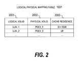
main memory 1025. - FIG. 2 is an explanatory diagram of the logical-physical mapping table 1031 according to the first embodiment.
- In the logical-physical mapping table 1031, mapping information which associates the logical storage area and the
physical storage area 1011 with each other is set. In alogical VOLID 2001, an identifier of a logical storage area is set. In aphysical VOLID 2002, an identifier of thephysical storage area 1011 corresponding to the logical storage area is set. - The
setting program 1252 provides the CLI to set the above-mentioned two values. For example, by using the CLI, the administrator can issue a command such as "createVol -from PDEV_1". This command is an instruction which means "create a logical storage area from the physical storage area PDEV_1". The PDEV_1 is set in thephysical VOLID 2002. In thelogical VOLID 2001, an identifier that theCPU 1023 executing thestorage microprogram 1037 can uniquely identify in the storage system is set. - For example, when a logical storage area LUN_1 corresponding to the physical storage area PDEV_1 is created as the result of execution of the above-mentioned command, "LUN_1" is set in the
logical VOLID 2001 to correspond to the value "PDEV_1" of thephysical VOLID 2002. - In the logical-physical mapping table 1031, information indicating an attribute given to the logical storage area may also be set. FIG. 2 shows a
cache residence 2003 as an example of the attribute given to the logical storage area. In thecache residence 2003, for example, information indicating whether or not to make the data stored in the logical storage area to be resident in a cache memory (not shown) is set. When only the data stored in a part of the logical storage area is made to be resident in the cache memory (not shown), information specifying the part of the logical storage area is set in thecache residence 2003. - In the example shown in FIG. 2, as the
cache residence 2003 corresponding to the value "LUN_1" of thelogical VOLID 2001, "0 to 1024" is set. This value indicates that data stored ataddresses 0 to 1024 in the logical storage area LUN_1 is made to be resident in the cache memory. On the other hand, as thecache residence 2003 corresponding to the value "LUN_2" of thelogical VOLID 2001, "off' is set. This indicates that data stored in the logical storage area LUN_2 is not °made to be resident in the cache memory. - The
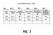
setting program 1252 provides the CLI to set thecache residence 2003. For example, by using the CLI, the administrator can issue a command such as "useCache -vol LUN_1 -from 0 -to 1024". This command corresponds to an instruction which means "make data ataddresses 0 to 1024 in the logical storage area LUN_1 to be resident in the cache memory". Accordingly, the value "0 to 1024" of thecache residence 2003 corresponding to the "LUN_1" in FIG. 2 is set. - FIG. 3 is an explanatory diagram of the pair definition table 1032 according to the first embodiment of this invention.
- In the pair definition table 1032, management information for controlling the backup using the data duplication is set.
- In a pair name 3001, an identifier of a pair is set.
- In a
primary VOLID 3002, an identifier of a logical storage area set as the primary storage area is set. - In a primary
differential BM 3003, information for identifying a primary differential bitmap is set. The primary differential bitmap shown in FIG. 4 is a bitmap for managing the position of write when the write occurs in the primary storage area under suspension of the duplication. - In a secondary VOLID 3004, an identifier of a logical storage area set as the secondary storage area is set.
- In a secondary
differential BM 3005, information for identifying a secondary differential bitmap is set. The secondary differential bitmap shown in FIG. 4 is a bitmap managing the position of write when the write occurs in the secondary storage area under suspension of the duplication. - In a primary-
secondary swapping allowance 3006, information indicating whether or not to allow the physical storage areas to be swapped is set. The swapping of the physical storage areas is, for example, a process of newly associating thephysical storage area 1011 currently associated with the primary storage area, with the secondary storage area, and newly associating thephysical storage area 1011 currently associated with the secondary storage area, with the primary storage area, when the number of remaining rewritable times for the primary storage area is less than that for the secondary storage area. When the swapping is allowed, "true" is set in the primary-secondary swapping allowance 3006. When the swapping is not allowed, "false" is set in the primary-secondary swapping allowance 3006. - The
setting program 1252 provides the CLI to set the above values. For example, by using the CLI, the storage administrator can issue a command such as "createPair -p LUN_1 -s LUN_2 -swap true pair1". This command is an instruction to "define a pair "pair1" with the logical storage area LUN_1 as the primary storage area and the logical storage area LUN_2 as the secondary storage area, and allow swapping according to the number of remaining rewritable times". As the result of execution of the instruction, values indicated in the first record in FIG. 3 are set in the pair definition table 1032. To be specific, "pair1" is set in the pair name 3001, "LUN_1" in theprimary VOLID 3002, "LUN_2" in the secondary VOLID 3004, and "true" in the primary-secondary swapping allowance 3006. - Furthermore, for the pair definition, two
differential bitmaps 1033 for the primary storage area and the secondary storage area are created. In an example of the first record in FIG. 3, an identifier "BM_1" of a differential bitmap for the primary storage area is set in the primarydifferential BM 3003, whereas an identifier "BM_2" of a differential bitmap for the secondary storage area is set in the secondarydifferential BM 3005. - FIG. 4 is an explanatory diagram of the
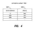
differential bitmap 1033 according to the first embodiment of this invention. - The
differential bitmap 1033 is information for managing the position at which write occurs when the write occurs in each of the logical storage areas in the state where the pair is split (in other words, under suspension of the duplication). In thedifferential bitmap 1033 according to this embodiment, the occurrence of write is managed for each block (one block = 1024 bytes). However, the occurrence of write may be managed in the other units. In ablock address 4001, an address of a block to be managed is set. - In an
update 4002, information indicating the occurrence/non-occurrence of write is set. To be specific, when write occurs, "true" is set. When write does not occur, "false" is set. - Upon definition of a pair, the
differential bitmap 1033 according to this embodiment is created to correspond to each of the primary storage area and the secondary storage area of the pair. - In the
block address 4001, a head address of a block to be managed for the occurrence/non-occurrence of write is set in defining the pair. - A value of the
update 4002 is referred to for the execution of synchronization of the pair. Accordingly, the data stored in the block having "true" as the value of theupdate 4002 is copied from the primary storage area to the secondary storage area. After the completion of the copy, "false" is set in theupdate 4002. When the write in the storage area occurs in the state where the pair is split, "true" is set as the value of theupdate 4002 corresponding to a write target block. - In the example shown in FIG. 4, at least "0", "1024", and "2048" are set as the block addresses 4001. Set as the
updates 4002 corresponding to these values are "false", "true", and "false", respectively. The values in theupdate 4002 indicate that write does not occur in a 1024-byte block starting from the block address "0" and in a 1024-byte block starting from the block address "2048", whereas write occurs in a 1024-byte block starting from the block address "1024". - FIG. 5 is an explanatory diagram of the total write number management table 1034 according to the first embodiment of this invention.
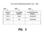
- In the total write number management table 1034, information for managing a total number of writes executed for the
physical storage area 1011 is set. In aphysical VOLID 5001, an identifier of thephysical storage area 1011 is set. In atotal write number 5002, the number of writes which have already been executed for thephysical storage area 1011 indicated in thephysical VOLID 5001 is set. In amaximum writable number 5003, the maximum value of the number of write processes executable for thephysical storage area 1011 indicated in thephysical VOLID 5001 is set. - The
physical VOLID 5001 is set by the assignment of an identifier for uniquely identifying thephysical storage area 1011, which is executed by theCPU 1023 executing thestorage microprogram 1037 upon installation of thephysical storage area 1011. - In the
maximum writable number 5003, information input by the system administrator or information provided by thephysical storage area 1011 is set upon installation of thephysical storage area 1011. - For example, the system administrator may execute the
setting program 1252 of themanagement computer 1200 to input themaximum writable number 5003 to thestorage controller 1020. Thestorage controller 1020 sets the input value in themaximum writable number 5003. - Upon installation of the
physical storage area 1011, "0" is set in thetotal write number 5002. Then, each time write in thephysical storage area 1011 occurs in response to a write instruction from thehost computer 1100 or a data copy instruction from theCPU 1023 which executes theduplication management program 1036, the value in thetotal write number 5002 is incremented by the total writenumber management program 1035. - In this embodiment, the
maximum writable number 5003 corresponds to the lifetime of thephysical storage area 1011. In another embodiment of this invention, however, when thephysical storage area 1011 whose performance deteriorates depending on the number of writes is used, a value indicating the largest number of writes with which performance deterioration is allowed (in other words, the maximum number of writes causing allowable performance deterioration) may be set in themaximum writable number 5003. - In this embodiment, the total write number management table 1034 is stored in the
main memory 1025 within thestorage controller 1020. However, the total write number management table 1034 may be retained in any part of the computer system. For example, thestorage device 1010 or themanagement computer 1200 may retain the total write number management table 1034. - Next, an operation of this first embodiment will be described.
- FIG. 6 is a flowchart of a write process executed by the
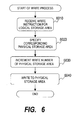
CPU 1023 which executes the total writenumber management program 1035 according to the first embodiment of this invention. - To be more specific, FIG. 6 shows a process executed by the
CPU 1023 which executes the total writenumber management program 1035 when theCPU 1023 receives the write instruction. The write instruction may be issued by thehost computer 1100 with respect to the logical storage area or may be generated by the data copy executed for the synchronization of a pair by theCPU 1023 executing theduplication management program 1036 with respect to the logical storage area. - First, the
CPU 1023 receives the write instruction for the logical storage area (Step 6010). The write instruction contains an identifier of a write destination logical storage area and a write destination block address. - Next, the
CPU 1023 refers to the logical-physical mapping table 1031 to obtain an identifier of thephysical storage area 1011 corresponding to the logical storage area (Step 6020). - Next, the
CPU 1023 refers to the total write number management table 1034 to increment thetotal write number 5002 of thephysical storage area 1011 to which the identifier obtained inStep 6020 is assigned (Step 6030). - In the final step, the
CPU 1023 writes data to thephysical storage area 1011 to which the identifier obtained inStep 6020 is assigned (Step 6040). At this time, the write destination block address is the block address contained in the write instruction received inStep 6010. - The above described is the operation of the
CPU 1023 which executes the total writenumber management program 1035 upon reception of the write instruction for the logical storage area. - FIG. 7 is a flowchart of a duplication restart process executed by the
CPU 1023 which executes theduplication management program 1036 according to the first embodiment of this invention. - To be specific, FIG. 7 shows a process executed by the
CPU 1023 which executes theduplication management program 1036 upon reception of an instruction of restarting the duplication from thebackup management program 1251. - First, the
CPU 1023 receives an instruction of restarting the duplication of the original data (Step 7010). The instruction contains a pair name to be synchronized. - Next, the
CPU 1023 copies differential data (Step 7020). To be specific, theCPU 1023 refers to the pair definition table 1032 to specify thedifferential bitmap 1033 corresponding to the pair to be synchronized. At this time, two differential bitmaps respectively corresponding to the primary storage area and the secondary storage area are specified. When a block having "true" as the value of theupdate 4002 exists in any of the two differential bitmaps, theCPU 1023 copies data stored in the corresponding block from the primary storage area to the secondary storage area. - When the
CPU 1023 judges that all the addresses in the differential bitmaps have been checked, theCPU 1023 recognizes that the data stored in the primary storage area and that stored in the secondary storage area are now identical with each other. Then, theCPU 1023 judges whether or not swapping of the primary storage area and the secondary storage area is required (seeSteps 7030 and 7040). - To be specific, the
CPU 1023 refers to the total write number management table 1034 to obtain thetotal write number 5002 and themaximum writable number 5003 corresponding to thephysical VOLID 5001 of thephysical storage area 1011 corresponding to each of the logical storage areas (Step 7030). - Next, the
CPU 1023 calculates the number of remaining rewritable times for each of thephysical storage areas 1011 from the obtained maximum writable number and total write number. To be specific, the number of remaining rewritable times is calculated by subtracting the total write number from the maximum writable number. Then, theCPU 1023 compares the number of remaining rewritable times for thephysical storage area 1011 corresponding to the primary storage area and the number of remaining rewritable times for thephysical storage area 1011 corresponding to the secondary storage area (Step 7040). - When it is judged in
Step 7040 that the number of remaining rewritable times for the primary storage area is larger, it is desirable to continue using the storage area currently set as the primary storage area as the primary storage area to equalize the numbers of writes. Therefore, theCPU 1023 judges that the swapping of the primary storage area and the secondary storage area is not required, terminating the process without executing the swapping. - On the other hand, when it is judged in
Step 7040 that the number of remaining rewritable times for the secondary storage area is larger, it is desirable to swap the primary storage area and the secondary storage area to equalize the numbers of writes. In this case, theCPU 1023 judges that the swapping of the primary storage area and the secondary storage area is required. Then, theCPU 1023 refers to the pair definition table 1032 to judge whether or not the swapping of the physical storage area mapped to the primary storage area and the physical storage area mapped to the secondary storage area is allowed (Step 7050). - When it is judged in
Step 7050 that the swapping is not allowed, theCPU 1023 terminates the process. - On the other hand, when the swapping is allowed, the
CPU 1023 refers to the logical-physical mapping table 103 to swap the physical VOLID of the primary storage area and the physical VOLID of the secondary storage area (Step 7060). Then, theCPU 1023 terminates the process. - The above-mentioned duplication restart process may be executed at the time when the number of write processes executed after the execution of the previous swapping of the primary storage area and the secondary storage area reaches a predetermined number.
- A specific example of the write process will now be described with reference to FIGS. 2 to 5. In the example shown in FIG. 3, in the pair "pair1", the logical storage area "LUN_1" is the primary storage area, whereas the logical storage area "LUN_2" is the secondary storage area. In the example shown in FIG. 2, the logical storage areas "LUN_1" and "LUN_2" correspond to the physical storage areas "PDEV_1" and "PDEV_2", respectively. In the example shown in FIG. 5, the number of remaining rewritable times for the physical storage area "PDEV_1" is 499990000 obtained by subtracting 10000 from 500000000. On the other hand, the number of remaining rewritable times for the physical storage area "PDEV_2" is 499999900 obtained by subtracting 100 from 500000000.
- In this case, it is judged in
Step 7040 shown in FIG. 7 that the number of remaining rewritable times for the secondary storage area is larger. As shown in FIG. 3, because the swapping of the primary storage area and the secondary storage area of the pair "pair1" is allowed, the physical VOLID of the primary storage area and the physical VOLID of the secondary storage area are swapped inStep 7060. To be specific, in the logical-physical mapping table 1031 shown in FIG. 2, the value of thephysical VOLID 2002 corresponding to the value "LUN_1" of thelogical VOLID 2001 is updated to "PDEV_2". On the other hand, the value of thephysical VOLID 2002 corresponding to the value "LUN_2" of thelogical VOLID 2001 is updated to "PDEV_1". - Accordingly, for example, when the
host computer 1100 issues a request of writing data in the logical storage area "LUN_1", thestorage microprogram 1037 writes the data to the physical storage area "PDEV_2". Furthermore, thestorage microprogram 1037 copies the data written in the physical storage area "PDEV_2" to the physical storage area "PDEV_1" corresponding to the logical storage area "LUN_2". In this manner, the primaryphysical storage area 1011 and the secondaryphysical storage area 1011 are swapped to equalize the numbers of writes. - As illustrated in FIG. 2, the attribute such as the
cache residence 2003 is assigned to the logical storage area. Therefore, as the result of swapping of the primaryphysical storage area 1011 and the secondaryphysical storage area 1011 inStep 7040, the attributes of the respectivephysical storage areas 1011 are also swapped. - For example, even if the physical storage area corresponding to the logical storage area "LUN_1" is changed from "PDEV_1" to "PDEV_2" as described above, the value of the
cache residence 2003 which is the attribute corresponding to the logical storage area "LUN_1" still remains as "0 to 1024". Similarly, even if the physical storage area corresponding to the logical storage area "LUN_2" is changed from "PDEV_2" to "PDEV_1", the value of thecache residence 2003 which is the attribute corresponding to the logical storage area "LUN_2" still remains as "off'. Accordingly, the value of thecache residence 2003 corresponding to the physical storage area "PDEV_1" is changed from "0 to 1024" to "off" and the value of thecache residence 2003 corresponding to the physical storage area "PDEV_2" is changed from "off" to "0 to 1024". - When it is judged in
Step 7040 that the number of remaining rewritable times for the primary storage area is the same as that for the secondary storage area, the swapping of the primaryphysical storage area 1011 and the secondaryphysical storage area 1011 may be executed but is not required to be executed. In this embodiment, when the numbers of remaining rewritable times are the same for the primaryphysical storage area 1011 and the secondaryphysical storage area 1011, the swapping of the primaryphysical storage area 1011 and the secondaryphysical storage area 1011 is not executed. - In the above description for FIG. 7, the number of remaining rewritable times is calculated by subtracting the total write number from the maximum writable number to judge whether or not to execute the swapping of the physical storage areas 1011 (Step 7040). However, this invention can be implemented whichever method is used to calculate or estimate the number of remaining rewritable time.
- For example, when the primary and secondary
physical storage areas 1011 are composed of recording media of the same type, the maximumwritable numbers 5003 for the primary and secondaryphysical storage areas 1011 are estimated to be the same. Therefore, theCPU 1023 may compare thetotal write number 5002 for the primary storage area and that for the secondary storage area with each other inStep 7040 to judge that the number of remaining rewritable times is larger for thephysical storage area 1011 having a smaller total number of writes. In other words, the comparison between thetotal write number 5002 for the primary storage area and that for the secondary storage area inStep 7040 corresponds to the comparison between the number of remaining rewritable times for the primary storage area and that for the secondary storage area. - Alternatively, the number of remaining rewritable times may be calculated based on the number of erasures in place of the number of writes. Prior to the write of data in the flash memory, a process of erasing data already written in a write destination area of the data is executed. The lifetime of the flash memory depends on the number of erasure processes.
- Therefore, for example, a total number of erasures may be set in place of the
total write number 5002 and a maximum number of erasable times may be set in place of themaximum writable number 5003 in the total write number management table (FIG. 5). The total number of erasures corresponds to the number of actually executed erasure processes, whereas the maximum number of erasable times corresponds to the maximum value of the number of executable erasure processes. In this case, inStep 7040, it is judged that thephysical storage area 1011 having a larger value obtained by subtracting the total number of erasures from the maximum number of erasable times has a larger number of remaining rewritable times. In other words, the comparison between the numbers of remaining erasable times inStep 7040 corresponds to the comparison between the number of remaining rewritable times for the primary storage area and that for the secondary storage area. - Alternatively, the judgment in
Step 7040 may be executed depending only on the total number of erasures. When the primary and secondaryphysical storage areas 1011 are composed of recording media of the same type, the maximum number of erasable times is estimated to be the same for both thephysical storage areas 1011. Therefore, theCPU 1023 may compare inStep 7040 the total number of erasures for the primaryphysical storage area 1011 and that for the secondaryphysical storage area 1011 with each other to judge that the number of remaining rewritable times is larger for thephysical storage area 1011 having a smaller total number of erasures. In other words, the comparison inStep 7040 between the total number of erasures for the primary physical storage area and that for the secondary physical storage area with each other corresponds to the comparison between the number of remaining rewritable times for the primary physical storage area and that for the secondary physical storage area. - Further alternatively, the performance of the primary
physical storage area 1011 and that of the secondaryphysical storage area 1011 may be compared with each other to execute the judgment inStep 7040 based on the result of comparison. The performance of thephysical storage area 1011 is, for example, a write performance for writing data in thephysical storage area 1011. The flash memory has a characteristic that the write performance becomes lower depending on the number of executed data erasures. Therefore, theCPU 1023 may monitor the write performance to compare inStep 7040 the write performance of the primaryphysical storage area 1011 and that of the secondaryphysical storage area 1011 with each other. - In this case, in
Step 7040, it is judged that the number of remaining rewritable times is larger of thephysical storage area 1011 having higher write performance. In other words, the comparison inStep 7040 between the performance of the primaryphysical storage area 1011 and that of the secondaryphysical storage area 1011 corresponds to the comparison between the number of remaining rewritable times of the primaryphysical storage area 1011 and that of the secondaryphysical storage area 1011. A target to be compared inStep 7040 may be any performance other than the write performance. - It is sometimes difficult to maintain the state where the data stored in two storage areas are synchronized with each other even while the duplication is being executed, which is because of the execution of writes in the primary storage area and the secondary storage area in an asynchronous manner. In this case, as another embodiment, a step (not shown) of suspending the write instruction from the
host computer 1100 is added immediately afterStep 7010. Furthermore, a step (not shown) of canceling the suspension of the write instruction from thehost computer 1100 is added immediately before the termination of the duplication restart process. In this manner, this invention can be implemented. - The first embodiment of this invention has been described above. According to the first embodiment, the total write number for the storage area for storing the original data and the total write number for the storage area for storing the backup data are equalized to increase an interval between the replacements of a recording medium used for backup using the data duplication. Accordingly, the maintenance cost for backup operation management can be reduced.
- Next, a second embodiment of this invention will be described. In the second embodiment, as in the first embodiment, the number of remaining rewritable times for the physical storage area corresponding to the primary storage area and that for the physical storage area corresponding to the secondary storage area are compared with each other. Then, when the number of remaining rewritable times for the physical storage area corresponding to the primary storage area is smaller than that for the physical storage area corresponding to the secondary storage area, the physical storage areas are swapped. However, the second embodiment differs from the first embodiment in that the
duplication management program 1036 stored in thestorage system 1000 does not have the function of executing the comparison and the swapping described above. The second embodiment exemplifies that thebackup management program 1251 stored in themanagement computer 1200 provides the function of the comparison and the swapping described above to make this invention applicable. - FIG. 8 is a block diagram showing a configuration of the
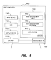
host computer 1100 according to the second embodiment of this invention. - The configuration of the computer system according to the second embodiment is the same as that according to the first embodiment except for the
host computer 1100. Therefore, hereinafter, only the configuration of thehost computer 1100 will be described. - In this embodiment, in the
memory 1160 of thehost computer 1100, apath management program 1162 and a path management table 1163 are stored in addition to theapplication 1161. - The
path management program 1162 is a program for managing a path to the logical storage area, which is used by thehost computer 1100. As in the case of general path management software, thepath management program 1162 has a function of switching paths and a function of suspending the I/O instruction from theapplication 1161. Thepath management program 1162 provides the CLI or the like as an interface to allow the administrator or the other programs to execute thepath management program 1162. - The outline of the path switching function of the
path management program 1162 is as follows. - The
CPU 1130 which executes thepath management program 1162 refers to the path management table 1163 to provide a virtual path for theapplication 1161. Then, theCPU 1130 transfers an I/O instruction to the virtual path, which is issued by theapplication 1161, to a real path associated with the virtual path. By changing the association between the virtual path and the real path, the path can be changed without affecting theapplication 1161. - FIG. 10 is an explanatory diagram of the path management table 1163 according to the second embodiment of this invention.
- The path management table 1163 is a table for mapping a real path to the logical storage area and a virtual path used by the
application 1161. TheCPU 1130, which executes thepath management program 1162, sets a value in the path management table 1163. The virtual path used by theapplication 1161 is designated when theapplication 1161 issues the I/O instruction. - In a
virtual path 10001, virtual path information provided by thepath management program 1162 to theapplication 1161 is set. In areal path 10002, real path information for access to the logical storage area to correspond to the virtual path indicated by thevirtual path 10001 is set. In order to set these information, thepath management program 1162 provides the CLI. For example, the administrator can issue a command such as "setPath v_path V_P1_T1_L1 -path P1_T1_L1". This command is an instruction to "set a path with a port ID 1, a target ID 1, and a LUN 1 for a virtual path V_P1_T1_L1". The virtual path V_P1_T1_L1 is set in thevirtual path 10001 and P1_T1_L1 is set in thereal path 10002. - Hereinafter, a process executed in this embodiment, which is different from those in the first embodiment, will be described. The points omitted in the following description are the same as those in the first embodiment.
- First, as shown in FIG. 7, an operation of the
CPU 1023 which executes theduplication management program 1036 according to the second embodiment will be described in comparison with the first embodiment. - The
duplication management program 1036 according to the first embodiment includes the process of comparing the number of remaining rewritable times for thephysical storage area 1011 corresponding to the primary storage area and that for thephysical storage area 1011 corresponding to the secondary storage area (Step 7040), and the process of swapping thephysical storage areas 1011 when the number of remaining rewritable times for thephysical storage area 1011 corresponding to the primary storage area is less than that for thephysical storage area 1011 corresponding to the secondary storage area (Step 7060). - However, the
duplication management program 1036 according to the second embodiment does not include any of the processes of comparison and of swapping described above. In other words, theCPU 1023 which executes theduplication management program 1036 in this embodiment terminates the process after the execution of the process inStep 7020 described in FIG. 7 without executingSteps 7030 to 7060. - Next, an operation of the
CPU 1230, which executes thebackup management program 1251, for obtaining new backup data will be described with reference to FIG. 9. - FIG. 9 is a flowchart of a backup process executed by the
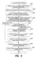
CPU 1230 which executes thebackup management program 1251 according to the second embodiment of this invention. - First, the
CPU 1230 requests theCPU 1023 executing theduplication management program 1036 to synchronize the pair to restart the duplication of the pair at the time of obtaining new backup data (Step 9010). - Next, the
CPU 1230 requests theCPU 1130 executing thepath management program 1162 to suspend the I/O instruction from the application 1161 (Step 9020). - Next, the
CPU 1230 waits until the data in the primary storage area and the data in the secondary storage area are synchronized with each other (Step 9030). In this step, theCPU 1230 regularly makes a query to theCPU 1023 executing theduplication management program 1036 to verify the synchronization between the data in the primary storage area and that in the secondary storage area. Upon reception of a response indicating that the data have been synchronized from theCPU 1023, theCPU 1230 recognizes that the data stored in the primary storage area and the data stored in the secondary storage area are now identical with each other. Then, theCPU 1230 judges whether or not to swap the primary storage area and the secondary storage area (seeSteps 9040 and 9050). - To be specific, after verification of the synchronization, the
CPU 1230 obtains the total write number for thephysical storage area 1011 corresponding to the primary storage area, the maximum writable number for thephysical storage area 1011, the total write number for thephysical storage area 1011 corresponding to the secondary storage area, and the maximum writable number for thephysical storage area 1011, from theCPU 1023 which executes the total write number management program 1035 (Step 9040). To be specific, theCPU 1023 refers to the total write number management table 1034 to obtain thetotal write number 5002 and themaximum writable number 5003 and to transmit the obtainedtotal write number 5002 and maximumwritable number 5003 to themanagement computer 1200 via the management I/F 1021 and themanagement network 1400. - Next, the
CPU 1230 calculates the number of remaining rewritable times for each of thephysical storage areas 1011 from the obtained maximum writable number and total write number. To be specific, the number of remaining rewritable times is calculated by subtracting the total write number from the maximum writable number. Then, theCPU 1230 compares the number of remaining rewritable times for thephysical storage area 1011 corresponding to the primary storage area and that for thephysical storage area 1011 corresponding to the secondary storage area with each other (Step 9050). - In
Step 9050, when it is judged that the number of remaining rewritable times for thephysical storage area 1011 corresponding to the primary storage area is equal to or larger than that for thephysical storage area 1011 corresponding to the secondary storage area, theCPU 1230 judges that the primary and secondaryphysical storage areas 1011 are not required to be swapped. In this case, theCPU 1230 requests theCPU 1130 executing thepath management program 1162 to cancel the suspension of the I/O instruction requested in Step 9020 (Step 9090). - Next, the
CPU 1230 requests theCPU 1023 executing theduplication management program 1036 to split the pair (in other words, to suspend the duplication) (Step 9100), and then terminates the process. - On the other hand, in
Step 9050, when it is judged that the number of remaining rewritable times for thephysical storage area 1011 corresponding to the primary storage area is less than that for thephysical storage area 1011 corresponding to the secondary storage area, theCPU 1230 judges that the primary and secondaryphysical storage areas 1011 are required to be swapped. In this case, theCPU 1230 requests theCPU 1130 executing thepath management program 1162 to change a destination of connection of the access path from the primary storage area identified by theprimary VOLID 3002 to the secondary storage area identified by the secondary VOLID 3004 (Step 9060). TheCPU 1130 executing thepath management program 1162, which has received the request, rewrites the value of thereal path 10002 in the path management table 1163 to change the path. - Next, the
CPU 1230 requests theCPU 1023 executing thestorage microprogram 1037 to change the pair definition (Step 9070). To be specific, theCPU 1230 makes a request of swapping the value of theprimary VOLID 3002 and the value of the secondary VOLID 3004 in the pair definition table 1032. - Next, the
CPU 1230 requests theCPU 1023 executing thestorage microprogram 1037 to swap the attribute set in theprimary VOLID 3002 and the attribute set in the secondary VOLID 3004 (Step 9080). - Herein, the attribute is, for example, the
cache residence 2003 shown in FIG. 2. When the frequency of accesses to a part of or all of a certain storage area is high, all the data stored in the corresponding area is copied to a high-speed cache memory (not shown). Accordingly, a large number of accesses are made to the cache memory to increase the process speed. - Since the primary storage area is accessed from the
host computer 1100, the access speed is expected to be increased by copying the data in the primary storage area to the cache memory. However, since the secondary storage area is not accessed from thehost computer 1100, it is normally not required to copy the data in the secondary storage area to the cache memory. However, as the result ofSteps host computer 1100. Therefore, by copying the data in the new primary storage area to the cache memory, the access speed is increased. Therefore, when the attribute indicating the copy of data to the cache memory is set for the primary storage area, predetermined performance or function can be maintained by swapping the attributes respectively set for the primary storage area and the secondary storage area simultaneously with the execution of swapping of the primary storage area and the secondary storage area. - The case where the attribute is the
cache residence 2003 has been described above as an example. However, any other attributes may be set for each of the storage areas. Even in such cases, by swapping the attributes set for the respective areas, predetermined performance or function can be maintained. - Thereafter, the process after
Step 9090 described above is continued. - In normal backup operation, the backup process is executed at predetermined intervals or at backup intervals determined by the administrator. In this embodiment, however, a copy command may be issued when a predetermined period of time has elapsed after the execution of the previous backup process and when the number of writes reaches a predetermined number. As a result, the above-mentioned backup process is executed to swap the primary storage area and the secondary storage area.
- A specific example of the write process will now be described with reference to FIGS. 2 to 5 and 10. In the example shown in FIG. 3, in the pair "pair1", the logical storage area "LUN_1" is the primary storage area, whereas the logical storage area "LUN_2" is the secondary storage area. In the example shown in FIG. 2, the logical storage areas "LUN_1" and "LUN_2" correspond to the physical storage areas "PDEV_1" and "PDEV_2", respectively. In the example shown in FIG. 5, the number of remaining rewritable times for the physical storage area "PDEV_1" is 499990000 obtained by subtracting 10000 from 500000000. On the other hand, the number of remaining rewritable times for the physical storage area "PDEV_2" is 499999900 obtained by subtracting 100 from 500000000.
- Furthermore, in the example shown in FIG. 10, the virtual path "V_P1_T1_L1" and the real path "P1_T1_L1" are associated with each other. In this example, the real path "P1_T1_L1" is a path from the
host computer 1100 to the logical storage area "LUN_1". In this case, when theapplication 1161 issues a write request to the virtual path "V_P1_T1_L1", thepath management program 1162 transfers the write request to the real path "P1_T1_L1". Accordingly, the write to the logical storage area "LUN_1" is executed. The data written in the logical storage area "LUN_1" is actually written in the physical storage area "PDEV_1". - In this case, in
Step 9050 shown in FIG. 9, it is judged that the number of remaining rewritable times for the secondary storage area is larger. Then, inStep 9060, a path switching request is issued. - The
CPU 1130, which has received the path switching request, executes thepath management program 1162 to update the value of thereal path 10002 corresponding to the virtual path "V_P1_T1_L1" in the path management table 1163 from "P1_T1_L1" to "P1_T1_L2". As a result, the real path "P1_T1_L2" is now associated with the virtual path "V_P1_T1_L1". The real path "P1_T1_L2" is a path from thehost computer 1100 to the logical storage area "LUN_2". After that, when theapplication 1161 issues a write request to the virtual path "V_P1_T1_L1" (in other words, a write request to the logical storage area "LUN_1"), thepath management program 1162 transfers the request to the real path "P1_T1_L2". Accordingly, the write to the logical storage area "LUN_2" is executed. The data written in the logical storage area "LUN_2" is actually written in the physical storage area "PDEV_2" by thestorage microprogram 1037. - Next, in
Step 9070 of FIG. 9, a pair definition changing request is issued. TheCPU 1023, which has received the request, executes thestorage microprogram 1037 to swap the "LUN_1" and the "LUN_2 in the pair definition table 1032. Accordingly, the "LUN_2" is set in theprimary VOLID 3002 and the "LUN_1" is set in the secondary VOLID 3004 corresponding to the pair name "pair1". As a result, the logical storage area "LUN_2" serves as the primary storage area, whereas the logical storage area "LUN_1" serves as the secondary storage area. - Accordingly, for example, when the
application 1161 issues a request of writing the data to the logical storage area "LUN_1", the data is actually written to the physical storage area "PDEV_2". When the duplication is not suspended, the data written in the physical storage area "PDEV_2" is copied to the physical storage area "PDEV_1". In this manner, the primary and secondaryphysical storage areas 1011 are swapped to equalize the numbers of writes. - The judgment in
Step 9050 described above is executed based on the number of remaining rewritable times calculated by subtracting the total write number from the maximum writable number. As in the case of the first embodiment of this invention, however, as shown in FIG. 7, the judgment may be executed based on the total write number, the number of erasures or the performance. - The second embodiment has been described above, taking the case where the primary and secondary storage areas are included in the
same storage system 1000 as an example. However, the above-mentioned second embodiment can be implemented even in the case where the computer system includes a plurality of thestorage systems 1000 connected to thedata network 1300, and the primary storage area and the secondary storage area forming a pair are stored in thedifferent storage systems 1000, respectively. - The above described is the description of the second embodiment of this invention. According to the second embodiment, the
management computer 1200 executes the process of comparing the number of remaining rewritable times for thephysical storage area 1011 corresponding to the primary storage area and that for thephysical storage area 1011 corresponding to the secondary storage area with each other. Furthermore, when the former number of remaining rewritable times is smaller than the latter one as a result of the comparison, themanagement computer 1200 executes the process of swapping thephysical storage areas 1011. Accordingly, even when the storage system is not capable of executing the processes of comparison and swapping described above, this invention is applicable. As a result, the total write number for the storage area for storing the original data and the total write number for the storage area for storing the backup data are equalized to increase the interval between the replacements of a storage medium used for backup using the data duplication. As a result, the maintenance cost for backup operation management can be reduced.
Claims (20)
- A storage system coupled to a host computer through a network, comprising:a plurality of physical storage areas for storing data written by the host computer; anda controller for controlling writing and reading of data to and from the physical storage area, wherein:the plurality of physical storage areas include at least a first physical storage area and a second physical storage area;the controller compares a number of remaining rewritable times for the first physical storage area and a number of remaining rewritable times for the second physical storage area when the same data as data in the first physical storage area is stored in the second physical storage area; andwhen it is judged that the number of remaining rewritable times for the first physical storage area is less than the number of remaining rewritable times for the second physical storage area, the controller writes the data written by the host computer to the second physical storage area and copies the data written in the second physical storage area to the first physical storage area.
- The storage system according to Claim 1, wherein:the controller retains a maximum writable number corresponding to a maximum value of the number of write processes executable for each of the physical storage areas and a total write number corresponding to the number of write processes already executed for each of the physical storage areas; andthe controller subtracts the total write number from the maximum writable number to calculate the number of remaining rewritable times.
- The storage system according to Claim 2, wherein:the controller accepts an input of the maximum writable number; andthe controller retains the input maximum writable number.
- The storage system according to Claim 1, wherein:the controller retains a total write number corresponding to the number of write processes already executed for each of the physical storage areas; andthe controller judges that the number of remaining rewritable times for the first physical storage area is less than the number of remaining rewritable times for the second physical storage area when the total write number for the first physical storage area is larger than the total write number for the second physical storage area.
- The storage system according to any one of Claims 1 to 4, wherein the controller swaps an attribute set for the first physical storage area and an attribute set for the second physical storage area when the number of remaining rewritable times for the first physical storage area is less than the number of remaining rewritable times for the second physical storage area.
- The storage system according to any one of Claims 1 to 5, wherein:the host computer issues a write request to a first logical storage area; andin a case where it is judged that the number of remaining rewritable times for the first physical storage area is less than the number of remaining rewritable times for the second physical storage area when the first physical storage area is associated with the first logical storage area and the second physical storage area is associated with a second logical storage area, the controller associates the first logical storage area with the second physical storage area and the second logical storage area with the first physical storage area.
- The storage system according to any one of Claims 1 to 6, wherein each of the first physical storage area and the second physical storage area is at least one flash memory.
- A computer system, comprising:a host computer;at least one storage system coupled to the host computer through a network; anda management computer coupled to the host computer and the storage system, wherein:the host computer includes: a first interface coupled to the network; a first processor coupled to the first interface; and a first memory coupled to the first processor;the management computer includes: a second interface; a second processor coupled to the second interface; and a second memory coupled to the second processor;the at least one storage system includes: a plurality of physical storage areas for storing data written by the host computer; and a controller for controlling writing and reading of data to and from the physical storage areas;the plurality of physical storage areas include at least a first physical storage area and a second physical storage area; andthe second processor compares the number of remaining rewritable times for the first physical storage area and the number of remaining rewritable times for the second physical storage area with each other when the same data as data stored in the first physical storage area is stored in the second physical storage area, requests the first processor to write the data to the second physical storage area when the number of remaining rewritable times for the first physical storage area is less than the number of remaining rewritable times for the second physical storage area, and requests the controller to copy the data written in the second physical storage area by the host computer to the first physical storage area when the number of remaining rewritable times for the first physical storage area is less than the number of remaining rewritable times for the second physical storage area.
- The computer system according to Claim 8, wherein:the computer system retains a maximum writable number corresponding to a maximum value of the number of write processes executable for each of the physical storage areas and a total write number corresponding to the number of write processes already executed for each of the physical storage areas; andthe second processor obtains the maximum writable number and the total write number, and subtracts the total write number from the maximum writable number to calculate the number of remaining rewritable times.
- The computer system according to Claim 8, wherein:the controller retains a total write number corresponding to the number of write processes already executed for each of the physical storage areas; andthe second processor judges that the number of remaining rewritable times for the first physical storage area is less than the number of remaining rewritable times for the second physical storage area when the total write number for the first physical storage area is larger than total write number for the second physical storage area.
- The computer system according to any one of Claims 8 to 10, wherein the second processor swaps an attribute set for the first physical storage area and an attribute set for the second physical storage area when the number of remaining rewritable times for the first physical storage area is less than the number of remaining rewritable times for the second physical storage area.
- The computer system according to any one of Claims 8 to 11, wherein:the controller sets a first logical storage area corresponding to the first physical storage area and a second logical storage area corresponding to the second physical storage area;the first processor issues a data write request to a first virtual path; andin a case where it is judged that the number of remaining rewritable times for the first physical storage area is less than the number of remaining rewritable times for the second physical storage area when an access path from the host computer to the first logical storage area is associated with the first virtual path, the second processor requests the first processor to associate the first virtual path with an access path from the host computer to the second logical storage area.
- The computer system according to any one of Claims 8 to 12, wherein each of the first physical storage area and the second physical storage area is at least one flash memory.
- A method of controlling a computer system,
the computer system comprising:a host computer;at least one storage system coupled to the host computer through a network; anda management computer coupled to the host computer and the storage system,the host computer including: a first interface coupled to the network; a first processor coupled to the first interface; and a first memory coupled to the first processor,the management computer including: a second interface; a second processor coupled to the second interface; and a second memory coupled to the second processor,the at least one storage system including: a plurality of physical storage areas for storing data written by the host computer; and a controller for controlling writing and reading of data to and from the physical storage areas,the plurality of physical storage areas include at least a first physical storage area and a second physical storage area,the method comprising:comparing the number of remaining rewritable times for the first physical storage area and the number of remaining rewritable times for the second physical storage area with each other when the same data as data in the first physical storage area is stored in the second physical storage area; andwriting data to the second physical storage area and copying the data written in the second physical storage area to the first physical storage area, when the number of remaining rewritable times for the first physical storage area is less than the number of remaining rewritable times for the second physical storage area. - The method according to Claim 14, wherein the controller retains a maximum writable number corresponding to a maximum value of the number of write processes executable for each of the physical storage areas and a total write number corresponding to the number of write processes already executed for each of the physical storage areas, the method further comprising subtracting the total write number from the maximum writable number to calculate the number of remaining rewritable times.
- The method according to Claim 15, further comprising:accepting an input of the maximum writable number; andretaining the input maximum writable number.
- The method according to Claim 14, wherein the controller retains a total write number corresponding to the number of write processes already executed for each of the physical storage areas,
the method further comprising judging that the number of remaining rewritable times for the first physical storage area is less than the number of remaining rewritable times for the second physical storage area when the total write number for the first physical storage area is larger than the total write number for the second physical storage area. - The method according to any one of Claims 14 to 17, further comprising swapping an attribute set for the first physical storage area and an attribute set for the second physical storage area when the number of remaining rewritable times for the first physical storage area is less than the number of remaining rewritable times for the second physical storage area.
- The method according to Claim 14, wherein the first processor issues a write request to a first logical storage area,
the method further comprising, in a case where it is judged that the number of remaining rewritable times for the first physical storage area is less than the number of remaining rewritable times for the second physical storage area when the first physical storage area is associated with the first logical storage area and the second physical storage area is associated with a second logical storage area, associating the first logical storage area with the second physical storage area and the second logical storage area with the first physical storage area. - The method according to any one of Claims 14 to 19, wherein the controller sets the first logical storage area corresponding to the first physical storage area and the second logical storage area corresponding to the second physical storage area, and the first processor issues a data write request to a first virtual path,
the method further comprising, in the case where it is judged that the number of remaining rewritable times for the first physical storage area is less than the number of remaining rewritable times for the second physical storage area when an access path from the host computer to the first logical storage area is associated with the first virtual path, associating the first virtual path with an access path to the second logical storage area.
Applications Claiming Priority (1)
| Application Number | Priority Date | Filing Date | Title |
|---|---|---|---|
| JP2006132597A JP4804218B2 (en) | 2006-05-11 | 2006-05-11 | Computer system for managing the number of writes to a storage medium and control method therefor |
Publications (2)
| Publication Number | Publication Date |
|---|---|
| EP1855187A2 true EP1855187A2 (en) | 2007-11-14 |
| EP1855187A3 EP1855187A3 (en) | 2009-10-28 |
Family
ID=38235146
Family Applications (1)
| Application Number | Title | Priority Date | Filing Date |
|---|---|---|---|
| EP06255614A Withdrawn EP1855187A3 (en) | 2006-05-11 | 2006-11-01 | Computer system for managing number of writes for storage medium and control method therefor |
Country Status (3)
| Country | Link |
|---|---|
| US (1) | US7853769B2 (en) |
| EP (1) | EP1855187A3 (en) |
| JP (1) | JP4804218B2 (en) |
Families Citing this family (9)
| Publication number | Priority date | Publication date | Assignee | Title |
|---|---|---|---|---|
| JP2008197779A (en) * | 2007-02-09 | 2008-08-28 | Fujitsu Ltd | Hierarchical storage management system, hierarchical controller, inter-hierarchy file moving method, and program |
| WO2009100209A1 (en) * | 2008-02-06 | 2009-08-13 | Compellent Technologies | Hypervolume data storage object and method of data storage |
| JP5242264B2 (en) * | 2008-07-07 | 2013-07-24 | 株式会社東芝 | Data control apparatus, storage system, and program |
| US20100042794A1 (en) * | 2008-08-15 | 2010-02-18 | Wen-Sen Tsai | Data protection system and method |
| JP5349897B2 (en) * | 2008-10-21 | 2013-11-20 | 株式会社日立製作所 | Storage system |
| JP5032620B2 (en) * | 2010-03-16 | 2012-09-26 | 株式会社東芝 | Disk array device and logical disk reconfiguration method applied to the disk array device |
| US9836370B2 (en) | 2010-11-18 | 2017-12-05 | Lenovo Enterprise Solutions (Singapore) Pte. Ltd. | Backup memory administration using an active memory device and a backup memory device |
| JP6557785B2 (en) * | 2016-07-12 | 2019-08-07 | 株式会社日立製作所 | Computer system and storage device control method |
| KR102549346B1 (en) * | 2018-07-24 | 2023-06-28 | 삼성전자주식회사 | Solid state drive and a method for metadata access |
Citations (2)
| Publication number | Priority date | Publication date | Assignee | Title |
|---|---|---|---|---|
| EP0544252A2 (en) * | 1991-11-28 | 1993-06-02 | Fujitsu Limited | Data management system for programming-limited type semiconductor memory and IC memory card having the data management system |
| US20040162940A1 (en) * | 2003-02-17 | 2004-08-19 | Ikuya Yagisawa | Storage system |
Family Cites Families (11)
| Publication number | Priority date | Publication date | Assignee | Title |
|---|---|---|---|---|
| US162940A (en) * | 1875-05-04 | Improvement in apparatus for heating feed-water | ||
| US5051887A (en) * | 1987-08-25 | 1991-09-24 | International Business Machines Corporation | Maintaining duplex-paired storage devices during gap processing using of a dual copy function |
| JPS6468826A (en) * | 1987-08-25 | 1989-03-14 | Ibm | Data processing system and method for managing data memory |
| TW261687B (en) | 1991-11-26 | 1995-11-01 | Hitachi Seisakusyo Kk | |
| JPH08278909A (en) * | 1995-04-07 | 1996-10-22 | Nippon Telegr & Teleph Corp <Ntt> | System and method for high reliability |
| JPH1124847A (en) * | 1997-07-02 | 1999-01-29 | Tec Corp | Data processor |
| US7467274B2 (en) * | 2001-12-31 | 2008-12-16 | Hewlett-Packard Development Company, L.P. | Method to increase the life span of limited cycle read/write media |
| JP2004021811A (en) * | 2002-06-19 | 2004-01-22 | Hitachi Ltd | Disk controller using nonvolatile memory |
| ATE372578T1 (en) | 2002-10-28 | 2007-09-15 | Sandisk Corp | AUTOMATIC WEAR COMPENSATION IN A NON-VOLATILE STORAGE SYSTEM |
| JP2006065773A (en) * | 2004-08-30 | 2006-03-09 | Toshiba Corp | Computer system, and logical unit switching method applied to the system |
| JP4555036B2 (en) * | 2004-09-16 | 2010-09-29 | 株式会社日立製作所 | Storage apparatus and device switching control method of storage apparatus |
-
2006
- 2006-05-11 JP JP2006132597A patent/JP4804218B2/en not_active Expired - Fee Related
- 2006-06-28 US US11/475,958 patent/US7853769B2/en not_active Expired - Fee Related
- 2006-11-01 EP EP06255614A patent/EP1855187A3/en not_active Withdrawn
Patent Citations (2)
| Publication number | Priority date | Publication date | Assignee | Title |
|---|---|---|---|---|
| EP0544252A2 (en) * | 1991-11-28 | 1993-06-02 | Fujitsu Limited | Data management system for programming-limited type semiconductor memory and IC memory card having the data management system |
| US20040162940A1 (en) * | 2003-02-17 | 2004-08-19 | Ikuya Yagisawa | Storage system |
Non-Patent Citations (1)
| Title |
|---|
| MARK BLUNDEN ET AL: "IBM TotalStorage Enterprise Storage Server: Implementing ESS Copy Services with IBM eServer zSeries"[Online] July 2004 (2004-07), pages COVER-12,86-91,424-432,BACK, XP002546411 ISBN: 0738490296 Retrieved from the Internet: URL:http://www.redbooks.ibm.com/redbooks/pdfs/sg245680.pdf> [retrieved on 2009-09-17] * |
Also Published As
| Publication number | Publication date |
|---|---|
| JP4804218B2 (en) | 2011-11-02 |
| US7853769B2 (en) | 2010-12-14 |
| US20070266215A1 (en) | 2007-11-15 |
| JP2007304859A (en) | 2007-11-22 |
| EP1855187A3 (en) | 2009-10-28 |
Similar Documents
| Publication | Publication Date | Title |
|---|---|---|
| US7853769B2 (en) | Computer system for managing number of writes for storage medium and control method therefor | |
| US9501231B2 (en) | Storage system and storage control method | |
| US6694413B1 (en) | Computer system and snapshot data management method thereof | |
| US7028216B2 (en) | Disk array system and a method of avoiding failure of the disk array system | |
| US8103843B2 (en) | Snapshot system | |
| US7174438B2 (en) | Disk array apparatus | |
| US6883073B2 (en) | Virtualized volume snapshot formation method | |
| US8316203B2 (en) | Storage system and method implementing online volume and snapshot with performance/failure independence and high capacity efficiency | |
| JP4884041B2 (en) | Storage system for issuing optimum I / O command to automatically expandable volume and control method thereof | |
| US9933948B2 (en) | Tiered storage system, computer using tiered storage device, and method of correcting count of accesses to file | |
| US20110238937A1 (en) | Storage apparatus and snapshot control method of the same | |
| US20090089880A1 (en) | Computer system and virus-scan method | |
| US8078815B2 (en) | Power-saving-backup management method | |
| US8332601B2 (en) | Storage controller having virtual volume | |
| JP4681247B2 (en) | Disk array device and disk array device control method | |
| US20150234748A1 (en) | Storage system for controlling assignment of storage area to virtual volume storing specific pattern data | |
| JP2008015769A (en) | Storage system and writing distribution method | |
| US20060168415A1 (en) | Storage system, controlling method thereof, and virtualizing apparatus | |
| US20120260051A1 (en) | Computer system, management system and data management method | |
| US8065271B2 (en) | Storage system and method for backing up data | |
| US20060221721A1 (en) | Computer system, storage device and computer software and data migration method | |
| US7676644B2 (en) | Data processing system, storage apparatus and management console | |
| US20060059188A1 (en) | Operation environment associating data migration method | |
| US20100082934A1 (en) | Computer system and storage system | |
| JP2013029911A (en) | Control device, control method, and storage device |
Legal Events
| Date | Code | Title | Description |
|---|---|---|---|
| PUAI | Public reference made under article 153(3) epc to a published international application that has entered the european phase |
Free format text: ORIGINAL CODE: 0009012 |
|
| 17P | Request for examination filed |
Effective date: 20061120 |
|
| AK | Designated contracting states |
Kind code of ref document: A2 Designated state(s): AT BE BG CH CY CZ DE DK EE ES FI FR GB GR HU IE IS IT LI LT LU LV MC NL PL PT RO SE SI SK TR |
|
| AX | Request for extension of the european patent |
Extension state: AL BA HR MK YU |
|
| PUAL | Search report despatched |
Free format text: ORIGINAL CODE: 0009013 |
|
| AK | Designated contracting states |
Kind code of ref document: A3 Designated state(s): AT BE BG CH CY CZ DE DK EE ES FI FR GB GR HU IE IS IT LI LT LU LV MC NL PL PT RO SE SI SK TR |
|
| AX | Request for extension of the european patent |
Extension state: AL BA HR MK RS |
|
| 17Q | First examination report despatched |
Effective date: 20100526 |
|
| AKX | Designation fees paid |
Designated state(s): DE FR GB IE |
|
| STAA | Information on the status of an ep patent application or granted ep patent |
Free format text: STATUS: THE APPLICATION IS DEEMED TO BE WITHDRAWN |
|
| 18D | Application deemed to be withdrawn |
Effective date: 20101006 |