EP1854994A2 - Protective device for terminations of pipes carrying fluids under pressure in an engine, especially for marine or special applications - Google Patents
Protective device for terminations of pipes carrying fluids under pressure in an engine, especially for marine or special applications Download PDFInfo
- Publication number
- EP1854994A2 EP1854994A2 EP07107927A EP07107927A EP1854994A2 EP 1854994 A2 EP1854994 A2 EP 1854994A2 EP 07107927 A EP07107927 A EP 07107927A EP 07107927 A EP07107927 A EP 07107927A EP 1854994 A2 EP1854994 A2 EP 1854994A2
- Authority
- EP
- European Patent Office
- Prior art keywords
- termination
- terminations
- engine
- collar
- seal
- Prior art date
- Legal status (The legal status is an assumption and is not a legal conclusion. Google has not performed a legal analysis and makes no representation as to the accuracy of the status listed.)
- Granted
Links
Images

Classifications
-
- F—MECHANICAL ENGINEERING; LIGHTING; HEATING; WEAPONS; BLASTING
- F16—ENGINEERING ELEMENTS AND UNITS; GENERAL MEASURES FOR PRODUCING AND MAINTAINING EFFECTIVE FUNCTIONING OF MACHINES OR INSTALLATIONS; THERMAL INSULATION IN GENERAL
- F16L—PIPES; JOINTS OR FITTINGS FOR PIPES; SUPPORTS FOR PIPES, CABLES OR PROTECTIVE TUBING; MEANS FOR THERMAL INSULATION IN GENERAL
- F16L35/00—Special arrangements used in connection with end fittings of hoses, e.g. safety or protecting devices
-
- F—MECHANICAL ENGINEERING; LIGHTING; HEATING; WEAPONS; BLASTING
- F01—MACHINES OR ENGINES IN GENERAL; ENGINE PLANTS IN GENERAL; STEAM ENGINES
- F01M—LUBRICATING OF MACHINES OR ENGINES IN GENERAL; LUBRICATING INTERNAL COMBUSTION ENGINES; CRANKCASE VENTILATING
- F01M11/00—Component parts, details or accessories, not provided for in, or of interest apart from, groups F01M1/00 - F01M9/00
- F01M11/02—Arrangements of lubricant conduits
-
- F—MECHANICAL ENGINEERING; LIGHTING; HEATING; WEAPONS; BLASTING
- F01—MACHINES OR ENGINES IN GENERAL; ENGINE PLANTS IN GENERAL; STEAM ENGINES
- F01P—COOLING OF MACHINES OR ENGINES IN GENERAL; COOLING OF INTERNAL-COMBUSTION ENGINES
- F01P11/00—Component parts, details, or accessories not provided for in, or of interest apart from, groups F01P1/00 - F01P9/00
- F01P11/04—Arrangements of liquid pipes or hoses
-
- F—MECHANICAL ENGINEERING; LIGHTING; HEATING; WEAPONS; BLASTING
- F02—COMBUSTION ENGINES; HOT-GAS OR COMBUSTION-PRODUCT ENGINE PLANTS
- F02B—INTERNAL-COMBUSTION PISTON ENGINES; COMBUSTION ENGINES IN GENERAL
- F02B39/00—Component parts, details, or accessories relating to, driven charging or scavenging pumps, not provided for in groups F02B33/00 - F02B37/00
- F02B39/14—Lubrication of pumps; Safety measures therefor
-
- F—MECHANICAL ENGINEERING; LIGHTING; HEATING; WEAPONS; BLASTING
- F02—COMBUSTION ENGINES; HOT-GAS OR COMBUSTION-PRODUCT ENGINE PLANTS
- F02M—SUPPLYING COMBUSTION ENGINES IN GENERAL WITH COMBUSTIBLE MIXTURES OR CONSTITUENTS THEREOF
- F02M2200/00—Details of fuel-injection apparatus, not otherwise provided for
- F02M2200/18—Fuel-injection apparatus having means for maintaining safety not otherwise provided for
-
- F—MECHANICAL ENGINEERING; LIGHTING; HEATING; WEAPONS; BLASTING
- F02—COMBUSTION ENGINES; HOT-GAS OR COMBUSTION-PRODUCT ENGINE PLANTS
- F02M—SUPPLYING COMBUSTION ENGINES IN GENERAL WITH COMBUSTIBLE MIXTURES OR CONSTITUENTS THEREOF
- F02M55/00—Fuel-injection apparatus characterised by their fuel conduits or their venting means; Arrangements of conduits between fuel tank and pump F02M37/00
-
- F—MECHANICAL ENGINEERING; LIGHTING; HEATING; WEAPONS; BLASTING
- F02—COMBUSTION ENGINES; HOT-GAS OR COMBUSTION-PRODUCT ENGINE PLANTS
- F02M—SUPPLYING COMBUSTION ENGINES IN GENERAL WITH COMBUSTIBLE MIXTURES OR CONSTITUENTS THEREOF
- F02M55/00—Fuel-injection apparatus characterised by their fuel conduits or their venting means; Arrangements of conduits between fuel tank and pump F02M37/00
- F02M55/004—Joints; Sealings
Definitions
- the present invention relates to a protective device for terminations of pipes carrying fluids under pressure in an engine, especially for marine or special applications.
- the field of application of the present invention especially regards engines for marine or special applications, in which the main parts of the surface of the engine close to the pipes delivering pressurized fluids do not reach excessively high temperatures, in that these parts are generally clad in adiabatic jackets, or with liquid-cooled air gaps, for thermal decoupling from the surrounding environment.
- the purpose of this invention is to produce a protective device for terminations of pipes carrying fluids under pressure, especially oil and fuel, in an engine, especially for marine applications, which is capable of overcoming the aforesaid drawbacks.
- the object of the present invention is a protective device for the pipe termination comprising two coupled half-bearings, that envelop the termination at the point of connection to the engine structure. There is a double seal that completely encapsulates the pipe termination.
- discharge ducts are provided to allow the fluid leaking from the fractured pipe to flow outwards in a visible manner, consisting of drainage ducts through which the fluid can be seen to flow, in order to locate and repair the point of failure.
- the present invention relates to a protective device for terminations of pipes carrying fluids under pressure, especially oil and fuel, in an engine, especially for marine applications, as described more fully in the claims, which are an integral part of this description.
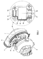
- Figure 1 shows an example of the termination 1 of a pipe delivering oil to a turbine 2 of an engine not illustrated in the drawing.
- the termination 1 is fixed to a flange 3 by means of a nut 4.
- the protective device of the termination 1 comprises two half-bearings 5 and 6 which are coupled and fastened together by means of screws 7.
- the two half-bearings are substantially the same, one of which (6) is illustrated in the enlarged view at the side. It comprises:
- a seal 12 may be applied to the lateral surfaces of the half bearings.
- it may be a previously applied silicone seal with slight grooving.
- the seal 12 may comprise protrusions 15 on the rim for a better sealing.
- Anti-vibration keys 14 may be present, for example on the collar 10, suitable to prevent the clearance between the metal parts from turning into a possible knocking effect between the surfaces and thus generating noise.
- Holes 13 are provided for the fastening screws that fasten the two half-bearings together.
- the two half-bearings can be made of any material, provided said material guarantees resistance to temperatures of up to 190°C, for example resin or plastic, or die-cast or precision-cast aluminium.
- the protective device is mounted after tightening the pipe termination to the engine, thus it can also be advantageously used on existing engines that have been in use for some time.
- an alternative embodiment of the protective device is suitable for use on pipe terminations mounted on polygonal head screw connections (e.g. with a hex head) instead of flange connections.
- the collar 10 of the half-bearing at the side opposite the pipe termination has no grooves 11 connecting the inside with the outside, in that the function of discharging the fluid, which may leak into the protective device in the event of a fracture in the pipe termination, is performed by the non-coinciding shapes of the collar 10 and of the polygonal head of the nut connection, the edges of which coincide with the inside surface of the collar 10, while the central parts are further away, acting as grooves.
Landscapes
- Engineering & Computer Science (AREA)
- General Engineering & Computer Science (AREA)
- Mechanical Engineering (AREA)
- Chemical & Material Sciences (AREA)
- Combustion & Propulsion (AREA)
- Rigid Pipes And Flexible Pipes (AREA)
- Gasket Seals (AREA)
- Pharmaceuticals Containing Other Organic And Inorganic Compounds (AREA)
- Sliding-Contact Bearings (AREA)
- Pipe Accessories (AREA)
Abstract
Description
- The present invention relates to a protective device for terminations of pipes carrying fluids under pressure in an engine, especially for marine or special applications.
- The field of application of the present invention especially regards engines for marine or special applications, in which the main parts of the surface of the engine close to the pipes delivering pressurized fluids do not reach excessively high temperatures, in that these parts are generally clad in adiabatic jackets, or with liquid-cooled air gaps, for thermal decoupling from the surrounding environment.
- Also in order to meet safety standards, pipes outside the engine that deliver pressurized fluids, especially fuel and oil, at not particularly high pressures (for instance around 5 bar), must be appropriately shielded against the possibility of unexpected fracturing, for instance due to thermal shock, vibrations or defects in materials.
- In particular, in the event of a fracture, it is necessary to prevent the pipe terminations from generating sudden splashes of fluid that can be scattered over the engine and ignite when coming into contact with the hottest parts thereof, such as turbines, exhaust manifolds, cylinder heads (in the area of the gas exhaust openings).
- Moreover it must be possible to recognize the point of failure in order to carry out the necessary repair operations.
- Protective jacketing systems using soft, not stiff, fire-retardant materials that are wrapped around the pipes are known in the prior art: however, these materials can become impregnated with fluid and thus eventually lose their protective properties. Moreover they are not the ideal solution for protecting pipe terminations.
- Therefore the purpose of this invention is to produce a protective device for terminations of pipes carrying fluids under pressure, especially oil and fuel, in an engine, especially for marine applications, which is capable of overcoming the aforesaid drawbacks.
- The object of the present invention is a protective device for the pipe termination comprising two coupled half-bearings, that envelop the termination at the point of connection to the engine structure. There is a double seal that completely encapsulates the pipe termination.
- Moreover discharge ducts are provided to allow the fluid leaking from the fractured pipe to flow outwards in a visible manner, consisting of drainage ducts through which the fluid can be seen to flow, in order to locate and repair the point of failure.
- In this way the engine is still soiled, but at controlled and desired points, in which the temperatures are not high, and not at random with splashing of parts that can reach high temperatures.
- In particular the present invention relates to a protective device for terminations of pipes carrying fluids under pressure, especially oil and fuel, in an engine, especially for marine applications, as described more fully in the claims, which are an integral part of this description.
- Further characteristics and advantages of the invention will be more apparent in the light of the detailed description of a preferred embodiment and of an alternative embodiment thereof, illustrated, by way of a non-limiting example, with the aid of the accompanying drawings, wherein:
- figure 1 shows an example of the protective device according to the present invention;
- figure 2 shows a variant thereof.
- Figure 1 shows an example of the
termination 1 of a pipe delivering oil to aturbine 2 of an engine not illustrated in the drawing. - The
termination 1 is fixed to aflange 3 by means of anut 4. - The protective device of the
termination 1 comprises two half-bearings screws 7. - The two half-bearings are substantially the same, one of which (6) is illustrated in the enlarged view at the side. It comprises:
- a
central part 8 suitable to contain thenut 4, or in any case to completely envelop the fixing element of thepipe termination 1; - a
collar 9 at the pipe termination side, having a diameter of a size such as to seal thepipe termination 1; - a
collar 10 at the side opposite the pipe termination, comprising a system to discharge the fluid that may leak into the protective device in case of fracturing of the pipe termination: in particular it comprisesgrooves 11 connecting the inside with the outside. - Moreover a
seal 12 may be applied to the lateral surfaces of the half bearings. For instance it may be a previously applied silicone seal with slight grooving. Theseal 12 may compriseprotrusions 15 on the rim for a better sealing. - "Anti-vibration keys" 14 may be present, for example on the
collar 10, suitable to prevent the clearance between the metal parts from turning into a possible knocking effect between the surfaces and thus generating noise. -
Holes 13 are provided for the fastening screws that fasten the two half-bearings together. - The two half-bearings can be made of any material, provided said material guarantees resistance to temperatures of up to 190°C, for example resin or plastic, or die-cast or precision-cast aluminium.
- The protective device is mounted after tightening the pipe termination to the engine, thus it can also be advantageously used on existing engines that have been in use for some time.
- With reference to Fig. 2, an alternative embodiment of the protective device is suitable for use on pipe terminations mounted on polygonal head screw connections (e.g. with a hex head) instead of flange connections.
- In this case the
collar 10 of the half-bearing at the side opposite the pipe termination has nogrooves 11 connecting the inside with the outside, in that the function of discharging the fluid, which may leak into the protective device in the event of a fracture in the pipe termination, is performed by the non-coinciding shapes of thecollar 10 and of the polygonal head of the nut connection, the edges of which coincide with the inside surface of thecollar 10, while the central parts are further away, acting as grooves. - It will be apparent to the person skilled in the art that other alternative and equivalent embodiments of the invention can be conceived and reduced to practice without departing from the true spirit of the invention.
- From the description set forth above it will be possible for the person skilled in the art to embody the invention without introducing any further construction details.
Claims (9)
- Protective device for terminations of pipes carrying fluids under pressure in an engine, especially for marine or special applications,
characterized in that it comprises:- two coupled half-bearings (5, 6), that envelop the termination at the point of connection to said engine, completely encapsulating the pipe termination,- discharge ducts (11) suitable to allow said fluid to flow outwards in a visible manner, in case of fracturing of said terminations. - Device according to claim 1, characterized in that each of said half-bearings comprises:- a central part (8) suitable to completely encapsulate a fastening element (4) of said termination (1);- a first collar (9) at the pipe termination side, of a size such as to seal said termination (1);- a second collar (10) at the side opposite the pipe termination.
- Device according to claim 2, characterized in that said second collar (10) comprises grooves (11) connecting the inside with the outside of the device, suitable for forming said discharge ducts.
- Device according to claim 2, characterized in that, in case of pipe terminations mounted on polygonal head screw connections, said second collar (10) has a shape that does not coincide with that of said polygonal head, so that said discharge ducts are formed by said non-coinciding shapes.
- Device according to claim 2, characterized in that it comprises a seal (12) at the lateral surfaces.
- Device according to claim 4, characterized in that said seal (12) is a previously applied silicone seal with grooves in said lateral surfaces.
- Device according to claim 2, characterized in that it comprises holes (13) for the fastening screws that fasten the two half-bearings together.
- Device according to claim 5, characterized in that said seal (12) comprises protrusions (15) on the rim.
- Device according to claim 2, characterized in that "anti-vibration keys" (14) are present on the second collar (10), to prevent the clearance between the metal parts from turning into a possible knocking effect between the surfaces and thus generating noise.
Applications Claiming Priority (1)
| Application Number | Priority Date | Filing Date | Title |
|---|---|---|---|
| IT000940A ITMI20060940A1 (en) | 2006-05-12 | 2006-05-12 | PROTECTIVE DEVICE FOR THE TERMINATION OF PIPES OF FUIDES IN PRESSURE OF A MOTOR GROUP, ESPECIALLY FOR MARINE OR SPECIAL APPLICATIONS |
Publications (4)
| Publication Number | Publication Date |
|---|---|
| EP1854994A2 true EP1854994A2 (en) | 2007-11-14 |
| EP1854994A3 EP1854994A3 (en) | 2010-07-21 |
| EP1854994B1 EP1854994B1 (en) | 2012-01-18 |
| EP1854994B8 EP1854994B8 (en) | 2012-03-21 |
Family
ID=36698919
Family Applications (1)
| Application Number | Title | Priority Date | Filing Date |
|---|---|---|---|
| EP07107927A Active EP1854994B8 (en) | 2006-05-12 | 2007-05-10 | Protective device for terminations of pipes carrying fluids under pressure in an engine, especially for marine or special applications |
Country Status (4)
| Country | Link |
|---|---|
| EP (1) | EP1854994B8 (en) |
| AT (1) | ATE542044T1 (en) |
| ES (1) | ES2380700T3 (en) |
| IT (1) | ITMI20060940A1 (en) |
Family Cites Families (8)
| Publication number | Priority date | Publication date | Assignee | Title |
|---|---|---|---|---|
| GB1392121A (en) * | 1972-05-06 | 1975-04-30 | Semt | Fuel injection systems |
| US4114929A (en) * | 1975-08-13 | 1978-09-19 | Robert Bosch Gmbh | Plastic pipe or hose connection for fuel conduits |
| DE3244179A1 (en) * | 1982-11-30 | 1984-05-30 | Alfred Teves Gmbh, 6000 Frankfurt | BRAKE HOSE PIPE |
| JPS59153966A (en) * | 1983-02-22 | 1984-09-01 | Yanmar Diesel Engine Co Ltd | Fuel injection pipe covering structure of diesel engine |
| DE3638579C2 (en) * | 1986-11-12 | 1994-09-01 | Gruenzweig & Hartmann Montage | High-temperature thermal insulation system for high-performance shaft engines |
| US5895076A (en) * | 1996-11-04 | 1999-04-20 | Tyler J. Elliot | Hose coupling shroud |
| JP4036412B2 (en) * | 1999-05-14 | 2008-01-23 | 臼井国際産業株式会社 | High pressure fuel injection pipe for diesel engine |
| JP2004036751A (en) * | 2002-07-03 | 2004-02-05 | Fujikin Inc | Untwisting device for pipe joint |
-
2006
- 2006-05-12 IT IT000940A patent/ITMI20060940A1/en unknown
-
2007
- 2007-05-10 AT AT07107927T patent/ATE542044T1/en active
- 2007-05-10 EP EP07107927A patent/EP1854994B8/en active Active
- 2007-05-10 ES ES07107927T patent/ES2380700T3/en active Active
Also Published As
| Publication number | Publication date |
|---|---|
| EP1854994B1 (en) | 2012-01-18 |
| EP1854994A3 (en) | 2010-07-21 |
| ES2380700T3 (en) | 2012-05-17 |
| ATE542044T1 (en) | 2012-02-15 |
| ITMI20060940A1 (en) | 2007-11-13 |
| EP1854994B8 (en) | 2012-03-21 |
Similar Documents
| Publication | Publication Date | Title |
|---|---|---|
| JPH1113593A (en) | Combustion gas seal for injector | |
| CN105422998B (en) | Bulkhead fitment combination part | |
| US20090079185A1 (en) | Pipe assembly | |
| CN102953863B (en) | Coolant seals part and manifold gasket component | |
| EP3957842A1 (en) | Aircraft firewall feedthrough device | |
| US8701625B2 (en) | Diesel engine, predetermined breaking component for diesel engine as well as method for avoiding damages to a diesel engine | |
| US20080066805A1 (en) | Pressure tank system with heat conducting layer | |
| CN107567540A (en) | The component being made up of cylinder head and fuel injector | |
| WO2018198951A1 (en) | Spark plug sleeve | |
| ITMI20112391A1 (en) | DEVICES AND METHODS TO IMPLEMENT VALVES | |
| US20110132329A1 (en) | Fuel injection valve for arrangement in a combustion chamber of an internal combustion engine | |
| EP1854994B1 (en) | Protective device for terminations of pipes carrying fluids under pressure in an engine, especially for marine or special applications | |
| US10428780B2 (en) | Fuel injector mounting system for mounting an injector to an engine cylinder liner | |
| CN104603422A (en) | Cylinder head with sensor sleeve | |
| EP3171015B1 (en) | Terminal sealing structure for fuel rail for gasoline direct-injection engine | |
| US20140314551A1 (en) | Bearing housing of an exhaust-gas turbocharger | |
| CN108138653A (en) | For the oil draining system of the bear box of gas-turbine unit | |
| CN101432561B (en) | Fluid conduit with self-healing protective sleeve | |
| CN108474334A (en) | Pipe assembly and method for connecting pipe assembly | |
| US20160087372A1 (en) | Strain relief structure | |
| CN119353103B (en) | Fireproof accessory transmission case and aircraft engine | |
| US11008891B2 (en) | Assembled turbine housing | |
| CN112302737A (en) | Sealing device, engine and ground combustion engine | |
| US20170350347A1 (en) | Oil flow control for an engine by deflection | |
| JPH06346993A (en) | Piping structure for high temperature part |
Legal Events
| Date | Code | Title | Description |
|---|---|---|---|
| PUAI | Public reference made under article 153(3) epc to a published international application that has entered the european phase |
Free format text: ORIGINAL CODE: 0009012 |
|
| AK | Designated contracting states |
Kind code of ref document: A2 Designated state(s): AT BE BG CH CY CZ DE DK EE ES FI FR GB GR HU IE IS IT LI LT LU LV MC MT NL PL PT RO SE SI SK TR |
|
| AX | Request for extension of the european patent |
Extension state: AL BA HR MK YU |
|
| PUAL | Search report despatched |
Free format text: ORIGINAL CODE: 0009013 |
|
| AK | Designated contracting states |
Kind code of ref document: A3 Designated state(s): AT BE BG CH CY CZ DE DK EE ES FI FR GB GR HU IE IS IT LI LT LU LV MC MT NL PL PT RO SE SI SK TR |
|
| AX | Request for extension of the european patent |
Extension state: AL BA HR MK RS |
|
| 17P | Request for examination filed |
Effective date: 20100709 |
|
| RIC1 | Information provided on ipc code assigned before grant |
Ipc: F02M 55/02 20060101AFI20101223BHEP Ipc: F16L 35/00 20060101ALI20101223BHEP |
|
| AKX | Designation fees paid |
Designated state(s): AT BE BG CH CY CZ DE DK EE ES FI FR GB GR HU IE IS IT LI LT LU LV MC MT NL PL PT RO SE SI SK TR |
|
| GRAP | Despatch of communication of intention to grant a patent |
Free format text: ORIGINAL CODE: EPIDOSNIGR1 |
|
| GRAS | Grant fee paid |
Free format text: ORIGINAL CODE: EPIDOSNIGR3 |
|
| GRAA | (expected) grant |
Free format text: ORIGINAL CODE: 0009210 |
|
| RAP1 | Party data changed (applicant data changed or rights of an application transferred) |
Owner name: FPT INDUSTRIE S.P.A. |
|
| AK | Designated contracting states |
Kind code of ref document: B1 Designated state(s): AT BE BG CH CY CZ DE DK EE ES FI FR GB GR HU IE IS IT LI LT LU LV MC MT NL PL PT RO SE SI SK TR |
|
| REG | Reference to a national code |
Ref country code: GB Ref legal event code: FG4D |
|
| RAP2 | Party data changed (patent owner data changed or rights of a patent transferred) |
Owner name: FPT INDUSTRIAL S.P.A. |
|
| REG | Reference to a national code |
Ref country code: CH Ref legal event code: EP |
|
| REG | Reference to a national code |
Ref country code: IE Ref legal event code: FG4D Ref country code: AT Ref legal event code: REF Ref document number: 542044 Country of ref document: AT Kind code of ref document: T Effective date: 20120215 |
|
| REG | Reference to a national code |
Ref country code: DE Ref legal event code: R096 Ref document number: 602007020117 Country of ref document: DE Effective date: 20120315 |
|
| REG | Reference to a national code |
Ref country code: SE Ref legal event code: TRGR |
|
| REG | Reference to a national code |
Ref country code: NL Ref legal event code: T3 |
|
| REG | Reference to a national code |
Ref country code: ES Ref legal event code: FG2A Ref document number: 2380700 Country of ref document: ES Kind code of ref document: T3 Effective date: 20120517 |
|
| LTIE | Lt: invalidation of european patent or patent extension |
Effective date: 20120118 |
|
| PG25 | Lapsed in a contracting state [announced via postgrant information from national office to epo] |
Ref country code: BE Free format text: LAPSE BECAUSE OF FAILURE TO SUBMIT A TRANSLATION OF THE DESCRIPTION OR TO PAY THE FEE WITHIN THE PRESCRIBED TIME-LIMIT Effective date: 20120118 Ref country code: LT Free format text: LAPSE BECAUSE OF FAILURE TO SUBMIT A TRANSLATION OF THE DESCRIPTION OR TO PAY THE FEE WITHIN THE PRESCRIBED TIME-LIMIT Effective date: 20120118 Ref country code: BG Free format text: LAPSE BECAUSE OF FAILURE TO SUBMIT A TRANSLATION OF THE DESCRIPTION OR TO PAY THE FEE WITHIN THE PRESCRIBED TIME-LIMIT Effective date: 20120418 Ref country code: IS Free format text: LAPSE BECAUSE OF FAILURE TO SUBMIT A TRANSLATION OF THE DESCRIPTION OR TO PAY THE FEE WITHIN THE PRESCRIBED TIME-LIMIT Effective date: 20120518 |
|
| PG25 | Lapsed in a contracting state [announced via postgrant information from national office to epo] |
Ref country code: GR Free format text: LAPSE BECAUSE OF FAILURE TO SUBMIT A TRANSLATION OF THE DESCRIPTION OR TO PAY THE FEE WITHIN THE PRESCRIBED TIME-LIMIT Effective date: 20120419 Ref country code: PT Free format text: LAPSE BECAUSE OF FAILURE TO SUBMIT A TRANSLATION OF THE DESCRIPTION OR TO PAY THE FEE WITHIN THE PRESCRIBED TIME-LIMIT Effective date: 20120518 Ref country code: LV Free format text: LAPSE BECAUSE OF FAILURE TO SUBMIT A TRANSLATION OF THE DESCRIPTION OR TO PAY THE FEE WITHIN THE PRESCRIBED TIME-LIMIT Effective date: 20120118 Ref country code: FI Free format text: LAPSE BECAUSE OF FAILURE TO SUBMIT A TRANSLATION OF THE DESCRIPTION OR TO PAY THE FEE WITHIN THE PRESCRIBED TIME-LIMIT Effective date: 20120118 Ref country code: PL Free format text: LAPSE BECAUSE OF FAILURE TO SUBMIT A TRANSLATION OF THE DESCRIPTION OR TO PAY THE FEE WITHIN THE PRESCRIBED TIME-LIMIT Effective date: 20120118 |
|
| PG25 | Lapsed in a contracting state [announced via postgrant information from national office to epo] |
Ref country code: CY Free format text: LAPSE BECAUSE OF FAILURE TO SUBMIT A TRANSLATION OF THE DESCRIPTION OR TO PAY THE FEE WITHIN THE PRESCRIBED TIME-LIMIT Effective date: 20120118 |
|
| PG25 | Lapsed in a contracting state [announced via postgrant information from national office to epo] |
Ref country code: EE Free format text: LAPSE BECAUSE OF FAILURE TO SUBMIT A TRANSLATION OF THE DESCRIPTION OR TO PAY THE FEE WITHIN THE PRESCRIBED TIME-LIMIT Effective date: 20120118 Ref country code: DK Free format text: LAPSE BECAUSE OF FAILURE TO SUBMIT A TRANSLATION OF THE DESCRIPTION OR TO PAY THE FEE WITHIN THE PRESCRIBED TIME-LIMIT Effective date: 20120118 Ref country code: CZ Free format text: LAPSE BECAUSE OF FAILURE TO SUBMIT A TRANSLATION OF THE DESCRIPTION OR TO PAY THE FEE WITHIN THE PRESCRIBED TIME-LIMIT Effective date: 20120118 Ref country code: SI Free format text: LAPSE BECAUSE OF FAILURE TO SUBMIT A TRANSLATION OF THE DESCRIPTION OR TO PAY THE FEE WITHIN THE PRESCRIBED TIME-LIMIT Effective date: 20120118 Ref country code: RO Free format text: LAPSE BECAUSE OF FAILURE TO SUBMIT A TRANSLATION OF THE DESCRIPTION OR TO PAY THE FEE WITHIN THE PRESCRIBED TIME-LIMIT Effective date: 20120118 |
|
| REG | Reference to a national code |
Ref country code: AT Ref legal event code: MK05 Ref document number: 542044 Country of ref document: AT Kind code of ref document: T Effective date: 20120118 |
|
| PLBE | No opposition filed within time limit |
Free format text: ORIGINAL CODE: 0009261 |
|
| STAA | Information on the status of an ep patent application or granted ep patent |
Free format text: STATUS: NO OPPOSITION FILED WITHIN TIME LIMIT |
|
| PG25 | Lapsed in a contracting state [announced via postgrant information from national office to epo] |
Ref country code: SK Free format text: LAPSE BECAUSE OF FAILURE TO SUBMIT A TRANSLATION OF THE DESCRIPTION OR TO PAY THE FEE WITHIN THE PRESCRIBED TIME-LIMIT Effective date: 20120118 |
|
| 26N | No opposition filed |
Effective date: 20121019 |
|
| PG25 | Lapsed in a contracting state [announced via postgrant information from national office to epo] |
Ref country code: MC Free format text: LAPSE BECAUSE OF NON-PAYMENT OF DUE FEES Effective date: 20120531 |
|
| REG | Reference to a national code |
Ref country code: CH Ref legal event code: PL |
|
| PG25 | Lapsed in a contracting state [announced via postgrant information from national office to epo] |
Ref country code: AT Free format text: LAPSE BECAUSE OF FAILURE TO SUBMIT A TRANSLATION OF THE DESCRIPTION OR TO PAY THE FEE WITHIN THE PRESCRIBED TIME-LIMIT Effective date: 20120118 Ref country code: CH Free format text: LAPSE BECAUSE OF NON-PAYMENT OF DUE FEES Effective date: 20120531 Ref country code: LI Free format text: LAPSE BECAUSE OF NON-PAYMENT OF DUE FEES Effective date: 20120531 |
|
| REG | Reference to a national code |
Ref country code: DE Ref legal event code: R097 Ref document number: 602007020117 Country of ref document: DE Effective date: 20121019 |
|
| REG | Reference to a national code |
Ref country code: IE Ref legal event code: MM4A |
|
| PG25 | Lapsed in a contracting state [announced via postgrant information from national office to epo] |
Ref country code: IE Free format text: LAPSE BECAUSE OF NON-PAYMENT OF DUE FEES Effective date: 20120510 |
|
| PG25 | Lapsed in a contracting state [announced via postgrant information from national office to epo] |
Ref country code: MT Free format text: LAPSE BECAUSE OF FAILURE TO SUBMIT A TRANSLATION OF THE DESCRIPTION OR TO PAY THE FEE WITHIN THE PRESCRIBED TIME-LIMIT Effective date: 20120118 |
|
| PG25 | Lapsed in a contracting state [announced via postgrant information from national office to epo] |
Ref country code: TR Free format text: LAPSE BECAUSE OF FAILURE TO SUBMIT A TRANSLATION OF THE DESCRIPTION OR TO PAY THE FEE WITHIN THE PRESCRIBED TIME-LIMIT Effective date: 20120118 |
|
| PG25 | Lapsed in a contracting state [announced via postgrant information from national office to epo] |
Ref country code: LU Free format text: LAPSE BECAUSE OF NON-PAYMENT OF DUE FEES Effective date: 20120510 |
|
| PG25 | Lapsed in a contracting state [announced via postgrant information from national office to epo] |
Ref country code: HU Free format text: LAPSE BECAUSE OF FAILURE TO SUBMIT A TRANSLATION OF THE DESCRIPTION OR TO PAY THE FEE WITHIN THE PRESCRIBED TIME-LIMIT Effective date: 20070510 |
|
| REG | Reference to a national code |
Ref country code: FR Ref legal event code: PLFP Year of fee payment: 9 |
|
| REG | Reference to a national code |
Ref country code: FR Ref legal event code: PLFP Year of fee payment: 10 |
|
| REG | Reference to a national code |
Ref country code: FR Ref legal event code: PLFP Year of fee payment: 11 |
|
| REG | Reference to a national code |
Ref country code: FR Ref legal event code: PLFP Year of fee payment: 12 |
|
| P01 | Opt-out of the competence of the unified patent court (upc) registered |
Effective date: 20230519 |
|
| PGFP | Annual fee paid to national office [announced via postgrant information from national office to epo] |
Ref country code: SE Payment date: 20250228 Year of fee payment: 19 |
|
| PGFP | Annual fee paid to national office [announced via postgrant information from national office to epo] |
Ref country code: NL Payment date: 20250526 Year of fee payment: 19 |
|
| PGFP | Annual fee paid to national office [announced via postgrant information from national office to epo] |
Ref country code: DE Payment date: 20250528 Year of fee payment: 19 |
|
| PGFP | Annual fee paid to national office [announced via postgrant information from national office to epo] |
Ref country code: GB Payment date: 20250520 Year of fee payment: 19 Ref country code: ES Payment date: 20250612 Year of fee payment: 19 |
|
| PGFP | Annual fee paid to national office [announced via postgrant information from national office to epo] |
Ref country code: IT Payment date: 20250512 Year of fee payment: 19 |
|
| PGFP | Annual fee paid to national office [announced via postgrant information from national office to epo] |
Ref country code: FR Payment date: 20250526 Year of fee payment: 19 |