EP1854983A2 - Engine controller - Google Patents
Engine controller Download PDFInfo
- Publication number
- EP1854983A2 EP1854983A2 EP07008952A EP07008952A EP1854983A2 EP 1854983 A2 EP1854983 A2 EP 1854983A2 EP 07008952 A EP07008952 A EP 07008952A EP 07008952 A EP07008952 A EP 07008952A EP 1854983 A2 EP1854983 A2 EP 1854983A2
- Authority
- EP
- European Patent Office
- Prior art keywords
- fuel ratio
- air
- combustion
- engine
- fuel
- Prior art date
- Legal status (The legal status is an assumption and is not a legal conclusion. Google has not performed a legal analysis and makes no representation as to the accuracy of the status listed.)
- Withdrawn
Links
- 239000000446 fuel Substances 0.000 claims abstract description 514
- 238000002485 combustion reaction Methods 0.000 claims abstract description 368
- 238000001514 detection method Methods 0.000 claims abstract description 64
- 238000012937 correction Methods 0.000 claims description 27
- 239000000498 cooling water Substances 0.000 claims description 10
- 238000002347 injection Methods 0.000 description 38
- 239000007924 injection Substances 0.000 description 38
- 238000000034 method Methods 0.000 description 17
- 230000006870 function Effects 0.000 description 14
- QVGXLLKOCUKJST-UHFFFAOYSA-N atomic oxygen Chemical compound [O] QVGXLLKOCUKJST-UHFFFAOYSA-N 0.000 description 11
- 239000003054 catalyst Substances 0.000 description 11
- 239000001301 oxygen Substances 0.000 description 11
- 229910052760 oxygen Inorganic materials 0.000 description 11
- 238000009834 vaporization Methods 0.000 description 11
- 230000008016 vaporization Effects 0.000 description 11
- 230000000694 effects Effects 0.000 description 10
- 230000005540 biological transmission Effects 0.000 description 7
- 238000012545 processing Methods 0.000 description 6
- 239000007789 gas Substances 0.000 description 5
- 238000011144 upstream manufacturing Methods 0.000 description 5
- XLYOFNOQVPJJNP-UHFFFAOYSA-N water Substances O XLYOFNOQVPJJNP-UHFFFAOYSA-N 0.000 description 4
- 230000008569 process Effects 0.000 description 3
- 230000001276 controlling effect Effects 0.000 description 2
- 230000002596 correlated effect Effects 0.000 description 2
- 238000004880 explosion Methods 0.000 description 2
- 238000005259 measurement Methods 0.000 description 2
- 238000010248 power generation Methods 0.000 description 2
- 230000004044 response Effects 0.000 description 2
- 238000013459 approach Methods 0.000 description 1
- 230000007423 decrease Effects 0.000 description 1
- 238000005516 engineering process Methods 0.000 description 1
- 230000006872 improvement Effects 0.000 description 1
- 230000002401 inhibitory effect Effects 0.000 description 1
- 230000000977 initiatory effect Effects 0.000 description 1
- 239000000203 mixture Substances 0.000 description 1
- 230000004043 responsiveness Effects 0.000 description 1
- 239000000523 sample Substances 0.000 description 1
- 238000005070 sampling Methods 0.000 description 1
- 230000001360 synchronised effect Effects 0.000 description 1
- 238000012360 testing method Methods 0.000 description 1
- 230000007704 transition Effects 0.000 description 1
- 239000002912 waste gas Substances 0.000 description 1
Images


Classifications
-
- F—MECHANICAL ENGINEERING; LIGHTING; HEATING; WEAPONS; BLASTING
- F02—COMBUSTION ENGINES; HOT-GAS OR COMBUSTION-PRODUCT ENGINE PLANTS
- F02D—CONTROLLING COMBUSTION ENGINES
- F02D41/00—Electrical control of supply of combustible mixture or its constituents
- F02D41/02—Circuit arrangements for generating control signals
- F02D41/04—Introducing corrections for particular operating conditions
- F02D41/06—Introducing corrections for particular operating conditions for engine starting or warming up
- F02D41/062—Introducing corrections for particular operating conditions for engine starting or warming up for starting
-
- F—MECHANICAL ENGINEERING; LIGHTING; HEATING; WEAPONS; BLASTING
- F02—COMBUSTION ENGINES; HOT-GAS OR COMBUSTION-PRODUCT ENGINE PLANTS
- F02D—CONTROLLING COMBUSTION ENGINES
- F02D35/00—Controlling engines, dependent on conditions exterior or interior to engines, not otherwise provided for
- F02D35/02—Controlling engines, dependent on conditions exterior or interior to engines, not otherwise provided for on interior conditions
- F02D35/023—Controlling engines, dependent on conditions exterior or interior to engines, not otherwise provided for on interior conditions by determining the cylinder pressure
-
- F—MECHANICAL ENGINEERING; LIGHTING; HEATING; WEAPONS; BLASTING
- F02—COMBUSTION ENGINES; HOT-GAS OR COMBUSTION-PRODUCT ENGINE PLANTS
- F02D—CONTROLLING COMBUSTION ENGINES
- F02D35/00—Controlling engines, dependent on conditions exterior or interior to engines, not otherwise provided for
- F02D35/02—Controlling engines, dependent on conditions exterior or interior to engines, not otherwise provided for on interior conditions
- F02D35/025—Controlling engines, dependent on conditions exterior or interior to engines, not otherwise provided for on interior conditions by determining temperatures inside the cylinder, e.g. combustion temperatures
-
- F—MECHANICAL ENGINEERING; LIGHTING; HEATING; WEAPONS; BLASTING
- F02—COMBUSTION ENGINES; HOT-GAS OR COMBUSTION-PRODUCT ENGINE PLANTS
- F02D—CONTROLLING COMBUSTION ENGINES
- F02D41/00—Electrical control of supply of combustible mixture or its constituents
- F02D41/02—Circuit arrangements for generating control signals
- F02D41/14—Introducing closed-loop corrections
- F02D41/1438—Introducing closed-loop corrections using means for determining characteristics of the combustion gases; Sensors therefor
- F02D41/1444—Introducing closed-loop corrections using means for determining characteristics of the combustion gases; Sensors therefor characterised by the characteristics of the combustion gases
- F02D41/1454—Introducing closed-loop corrections using means for determining characteristics of the combustion gases; Sensors therefor characterised by the characteristics of the combustion gases the characteristics being an oxygen content or concentration or the air-fuel ratio
- F02D41/1458—Introducing closed-loop corrections using means for determining characteristics of the combustion gases; Sensors therefor characterised by the characteristics of the combustion gases the characteristics being an oxygen content or concentration or the air-fuel ratio with determination means using an estimation
-
- F—MECHANICAL ENGINEERING; LIGHTING; HEATING; WEAPONS; BLASTING
- F02—COMBUSTION ENGINES; HOT-GAS OR COMBUSTION-PRODUCT ENGINE PLANTS
- F02D—CONTROLLING COMBUSTION ENGINES
- F02D2200/00—Input parameters for engine control
- F02D2200/02—Input parameters for engine control the parameters being related to the engine
- F02D2200/10—Parameters related to the engine output, e.g. engine torque or engine speed
- F02D2200/1012—Engine speed gradient
-
- F—MECHANICAL ENGINEERING; LIGHTING; HEATING; WEAPONS; BLASTING
- F02—COMBUSTION ENGINES; HOT-GAS OR COMBUSTION-PRODUCT ENGINE PLANTS
- F02D—CONTROLLING COMBUSTION ENGINES
- F02D2250/00—Engine control related to specific problems or objectives
- F02D2250/18—Control of the engine output torque
-
- F—MECHANICAL ENGINEERING; LIGHTING; HEATING; WEAPONS; BLASTING
- F02—COMBUSTION ENGINES; HOT-GAS OR COMBUSTION-PRODUCT ENGINE PLANTS
- F02D—CONTROLLING COMBUSTION ENGINES
- F02D37/00—Non-electrical conjoint control of two or more functions of engines, not otherwise provided for
- F02D37/02—Non-electrical conjoint control of two or more functions of engines, not otherwise provided for one of the functions being ignition
-
- F—MECHANICAL ENGINEERING; LIGHTING; HEATING; WEAPONS; BLASTING
- F02—COMBUSTION ENGINES; HOT-GAS OR COMBUSTION-PRODUCT ENGINE PLANTS
- F02D—CONTROLLING COMBUSTION ENGINES
- F02D41/00—Electrical control of supply of combustible mixture or its constituents
- F02D41/02—Circuit arrangements for generating control signals
- F02D41/14—Introducing closed-loop corrections
- F02D41/1497—With detection of the mechanical response of the engine
- F02D41/1498—With detection of the mechanical response of the engine measuring engine roughness
-
- F—MECHANICAL ENGINEERING; LIGHTING; HEATING; WEAPONS; BLASTING
- F02—COMBUSTION ENGINES; HOT-GAS OR COMBUSTION-PRODUCT ENGINE PLANTS
- F02D—CONTROLLING COMBUSTION ENGINES
- F02D41/00—Electrical control of supply of combustible mixture or its constituents
- F02D41/24—Electrical control of supply of combustible mixture or its constituents characterised by the use of digital means
- F02D41/2406—Electrical control of supply of combustible mixture or its constituents characterised by the use of digital means using essentially read only memories
- F02D41/2425—Particular ways of programming the data
- F02D41/2429—Methods of calibrating or learning
- F02D41/2451—Methods of calibrating or learning characterised by what is learned or calibrated
- F02D41/2454—Learning of the air-fuel ratio control
Definitions
- the present invention relates to an engine controller that controls the amount of fuel to be injected (air-fuel ratio) and other factors and, more particularly, to a controller for a robust engine that can efficiently prevents air-flow ratio precision from being worsened at the time of start.
- exhaust emission from engines is dominant when they are started.
- Highly precious air-fuel ratio control is also effective in improving the engine exhaust emission characteristics at the time of start.
- exhaust air-fuel ratio feedback control in which an exhaust air-fuel ratio is detected and the amount of fuel to be injected is then corrected, is usually started at a fixed time (10 to 20 seconds) after the start.
- An air-fuel ratio sensor is activated at an early stage and a preheat system is introduced, so there is the prospect that exhaust air-fuel ratio feedback control initiated at the start will be put into practical use.
- fuel vaporization rate is low because, for example, temperature is low or heavy fuel is used, fuel that entered the combustion chamber is exhausted into the exhaust path without being burned. The exhausted fuel is oxidized in the exhaust path and by an exhaust air-fuel ratio sensor probe. When this happens, the exhaust air-fuel ratio is higher than the actual combustion air-fuel ratio.
- the combustion air-fuel ratio is not properly controlled (the combustion does not approach stoichiometric combustion) and an excessively lean burn thereby occurs, lowering exhaust purifying performance and running operation.
- a technology for initiating the detection of the combustion air-fuel ratio with high precision at the time of start and controlling the combustion air-fuel ratio is necessary.
- Patent Document 1 Japanese Patent Laid-open No. 2003-83133
- Patent Document 2 Japanese Patent Laid-open No. 10-30537
- Patent Document 1 discloses a control method in which when the temperature at the start is low, a lower fuel correction limit is restricted according to exhaust air-fuel ratio feedback from an exhaust air-fuel ratio sensor so as to prevent an excessively lean burn from occurring.
- a lower fuel correction limit is restricted according to exhaust air-fuel ratio feedback from an exhaust air-fuel ratio sensor so as to prevent an excessively lean burn from occurring.
- the air-fuel ratio is just prevented from being excessively leaned; the combustion air-fuel ratio cannot be controlled to an appropriate air-fuel ratio.
- the lower limit is determined according to a particular fuel state. Accordingly, when the lower limit is determined for a soft fuel, for example, the possibility of a lean firemiss is increased; when the lower limit is determined for a heavy fuel, the control range for leaning a soft fuel is more restrictive than necessary.
- Patent Document 2 discloses another control method in which a response characteristic until the amount of fuel to be corrected on the basis of air-fuel ratio feedback is reflected in combustion is detected for each cylinder according to a rotational variation so as to appropriately correct the ignition timing.
- the ignition timing is just controlled by estimating a responsiveness from fuel ignition up to the control of the combustion exhaust air-fuel ratio, so the control method does not correct a difference between the exhaust air-fuel ratio and the combustion air-fuel ratio, nor does it control the combustion air-fuel ratio. Accordingly, the control method does not addresses the problems described above.
- the present invention addresses the above problems with the object of providing an inexpensive engine controller that can control the combustion air-fuel ratio at the time of start with high precision.
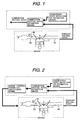
- an engine controller in a first aspect of the present invention comprises a combustion state detection or estimation means for detecting or estimating a combustion state in the combustion chamber and/or a combustion air-fuel ratio estimation means for estimating a combustion air-fuel ratio in the combustion chamber according to an exhaust air-fuel ratio and/or the detected or estimated combustion state (see FIG.1).
- the combustion state corresponds to the combustion air-fuel ratio. Accordingly, a means for detecting or estimating a combustion state is provided so as to monitor the validity of the exhaust air-fuel ratio and detect or estimate a more accurate combustion state with reference to the exhaust air-fuel ratio. It is preferable to directly detect the combustion air-fuel ratio to detect or estimate the combustion state.
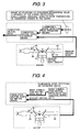
- An engine controller in a second aspect of the present invention has a means for calculating an engine control parameter according to the estimated combustion air-fuel ratio (see FIG. 2).
- the combustion state detection or estimation means estimates the combustion state according to engine revolutions or an nth-order differential value (n: integer) of the engine revolutions (see FIG. 3).
- the combustion state is detected or estimated according to variations in engine revolutions.
- the combustion state (variations in combustion) can be detected more precisely.
- the combustion state detection or estimation means estimates the combustion state according to at least one of an intra-cylinder pressure, an intra-cylinder temperature, and a generated torque in the engine (see FIG. 3).
- the combustion state is stipulated as the intra-cylinder pressure (combustion pressure), intra-cylinder temperature, and generated torque in the engine. Although none of these factors are detected in a dimension of the air-fuel ratio, they are physical quantities correlated to the combustion air-fuel ratio.
- the combustion air-fuel ratio is highly precisely detected or estimated from the detected values and the exhaust air-fuel ratio.
- an exhaust sensor for sensing the exhaust air-fuel ratio is provided in an exhaust path (see FIG. 3).
- the exhaust air-fuel ratio is stipulated as being detected by the exhaust sensor provided in the exhaust path.
- the exhaust sensor may be, for example, an O 2 sensor, an NOx sensor, or the like.
- the combustion state detection or estimation means calculates a basic combustion air-fuel ratio value from the combustion state and the combustion air-fuel ratio estimation means estimates the combustion air-fuel ratio according to the basic combustion air-fuel ratio value and the exhaust air-fuel ratio (see FIG. 4).
- the combustion state is converted to a parameter correlated to the combustion air-fuel ratio and the combustion air-fuel ratio is obtained from the basic combustion air-fuel ratio value and exhaust air-fuel ratio.
- the combustion air-fuel ratio estimation means compares the basic combustion air-fuel ratio value with the exhaust air-fuel ratio and estimates either the basic combustion air-fuel ratio value or the exhaust air-fuel ratio as the combustion air-fuel ratio according to a comparison result (see FIG. 5).
- the combustion air-fuel ratio estimation means estimates the larger of the basic combustion air-fuel ratio value and the exhaust air-fuel ratio as the combustion air-fuel ratio (see FIG. 5).
- the basic combustion air-fuel ratio value becomes leaner, that is, larger, than the exhaust air-fuel ratio.
- the basic combustion air-fuel ratio value is then used as the combustion air-fuel ratio.
- the combustion air-fuel ratio estimation means calculates the amount of exhaust air-fuel ratio correction according to the combustion state and estimates a value obtained by correcting the exhaust air-fuel ratio with the calculated amount of exhaust air-fuel ratio correction as a combustion air-fuel ratio (see FIG. 6).
- error in the exhaust air-fuel ratio is corrected according to the estimated combustion state, and the corrected exhaust air-fuel ratio is used as the combustion air-fuel ratio.
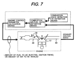
- control parameter calculation means calculates at least one of the amount of fuel to be injected, an ignition timing, and the amount of air to be inhaled as the control parameter (see FIG. 7).
- targets to be controlled are stipulated as the amount of fuel to be injected, the ignition timing, and the amount of air to be inhaled.
- An engine controller in an eleventh aspect of the present invention has a control parameter calculation permission means that permits or denies control parameter calculation, which is performed by the control parameter calculation means on the basis of the combustion air-fuel ratio, according to the running state of the engine (see FIG. 8).
- the control parameter calculation permission means permits or denies the control parameter calculation according to an engine cooling water temperature, an inhaled air temperature, a time elapsed from the time of start, the total number of cycles after the start, the total amount of air inhaled after the start, and other parameters that typify an engine temperature. That is, as described above, error in detection of the exhaust air-fuel ratio is likely to occur, particularly at a low temperature; accordingly, whether to perform the engine control parameter calculation based on the combustion air-fuel ratio is determined according to the values of the above parameters that typify an engine temperature for detecting a low-temperature condition.
- the control parameter calculation permission means permits the engine control parameter calculation on the basis of the combustion air-fuel ratio when at least one of the following conditions is met: the engine cooling water temperature is equal to or lower than a prescribed value, the temperature of air to be inhaled into the engine is equal to or lower than a prescribed value, the time elapsed after the start of the engine is equal to or less than a prescribed value, the total number of cycles after the start of the engine is equal to or smaller than a prescribed value, and the total amount of air inhaled after the start of the engine is equal to or smaller than a prescribed value.
- a low-temperature condition under which error in exhaust air-fuel ratio detection is likely to occur is detected by the above parameters that typify an engine temperature; engine control parameter calculation based on the combustion air-fuel ratio is performed only when appropriate conditions are met.
- the control parameter calculation permission means has the control parameter calculation means correct engine control parameters on the basis of the exhaust air-fuel ratio or deny the engine control parameter calculation, when a difference or a ratio between the combustion air-fuel ratio and the exhaust air-fuel ratio is equal to or greater than a prescribed value (see FIG. 9).
- a control parameter for controlling the amount of fuel is corrected according to a fed-back exhaust air-fuel ratio, or feedback control is stopped.
- the controller described in the fourteenth aspect is called exhaust air-fuel ratio feedback control by which the exhaust air-fuel ratio is fed back so as to control the amount of fuel.
- An engine controller in a sixteenth aspect of the present invention has a means for learning the relation between the combustion state and the basic combustion air-fuel ratio value according to the exhaust air-fuel ratio (see FIG. 10).
- the exhaust air-fuel ratio is used to learn the relation between the combustion state and the basic combustion air-fuel ratio value. More specifically, under a running condition in which there is no error between the combustion air-fuel ratio and the exhaust air-fuel ratio or the error is sufficiently small, the exhaust air-fuel ratio is regarded as the combustion air-fuel ratio and the relation between the combustion state and the exhaust air-fuel ratio at that time is learned as the relation between the combustion state and the combustion air-fuel ratio.
- the learning means performs the learning according to the running state of the engine (see FIG. 11).
- whether to perform the learning is determined according to the running condition of the engine.
- the learning means performs the learning when at least one of the following conditions is met: the engine cooling water temperature is equal to or higher than a prescribed value, the temperature of air to be inhaled into the engine is equal to or higher than a prescribed value, a time elapsed after the start of the engine is equal to or more than a prescribed value, the total number of cycles after the start of the engine is equal to or more than a prescribed value, and the total amount of air inhaled after the start of the engine is equal to or more than a prescribed value.
- condition in which the engine temperature is sufficiently high which is a running condition when there is no error between the combustion air-fuel ratio and the exhaust air-fuel ratio or the error is sufficiently small, is more specifically stipulated.
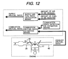
- An engine controller in a nineteenth aspect of the present invention has a means for calculating a supply air-fuel ratio according to the amount of air to be inhaled into the engine and the amount of fuel to be injected (see FIG. 12).
- the air-fuel ratio indicates a weight ratio between the amount of air and the amount of fuel
- the effect by the transmission characteristic from fuel injection to combustion is large.
- a means for calculating the supply air-fuel ratio, which is the air-fuel ratio in the intake path is provided.
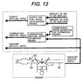
- the supply air-fuel ratio, the combustion air-fuel ratio, and the exhaust air-fuel ratio are estimated or detected independently (see FIG. 13).
- control parameter calculation means performs engine control parameter calculation according to the supply air-fuel ratio, the combustion air-fuel ratio, and the exhaust air-fuel ratio (see FIG. 14).
- the supply air-fuel ratio, combustion air-fuel ratio, and exhaust air-fuel ratio which are typical parameters for the air-fuel ratio transmission system, are used as information from which to calculate the engine control parameters, enabling the air-fuel ratio during cold engine operation, transition, and the like to be controlled with high precision.
- An engine controller in a twenty-second aspect of the present invention has a means for estimating a fuel state according to at least one of the supply air-fuel ratio, the combustion air-fuel ratio, and the exhaust air-fuel ratio (see FIG. 15).
- the characteristic of the air-fuel ratio transmission system is largely affected by the fuel vaporization rate; when, for example, the engine is cold, the fuel vaporization rate is relatively low and a difference in the fuel state is likely to cause an effect.
- the supply air-fuel ratio, combustion air-fuel ratio, and exhaust air-fuel ratio are compared to detect the fuel state.
- the combustion air-fuel ratio estimation means, the control parameter calculation means, and the fuel state estimation means handle the air-fuel ratio in a dimension of an equivalence ratio.
- the combustion air-fuel ratio is controlled to a desired air-fuel ratio.
- the combustion air-fuel ratio is indirectly controlled by detecting the exhaust air-fuel ratio, if the exhaust air-fuel ratio differs from the combustion air-fuel ratio due to the effect of unburned fuel or the like, the use of the controller in the above aspect enables the combustion air-fuel ratio, which is the original purpose, to be controlled to a desired air-fuel ratio.
- the air-fuel ratio at the start of an engine can be controlled with high precision in an inexpensive manner.
- the exhaust emission characteristic at a cold engine start can be improved and high stability can be obtained.
- FIG. 16 schematically shows the embodiment (common to first to seventh examples) of the inventive engine controller together with a vehicle-mounted engine to which the embodiment is applied.
- the engine 10 shown in the drawing is a multicylinder engine having, for example, four cylinders 1 to 4.
- the engine 10 has a cylinder assembly 12, which comprises cylinders 1 to 4, into each of which a piston 15 is slidably fitted.
- a combustion chamber 17 is formed above each of the pistons 15.
- An ignition plug 35 protrudes into the combustion chamber 17 of each of the cylinders 1 to 4.
- Air supplied for the combustion of fuel is inhaled from an air cleaner 21 provided at the upstream end of an intake path 20, passes through an air flow sensor 24 and an electronically controller throttle valve 25, and then enters a collector 27.
- the air is inhaled from the collector 27 through an intake valve 28 disposed at a downstream end of the intake path 20 into the combustion chambers 17 of the cylinders 1 to 4.
- a fuel injection valve 30 is provided downstream (intake port) of the intake path 20.
- a waste gas (exhaust) resulting from the combustion is exhausted from the combustion chamber 17 through an exhaust valve 48 into an individual path 40A forming an upstream part of an exhaust path 40.
- the gas then passes from the individual path 40A through an exhaust collector 40B and enters a three-way catalyst 50, in which the gas is purified, the three-way catalyst 50 being provided in the exhaust path 40.
- the purified gas is exhausted into the outside.
- An oxygen sensor 52 is provided downstream of the three-way catalyst 50 in the exhaust path 40, and an air-fuel ratio sensor 51 is provided as an exhaust sensor for sensing the exhaust air-fuel ratio in the exhaust collector 40B disposed upstream of the catalyst 50 in the exhaust path 40.
- the air-fuel ratio sensor 51 has a linear output characteristic with respect to the density of the oxygen included in the exhaust.
- the relation between the oxygen density in the exhaust and the air-fuel ratio is approximately linear. Therefore, it is possible to obtain the exhaust air-fuel ratio in the exhaust collector 40B from the air-fuel ratio sensor 51 for detecting the oxygen density.
- a control unit 100 described below obtains the exhaust air-fuel ratio upstream of the three-way catalyst 50 from a signal from the air-fuel ratio sensor 51.
- the control unit 100 also obtains the oxygen density downstream of the three-way catalyst 50 from the oxygen sensor 52, or determines whether the air-fuel ratio is rich or lean compared with the stoichiometry.
- the outputs from the air-fuel ratio sensor 51 and oxygen sensor 52 are used to perform F/B control in which the amount of fuel to be injected or the amount of air is corrected successively so that the purifying efficiency of the three-way catalyst 50 is optimized.
- EGR exhaust gas recirculation
- a controller 1 in this embodiment has a control unit 100 incorporating a microprocessor so as to perform various types of control for the engine 10.
- control unit 100 comprises a CPU 101, an input circuit 102, an input/output port 103, a RAM 104, and a ROM 105, as shown in FIG. 17.
- Input signals supplied to the control unit 100 include a signal responsive to the amount of air to be inhaled, which is detected by the air flow sensor 24; a signal responsive to the opening of the throttle valve 25, which is detected by a throttle sensor; a signal indicating the rotation (engine revolutions) and phase of a crank shaft 18, which is obtained from a crank angle sensor (revolutions sensor) 37 (the crank angle sensor 37 outputs a signal pulse at intervals of, for example, one degree of rotational angle); a signal indicating the oxygen density downstream of the three-way catalyst 50 or determining whether the air-fuel ratio is rich or lean compared with the stoichiometry, which is obtained from the oxygen sensor 52 disposed downstream of the three-way catalyst 50 in the exhaust path 40; a signal responsive to the oxygen density (air-fuel ratio) detected by the air-fuel ratio sensor 51 disposed in the exhaust collector 40B upstream of the three-way catalyst 50 in the exhaust path 40; a signal responsive to an engine cooling water temperature detected by a water temperature sensor 19 attached to the cylinder
- the control unit 100 accepts outputs from the air-fuel ratio sensor 51, oxygen sensor 52, throttle sensor, air flow sensor 24, crank angle sensor 37, water temperature sensor 19, accelerator sensor 36, intra-cylinder pressure sensor 56, intra-cylinder temperature sensor 57, and so on.
- the control unit 100 recognizes the running state of the engine from these outputs, and calculates the amount of air to be inhaled, the amount of fuel to be injected, and an ignition timing, which are main amounts for operating the engine, according to the running state.
- the fuel injection amount calculated by the control unit 100 is converted to an open valve pulse signal and the converted signal is sent from a fuel injection valve driving circuit 117 to the fuel injection valve 30.
- a driving signal is sent from an ignition output circuit 116 to the ignition plug 35 so that ignition occurs at the ignition timing calculated by the control unit 100.
- control unit 100 signal processing such as noise removal is performed in the input circuit 102, and then the processed signals are sent to the input/output port 103.
- the values received by the input port are stored in the RAM 104 and the CPU 101 performs calculation on these values.
- a control program in which the calculation processing is coded is prewritten to the ROM 105. Values calculated according to the control program, each of which represents the amount of actuator operation, are stored in the RAM 104 and then output to the output port 103.
- an on/off signal is set, the signal being in the on state while the primary coil in the ignition output circuit 116 is energized and in the off state while not energized. Ignition occurs when the on state changes to the off state.
- the signal set in the output port 103 for the ignition plug 35 is amplified to energy sufficient for ignition in the ignition output circuit 116, and then supplied to the ignition plug 35.
- an on/off signal is set, the signal being turned on when the valve is opened and turned off when the valve is closed.
- the on/off signal is amplified to energy sufficient to open the fuel injection valve 30 in the fuel injection valve driving circuit 117, and then supplied to the fuel injection valve 30.
- a driving signal for achieving a target opening of the electronically controller throttle valve 25 is sent through the electronically controller throttle driving circuit 118 to the electronically controller throttle valve 25.
- FIG. 18 shows a control system indicating a controller 1A in a first example.
- the controller 1A comprises a basic fuel injection calculation means 120, a fuel injection correction calculation means 130, a combustion state detection means 140, and a combustion air-fuel ratio estimation means 150.
- the amount Ti of fuel to be injected is calculated by multiplying the basic amount Tp of fuel to be injected by Tp_hos1 obtained from calculation by the fuel injection correction calculation means 130, so that the combustion air-fuel ratios of all cylinders become desired air-fuel ratios.
- the value of Tp_hos1 calculated by the fuel injection correction calculation means 130 is such that the combustion air-fuel ratio becomes the desired air-fuel ratio (near the stoichiometry), particularly in an area in which the fuel vaporization rate at the time of start is low.
- the combustion state detection means 140 calculates a basic combustion air-fuel ratio value from a variation in rotation.
- the combustion air-fuel ratio estimation means 150 calculates the combustion air-fuel ratio from the basic combustion air-fuel ratio value and exhaust air-fuel ratio.
- the basic fuel injection calculation means 120 fuel injection correction calculation means 130, combustion state detection means 140, and combustion air-fuel ratio estimation means 150 will be described below in detail.
- the basic fuel injection calculation means 120 calculates the amount of fuel to be injected that achieves a target torque and target air-fuel ratio at the same time in an arbitrary running condition, according to the amount of air to be inhaled into the engine. Specifically, as shown in FIG. 18, the basic fuel injection amount Tp is calculated. Cyl indicates the number of cylinders, which is 6 in this example. K is determined according to the specifications (the relation between the fuel injection pulse width and the amount of fuel to be injected) of the fuel injection valve (injector) 30.
- the fuel injection correction calculation means 130 calculates the amount Tp_hos1 of fuel injection to be corrected. Particularly, the calculation is performed so that the combustion air-fuel ratio becomes the desired air-fuel ratio (near the stoichiometry) in an area in which the fuel vaporization rate at the time of start is low. Specifically, as shown in FIG. 20, the calculation is performed according to the time elapsed from the start time and the water temperature at the start time. Since Tp_hos1 is calculated so as to compensate the fuel vaporization rate, its initial value is determined depending on the water temperature at the start time and gradually decreases with the time elapsed.
- FIG. 21 shows the combustion state detection means 140.
- the combustion state detection means 140 comprises a combustion state detection permission means 141, a first-order and second-order differential value calculation means 142, an effective power calculation means 143, a combustion state index calculation means 144, and a basic combustion air-fuel ratio value calculation means 145.
- the combustion state detection permission means 141 determines whether to detect the combustion state from the variation in rotation.
- the first-order and second-order differential value calculation means 142 calculates first-order and second-order differential values of time ⁇ T120 taken between pulses at intervals of 120 degrees. In practice, since the calculation is performed by a microprocessor, differences are taken. When a combustion state detection permission flag is 1, prescribed processing is performed on the first-order and second-order differential values, and an effective power, combustion state index, and basic combustion air-fuel ratio value are calculated in that order.
- the first-order and second-order differential value calculation means 142 calculates first-order and second-order differential values of time ⁇ T120 taken between pulses at intervals of 120 degrees. Specifically, in practice, since the calculation is performed by a microprocessor, differences are taken, as shown in FIG. 22.
- the combustion state detection permission means 141 performs operations to set the combustion state detection permission flag. Specifically, as shown in FIG. 23, the combustion state detection permission means 141 sets the combustion state detection permission flag to 1 to detect the combustion state when cycles after the start are equal to or more than a prescribed value Cycle_sidou0, a cooling water temperature Twn(k) is within a prescribed range, and an intake temperature Twa(k) is within a prescribed range. If any of these conditions is not met, detection of the combustion state is not permitted, setting the combustion state detection permission flag to 0.
- the value of Cycle_sidou0 is preferably determined according to the performance of the engine.
- a value is preferably set according to the purpose, for example, to detect the combustion state from a first explosion, after the completion of an explosion, or after peak revolutions are reached. This is also true for the cooling water temperature and intake temperature.
- a value is preferably set within an area in which there is a difference in the fuel vaporization rate, as shown in example 7.
- the effective power calculation means 143 calculates effective power for a positive first-order differential value and effective power for a negative second-order differential value, as shown in FIG. 24.
- an effective power generation flag (first-order differential) is set to 1 and the difference between the first-order differential value and a prescribed value is taken as effective power (first differential).
- another effective power generation flag (second-order differential) is set to 1 and the difference between the second-order differential value and a prescribed value is taken as effective power (second differential).
- the total number of combustions after the combustion state detection permission is calculated by incrementing the total number of combustions after the detection permission by one.
- the effective power is obtained from a difference (relative value) from a threshold, an absolute value may be used.
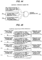
- the combustion state index calculation means 144 calculates a frequency of rotation variation occurrences and a variation strength according to the effective power of the first-order differential value. Specifically, as shown in FIG. 25, when an effective power occurrence flag (first-order differential) is 1, the combustion state index calculation means 144 performs calculation to set a combustion count and variation strength update flag (first-order differential), and calculates a combustion count (first-order differential) and variation strength (first-order differential). These calculations are performed by a method as illustrated in FIG. 49. When the effective power occurrence flag (first-order differential) is 1 and the number of effective power occurrences (first-order differential) is 3 or more, the combustion count and variation strength (first-order differential) update flag is set to 1.
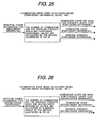
- the combustion state index calculation means 144' calculates a frequency of rotation variation occurrences and a variation strength according to the effective power of the second-order differential value. Specifically, as shown in FIG. 26, when an effective power occurrence flag (second-order differential) is 1, the combustion state index calculation means 144 performs calculation to set a combustion count and variation strength update flag (second-order differential), and calculates a combustion count (second-order differential) and variation strength (second-order differential). These calculations are performed in the same way as in the case of the first-order differential value illustrated in FIG. 49. When the effective power occurrence flag (second-order differential) is 1 and the number of effective power occurrences (second-order differential) is 3 or more, the combustion count and variation strength (second-order differential) update flag is set to 1.
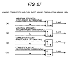
- the basic combustion air-fuel ratio value calculation means 145 calculates a basic combustion air-fuel ratio value C_abf0 according to the above combustion state index. Specifically, as shown by (A) to (D) in FIG. 27, C_abf0 is obtained from, for example, the variation strength (first-order differential) and revolutions Ne. The reason why the revolutions Ne are referenced is that the correlation between the variation strength (first-order differential) and the combustion air-fuel ratio changes according to the revolutions Ne.
- C_abf0 may be obtained from the variation strength (second-order differential) and the revolutions Ne
- C_abf0 may be obtained from the variation strength (second-order differential) and the revolutions Ne
- C_abf0 may be obtained from the combustion count (second-order differential) and the revolutions Ne.
- the largest (lean value) of the C_abf0 values may be selected.
- the combustion air-fuel ratio estimation means 150 and 150' calculate the combustion air-fuel ratio C_abf according to the above basic combustion air-fuel ratio value. Specifically, as shown in FIG. 28 (combustion air-fuel ratio estimation means 150), when the difference between the basic combustion air-fuel ratio value C_abf0 and the exhaust air-fuel ratio E_abf is equal to or greater than a prescribed value, that is, the basic combustion air-fuel ratio value C_abf0 is leaner than the exhaust air-fuel ratio E_abf by the prescribed value or more, the value of the exhaust air-fuel ratio E_abf is determined to have no validity due to, for example, the effect by unburned fuel and the basic combustion air-fuel ratio value C_abf0 is regarded as the combustion air-fuel ratio C_abf.
- the value of the exhaust air-fuel ratio E_abf is determined to have validity and the exhaust air-fuel ratio E_abf is regarded as the combustion air-fuel ratio C_abf.
- the combustion air-fuel ratio C_abf may be obtained by a method as illustrated in FIG. 29 (combustion air-fuel ratio estimation means 150'). Specifically, when the difference between the basic combustion air-fuel ratio value C_abf0 and the exhaust air-fuel ratio E_abf is equal to or greater than the prescribed value, a value obtained by adding an exhaust air-fuel ratio correction value E_abf_hos to the exhaust air-fuel ratio E_abf is regarded as the combustion air-fuel ratio C_abf.
- the value of the exhaust air-fuel ratio E_abf is determined to have no validity due to, for example, the effect by unburned fuel.
- the exhaust air-fuel ratio E_abf is then corrected and the corrected value is regarded as the combustion air-fuel ratio C_abf.
- the value used for correction is obtained from the basic combustion air-fuel ratio value C_abf0, which is considered to be a more accurately detected combustion air-fuel ratio.
- the value of the exhaust air-fuel ratio E_abf is determined to have validity and the exhaust air-fuel ratio E_abf is regarded as the combustion air-fuel ratio C_abf, as in FIG. 28.
- a variation in rotation is detected to handle it as the combustion state having a correlation to the combustion air-fuel ratio
- an intra-cylinder is detected to handle it as the combustion state having a correlation to the combustion air-fuel ratio, in this example.
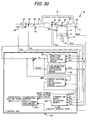
- FIG. 30 shows a system indicating a controller 1B in this example.
- the controller 1B shown in the drawing is the same as in the first example, but the intra-cylinder pressure sensor 56 rather than the revolutions sensor 37 is used to detect the combustion state. That is, the detected value Pcyl (intra-cylinder pressure profile) of the intra-cylinder pressure sensor 56 instead of the revolutions sensor 37 is used to detect the combustion state (the basic combustion air-fuel ratio value is calculated). Furthermore, a supply air-fuel ratio calculation means 260 for calculating the supply air-fuel ratio is added.
- the description that follows focuses on means having structural functions different from the first example. Although being assigned a different reference numeral, each means having the same name as in the previous example has almost the same structural function, so its explanation is simplified or omitted. The means having structural functions different from the previous example will be mainly described below.
- the supply air-fuel ratio calculation means 260 calculates the supply air-fuel ratio. Specifically, as shown in FIG. 31, the ratio of the basic amount Tp of fuel to be injected (the amount of fuel to be injected equivalent to the theoretical air-fuel ratio) to the amount Ti of fuel actually injected is multiplied by a value of 14.6 equivalent to the theoretical air-fuel ratio, and the resulting value is used as the supply air-fuel ratio S_abf.
- FIG. 32 shows the combustion state detection means 240.
- the combustion state detection means 240 comprises a combustion state detection permission means 241, an indicated mean effective pressure calculation means 242, and a basic combustion air-fuel ratio value calculation means 245.
- the combustion state detection permission means 241 determines whether to calculate the basic combustion air-fuel ratio value from the intra-cylinder pressure profile Pcyl. When detection is permitted, the combustion state detection permission flag is set to 1; when not permitted (denied), the flag is set to 0.
- the indicated mean effective pressure calculation means 242 calculates an indicated mean effective pressure Pi from the intra-cylinder pressure profile Pcyl. The method of calculating the indicated mean effective pressure from the intra-cylinder pressure profile is well-known, so it is not described here in detail. However, the indicated mean effective pressure should be obtained by performing rotation synchronous sampling at as high a speed as possible.
- the basic combustion air-fuel ratio value calculation means 245 calculates the basic combustion air-fuel ratio value C_abf0 from the indicated mean effective pressure Pi (details will be described below).
- the basic combustion air-fuel ratio value calculation means 245 calculates the basic combustion air-fuel ratio value. Specifically, it obtains a reference indicated mean effective pressure Pi0 from the basic amount Tp of fuel to be injected, as shown in FIG. 33. Although the combustion air-fuel ratio C_abf0 is obtained from the ratio between the indicated mean effective pressure Pi and the reference indicated mean effective pressure Pi0, the supply air-fuel ratio S_abf is also referenced during the obtaining process. A general characteristic of the indicated mean effective pressure with respect to the combustion air-fuel ratio tends to show an upward convex with a pressure near the stoichiometry maximized if the ignition timing is constant. Accordingly, it is discriminated in advance whether the combustion air-fuel ratio is on the rich side or lean side with respect to the stoichiometry, according to the value of the supply air-fuel ratio.
- the indicated mean effective pressure is used to obtain the basic combustion air-fuel ratio value in this example, the maximum intra-cylinder pressure within one cycle may be used.
- an intra-cylinder pressure is detected to handle it as the combustion state having a correlation to the combustion air-fuel ratio in the second example
- an intra-cylinder temperature is detected to handle it as the combustion state having a correlation to the combustion air-fuel ratio in a third example.
- FIG. 34 shows a system indicating a controller 1C in the third example.
- the controller 1C shown in the drawing is the same as in the second example, but the intra-cylinder temperature sensor 57 rather than the intra-cylinder pressure sensor 56 is used to detect the combustion state. That is, the value Tcyl detected by the intra-cylinder temperature sensor 57 instead of the intra-cylinder pressure sensor 56 is used to detect the combustion state (the basic combustion air-fuel ratio value is calculated).
- each means having the same name as in the previous examples has almost the same structural function, so its explanation is simplified or omitted. The means having structural functions different from the previous examples will be mainly described below.
- FIG. 35 shows the combustion state detection means 340.
- the combustion state detection means 340 comprises a combustion state detection permission means 341 and a basic combustion air-fuel ratio value calculation means 345.
- the combustion state detection permission means 341 determines whether to calculate the basic combustion air-fuel ratio value from the intra-cylinder temperature profile Tcyl. When detection is permitted, the combustion state detection permission flag is set to 1.
- the basic combustion air-fuel ratio value calculation means 345 calculates the basic combustion air-fuel ratio value C_abf0 from the intra-cylinder temperature profile Tcyl (details will be described below).
- the basic combustion air-fuel ratio value calculation means 345 calculates the basic combustion air-fuel ratio value. Specifically, as shown in FIG. 36, it obtains a reference intra-cylinder temperature Tcyl0 from the basic amount Tp of fuel to be injected. Although the combustion air-fuel ratio C_abf0 is obtained from the ratio between a mean intra-cylinder temperature Tcyl_m in one cycle and the reference intra-cylinder temperature Tcy10, the supply air-fuel ratio S_abf is also referenced during the obtaining process.
- a general characteristic of the intra-cylinder temperature with respect to the combustion air-fuel ratio tends to show an upward convex with a temperature near the stoichiometry maximized if the ignition timing is constant. Accordingly, it can be discriminated in advance whether the combustion air-fuel ratio is on the rich side or lean side with respect to the stoichiometry, according to the value of the supply air-fuel ratio.
- the mean intra-cylinder temperature within one cycle is used to obtain the basic combustion air-fuel ratio value in this example, the maximum intra-cylinder temperature within one cycle may be used.
- a variation in rotation, an intra-cylinder pressure, and an intra-cylinder temperature are respectively detected to handle them as the combustion state having a correlation to the combustion air-fuel ratio, and the exhaust air-fuel ratio is also used to estimate or calculate the combustion air-fuel ratio.
- the estimated combustion air-fuel ratio is used to calculate an engine control parameter (the amount of fuel to be injected in this example).
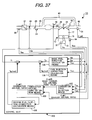
- FIG. 37 shows a system indicating a controller 1D in the fourth example.
- the controller 1D shown in the drawing is the same as in the first example, but a second fuel injection correction calculation means for calculating the amount Tp_hos2 of fuel injection correction by use of the combustion air-fuel ratio C_abf is added.
- a second fuel injection correction calculation means for calculating the amount Tp_hos2 of fuel injection correction by use of the combustion air-fuel ratio C_abf is added.
- the second fuel injection correction calculation means 430 calculates the amount Tp_hos2 of fuel injection correction by use of the combustion air-fuel ratio C_abf. Specifically, as shown in FIG. 38, the second fuel injection correction calculation means 430 obtains Tp_hos2 from the combustion air-fuel ratio C_abf with reference to a map or the like. As with the second fuel injection correction calculation means 430' shown in FIG. 39, a PI control unit may be used to calculate the amount Tp_hos2 of fuel injection correction from a difference between a target air-fuel ratio Tg_abf and the combustion air-fuel ratio C_abf. A map setting and a setting in the PI control unit may be obtained on the basis of experience in test using actual vehicles.
- the combustion air-fuel ratio is obtained from a value detected by the revolutions sensor 37
- the combustion air-fuel ratio may be estimated from the intra-cylinder pressure or intra-cylinder temperature described in the second and third examples.
- the estimated combustion air-fuel ratio is used to calculate an engine control parameter (the amount of fuel to be injected).
- the estimated combustion air-fuel ratio is used to operate a parameter for exhaust air-fuel ratio feedback control.
- FIG. 40 shows a system indicating a controller 1E in the fifth example.
- the controller 1E shown in the drawing has a structure similar to the structure in the fourth example, but an exhaust air-fuel ratio feedback control means 570 is added instead of the second fuel injection correction calculation means 430.
- the combustion air-fuel ratio C_abf is input to the exhaust air-fuel ratio feedback control means 570.
- each means having the same name as in the previous examples has almost the same structural function, so its explanation is simplified or omitted.
- the means having structural functions different from the previous examples will be mainly described below.
- the exhaust air-fuel ratio feedback control means 570 obtains the amount Tp_hos2 of fuel correction based on the exhaust air-fuel ratio E_abf. Specifically, as shown in FIG. 41, a PI control unit is used to obtain the amount Tp_hos2 of fuel injection correction from a difference between the exhaust air-fuel ratio E_abf and a target air-fuel ratio Tg_abf. However, when the difference between the combustion air-fuel ratio C_abf and the exhaust air-fuel ratio E_abf is equal to or greater than a prescribed value, the value of the exhaust air-fuel ratio E_abf is determined to have no validity and Tp_host2 is set to 1, stopping the feedback control based on the exhaust air-fuel ratio E_abf.
- the combustion air-fuel ratio is obtained on the basis of the detection by the revolutions sensor 37, it may be estimated from the intra-cylinder pressure or intra-cylinder temperature described in the second and third examples.
- This example discloses a method of learning the relation between the combustion state and the combustion air-fuel ratio in an online manner.
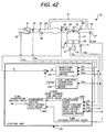
- FIG. 42 shows a system indicating a controller 1F in a sixth example.
- the combustion state detection means 140 in the first example in FIG. 18 is replaced with a combustion state detection and basic combustion air-fuel ratio value learning means 640.
- each means having the same name as in the previous examples has almost the same structural function, so its explanation is simplified or omitted.
- the means having structural functions different from the previous examples will be mainly described below.
- a learning permission means 646 and a learning value calculation means 647 are added to the combustion state detection means 140 (FIG. 21) in the first example; the calculation result given by the learning value calculation means 647 is entered into a basic combustion air-fuel ratio value calculation means 645. More specifically, when the learning permission flag f_gakusyuu_kyoka is 1, online learning of the relation between the combustion state and the combustion air-fuel ratio is permitted.
- the learning value calculation means 647 learns the relation between the exhaust air-fuel ratio E_abf and the combustion state index, which typifies the combustion state.
- the learning permission means 646 determines whether to permit online learning of the relation between the combustion state and the combustion air-fuel ratio. Specifically, as shown in FIG. 44, when cycles after the start are equal to or more than a prescribed value Cycle_sidou1, a cooling water temperature Twn is within a prescribed range, and an intake temperature Twa is within a prescribed range, the learning permission flag f_gakusuu_kyoka is set to 1, permitting the learning. In other cases, the learning permission flag f_gakusuu_kyoka is set to 0, inhibiting the learning.
- the above conditions are valid when there is no error between the combustion air-fuel ratio and the exhaust air-fuel ratio or such error, if any, is sufficiently small.
- the exhaust air-fuel ratio E_abf is then regarded as the combustion air-fuel ratio, and the relation between the combustion state (such as the strength of the variation), and the exhaust air-fuel ratio E_abf at that time is learned as the relation between the combustion state and the basic combustion air-fuel ratio value.
- the learning value calculation means 647 calculates a learning value. Specifically, as shown by (A) to (D) in FIG. 45, for example, E_abf is stored in a learning map grid that is determined by the number of combustions (first-order differential) (i) and the number of revolutions (Ne) (j) as a learning value CNT_dd_time_e_gak (i, j); the learning value learns the relation between the number of combustions (first differential), which is an combustion state index, and the basic combustion air-fuel ratio value C_abf0.
- combustion count learning value (second-order differential), variation strength learning value (first-order differential), and variation strength learning value (second-order differential) are also calculated in a similar way, as illustrated in the drawing.
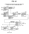
- the basic combustion air-fuel ratio value calculation means 645 calculates the basic combustion air-fuel ratio value C_abf0 according to combustion state indexes. Specifically, as shown in FIG. 46, functions for reflecting the above learning values are added to the basic combustion air-fuel ratio value calculation means 145 (shown in FIG. 27) in the first example.
- the learning value CNT_dd_time_e_gak (i, j) for the number of combustions (first-order differential) is a value within the reference map area (i, j) in FIG. 46.
- combustion air-fuel ratio is based on the detection by the revolutions sensor 37
- combustion state indexes may be calculated from the intra-cylinder pressure or intra-cylinder temperature described in the second and third examples for the learning.
- This example discloses a method of estimating a state (vaporization rate) of the fuel to be used from the supply air-fuel ratio, combustion air-fuel ratio, and exhaust air-fuel ratio.
- the example is based on the method in the second example.
- FIG. 47 shows a system indicating a controller 1G in the seventh example.
- a fuel state estimation means 780 is added to the second example in FIG. 30.
- the fuel state estimation means 780 detects a fuel state by comparing the supply air-fuel ratio, combustion air-fuel ratio, and exhaust air-fuel ratio in an area in which the fuel vaporization rate is relatively low due to, for example, a low engine temperature and an effect by a difference in fuel state is thereby produced with ease.
- each means having the same name as in the previous examples has almost the same structural function, so its explanation is simplified or omitted.
- the means having structural functions different from the previous examples will be mainly described below.
- the fuel state estimation means 780 estimates the state of the fuel to be used. Specifically, as shown in FIG. 48, when the combustion state detection permission flag is 1, the fuel state estimation means 780 calculates the fuel state index from a difference between the supply air-fuel ratio S_abf and the combustion air-fuel ratio C_abf and a difference between the combustion air-fuel ratio C_abf and the exhaust air-fuel ratio E_abf, with reference to a map. That is, the characteristics of the air-fuel ratio transmission system are largely affected by the fuel state (fuel vaporization rate).
- the fuel state estimation means 780 detects a fuel state by comparing the supply air-fuel ratio, combustion air-fuel ratio, and exhaust air-fuel ratio in an area in which the fuel vaporization rate is relatively low due to, for example, a low engine temperature and an effect by a difference in fuel state is thereby produced with ease.
- the combustion state detection permission flag is 0, the previous fuel state index value is maintained.
- the basic combustion air-fuel ratio value is obtained from the indicated mean effective pressure
- the maximum intra-cylinder pressure in one cycle may be used.
- the basic combustion air-fuel ratio value may be obtained from the variation in rotation or the intra-cylinder temperature described in the first and third examples may be used.
Abstract
Description
- The present invention relates to an engine controller that controls the amount of fuel to be injected (air-fuel ratio) and other factors and, more particularly, to a controller for a robust engine that can efficiently prevents air-flow ratio precision from being worsened at the time of start.
- In response to the recent enhanced exhaust emission control for automobiles in North America, Europe, Japan, and other countries, the improvement of engine exhaust emission characteristics is being strongly demanded. As the performance and control precision of catalysts are being improved, exhaust emission from engines is dominant when they are started. Highly precious air-fuel ratio control is also effective in improving the engine exhaust emission characteristics at the time of start. However, exhaust air-fuel ratio feedback control, in which an exhaust air-fuel ratio is detected and the amount of fuel to be injected is then corrected, is usually started at a fixed time (10 to 20 seconds) after the start.
- An air-fuel ratio sensor is activated at an early stage and a preheat system is introduced, so there is the prospect that exhaust air-fuel ratio feedback control initiated at the start will be put into practical use. When the fuel vaporization rate is low because, for example, temperature is low or heavy fuel is used, fuel that entered the combustion chamber is exhausted into the exhaust path without being burned. The exhausted fuel is oxidized in the exhaust path and by an exhaust air-fuel ratio sensor probe. When this happens, the exhaust air-fuel ratio is higher than the actual combustion air-fuel ratio. If the exhaust air-fuel ratio is fed back and the amount of fuel is determined according to the feedback, the combustion air-fuel ratio is not properly controlled (the combustion does not approach stoichiometric combustion) and an excessively lean burn thereby occurs, lowering exhaust purifying performance and running operation. To avoid this situation, a technology for initiating the detection of the combustion air-fuel ratio with high precision at the time of start and controlling the combustion air-fuel ratio is necessary.
- Accordingly, various control methods and apparatuses have been proposed as in Japanese Patent Laid-open
No. 2003-83133 Japanese Patent Laid-open No. 10-30537 -
Patent Document 1 discloses a control method in which when the temperature at the start is low, a lower fuel correction limit is restricted according to exhaust air-fuel ratio feedback from an exhaust air-fuel ratio sensor so as to prevent an excessively lean burn from occurring. In this type of control method, however, the air-fuel ratio is just prevented from being excessively leaned; the combustion air-fuel ratio cannot be controlled to an appropriate air-fuel ratio. The lower limit is determined according to a particular fuel state. Accordingly, when the lower limit is determined for a soft fuel, for example, the possibility of a lean firemiss is increased; when the lower limit is determined for a heavy fuel, the control range for leaning a soft fuel is more restrictive than necessary. - Patent Document 2 discloses another control method in which a response characteristic until the amount of fuel to be corrected on the basis of air-fuel ratio feedback is reflected in combustion is detected for each cylinder according to a rotational variation so as to appropriately correct the ignition timing. In this type of control method, however, the ignition timing is just controlled by estimating a responsiveness from fuel ignition up to the control of the combustion exhaust air-fuel ratio, so the control method does not correct a difference between the exhaust air-fuel ratio and the combustion air-fuel ratio, nor does it control the combustion air-fuel ratio. Accordingly, the control method does not addresses the problems described above.
- It is the most preferable to directly detect the combustion air-fuel ratio in the combustion chamber. However, there is large unevenness in the distribution of the air-fuel ratio in the cylinder, so a measurement at a single point does not yield high precision. An air-fuel ratio sensor needs to be attached for each cylinder, resulting in a high cost.
- The present invention addresses the above problems with the object of providing an inexpensive engine controller that can control the combustion air-fuel ratio at the time of start with high precision.
- To achieve the above object, an engine controller in a first aspect of the present invention comprises a combustion state detection or estimation means for detecting or estimating a combustion state in the combustion chamber and/or a combustion air-fuel ratio estimation means for estimating a combustion air-fuel ratio in the combustion chamber according to an exhaust air-fuel ratio and/or the detected or estimated combustion state (see FIG.1).
- As described above, for example, even when the exhaust air-fuel ratio becomes richer than the combustion air-fuel ratio due to the effect of the unburned fuel in the exhaust, the combustion state corresponds to the combustion air-fuel ratio. Accordingly, a means for detecting or estimating a combustion state is provided so as to monitor the validity of the exhaust air-fuel ratio and detect or estimate a more accurate combustion state with reference to the exhaust air-fuel ratio. It is preferable to directly detect the combustion air-fuel ratio to detect or estimate the combustion state. As described above, however, the unevenness of the intra-cylinder air-fuel ratio distribution is large, the precision in single-point measurement is poor, and an air-fuel ratio sensor required for each cylinder increases the cost, so air-fuel ratio sensors are not necessarily used and average information about combustion, such as, for example, an indicated mean effective pressure, rotational variations, and a combustion temperature is more preferable than the air-fuel ratio sensors.
- An engine controller in a second aspect of the present invention has a means for calculating an engine control parameter according to the estimated combustion air-fuel ratio (see FIG. 2).
- That is, since the engine is controlled according to the combustion air-fuel ratio, engine control performance is prevented from being worsened when an incorrect exhaust air-fuel ratio is detected as well as the engine control performance is improved.
- In an engine controller in a third aspect of the present invention, the combustion state detection or estimation means estimates the combustion state according to engine revolutions or an nth-order differential value (n: integer) of the engine revolutions (see FIG. 3).
- That is, the combustion state is detected or estimated according to variations in engine revolutions. In particular, when the first-order differential value, second-order differential value, and so on are used, the combustion state (variations in combustion) can be detected more precisely.
- In an engine controller in a fourth aspect of the present invention, the combustion state detection or estimation means estimates the combustion state according to at least one of an intra-cylinder pressure, an intra-cylinder temperature, and a generated torque in the engine (see FIG. 3).
- That is, the combustion state is stipulated as the intra-cylinder pressure (combustion pressure), intra-cylinder temperature, and generated torque in the engine. Although none of these factors are detected in a dimension of the air-fuel ratio, they are physical quantities correlated to the combustion air-fuel ratio. The combustion air-fuel ratio is highly precisely detected or estimated from the detected values and the exhaust air-fuel ratio.
- In an engine controller in a fifth aspect of the present invention, an exhaust sensor for sensing the exhaust air-fuel ratio is provided in an exhaust path (see FIG. 3).
- That is, the exhaust air-fuel ratio is stipulated as being detected by the exhaust sensor provided in the exhaust path. The exhaust sensor may be, for example, an O2 sensor, an NOx sensor, or the like.
- In an engine controller in a sixth aspect of the present invention, the combustion state detection or estimation means calculates a basic combustion air-fuel ratio value from the combustion state and the combustion air-fuel ratio estimation means estimates the combustion air-fuel ratio according to the basic combustion air-fuel ratio value and the exhaust air-fuel ratio (see FIG. 4).
- That is, the combustion state is converted to a parameter correlated to the combustion air-fuel ratio and the combustion air-fuel ratio is obtained from the basic combustion air-fuel ratio value and exhaust air-fuel ratio.
- In an engine controller in a seventh aspect of the present invention, the combustion air-fuel ratio estimation means compares the basic combustion air-fuel ratio value with the exhaust air-fuel ratio and estimates either the basic combustion air-fuel ratio value or the exhaust air-fuel ratio as the combustion air-fuel ratio according to a comparison result (see FIG. 5).
- In an engine controller in an eighth aspect of the present invention, the combustion air-fuel ratio estimation means estimates the larger of the basic combustion air-fuel ratio value and the exhaust air-fuel ratio as the combustion air-fuel ratio (see FIG. 5).
- That is, when, for example, the exhaust air-fuel ratio becomes richer than the combustion air-fuel ratio due to the effect of the unburned fuel in the exhaust, the basic combustion air-fuel ratio value becomes leaner, that is, larger, than the exhaust air-fuel ratio. The basic combustion air-fuel ratio value is then used as the combustion air-fuel ratio.
- In an engine controller in a ninth aspect of the present invention, the combustion air-fuel ratio estimation means calculates the amount of exhaust air-fuel ratio correction according to the combustion state and estimates a value obtained by correcting the exhaust air-fuel ratio with the calculated amount of exhaust air-fuel ratio correction as a combustion air-fuel ratio (see FIG. 6).
- That is, error in the exhaust air-fuel ratio is corrected according to the estimated combustion state, and the corrected exhaust air-fuel ratio is used as the combustion air-fuel ratio.
- In an engine controller in a tenth aspect of the present invention, the control parameter calculation means calculates at least one of the amount of fuel to be injected, an ignition timing, and the amount of air to be inhaled as the control parameter (see FIG. 7).
- That is, targets to be controlled are stipulated as the amount of fuel to be injected, the ignition timing, and the amount of air to be inhaled.
- An engine controller in an eleventh aspect of the present invention has a control parameter calculation permission means that permits or denies control parameter calculation, which is performed by the control parameter calculation means on the basis of the combustion air-fuel ratio, according to the running state of the engine (see FIG. 8).
- That is, as described above, error in detection of the exhaust air-fuel ratio is likely to occur, particularly at a low temperature; accordingly, engine control parameter calculation based on the combustion air-fuel ratio is performed according to the engine running state, for example, only at a low temperature.
- In an engine controller in a twelfth aspect of the present invention, the control parameter calculation permission means permits or denies the control parameter calculation according to an engine cooling water temperature, an inhaled air temperature, a time elapsed from the time of start, the total number of cycles after the start, the total amount of air inhaled after the start, and other parameters that typify an engine temperature. That is, as described above, error in detection of the exhaust air-fuel ratio is likely to occur, particularly at a low temperature; accordingly, whether to perform the engine control parameter calculation based on the combustion air-fuel ratio is determined according to the values of the above parameters that typify an engine temperature for detecting a low-temperature condition.
- In an engine controller in a thirteenth aspect of the present invention, the control parameter calculation permission means permits the engine control parameter calculation on the basis of the combustion air-fuel ratio when at least one of the following conditions is met: the engine cooling water temperature is equal to or lower than a prescribed value, the temperature of air to be inhaled into the engine is equal to or lower than a prescribed value, the time elapsed after the start of the engine is equal to or less than a prescribed value, the total number of cycles after the start of the engine is equal to or smaller than a prescribed value, and the total amount of air inhaled after the start of the engine is equal to or smaller than a prescribed value.
- That is, as described in the eleventh and twelfth aspects, a low-temperature condition under which error in exhaust air-fuel ratio detection is likely to occur is detected by the above parameters that typify an engine temperature; engine control parameter calculation based on the combustion air-fuel ratio is performed only when appropriate conditions are met.
- In an engine controller in a fourteenth aspect of the present invention, the control parameter calculation permission means has the control parameter calculation means correct engine control parameters on the basis of the exhaust air-fuel ratio or deny the engine control parameter calculation, when a difference or a ratio between the combustion air-fuel ratio and the exhaust air-fuel ratio is equal to or greater than a prescribed value (see FIG. 9).
- That is, when the difference between the exhaust air-fuel ratio and the combustion air-fuel ratio is large, the credibility of the detected exhaust air-fuel ratio value is determined to be extremely low, stopping control in which the exhaust air-fuel ratio is used.
- In an engine controller in a fifteenth aspect of the present invention, a control parameter for controlling the amount of fuel is corrected according to a fed-back exhaust air-fuel ratio, or feedback control is stopped.
- That is, the controller described in the fourteenth aspect is called exhaust air-fuel ratio feedback control by which the exhaust air-fuel ratio is fed back so as to control the amount of fuel.
- An engine controller in a sixteenth aspect of the present invention has a means for learning the relation between the combustion state and the basic combustion air-fuel ratio value according to the exhaust air-fuel ratio (see FIG. 10).
- That is, the exhaust air-fuel ratio is used to learn the relation between the combustion state and the basic combustion air-fuel ratio value. More specifically, under a running condition in which there is no error between the combustion air-fuel ratio and the exhaust air-fuel ratio or the error is sufficiently small, the exhaust air-fuel ratio is regarded as the combustion air-fuel ratio and the relation between the combustion state and the exhaust air-fuel ratio at that time is learned as the relation between the combustion state and the combustion air-fuel ratio.
- In an engine controller in a seventeenth aspect of the present invention, the learning means performs the learning according to the running state of the engine (see FIG. 11).
- That is, as described in the sixteenth aspect, whether to perform the learning is determined according to the running condition of the engine.
- In an engine controller in an eighteenth aspect of the present invention, the learning means performs the learning when at least one of the following conditions is met: the engine cooling water temperature is equal to or higher than a prescribed value, the temperature of air to be inhaled into the engine is equal to or higher than a prescribed value, a time elapsed after the start of the engine is equal to or more than a prescribed value, the total number of cycles after the start of the engine is equal to or more than a prescribed value, and the total amount of air inhaled after the start of the engine is equal to or more than a prescribed value.
- That is, as described in the sixteenth and seventeenth aspects, the condition in which the engine temperature is sufficiently high, which is a running condition when there is no error between the combustion air-fuel ratio and the exhaust air-fuel ratio or the error is sufficiently small, is more specifically stipulated.
- An engine controller in a nineteenth aspect of the present invention has a means for calculating a supply air-fuel ratio according to the amount of air to be inhaled into the engine and the amount of fuel to be injected (see FIG. 12).
- That is, although the air-fuel ratio indicates a weight ratio between the amount of air and the amount of fuel, there are transmission properties in the amount of air and the amount of fuel in a process until the intake path, combustion chamber, and exhaust path are reached. In particular, in the air-fuel ratio transmission system, the effect by the transmission characteristic from fuel injection to combustion is large. In addition to the combustion air-fuel ratio, which is the air-fuel ratio in the combustion chamber, and the exhaust air-fuel ratio, which is the air-fuel ratio in the exhaust path, a means for calculating the supply air-fuel ratio, which is the air-fuel ratio in the intake path, is provided.
- In an engine controller in a twentieth aspect of the present invention, the supply air-fuel ratio, the combustion air-fuel ratio, and the exhaust air-fuel ratio are estimated or detected independently (see FIG. 13).
- That is, in addition to the estimation or detection of the exhaust air-fuel ratio and combustion air-fuel ratio described so far, a means for calculating the supply air-fuel ratio is provided separately, making online check of the air-fuel ratio transmission system more accurate.
- In an engine controller in a twenty-first aspect of the present invention, the control parameter calculation means performs engine control parameter calculation according to the supply air-fuel ratio, the combustion air-fuel ratio, and the exhaust air-fuel ratio (see FIG. 14).
- That is, the supply air-fuel ratio, combustion air-fuel ratio, and exhaust air-fuel ratio, which are typical parameters for the air-fuel ratio transmission system, are used as information from which to calculate the engine control parameters, enabling the air-fuel ratio during cold engine operation, transition, and the like to be controlled with high precision.
- An engine controller in a twenty-second aspect of the present invention has a means for estimating a fuel state according to at least one of the supply air-fuel ratio, the combustion air-fuel ratio, and the exhaust air-fuel ratio (see FIG. 15).
- That is, the characteristic of the air-fuel ratio transmission system is largely affected by the fuel vaporization rate; when, for example, the engine is cold, the fuel vaporization rate is relatively low and a difference in the fuel state is likely to cause an effect. In such an area, the supply air-fuel ratio, combustion air-fuel ratio, and exhaust air-fuel ratio are compared to detect the fuel state.
- In an engine controller in a twenty-third aspect of the present invention, the combustion air-fuel ratio estimation means, the control parameter calculation means, and the fuel state estimation means handle the air-fuel ratio in a dimension of an equivalence ratio.
- That is, when the equivalence ratio, which is proportional to the amount of fuel to be injected, is used to for calculation, the use of the air-fuel ratio is simplified and calculation error is lessened.
- In an engine controller in a twenty-fourth aspect of the present invention, even when a detected value of the exhaust air-fuel ratio differs from the combustion exhaust air-fuel ratio during the execution of feedback control according to the exhaust air-fuel ratio, the combustion air-fuel ratio is controlled to a desired air-fuel ratio.
- That is, it is stipulated that when the combustion air-fuel ratio is indirectly controlled by detecting the exhaust air-fuel ratio, if the exhaust air-fuel ratio differs from the combustion air-fuel ratio due to the effect of unburned fuel or the like, the use of the controller in the above aspect enables the combustion air-fuel ratio, which is the original purpose, to be controlled to a desired air-fuel ratio.
- According to the present invention, the air-fuel ratio at the start of an engine can be controlled with high precision in an inexpensive manner. As a result, the exhaust emission characteristic at a cold engine start can be improved and high stability can be obtained.
- The above features and/or aspects can be combined in any way partly or as a whole.
-
- FIG. 1 is used to explain a controller in a first aspect of the present invention.
- FIG. 2 is used to explain a controller in a second aspect of the present invention.
- FIG. 3 is used to explain a controller in third to fifth aspects of the present invention.
- FIG. 4 is used to explain a controller in a sixth aspect of the present invention.
- FIG. 5 is used to explain a controller in seventh and eights aspects of the present invention.
- FIG. 6 is used to explain a controller in a ninth aspect of the present invention.
- FIG. 7 is used to explain a controller in a tenth aspect of the present invention.
- FIG. 8 is used to explain a controller in eleventh to thirteenth aspects of the present invention.
- FIG. 9 is used to explain a controller in fourteenth and fifteenth aspects of the present invention.
- FIG. 10 is used to explain a controller in a sixteenth aspect of the present invention.
- FIG. 11 is used to explain a controller in seventeenth and eighteenth aspects of the present invention.
- FIG. 12 is used to explain a controller in a nineteenth aspect of the present invention.
- FIG. 13 is used to explain a controller in a twentieth aspect of the present invention.
- FIG. 14 is used to explain a controller in a twenty-first aspect of the present invention.
- FIG. 15 is used to explain a controller in a twenty-second aspect of the present invention.
- FIG. 16 schematically shows an engine to which an embodiment of the controller according to the present invention is applied.
- FIG. 17 shows the internal structure of the control unit shown in FIG. 16.
- FIG. 18 shows a control system in a first example.
- FIG. 19 is used to explain the basic fuel injection calculation means shown in FIG. 18.
- FIG. 20 is used to explain the fuel injection correction calculation means shown in FIG. 18.
- FIG. 21 is used to explain the combustion state detection means shown in FIG. 18.
- FIG. 22 is used to explain the first-order and second-order differential value calculation means shown in FIG. 21.
- FIG. 23 is used to explain the combustion state detection permission means shown in FIG. 21.
- FIG. 24 is used to explain the effective power calculation means shown in FIG. 21.
- FIG. 25 is used to explain the combustion state index calculation means (first-order differential value) shown in FIG. 21.
- FIG. 26 is used to explain the combustion state index calculation means (second-order differential value) shown in FIG. 21.
- FIG. 27 is used to explain the basic combustion air-fuel ratio value calculation means in the combustion state detection means shown in FIG. 21.
- FIG. 28 is used to explain an example of the combustion air-fuel ratio estimation means shown in FIG. 18.
- FIG. 29 is used to explain another example of the combustion air-fuel ratio estimation means shown in FIG. 18.
- FIG. 30 shows a control system in a second example.
- FIG. 31 is used to explain the supply air-fuel ratio calculation means shown in FIG. 30.
- FIG. 32 is used to explain the combustion state detection means shown in FIG. 30.
- FIG. 33 is used to explain the basic combustion air-fuel ratio value calculation means shown in FIG. 32.
- FIG. 34 shows a control system in a third example.
- FIG. 35 is used to explain the combustion state detection means shown in FIG. 34.
- FIG. 36 is used to explain the basic combustion air-fuel ratio value calculation means shown in FIG. 35.
- FIG. 37 shows a control system in a fourth example.
- FIG. 38 shows an example of the second fuel injection correction calculation means shown in FIG. 37.
- FIG. 39 shows another example of the second fuel injection correction calculation means shown in FIG. 37.
- FIG. 40 shows a control system in a fifth example.
- FIG. 41 is used to explain the exhaust air-fuel ratio feedback control means shown in FIG. 40.
- FIG. 42 shows a control system in a sixth example.
- FIG. 43 is used to explain the combustion state detection and basic combustion air-fuel ratio value learning means shown in FIG. 42.
- FIG. 44 is used to explain the learning permission means shown in FIG. 43.
- FIG. 45 is used to explain the learning value calculation means shown in FIG. 43.
- FIG. 46 is used to explain the basic combustion air-fuel ratio value calculation means shown in FIG. 43.
- FIG. 47 shows a control system in a seventh example.
- FIG. 48 shows the fuel state estimation means shown in FIG. 47.
- FIG. 49 is used to explain the combustion state index calculation means (first-order differential value) shown in FIG. 25.
- An embodiment of an engine controller according to the present invention will be described with reference to the drawings.
- FIG. 16 schematically shows the embodiment (common to first to seventh examples) of the inventive engine controller together with a vehicle-mounted engine to which the embodiment is applied.
- The
engine 10 shown in the drawing is a multicylinder engine having, for example, fourcylinders 1 to 4. Theengine 10 has acylinder assembly 12, which comprisescylinders 1 to 4, into each of which apiston 15 is slidably fitted. Acombustion chamber 17 is formed above each of thepistons 15. An ignition plug 35 protrudes into thecombustion chamber 17 of each of thecylinders 1 to 4. - Air supplied for the combustion of fuel is inhaled from an
air cleaner 21 provided at the upstream end of anintake path 20, passes through anair flow sensor 24 and an electronicallycontroller throttle valve 25, and then enters acollector 27. The air is inhaled from thecollector 27 through anintake valve 28 disposed at a downstream end of theintake path 20 into thecombustion chambers 17 of thecylinders 1 to 4. Afuel injection valve 30 is provided downstream (intake port) of theintake path 20. - A mixture of the air inhaled into the
combustion chamber 17 and the fuel injected from thefuel injection valve 30 undergoes combustion by spark ignition by theignition plug 35. A waste gas (exhaust) resulting from the combustion is exhausted from thecombustion chamber 17 through anexhaust valve 48 into anindividual path 40A forming an upstream part of anexhaust path 40. The gas then passes from theindividual path 40A through anexhaust collector 40B and enters a three-way catalyst 50, in which the gas is purified, the three-way catalyst 50 being provided in theexhaust path 40. The purified gas is exhausted into the outside. - An
oxygen sensor 52 is provided downstream of the three-way catalyst 50 in theexhaust path 40, and an air-fuel ratio sensor 51 is provided as an exhaust sensor for sensing the exhaust air-fuel ratio in theexhaust collector 40B disposed upstream of thecatalyst 50 in theexhaust path 40. - The air-
fuel ratio sensor 51 has a linear output characteristic with respect to the density of the oxygen included in the exhaust. The relation between the oxygen density in the exhaust and the air-fuel ratio is approximately linear. Therefore, it is possible to obtain the exhaust air-fuel ratio in theexhaust collector 40B from the air-fuel ratio sensor 51 for detecting the oxygen density. Acontrol unit 100 described below obtains the exhaust air-fuel ratio upstream of the three-way catalyst 50 from a signal from the air-fuel ratio sensor 51. Thecontrol unit 100 also obtains the oxygen density downstream of the three-way catalyst 50 from theoxygen sensor 52, or determines whether the air-fuel ratio is rich or lean compared with the stoichiometry. The outputs from the air-fuel ratio sensor 51 andoxygen sensor 52 are used to perform F/B control in which the amount of fuel to be injected or the amount of air is corrected successively so that the purifying efficiency of the three-way catalyst 50 is optimized. - Part of the exhaust gas ejected from the
combustion chamber 17 to theexhaust path 40 is brought into theintake path 20 through an exhaust gas recirculation (EGR)path 41 and then returned to thecombustion chamber 17 of each cylinder through a branch path of theintake path 20, as necessary. AnEGR valve 42 for adjusting an EGR ratio is provided in theEGR path 41. - A
controller 1 in this embodiment has acontrol unit 100 incorporating a microprocessor so as to perform various types of control for theengine 10. - Basically, the
control unit 100 comprises aCPU 101, aninput circuit 102, an input/output port 103, aRAM 104, and aROM 105, as shown in FIG. 17. - Input signals supplied to the control unit 100 include a signal responsive to the amount of air to be inhaled, which is detected by the air flow sensor 24; a signal responsive to the opening of the throttle valve 25, which is detected by a throttle sensor; a signal indicating the rotation (engine revolutions) and phase of a crank shaft 18, which is obtained from a crank angle sensor (revolutions sensor) 37 (the crank angle sensor 37 outputs a signal pulse at intervals of, for example, one degree of rotational angle); a signal indicating the oxygen density downstream of the three-way catalyst 50 or determining whether the air-fuel ratio is rich or lean compared with the stoichiometry, which is obtained from the oxygen sensor 52 disposed downstream of the three-way catalyst 50 in the exhaust path 40; a signal responsive to the oxygen density (air-fuel ratio) detected by the air-fuel ratio sensor 51 disposed in the exhaust collector 40B upstream of the three-way catalyst 50 in the exhaust path 40; a signal responsive to an engine cooling water temperature detected by a water temperature sensor 19 attached to the cylinder 12; a signal responsive to the amount of depression of an accelerator pedal 39 (indicating a torque demanded by the driver), which is obtained from an accelerator sensor 36; a signal responsive to the pressure in each cylinder (in the combustion chamber 17), which is obtained from an intra-cylinder pressure sensor 56; and a signal responsive to the temperature in each cylinder (in the combustion chamber 17), which is obtained from an intra-cylinder temperature sensor 57.
- The
control unit 100 accepts outputs from the air-fuel ratio sensor 51,oxygen sensor 52, throttle sensor,air flow sensor 24, crankangle sensor 37,water temperature sensor 19,accelerator sensor 36,intra-cylinder pressure sensor 56,intra-cylinder temperature sensor 57, and so on. Thecontrol unit 100 recognizes the running state of the engine from these outputs, and calculates the amount of air to be inhaled, the amount of fuel to be injected, and an ignition timing, which are main amounts for operating the engine, according to the running state. The fuel injection amount calculated by thecontrol unit 100 is converted to an open valve pulse signal and the converted signal is sent from a fuel injectionvalve driving circuit 117 to thefuel injection valve 30. A driving signal is sent from anignition output circuit 116 to theignition plug 35 so that ignition occurs at the ignition timing calculated by thecontrol unit 100. - More specifically, in the
control unit 100, signal processing such as noise removal is performed in theinput circuit 102, and then the processed signals are sent to the input/output port 103. The values received by the input port are stored in theRAM 104 and theCPU 101 performs calculation on these values. A control program in which the calculation processing is coded is prewritten to theROM 105. Values calculated according to the control program, each of which represents the amount of actuator operation, are stored in theRAM 104 and then output to theoutput port 103. - As the driving signal for the
ignition plug 35, an on/off signal is set, the signal being in the on state while the primary coil in theignition output circuit 116 is energized and in the off state while not energized. Ignition occurs when the on state changes to the off state. The signal set in theoutput port 103 for theignition plug 35 is amplified to energy sufficient for ignition in theignition output circuit 116, and then supplied to theignition plug 35. As the driving signal (open valve pulse signal) for thefuel injection valve 30, an on/off signal is set, the signal being turned on when the valve is opened and turned off when the valve is closed. The on/off signal is amplified to energy sufficient to open thefuel injection valve 30 in the fuel injectionvalve driving circuit 117, and then supplied to thefuel injection valve 30. A driving signal for achieving a target opening of the electronicallycontroller throttle valve 25 is sent through the electronically controllerthrottle driving circuit 118 to the electronicallycontroller throttle valve 25. - Next, the processing executed by the
control unit 100 will be specifically described. - FIG. 18 shows a control system indicating a
controller 1A in a first example. Thecontroller 1A comprises a basic fuel injection calculation means 120, a fuel injection correction calculation means 130, a combustion state detection means 140, and a combustion air-fuel ratio estimation means 150. The amount Ti of fuel to be injected is calculated by multiplying the basic amount Tp of fuel to be injected by Tp_hos1 obtained from calculation by the fuel injection correction calculation means 130, so that the combustion air-fuel ratios of all cylinders become desired air-fuel ratios. The value of Tp_hos1 calculated by the fuel injection correction calculation means 130 is such that the combustion air-fuel ratio becomes the desired air-fuel ratio (near the stoichiometry), particularly in an area in which the fuel vaporization rate at the time of start is low. The combustion state detection means 140 calculates a basic combustion air-fuel ratio value from a variation in rotation. The combustion air-fuel ratio estimation means 150 calculates the combustion air-fuel ratio from the basic combustion air-fuel ratio value and exhaust air-fuel ratio. - The basic fuel injection calculation means 120, fuel injection correction calculation means 130, combustion state detection means 140, and combustion air-fuel ratio estimation means 150 will be described below in detail.
- The basic fuel injection calculation means 120 calculates the amount of fuel to be injected that achieves a target torque and target air-fuel ratio at the same time in an arbitrary running condition, according to the amount of air to be inhaled into the engine. Specifically, as shown in FIG. 18, the basic fuel injection amount Tp is calculated. Cyl indicates the number of cylinders, which is 6 in this example. K is determined according to the specifications (the relation between the fuel injection pulse width and the amount of fuel to be injected) of the fuel injection valve (injector) 30.
- The fuel injection correction calculation means 130 calculates the amount Tp_hos1 of fuel injection to be corrected. Particularly, the calculation is performed so that the combustion air-fuel ratio becomes the desired air-fuel ratio (near the stoichiometry) in an area in which the fuel vaporization rate at the time of start is low. Specifically, as shown in FIG. 20, the calculation is performed according to the time elapsed from the start time and the water temperature at the start time. Since Tp_hos1 is calculated so as to compensate the fuel vaporization rate, its initial value is determined depending on the water temperature at the start time and gradually decreases with the time elapsed.
- FIG. 21 shows the combustion state detection means 140. The combustion state detection means 140 comprises a combustion state detection permission means 141, a first-order and second-order differential value calculation means 142, an effective power calculation means 143, a combustion state index calculation means 144, and a basic combustion air-fuel ratio value calculation means 145. The combustion state detection permission means 141 determines whether to detect the combustion state from the variation in rotation. The first-order and second-order differential value calculation means 142 calculates first-order and second-order differential values of time ΔT120 taken between pulses at intervals of 120 degrees. In practice, since the calculation is performed by a microprocessor, differences are taken. When a combustion state detection permission flag is 1, prescribed processing is performed on the first-order and second-order differential values, and an effective power, combustion state index, and basic combustion air-fuel ratio value are calculated in that order.
- Processing on each block will be described below in detail.
- The first-order and second-order differential value calculation means 142 calculates first-order and second-order differential values of time ΔT120 taken between pulses at intervals of 120 degrees. Specifically, in practice, since the calculation is performed by a microprocessor, differences are taken, as shown in FIG. 22.
- The combustion state detection permission means 141 performs operations to set the combustion state detection permission flag. Specifically, as shown in FIG. 23, the combustion state detection permission means 141 sets the combustion state detection permission flag to 1 to detect the combustion state when cycles after the start are equal to or more than a prescribed value Cycle_sidou0, a cooling water temperature Twn(k) is within a prescribed range, and an intake temperature Twa(k) is within a prescribed range. If any of these conditions is not met, detection of the combustion state is not permitted, setting the combustion state detection permission flag to 0. The value of Cycle_sidou0 is preferably determined according to the performance of the engine. A value is preferably set according to the purpose, for example, to detect the combustion state from a first explosion, after the completion of an explosion, or after peak revolutions are reached. This is also true for the cooling water temperature and intake temperature. To detect an effect by the fuel state, a value is preferably set within an area in which there is a difference in the fuel vaporization rate, as shown in example 7.
- The effective power calculation means 143 calculates effective power for a positive first-order differential value and effective power for a negative second-order differential value, as shown in FIG. 24.
- When the combustion state detection permission flag is 1 and the first-order differential value is equal to or greater than a prescribed value, an effective power generation flag (first-order differential) is set to 1 and the difference between the first-order differential value and a prescribed value is taken as effective power (first differential). When the combustion state detection permission flag is 1 and the second-order differential value is equal to or smaller than a prescribed value, another effective power generation flag (second-order differential) is set to 1 and the difference between the second-order differential value and a prescribed value is taken as effective power (second differential).
- Each time this processing is initiated after the combustion state detection permission flag is set to 1, the total number of combustions after the combustion state detection permission is calculated by incrementing the total number of combustions after the detection permission by one.
- Although the effective power is obtained from a difference (relative value) from a threshold, an absolute value may be used.
- The combustion state index calculation means 144 calculates a frequency of rotation variation occurrences and a variation strength according to the effective power of the first-order differential value. Specifically, as shown in FIG. 25, when an effective power occurrence flag (first-order differential) is 1, the combustion state index calculation means 144 performs calculation to set a combustion count and variation strength update flag (first-order differential), and calculates a combustion count (first-order differential) and variation strength (first-order differential). These calculations are performed by a method as illustrated in FIG. 49. When the effective power occurrence flag (first-order differential) is 1 and the number of effective power occurrences (first-order differential) is 3 or more, the combustion count and variation strength (first-order differential) update flag is set to 1.
- The combustion state index calculation means 144' calculates a frequency of rotation variation occurrences and a variation strength according to the effective power of the second-order differential value. Specifically, as shown in FIG. 26, when an effective power occurrence flag (second-order differential) is 1, the combustion state index calculation means 144 performs calculation to set a combustion count and variation strength update flag (second-order differential), and calculates a combustion count (second-order differential) and variation strength (second-order differential). These calculations are performed in the same way as in the case of the first-order differential value illustrated in FIG. 49. When the effective power occurrence flag (second-order differential) is 1 and the number of effective power occurrences (second-order differential) is 3 or more, the combustion count and variation strength (second-order differential) update flag is set to 1.
- The basic combustion air-fuel ratio value calculation means 145 calculates a basic combustion air-fuel ratio value C_abf0 according to the above combustion state index. Specifically, as shown by (A) to (D) in FIG. 27, C_abf0 is obtained from, for example, the variation strength (first-order differential) and revolutions Ne. The reason why the revolutions Ne are referenced is that the correlation between the variation strength (first-order differential) and the combustion air-fuel ratio changes according to the revolutions Ne. Alternatively, C_abf0 may be obtained from the variation strength (second-order differential) and the revolutions Ne, C_abf0 may be obtained from the variation strength (second-order differential) and the revolutions Ne, or C_abf0 may be obtained from the combustion count (second-order differential) and the revolutions Ne. The largest (lean value) of the C_abf0 values may be selected.
- The combustion air-fuel ratio estimation means 150 and 150' calculate the combustion air-fuel ratio C_abf according to the above basic combustion air-fuel ratio value. Specifically, as shown in FIG. 28 (combustion air-fuel ratio estimation means 150), when the difference between the basic combustion air-fuel ratio value C_abf0 and the exhaust air-fuel ratio E_abf is equal to or greater than a prescribed value, that is, the basic combustion air-fuel ratio value C_abf0 is leaner than the exhaust air-fuel ratio E_abf by the prescribed value or more, the value of the exhaust air-fuel ratio E_abf is determined to have no validity due to, for example, the effect by unburned fuel and the basic combustion air-fuel ratio value C_abf0 is regarded as the combustion air-fuel ratio C_abf. When the difference between the basic combustion air-fuel ratio value C_abf0 and the exhaust air-fuel ratio E_abf is smaller than the prescribed value, the value of the exhaust air-fuel ratio E_abf is determined to have validity and the exhaust air-fuel ratio E_abf is regarded as the combustion air-fuel ratio C_abf.
- Alternatively, the combustion air-fuel ratio C_abf may be obtained by a method as illustrated in FIG. 29 (combustion air-fuel ratio estimation means 150'). Specifically, when the difference between the basic combustion air-fuel ratio value C_abf0 and the exhaust air-fuel ratio E_abf is equal to or greater than the prescribed value, a value obtained by adding an exhaust air-fuel ratio correction value E_abf_hos to the exhaust air-fuel ratio E_abf is regarded as the combustion air-fuel ratio C_abf. That is, when the basic combustion air-fuel ratio value C_abf0 is leaner than the exhaust air-fuel ratio E_abf by the prescribed value or more, the value of the exhaust air-fuel ratio E_abf is determined to have no validity due to, for example, the effect by unburned fuel. The exhaust air-fuel ratio E_abf is then corrected and the corrected value is regarded as the combustion air-fuel ratio C_abf. The value used for correction is obtained from the basic combustion air-fuel ratio value C_abf0, which is considered to be a more accurately detected combustion air-fuel ratio.
- When the difference between the basic combustion air-fuel ratio value C_abf0 and the exhaust air-fuel ratio E_abf is smaller than the prescribed value, the value of the exhaust air-fuel ratio E_abf is determined to have validity and the exhaust air-fuel ratio E_abf is regarded as the combustion air-fuel ratio C_abf, as in FIG. 28.
- Although, in the first example, a variation in rotation is detected to handle it as the combustion state having a correlation to the combustion air-fuel ratio, an intra-cylinder is detected to handle it as the combustion state having a correlation to the combustion air-fuel ratio, in this example.
- FIG. 30 shows a system indicating a
controller 1B in this example. Basically, thecontroller 1B shown in the drawing is the same as in the first example, but theintra-cylinder pressure sensor 56 rather than therevolutions sensor 37 is used to detect the combustion state. That is, the detected value Pcyl (intra-cylinder pressure profile) of theintra-cylinder pressure sensor 56 instead of therevolutions sensor 37 is used to detect the combustion state (the basic combustion air-fuel ratio value is calculated). Furthermore, a supply air-fuel ratio calculation means 260 for calculating the supply air-fuel ratio is added. The description that follows focuses on means having structural functions different from the first example. Although being assigned a different reference numeral, each means having the same name as in the previous example has almost the same structural function, so its explanation is simplified or omitted. The means having structural functions different from the previous example will be mainly described below. - The supply air-fuel ratio calculation means 260 calculates the supply air-fuel ratio. Specifically, as shown in FIG. 31, the ratio of the basic amount Tp of fuel to be injected (the amount of fuel to be injected equivalent to the theoretical air-fuel ratio) to the amount Ti of fuel actually injected is multiplied by a value of 14.6 equivalent to the theoretical air-fuel ratio, and the resulting value is used as the supply air-fuel ratio S_abf.
- FIG. 32 shows the combustion state detection means 240. The combustion state detection means 240 comprises a combustion state detection permission means 241, an indicated mean effective pressure calculation means 242, and a basic combustion air-fuel ratio value calculation means 245.
- The combustion state detection permission means 241 determines whether to calculate the basic combustion air-fuel ratio value from the intra-cylinder pressure profile Pcyl. When detection is permitted, the combustion state detection permission flag is set to 1; when not permitted (denied), the flag is set to 0. The indicated mean effective pressure calculation means 242 calculates an indicated mean effective pressure Pi from the intra-cylinder pressure profile Pcyl. The method of calculating the indicated mean effective pressure from the intra-cylinder pressure profile is well-known, so it is not described here in detail. However, the indicated mean effective pressure should be obtained by performing rotation synchronous sampling at as high a speed as possible. The basic combustion air-fuel ratio value calculation means 245 calculates the basic combustion air-fuel ratio value C_abf0 from the indicated mean effective pressure Pi (details will be described below).
- The basic combustion air-fuel ratio value calculation means 245 calculates the basic combustion air-fuel ratio value. Specifically, it obtains a reference indicated mean effective pressure Pi0 from the basic amount Tp of fuel to be injected, as shown in FIG. 33. Although the combustion air-fuel ratio C_abf0 is obtained from the ratio between the indicated mean effective pressure Pi and the reference indicated mean effective pressure Pi0, the supply air-fuel ratio S_abf is also referenced during the obtaining process. A general characteristic of the indicated mean effective pressure with respect to the combustion air-fuel ratio tends to show an upward convex with a pressure near the stoichiometry maximized if the ignition timing is constant. Accordingly, it is discriminated in advance whether the combustion air-fuel ratio is on the rich side or lean side with respect to the stoichiometry, according to the value of the supply air-fuel ratio.
- Although the indicated mean effective pressure is used to obtain the basic combustion air-fuel ratio value in this example, the maximum intra-cylinder pressure within one cycle may be used.
- Although a variation in rotation is detected to handle it as the combustion state having a correlation to the combustion air-fuel ratio in the first example and an intra-cylinder pressure is detected to handle it as the combustion state having a correlation to the combustion air-fuel ratio in the second example, an intra-cylinder temperature is detected to handle it as the combustion state having a correlation to the combustion air-fuel ratio in a third example.
- FIG. 34 shows a system indicating a
controller 1C in the third example. Basically, thecontroller 1C shown in the drawing is the same as in the second example, but theintra-cylinder temperature sensor 57 rather than theintra-cylinder pressure sensor 56 is used to detect the combustion state. That is, the value Tcyl detected by theintra-cylinder temperature sensor 57 instead of theintra-cylinder pressure sensor 56 is used to detect the combustion state (the basic combustion air-fuel ratio value is calculated). Although being assigned a different reference numeral, each means having the same name as in the previous examples has almost the same structural function, so its explanation is simplified or omitted. The means having structural functions different from the previous examples will be mainly described below. - FIG. 35 shows the combustion state detection means 340. The combustion state detection means 340 comprises a combustion state detection permission means 341 and a basic combustion air-fuel ratio value calculation means 345.
- The combustion state detection permission means 341 determines whether to calculate the basic combustion air-fuel ratio value from the intra-cylinder temperature profile Tcyl. When detection is permitted, the combustion state detection permission flag is set to 1. The basic combustion air-fuel ratio value calculation means 345 calculates the basic combustion air-fuel ratio value C_abf0 from the intra-cylinder temperature profile Tcyl (details will be described below).
- The basic combustion air-fuel ratio value calculation means 345 calculates the basic combustion air-fuel ratio value. Specifically, as shown in FIG. 36, it obtains a reference intra-cylinder temperature Tcyl0 from the basic amount Tp of fuel to be injected. Although the combustion air-fuel ratio C_abf0 is obtained from the ratio between a mean intra-cylinder temperature Tcyl_m in one cycle and the reference intra-cylinder temperature Tcy10, the supply air-fuel ratio S_abf is also referenced during the obtaining process. A general characteristic of the intra-cylinder temperature with respect to the combustion air-fuel ratio tends to show an upward convex with a temperature near the stoichiometry maximized if the ignition timing is constant. Accordingly, it can be discriminated in advance whether the combustion air-fuel ratio is on the rich side or lean side with respect to the stoichiometry, according to the value of the supply air-fuel ratio.
- Although the mean intra-cylinder temperature within one cycle is used to obtain the basic combustion air-fuel ratio value in this example, the maximum intra-cylinder temperature within one cycle may be used.
- In the first, second, and third examples, a variation in rotation, an intra-cylinder pressure, and an intra-cylinder temperature are respectively detected to handle them as the combustion state having a correlation to the combustion air-fuel ratio, and the exhaust air-fuel ratio is also used to estimate or calculate the combustion air-fuel ratio. In a fourth example, the estimated combustion air-fuel ratio is used to calculate an engine control parameter (the amount of fuel to be injected in this example).
- FIG. 37 shows a system indicating a
controller 1D in the fourth example. Basically, thecontroller 1D shown in the drawing is the same as in the first example, but a second fuel injection correction calculation means for calculating the amount Tp_hos2 of fuel injection correction by use of the combustion air-fuel ratio C_abf is added. Although being assigned a different reference numeral, each means having the same name as in the previous examples has almost the same structural function, so its explanation is simplified or omitted. The means having structural functions different from the previous examples will be mainly described below. - The second fuel injection correction calculation means 430 calculates the amount Tp_hos2 of fuel injection correction by use of the combustion air-fuel ratio C_abf. Specifically, as shown in FIG. 38, the second fuel injection correction calculation means 430 obtains Tp_hos2 from the combustion air-fuel ratio C_abf with reference to a map or the like. As with the second fuel injection correction calculation means 430' shown in FIG. 39, a PI control unit may be used to calculate the amount Tp_hos2 of fuel injection correction from a difference between a target air-fuel ratio Tg_abf and the combustion air-fuel ratio C_abf. A map setting and a setting in the PI control unit may be obtained on the basis of experience in test using actual vehicles.
- Although, in this example, the combustion air-fuel ratio is obtained from a value detected by the
revolutions sensor 37, the combustion air-fuel ratio may be estimated from the intra-cylinder pressure or intra-cylinder temperature described in the second and third examples. - In the method in the fourth example, the estimated combustion air-fuel ratio is used to calculate an engine control parameter (the amount of fuel to be injected). In a fifth example, the estimated combustion air-fuel ratio is used to operate a parameter for exhaust air-fuel ratio feedback control.
- FIG. 40 shows a system indicating a
controller 1E in the fifth example. Thecontroller 1E shown in the drawing has a structure similar to the structure in the fourth example, but an exhaust air-fuel ratio feedback control means 570 is added instead of the second fuel injection correction calculation means 430. To operate the parameter for exhaust air-fuel ratio feedback control by use of the combustion air-fuel ratio C_abf, the combustion air-fuel ratio C_abf is input to the exhaust air-fuel ratio feedback control means 570. Although being assigned a different reference numeral, each means having the same name as in the previous examples has almost the same structural function, so its explanation is simplified or omitted. The means having structural functions different from the previous examples will be mainly described below. - The exhaust air-fuel ratio feedback control means 570 obtains the amount Tp_hos2 of fuel correction based on the exhaust air-fuel ratio E_abf. Specifically, as shown in FIG. 41, a PI control unit is used to obtain the amount Tp_hos2 of fuel injection correction from a difference between the exhaust air-fuel ratio E_abf and a target air-fuel ratio Tg_abf. However, when the difference between the combustion air-fuel ratio C_abf and the exhaust air-fuel ratio E_abf is equal to or greater than a prescribed value, the value of the exhaust air-fuel ratio E_abf is determined to have no validity and Tp_host2 is set to 1, stopping the feedback control based on the exhaust air-fuel ratio E_abf.
- Although, in this example, the combustion air-fuel ratio is obtained on the basis of the detection by the
revolutions sensor 37, it may be estimated from the intra-cylinder pressure or intra-cylinder temperature described in the second and third examples. - This example discloses a method of learning the relation between the combustion state and the combustion air-fuel ratio in an online manner.
- FIG. 42 shows a system indicating a
controller 1F in a sixth example. In thecontroller 1F shown in the drawing, the combustion state detection means 140 in the first example in FIG. 18 is replaced with a combustion state detection and basic combustion air-fuel ratio value learning means 640. Although being assigned a different reference numeral, each means having the same name as in the previous examples has almost the same structural function, so its explanation is simplified or omitted. The means having structural functions different from the previous examples will be mainly described below. - In the combustion state detection and basic combustion air-fuel ratio value learning means 640, as shown in FIG. 43, a learning permission means 646 and a learning value calculation means 647 are added to the combustion state detection means 140 (FIG. 21) in the first example; the calculation result given by the learning value calculation means 647 is entered into a basic combustion air-fuel ratio value calculation means 645. More specifically, when the learning permission flag f_gakusyuu_kyoka is 1, online learning of the relation between the combustion state and the combustion air-fuel ratio is permitted. The learning value calculation means 647 learns the relation between the exhaust air-fuel ratio E_abf and the combustion state index, which typifies the combustion state.
- The learning permission means 646 determines whether to permit online learning of the relation between the combustion state and the combustion air-fuel ratio. Specifically, as shown in FIG. 44, when cycles after the start are equal to or more than a prescribed value Cycle_sidou1, a cooling water temperature Twn is within a prescribed range, and an intake temperature Twa is within a prescribed range, the learning permission flag f_gakusuu_kyoka is set to 1, permitting the learning. In other cases, the learning permission flag f_gakusuu_kyoka is set to 0, inhibiting the learning. The above conditions are valid when there is no error between the combustion air-fuel ratio and the exhaust air-fuel ratio or such error, if any, is sufficiently small. The exhaust air-fuel ratio E_abf is then regarded as the combustion air-fuel ratio, and the relation between the combustion state (such as the strength of the variation), and the exhaust air-fuel ratio E_abf at that time is learned as the relation between the combustion state and the basic combustion air-fuel ratio value.
- The learning value calculation means 647 calculates a learning value. Specifically, as shown by (A) to (D) in FIG. 45, for example, E_abf is stored in a learning map grid that is determined by the number of combustions (first-order differential) (i) and the number of revolutions (Ne) (j) as a learning value CNT_dd_time_e_gak (i, j); the learning value learns the relation between the number of combustions (first differential), which is an combustion state index, and the basic combustion air-fuel ratio value C_abf0.
- A combustion count learning value (second-order differential), variation strength learning value (first-order differential), and variation strength learning value (second-order differential) are also calculated in a similar way, as illustrated in the drawing.
- The basic combustion air-fuel ratio value calculation means 645 calculates the basic combustion air-fuel ratio value C_abf0 according to combustion state indexes. Specifically, as shown in FIG. 46, functions for reflecting the above learning values are added to the basic combustion air-fuel ratio value calculation means 145 (shown in FIG. 27) in the first example. The learning value CNT_dd_time_e_gak (i, j) for the number of combustions (first-order differential) is a value within the reference map area (i, j) in FIG. 46. Learning values CNT_ddd_1_time_e_gak (i, j), P_dd_time_e_gak (i, j), and P_ddd_1_time_e_gak (i, j) of other combustion state indexes, that is, the number of combustions (second-order differential), variation strength (first-order differential), and variation strength (second-order differential) are also reflected in a similar way, as shown in the drawing.
- Although, in this example, the combustion air-fuel ratio is based on the detection by the
revolutions sensor 37, combustion state indexes may be calculated from the intra-cylinder pressure or intra-cylinder temperature described in the second and third examples for the learning. - This example discloses a method of estimating a state (vaporization rate) of the fuel to be used from the supply air-fuel ratio, combustion air-fuel ratio, and exhaust air-fuel ratio. The example is based on the method in the second example.
- FIG. 47 shows a system indicating a
controller 1G in the seventh example. In thecontroller 1G in the drawing, a fuel state estimation means 780 is added to the second example in FIG. 30. The fuel state estimation means 780 detects a fuel state by comparing the supply air-fuel ratio, combustion air-fuel ratio, and exhaust air-fuel ratio in an area in which the fuel vaporization rate is relatively low due to, for example, a low engine temperature and an effect by a difference in fuel state is thereby produced with ease. Although being assigned a different reference numeral, each means having the same name as in the previous examples has almost the same structural function, so its explanation is simplified or omitted. The means having structural functions different from the previous examples will be mainly described below. - The fuel state estimation means 780 estimates the state of the fuel to be used. Specifically, as shown in FIG. 48, when the combustion state detection permission flag is 1, the fuel state estimation means 780 calculates the fuel state index from a difference between the supply air-fuel ratio S_abf and the combustion air-fuel ratio C_abf and a difference between the combustion air-fuel ratio C_abf and the exhaust air-fuel ratio E_abf, with reference to a map. That is, the characteristics of the air-fuel ratio transmission system are largely affected by the fuel state (fuel vaporization rate). Accordingly, the fuel state estimation means 780 detects a fuel state by comparing the supply air-fuel ratio, combustion air-fuel ratio, and exhaust air-fuel ratio in an area in which the fuel vaporization rate is relatively low due to, for example, a low engine temperature and an effect by a difference in fuel state is thereby produced with ease. When the combustion state detection permission flag is 0, the previous fuel state index value is maintained.
- Although, in this example, the basic combustion air-fuel ratio value is obtained from the indicated mean effective pressure, the maximum intra-cylinder pressure in one cycle may be used. Alternatively, the basic combustion air-fuel ratio value may be obtained from the variation in rotation or the intra-cylinder temperature described in the first and third examples may be used.
- The above features and embodiments can be combined in any way partly or as a whole.
Claims (24)
- An engine controller, comprising a combustion state detection or estimation means for detecting or estimating a combustion state in a combustion chamber (17) and a combustion air-fuel ratio estimation means for estimating a combustion air-fuel ratio in the combustion chamber (17) according to an exhaust air-fuel ratio and the detected or estimated combustion state.
- The engine controller according to claim 1, further comprising a means for calculating an engine control parameter according to the estimated combustion exhaust air-fuel ratio.
- The engine controller according to claim 1 or 2, wherein the combustion state detection or estimation means estimates the combustion state according to engine revolutions or an nth-order differential value (n: integer) of the engine revolutions.
- The engine controller according to at least one of claims 1 to 3, wherein the combustion state detection or estimation means estimates the combustion state according to at least one of an intra-cylinder pressure, an intracylinder temperature, and a generated torque in the engine.
- The engine controller according to at least one of claims 1 to 4, wherein an exhaust sensor (51) for sensing the exhaust air-fuel ratio is provided in an exhaust path.
- The engine controller according to at least one of claims 1 to 5, wherein the combustion state detection or estimation means calculates a basic combustion air-fuel ratio value from the combustion state and the combustion air-fuel ratio estimation means estimates the combustion air-fuel ratio according to the basic combustion air-fuel ratio value and the exhaust air-fuel ratio.
- The engine controller according to at least one of claims 1 to 6, wherein the combustion air-fuel ratio estimation means compares the basic combustion air-fuel ratio value with the exhaust air-fuel ratio and estimates either the basic combustion air-fuel ratio value or the exhaust air-fuel ratio as the combustion air-fuel ratio according to a comparison result.
- The engine controller according to at least one of claims 1 to 7, wherein the combustion air-fuel ratio estimation means estimates the larger of the basic combustion air-fuel ratio value and the exhaust air-fuel ratio as the combustion air-fuel ratio.
- The engine controller according to at least one of claims 1 to 8, wherein the combustion air-fuel ratio estimation means calculates the amount of exhaust air-fuel ratio correction according to the combustion state and estimates a value obtained by correcting the exhaust air-fuel ratio with the calculated amount of exhaust air-fuel ratio correction as a combustion air-fuel ratio.
- The engine controller according to at least one of claims 1 to 9, wherein the control parameter calculation means calculates at least one of the amount of fuel to be injected, an ignition timing, and the amount of air to be inhaled as the control parameter.
- The engine controller according to at least one of claims 1 to 10, further comprising a control parameter calculation permission means that permits or denies control parameter calculation, which is performed by the control parameter calculation means on the basis of the combustion air-fuel ratio, according to the running state of the engine.
- The engine controller according to at least one of claims 1 to 11, wherein the control parameter calculation permission means permits or denies the control parameter calculation according to an engine cooling water temperature, an inhaled air temperature, a time elapsed from the time of start, the total number of cycles after the start, the total amount of air inhaled after the start, and other parameters that typify an engine temperature.
- The engine controller according to at least one of claims 1 to 12, wherein the control parameter calculation permission means permits the engine control parameter calculation on the basis of the combustion air-fuel ratio when at least one of the following conditions is met: the engine cooling water temperature is equal to or lower than a prescribed value, the temperature of air to be inhaled into the engine is equal to or lower than a prescribed value, the time elapsed after the start of the engine is equal to or less than a prescribed value, the total number of cycles after the start of the engine is equal to or smaller than a prescribed value, and the total amount of air inhaled after the start of the engine is equal to or smaller than a prescribed value.
- The engine controller according to at least one of claims 1 to 13, wherein the control parameter calculation permission means has the control parameter calculation means correct engine control parameters on the basis of the exhaust air-fuel ratio or deny the engine control parameter calculation, when a difference or a ratio between the combustion air-fuel ratio and the exhaust air-fuel ratio is equal to or greater than a prescribed value.
- The engine controller according to at least one of claims 1 to 14, wherein the control parameter calculation means corrects a control parameter for controlling the amount of fuel according to a fed-back exhaust air-fuel ratio, or stops feedback control.
- The engine controller according to at least one of claims 1 to 15, further comprising a means for learning the relation between the combustion state and the basic combustion air-fuel ratio value according to the exhaust air-fuel ratio.
- The engine controller according to at least one of claims 1 to 16, wherein the learning means performs the learning according to the running state of the engine.
- The engine controller according to at least one of claims 1 to 17, wherein the learning means performs the learning when at least one of the following conditions is met: an engine cooling water temperature is equal to or higher than a prescribed value, the temperature of air to be inhaled into the engine is equal to or higher than a prescribed value, a time elapsed after the start of the engine is equal to or more than a prescribed value, the total number of cycles after the start of the engine is equal to or more than a prescribed value, and the total amount of air inhaled after the start of the engine is equal to or more than a prescribed value.
- The engine controller according to at least one of claims 1 to 18, further comprising a means for calculating a supply air-fuel ratio according to the amount of air to be inhaled into the engine and the amount of fuel to be injected.
- The engine controller according to at least one of claims 1 to 19, wherein the supply air-fuel ratio, the combustion air-fuel ratio, and the exhaust air-fuel ratio are estimated or detected independently.
- The engine controller according to at least one of claims 1 to 20, further comprising the control parameter calculation means for performing engine control parameter calculation according to the supply air-fuel ratio, the combustion air-fuel ratio, and the exhaust air-fuel ratio.
- The engine controller according to at least one of claims 1 to 21, further comprising a means for estimating a fuel state according to at least one of the supply air-fuel ratio, the combustion air-fuel ratio, and the exhaust air-fuel ratio.
- The engine controller according to at least one of claims 1 to 22, wherein the combustion air-fuel ratio estimation means, the control parameter calculation means, and the fuel state estimation means handle the air-fuel ratio in a dimension of an equivalence ratio.
- The engine controller according to at least one of claims 1 to 23, wherein even when a detected value of the exhaust air-fuel ratio differs from the combustion exhaust air-fuel ratio during the execution of feedback control according to the exhaust air-fuel ratio, the combustion air-fuel ratio is controlled to a desired air-fuel ratio.
Applications Claiming Priority (1)
| Application Number | Priority Date | Filing Date | Title |
|---|---|---|---|
| JP2006132056A JP4276241B2 (en) | 2006-05-11 | 2006-05-11 | Engine control device |
Publications (2)
| Publication Number | Publication Date |
|---|---|
| EP1854983A2 true EP1854983A2 (en) | 2007-11-14 |
| EP1854983A3 EP1854983A3 (en) | 2008-12-31 |
Family
ID=38370408
Family Applications (1)
| Application Number | Title | Priority Date | Filing Date |
|---|---|---|---|
| EP07008952A Withdrawn EP1854983A3 (en) | 2006-05-11 | 2007-05-03 | Engine controller |
Country Status (3)
| Country | Link |
|---|---|
| US (1) | US7650225B2 (en) |
| EP (1) | EP1854983A3 (en) |
| JP (1) | JP4276241B2 (en) |
Cited By (2)
| Publication number | Priority date | Publication date | Assignee | Title |
|---|---|---|---|---|
| CN102032058A (en) * | 2009-09-30 | 2011-04-27 | 通用汽车环球科技运作公司 | Control system and method using geometry based exhaust mixing model |
| EP3865698A1 (en) * | 2020-02-14 | 2021-08-18 | Mazda Motor Corporation | Control device for rotation output device |
Families Citing this family (32)
| Publication number | Priority date | Publication date | Assignee | Title |
|---|---|---|---|---|
| US7637248B2 (en) * | 2007-01-25 | 2009-12-29 | Andreas Stihl Ag & Co. Kg | Method for operating an internal combustion engine by determining and counteracting a pre-ignition state |
| JP2008274883A (en) * | 2007-05-01 | 2008-11-13 | Toyota Motor Corp | Control device of internal combustion engine |
| US8061216B2 (en) * | 2007-12-21 | 2011-11-22 | Bausch & Lomb Incorporated | Aspiration flow mesurement system with flow signal air bubble filter |
| JP2009167871A (en) * | 2008-01-15 | 2009-07-30 | Toyota Motor Corp | Control device of internal combustion engine |
| CN101932817B (en) * | 2008-01-29 | 2013-07-10 | 马克卡车公司 | Method for starting an engine, and an engine |
| JP4664395B2 (en) | 2008-05-23 | 2011-04-06 | 日立オートモティブシステムズ株式会社 | Engine control device |
| EP2375038B1 (en) * | 2010-04-08 | 2015-03-04 | Delphi International Operations Luxembourg S.à r.l. | Diagnosis device and method using an in-cylinder pressure sensor in an internal combustion engine |
| US8752366B2 (en) * | 2010-05-21 | 2014-06-17 | Toyota Motor Engineering & Manufacturing North America, Inc. | Systems and methods for abating carbon monoxide in an exhaust stream |
| DE102010030404A1 (en) * | 2010-06-23 | 2011-12-29 | Robert Bosch Gmbh | Method for operating an internal combustion engine |
| US9534547B2 (en) | 2012-09-13 | 2017-01-03 | GM Global Technology Operations LLC | Airflow control systems and methods |
| US9714616B2 (en) | 2014-03-26 | 2017-07-25 | GM Global Technology Operations LLC | Non-model predictive control to model predictive control transitions |
| US9765703B2 (en) | 2013-04-23 | 2017-09-19 | GM Global Technology Operations LLC | Airflow control systems and methods using model predictive control |
| US9599053B2 (en) | 2014-03-26 | 2017-03-21 | GM Global Technology Operations LLC | Model predictive control systems and methods for internal combustion engines |
| US9863345B2 (en) | 2012-11-27 | 2018-01-09 | GM Global Technology Operations LLC | System and method for adjusting weighting values assigned to errors in target actuator values of an engine when controlling the engine using model predictive control |
| US9399959B2 (en) | 2014-03-26 | 2016-07-26 | GM Global Technology Operations LLC | System and method for adjusting a torque capacity of an engine using model predictive control |
| US9784198B2 (en) | 2015-02-12 | 2017-10-10 | GM Global Technology Operations LLC | Model predictive control systems and methods for increasing computational efficiency |
| US9920697B2 (en) | 2014-03-26 | 2018-03-20 | GM Global Technology Operations LLC | Engine control systems and methods for future torque request increases |
| US9599049B2 (en) | 2014-06-19 | 2017-03-21 | GM Global Technology Operations LLC | Engine speed control systems and methods |
| US9429085B2 (en) | 2013-04-23 | 2016-08-30 | GM Global Technology Operations LLC | Airflow control systems and methods using model predictive control |
| US9797318B2 (en) | 2013-08-02 | 2017-10-24 | GM Global Technology Operations LLC | Calibration systems and methods for model predictive controllers |
| US9541019B2 (en) | 2014-03-26 | 2017-01-10 | GM Global Technology Operations LLC | Estimation systems and methods with model predictive control |
| US9587573B2 (en) | 2014-03-26 | 2017-03-07 | GM Global Technology Operations LLC | Catalyst light off transitions in a gasoline engine using model predictive control |
| US9528453B2 (en) | 2014-11-07 | 2016-12-27 | GM Global Technologies Operations LLC | Throttle control systems and methods based on pressure ratio |
| US9732688B2 (en) | 2014-03-26 | 2017-08-15 | GM Global Technology Operations LLC | System and method for increasing the temperature of a catalyst when an engine is started using model predictive control |
| US9605615B2 (en) | 2015-02-12 | 2017-03-28 | GM Global Technology Operations LLC | Model Predictive control systems and methods for increasing computational efficiency |
| US9435274B2 (en) | 2014-03-26 | 2016-09-06 | GM Global Technology Operations LLC | System and method for managing the period of a control loop for controlling an engine using model predictive control |
| DE102015104099B4 (en) * | 2014-03-26 | 2019-09-12 | GM Global Technology Operations LLC (n. d. Ges. d. Staates Delaware) | Diagnostic systems and diagnostic methods using model prediction control |
| DE202015004194U1 (en) * | 2015-06-11 | 2016-09-13 | GM Global Technology Operations LLC (n. d. Ges. d. Staates Delaware) | Computer program for operating an internal combustion engine |
| US9938908B2 (en) | 2016-06-14 | 2018-04-10 | GM Global Technology Operations LLC | System and method for predicting a pedal position based on driver behavior and controlling one or more engine actuators based on the predicted pedal position |
| DE112018004225B4 (en) * | 2017-09-21 | 2023-03-16 | Hitachi Astemo, Ltd. | Internal combustion engine control apparatus and internal combustion engine control method |
| JP6942068B2 (en) * | 2018-01-30 | 2021-09-29 | 日産自動車株式会社 | Fuel injection control method and fuel injection device for spark-ignition internal combustion engine |
| JP7225593B2 (en) * | 2018-07-26 | 2023-02-21 | マツダ株式会社 | Compression ignition engine controller |
Citations (1)
| Publication number | Priority date | Publication date | Assignee | Title |
|---|---|---|---|---|
| US20030056764A1 (en) * | 2001-09-26 | 2003-03-27 | Toyota Jidosha Kabushiki Kaisha | Control system and control method for in-cylinder injection type internal combustion engine |
Family Cites Families (21)
| Publication number | Priority date | Publication date | Assignee | Title |
|---|---|---|---|---|
| JPH05163992A (en) | 1991-12-16 | 1993-06-29 | Japan Electron Control Syst Co Ltd | Fail safe device for mixed fuel supply device |
| JPH06229969A (en) | 1992-02-13 | 1994-08-19 | Ngk Spark Plug Co Ltd | Air/fuel ratio control device and deterioration detection device of oxygen sensor |
| JP3321477B2 (en) * | 1993-04-09 | 2002-09-03 | 株式会社日立製作所 | Diagnostic device for exhaust gas purification device |
| JPH07119533A (en) | 1993-10-27 | 1995-05-09 | Unisia Jecs Corp | Combusting condition detection device for internal combustion engine |
| US5694901A (en) * | 1994-03-31 | 1997-12-09 | Mitsubishi Jidosha Kogyo Kabushiki Kaisha | Method for the determination of rough road in vehicle with internal combustion engine mounted thereon |
| JP3325162B2 (en) * | 1995-09-04 | 2002-09-17 | 株式会社日立製作所 | Device for detecting combustion state of internal combustion engine |
| JP3427626B2 (en) | 1996-07-15 | 2003-07-22 | 日産自動車株式会社 | Ignition timing control device for internal combustion engine |
| JP3477016B2 (en) * | 1997-02-19 | 2003-12-10 | 株式会社日立製作所 | Device for detecting combustion state of internal combustion engine |
| JP3855481B2 (en) * | 1998-08-12 | 2006-12-13 | 株式会社日立製作所 | Engine diagnostic equipment |
| JP3626395B2 (en) * | 2000-06-12 | 2005-03-09 | 三菱電機株式会社 | Knock control device for internal combustion engine |
| JP3467455B2 (en) * | 2000-07-17 | 2003-11-17 | 本田技研工業株式会社 | Air-fuel ratio estimator for each cylinder of internal combustion engine |
| FR2816989B1 (en) * | 2000-11-20 | 2003-05-16 | Saime Sarl | METHOD FOR OPTIMIZING THE COMBUSTION OF AN INTERNAL COMBUSTION ENGINE OPERATING IN SELF-IGNITION |
| JP3948226B2 (en) * | 2001-06-14 | 2007-07-25 | 日産自動車株式会社 | Control device and control method for internal combustion engine |
| JP3789336B2 (en) | 2001-09-14 | 2006-06-21 | 本田技研工業株式会社 | Air-fuel ratio feedback control device for internal combustion engine |
| WO2004022959A1 (en) * | 2002-09-09 | 2004-03-18 | Toyota Jidosha Kabushiki Kaisha | Control device of internal combustion engine |
| DE102004010344A1 (en) * | 2003-03-04 | 2004-10-14 | Denso Corp., Kariya | Secondary air supply control device for an internal combustion engine |
| DE10319529B3 (en) * | 2003-04-30 | 2004-07-15 | Siemens Ag | Lambda signal determination method for engine control providing lambda regulation of IC engine, has mean value obtained from different lambda actual values determined by different methods |
| FR2867232B1 (en) * | 2004-03-05 | 2006-05-05 | Inst Francais Du Petrole | METHOD OF ESTIMATING FUEL WEALTH IN A CYLINDER OF A COMBUSTION ENGINE |
| JP4179192B2 (en) * | 2004-03-08 | 2008-11-12 | 株式会社デンソー | Combustion state detection device for internal combustion engine |
| DE102004038389B4 (en) * | 2004-08-06 | 2016-11-24 | Iav Gmbh Ingenieurgesellschaft Auto Und Verkehr | Method for determining the air ratio lambda from combustion chamber variables on the basis of a lambda probe measurement in the exhaust gas |
| US7140360B2 (en) * | 2005-03-03 | 2006-11-28 | Cummins, Inc. | System for controlling exhaust emissions produced by an internal combustion engine |
-
2006
- 2006-05-11 JP JP2006132056A patent/JP4276241B2/en not_active Expired - Fee Related
-
2007
- 2007-05-03 EP EP07008952A patent/EP1854983A3/en not_active Withdrawn
- 2007-05-08 US US11/797,889 patent/US7650225B2/en active Active
Patent Citations (1)
| Publication number | Priority date | Publication date | Assignee | Title |
|---|---|---|---|---|
| US20030056764A1 (en) * | 2001-09-26 | 2003-03-27 | Toyota Jidosha Kabushiki Kaisha | Control system and control method for in-cylinder injection type internal combustion engine |
Cited By (3)
| Publication number | Priority date | Publication date | Assignee | Title |
|---|---|---|---|---|
| CN102032058A (en) * | 2009-09-30 | 2011-04-27 | 通用汽车环球科技运作公司 | Control system and method using geometry based exhaust mixing model |
| CN102032058B (en) * | 2009-09-30 | 2014-02-19 | 通用汽车环球科技运作公司 | Control system and method using geometry based exhaust mixing model |
| EP3865698A1 (en) * | 2020-02-14 | 2021-08-18 | Mazda Motor Corporation | Control device for rotation output device |
Also Published As
| Publication number | Publication date |
|---|---|
| US20070261671A1 (en) | 2007-11-15 |
| EP1854983A3 (en) | 2008-12-31 |
| US7650225B2 (en) | 2010-01-19 |
| JP2007303353A (en) | 2007-11-22 |
| JP4276241B2 (en) | 2009-06-10 |
Similar Documents
| Publication | Publication Date | Title |
|---|---|---|
| US7650225B2 (en) | Engine controller | |
| JP2884472B2 (en) | Fuel property detection device for internal combustion engine | |
| JP3578597B2 (en) | Control device for direct injection spark ignition type internal combustion engine | |
| US7448360B2 (en) | Controller of internal combustion engine | |
| JP2007120392A (en) | Air fuel ratio control device for internal combustion engine | |
| US8033267B2 (en) | Control apparatus for an engine | |
| US7178494B2 (en) | Variable valve timing controller for internal combustion engine | |
| US7574299B2 (en) | Fuel injection control apparatus and method for internal combustion engine | |
| JP3314294B2 (en) | Control device for internal combustion engine | |
| JP3467455B2 (en) | Air-fuel ratio estimator for each cylinder of internal combustion engine | |
| JP3791032B2 (en) | Fuel injection control device for internal combustion engine | |
| US20110100344A1 (en) | Vehicle and vehicle control method | |
| JP4387384B2 (en) | Control device for internal combustion engine | |
| JP4361917B2 (en) | Engine control device | |
| US6729305B2 (en) | Fuel injection amount control apparatus and method for internal combustion engine | |
| JP5310102B2 (en) | Control device for internal combustion engine | |
| JP4790787B2 (en) | Control device for internal combustion engine | |
| JP4792453B2 (en) | Intake air amount detection device | |
| US4951635A (en) | Fuel injection control system for internal combustion engine with compensation of overshooting in monitoring of engine load | |
| US20090105931A1 (en) | Controller for internal combustion engine | |
| JP2000257476A (en) | Control unit for in-cylinder injection engine | |
| JP2000073927A (en) | Burning condition detecting device for internal combustion engine | |
| JP2005201163A (en) | Control device for internal combustion engine | |
| JP3680505B2 (en) | Fuel injection control device for direct-injection spark-ignition internal combustion engine | |
| JP2010007523A (en) | Air-fuel ratio control device for engine |
Legal Events
| Date | Code | Title | Description |
|---|---|---|---|
| PUAI | Public reference made under article 153(3) epc to a published international application that has entered the european phase |
Free format text: ORIGINAL CODE: 0009012 |
|
| AK | Designated contracting states |
Kind code of ref document: A2 Designated state(s): AT BE BG CH CY CZ DE DK EE ES FI FR GB GR HU IE IS IT LI LT LU LV MC MT NL PL PT RO SE SI SK TR |
|
| AX | Request for extension of the european patent |
Extension state: AL BA HR MK YU |
|
| PUAL | Search report despatched |
Free format text: ORIGINAL CODE: 0009013 |
|
| AK | Designated contracting states |
Kind code of ref document: A3 Designated state(s): AT BE BG CH CY CZ DE DK EE ES FI FR GB GR HU IE IS IT LI LT LU LV MC MT NL PL PT RO SE SI SK TR |
|
| AX | Request for extension of the european patent |
Extension state: AL BA HR MK RS |
|
| 17P | Request for examination filed |
Effective date: 20090402 |
|
| 17Q | First examination report despatched |
Effective date: 20090526 |
|
| AKX | Designation fees paid |
Designated state(s): DE |
|
| STAA | Information on the status of an ep patent application or granted ep patent |
Free format text: STATUS: THE APPLICATION IS DEEMED TO BE WITHDRAWN |
|
| 18D | Application deemed to be withdrawn |
Effective date: 20110628 |