EP1854577B1 - Method of manufacturing column and bed of machine tool and structure thereof - Google Patents
Method of manufacturing column and bed of machine tool and structure thereof Download PDFInfo
- Publication number
- EP1854577B1 EP1854577B1 EP06405207.9A EP06405207A EP1854577B1 EP 1854577 B1 EP1854577 B1 EP 1854577B1 EP 06405207 A EP06405207 A EP 06405207A EP 1854577 B1 EP1854577 B1 EP 1854577B1
- Authority
- EP
- European Patent Office
- Prior art keywords
- bed
- side plates
- machine tool
- column
- side plate
- Prior art date
- Legal status (The legal status is an assumption and is not a legal conclusion. Google has not performed a legal analysis and makes no representation as to the accuracy of the status listed.)
- Active
Links
- 238000004519 manufacturing process Methods 0.000 title description 13
- 238000003754 machining Methods 0.000 claims description 28
- 239000002184 metal Substances 0.000 claims description 14
- 238000010276 construction Methods 0.000 description 5
- 238000000034 method Methods 0.000 description 5
- 238000003466 welding Methods 0.000 description 5
- 238000000137 annealing Methods 0.000 description 3
- 238000005520 cutting process Methods 0.000 description 3
- 239000000463 material Substances 0.000 description 3
- 239000000470 constituent Substances 0.000 description 2
- 238000010586 diagram Methods 0.000 description 2
- 239000007769 metal material Substances 0.000 description 2
- 238000003698 laser cutting Methods 0.000 description 1
- 238000011089 mechanical engineering Methods 0.000 description 1
- 230000003287 optical effect Effects 0.000 description 1
- 238000009417 prefabrication Methods 0.000 description 1
- 239000003351 stiffener Substances 0.000 description 1
Images


Classifications
-
- B—PERFORMING OPERATIONS; TRANSPORTING
- B23—MACHINE TOOLS; METAL-WORKING NOT OTHERWISE PROVIDED FOR
- B23Q—DETAILS, COMPONENTS, OR ACCESSORIES FOR MACHINE TOOLS, e.g. ARRANGEMENTS FOR COPYING OR CONTROLLING; MACHINE TOOLS IN GENERAL CHARACTERISED BY THE CONSTRUCTION OF PARTICULAR DETAILS OR COMPONENTS; COMBINATIONS OR ASSOCIATIONS OF METAL-WORKING MACHINES, NOT DIRECTED TO A PARTICULAR RESULT
- B23Q1/00—Members which are comprised in the general build-up of a form of machine, particularly relatively large fixed members
- B23Q1/01—Frames, beds, pillars or like members; Arrangement of ways
- B23Q1/015—Frames, beds, pillars
-
- B—PERFORMING OPERATIONS; TRANSPORTING
- B23—MACHINE TOOLS; METAL-WORKING NOT OTHERWISE PROVIDED FOR
- B23K—SOLDERING OR UNSOLDERING; WELDING; CLADDING OR PLATING BY SOLDERING OR WELDING; CUTTING BY APPLYING HEAT LOCALLY, e.g. FLAME CUTTING; WORKING BY LASER BEAM
- B23K26/00—Working by laser beam, e.g. welding, cutting or boring
- B23K26/36—Removing material
- B23K26/38—Removing material by boring or cutting
-
- B—PERFORMING OPERATIONS; TRANSPORTING
- B23—MACHINE TOOLS; METAL-WORKING NOT OTHERWISE PROVIDED FOR
- B23K—SOLDERING OR UNSOLDERING; WELDING; CLADDING OR PLATING BY SOLDERING OR WELDING; CUTTING BY APPLYING HEAT LOCALLY, e.g. FLAME CUTTING; WORKING BY LASER BEAM
- B23K2101/00—Articles made by soldering, welding or cutting
- B23K2101/04—Tubular or hollow articles
-
- F—MECHANICAL ENGINEERING; LIGHTING; HEATING; WEAPONS; BLASTING
- F16—ENGINEERING ELEMENTS AND UNITS; GENERAL MEASURES FOR PRODUCING AND MAINTAINING EFFECTIVE FUNCTIONING OF MACHINES OR INSTALLATIONS; THERMAL INSULATION IN GENERAL
- F16B—DEVICES FOR FASTENING OR SECURING CONSTRUCTIONAL ELEMENTS OR MACHINE PARTS TOGETHER, e.g. NAILS, BOLTS, CIRCLIPS, CLAMPS, CLIPS OR WEDGES; JOINTS OR JOINTING
- F16B5/00—Joining sheets or plates, e.g. panels, to one another or to strips or bars parallel to them
- F16B5/07—Joining sheets or plates, e.g. panels, to one another or to strips or bars parallel to them by means of multiple interengaging protrusions on the surfaces, e.g. hooks, coils
Definitions
- the present invention relates to a bed of a machine tool and a structure thereof.
- FIG. 1 is an explanatory view showing a basic structure of a machine tool.
- a machine tool indicated generally by reference numeral 1 has a saddle 20 supporting a machining head 10 capable of vertical movement, and the saddle 20 is supported by a column 30 capable of horizontal movement.
- the column 30 has a motor 40 and moves on a bed 50 in the longitudinal direction.
- the bed 50 has a construction that a pair of structures are connected to each other by a beam 60.
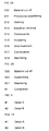
- FIG. 2A shows a conventional manufacturing process of can manufacturing constituting the bed 50 of the machine tool.
- a material is cut off in step S10.
- a dimensional tolerance is approximately ⁇ 1 mm to the fusing of 1000 mm.
- step S13 distortion generated by welding is removed.
- distortion generated by welding is removed.
- This structure is conveyed to annealing equipment in step S14 and annealed in step S15.
- a shot treatment is applied to the annealed structure, which is conveyed to machining equipment in step S17, given machining in step S18 and completed into the bed 50.
- This machining has a maximum machining range of not more than 4 m even in a relatively generally-used large-sized machine, and a place for machining is extremely limited for a large-sized work piece exceeding this size.
- Document GB 2 394 691 discloses a machine tool frame structure comprising two spaced end wall parts and two spaced, rectilinearly-elongate members bridging the space between the end wall parts.
- the elongate members are channel-form and comprise parallel, bent sheet metal members of substantially identical dimensions and cross-sectional form, which are rigid with the first and second end wall parts.
- the elongate sheet metal members are assembled with bolts and nuts 89 and by means of spot welding. These elongate members are suitable as trackways for a tool-carrying carriage of a machine tool, such as a lathe or router.
- Document DE 44 15 305 refers to a method for the production of a machine tool in which load-bearing elements and/or elements forming an outer cover of the machine tool are prefabricated and subsequently welded together during an assembly operation. Tenons and mortices are used to join the sheet metal members constituting the structure of the machine tool. Stiffeners can be added if the stiffness of the sheet metal members is itself not sufficient for the needs of the machine tool. During prefabrication at least some of the elements are cut out with the use of a laser cutting process.
- Document WO 2004/067872 discloses a framework structure made of two-dimensional or three-dimensional support structure for a machine tool, especially a laser-based machining device: It comprises several planar parts, such as ribs or plates, which can be inserted into each other as plug-in elements by means of recesses so as to form some type of grid structure. Preferably three parts are inserted into each other at least at one point of the support structure in order to form a lock.
- Document EP 1 600 242 refers to an invention providing a reflector-mirror drive shaft controller for laser beam machine which optimizes a beam for workpiece thickness by correcting a control axis of a laser reflector-mirror of a laser beam machine.
- a machine comprises, as basic means, a bed, a pallet which is disposed on the bed and holds a workpiece, and a column which moves along a longitudinal axis of the bed.
- a machining head which is supported by saddle mounted on the column, has an optical system which admits a laser beam from a laser oscillator.
- An object of the present invention is to provide a method of manufacturing a structural body such as a column and a bed of a machine tool solving the above problems and a structure produced by this manufacturing method.
- a bed of the machine tool having the assembly structure of the sheet metal member made by the laser precision machining is provided with an upper unit and a lower unit of the bed, and the lower unit of the bed is provided with side plates extending in the longitudinal direction of the bed and oppositely arranged, a bottom plate covering a bottom portion of the side plates, a rectangular column member arranged on an upper part of the side plates, end face plates covering both ends of the side plates, a plurality of ribs arranged inside and joined to the side plates and a fastening unit for fastening both the side plates.
- a bed of a machine tool which is a large-sized structure, can be constructed easily by assembling sheet metal material.
- such a large-sized structure can be manufactured in 3 to 4 days.
- FIG. 2B is an explanatory diagram showing a manufacturing process of a bed.
- step S20 a sheet metal material is cut off to make a required member.
- Laser precision machining is used as cutting means.
- the laser precision machining has a dimensional tolerance with a high accuracy of ⁇ 0.05 mm with respect to a cut length of 1000 mm.
- step S21 a machined member to be assembled to the bed is machined.
- step S22 the bed 50 is completed by assembling a sheet metal member and assembling the machined member.
- the sheet metal member is machined with a high accuracy including a tenon and a mortice, and by assembling these members, a structure such as a column or a bed can be manufactured easily. Since a fastening member such as a bolt/nut is used for fastening of members, large-scale welding or annealing is not needed. Then, welding distortion or the like is not generated but a structure with a high accuracy can be obtained.
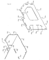
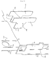
- FIG. 3 is a perspective view showing an entire construction of a column made by the manufacturing method of the present invention.
- a column unit generally referred to as reference character 30A is provided with a column body 100 and column foot members 200 mounted at both side ends of the column body 100.
- FIG. 4 is a perspective view of the column body 100, and the column body 100 has a front member 110, a rear member 130 and side covers 140 mounted on both side ends.
- FIG. 5 is an exploded view of the column body
- FIG. 6 is a detailed view of A part in FIG. 5
- FIG. 7 is a detailed view of B part in FIG. 5 .
- the column body has the front member 110 obtained by folding machining of a plate member and applying a required machining such as a slit and the rear member 130 given the same machining, and two types of ribs 150, 160 are arranged inside a closed sectional space formed by the front member 110 and the rear member 130. And both side ends of the column body are covered by the side covers 140.
- FIG. 6 is an explanatory view showing an engagement structure between the column body rear member 130 and the side cover 140
- FIG. 7 is an explanatory view showing an engagement structure between the column body front member 120, the rib 160 and the side cover 140.
- a plurality of projection portions 130a, 130b, 130c, 130d, 130e, 130j, 130k and so on to be tenons are provided.
- a plurality of slits 140a, 140b, 140c, 140d, 140e, 140m, 140n, 140p, 140q, 140r and so on to be mortices and recess portions 140j, 140k, 140l are formed.
- the projection portion 130a of the rear member 130 is inserted into the slit 140a of the side cover 140 and fixed.
- each of the projection portions 130b, 130c, 130d, 130e of the rear member 130 is inserted into the slits 140b, 140c, 140d, 140e of the side cover 140 and fixed.
- the projection portions 130j, 130k of the rear member 130 are engaged with the recess portions 140j, 140k of the side cover 140.
- the rear member 130 has slits 130f, 130g, 130h into which a projection portion of the rib 160 is inserted, which will be described referring to FIG. 7 .
- the front member 120 has a plurality of projection portions 120m, 120n, 120p, 120q, 120r, 1201 on the end, while slits 120a, 120b, 120c, 120d and so on are formed on a face plate portion.
- the projection portions 120m, 120n, 120p, 120q, 120r on the end are inserted and fixed to the corresponding slits 140m, 140n, 140p, 140q, 140r on the side cover 140 as described referring to FIG. 6 .
- the rib 160 is provided with a plurality of projection portions 160a, 160b, 160c, 160d, 160e, 160f, 160g, 160h on its outer edge portion.
- the projection portions 160a, 160b, 160c, 160d of the rib 160 are inserted and fixed to the corresponding slits 120a, 120b, 120c, 120d of the front member 120, respectively.
- the projection portion 160e on the bottom portion of the rib 160 is inserted into a slit, not shown, formed on the bottom portion of the front member 120 and fixed.
- the projection portions 160f, 160g, 160h of the rib 160 are inserted and fixed to the corresponding slits 130f, 130g, 130h of the rear member 130.
- the column body is assembled by the above-mentioned fastening structure.
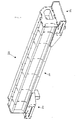
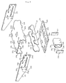
- FIG. 8 is a perspective view of the column foot member 200
- FIG. 9 is an exploded view of the column foot member.
- the column foot member generally referred to as reference numeral 200 has a foot body 210, a bottom plate 220, a body cover 230, two types of ribs 240, 250, a stopper 260 and a stopper cover 270.
- each member constituting the column foot member is made by precision laser machining of a sheet metal and by folding required portions.
- the foot body 210 has projection portions 210a, 210b, 210c, 210d, 210e, 210f, 210g on both sides and has recess portions 210h, 210k, 2101 at a bent lower end.
- slits 210m, 210n, 210p, 210q, 210r, 210s are formed.
- the bottom plate 220 has projection portions 220h, 220k, 220l to be engaged with corresponding recess portions 210h, 210k, 2101 of the body 210.
- the body cover 230 has a plurality of slits 230a, 230b, 230c, 230d, 230e, 230f, 230g and so on formed.
- the projection portions 210a, 210b, 210c, 210d, 210e, 210f, 210g of the foot body 210 are inserted into the corresponding slits 230a, 230b, 230c, 230d, 230e, 230f, 230g of the body cover 230, respectively.
- the rib 240 has projection portions 240m, 240n, 240p on an upper part, and each of the projection portions is inserted into the corresponding slits 210m, 210n, 210p of the foot body 210.
- the projection portions 240m, 240n, 240p pierce the upper surface of the foot body 210 and project upward.
- the rib 250 has projection portions 250q, 250r, 250s on an upper part, which are inserted into the corresponding slits 210q, 210r, 210s of the foot body 210.
- the stopper 260 is folded in a rectangular column shape, and a plurality of projection portions 260a, 260b and so on are provided at an end.
- the stopper cover 270 has corresponding recess portions 270a, 270b and so on, and the stopper covers 270 are engaged with both sides of the stopper 260.
- the column of the present invention has the above-described construction, and the entire unit is assembled by preparing sheet metal members made by precision laser machining and inserting projection portions provided at required locations into the slits.
- the constituent members are all sheet metal members, and machining can be automated and required units can be produced in a short time.
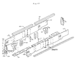
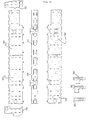
- FIG. 10 is a perspective view of a bed unit.
- the bed unit generally referred to as reference character 50A is constituted by a bed lower portion 300 and a bed upper portion 600.
- FIG. 11 shows an assembly structure of the bed lower unit 300 and the bed upper portion 600 and an assembling procedure to complete the bed unit by assembling upper can machining members 610, 620 after completion of the bed lower unit 300.
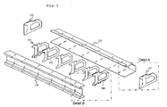
- FIG. 12 is an assembled view of the bed lower unit 300
- FIG. 13 is an exploded view.
- the bed lower unit 300 has four side plates 310, 320, 330, 340 and bottom plates 360, 362 and is provided with ribs 370, 372, 380, 390, 392, 400 and so on having various shapes for connecting these side plates to the bottom plates.
- FIG. 14 shows a detail of A part of FIG. 13
- FIG. 15 shows a detail of B part.
- the two side plates 310 and 320 are constituted into a single side plate unit by combining a joint structure using a dovetail tenon 310a formed at each of the ends and a dovetail tenon groove 320a.
- the side plate unit is assembled and constituted by two side plates, there is no need to use a large-sized laser machine for machining of each side plate and productivity and machining accuracy are improved.
- the side plate 330 and the side plate 340 are also constituted into a single side plate unit by combining a dovetail tenon 330a and a dovetail tenon groove 340a.
- FIG. 14 shows a joint structure of the side plate 330 and the side plate 340.
- Three dovetail tenons 330a, 330b, 330c are provided at an end of the side plate 330.
- three dovetail tenon grooves 340a, 340b, 340c are formed at an end of the side plate 340.
- the two side plates are assembled into a single side plate unit.
- the side plate unit 330 has slits 330d, 330e, 330f and so on to which the projection portions of the rib are inserted and the side plate unit 330 is provided with square holes 330g, 330h, 330j, 330k and so on for attaching a fastening unit, which will be described later.
- the side plate 340 is also provided with slits 340d, 340e, 340f and so on to which the projection portions of the rib are inserted and a square hole 340g and so on for attaching the fastening unit.
- the bottom plate 362 also has slits 362a, 362b, 362c, 362d to which the projection portions formed at a lower part of the side plate are inserted and a slit 362e to which the projection portion of the rib is inserted.
- a plurality of projection portions are provided at the end of the side plate 310, and a projection portion 310c is inserted into a corresponding slit 350c of an end side plate 350.
- a projection portion 330d at the end of the side plate 330 shown in FIG. 13 is inserted.
- a pair of ribs 370, 372 have flange portions 370a, 372d and pierce the slits 310a, 310d of the side plate 310 and project. These flange portions 370a, 372d are used for mounting a lateral beam connecting the right and left bed units.
- One rib 370 has a square hole 370b for the fastening unit, while the other rib 372 has a circular hole 372b for bolt piercing.
- FIG. 16 shows a list of laser machined members of the members constituting the bed lower unit.
- FIG. 17 shows a sectional structure of the bed.
- the opposing side plates 310, 330 are joined by the rib 370 and fastened by a fastening unit 500.
- the fastening unit 500 is constituted by a pipe 510, a bolt 520 inserted into the pipe 510 and a nut 530.
- the pipe 510 is pressed into contact with inner wall portions of the two side plates 310, 330.
- the bolt 520 has a round head portion 524, a square column portion 522 formed at a seated portion immediately below the round head portion 524 and a screw portion 526.
- a rectangular column shaped member 450 is disposed at upper parts of the opposing side plates 310, 330 and joined by the fastening unit 500.
- a plurality of ribs are disposed inside the two side plates 310, 330. Moreover, a projection portion provided at a lower end of the side plate is inserted into a slit of a base plate.
- the mechanism for improving the rigidity has highly accurate projection portions (tenons) and slits (mortices) machined with a dimensional accuracy of about 0.05 to 0.1 mm by laser machining and constitutes a highly rigid integral structure by fastening a large number of highly accurate constituent members machined with a dimensional accuracy of about 0.05 to 0.01 mm by a laser machine with a large number of projection portions and slits arranged at random as well as a large number of fastening bolts or the like so as to offset dimensional tolerance and to integrally assemble those elements.
Description
- The present invention relates to a bed of a machine tool and a structure thereof.
-
FIG. 1 is an explanatory view showing a basic structure of a machine tool. - A machine tool indicated generally by
reference numeral 1 has asaddle 20 supporting amachining head 10 capable of vertical movement, and thesaddle 20 is supported by acolumn 30 capable of horizontal movement. - The
column 30 has amotor 40 and moves on abed 50 in the longitudinal direction. Thebed 50 has a construction that a pair of structures are connected to each other by a beam 60. -
FIG. 2A shows a conventional manufacturing process of can manufacturing constituting thebed 50 of the machine tool. - A material is cut off in step S10. When plasma fusing is used as means for cutting, for example, a dimensional tolerance is approximately ±1 mm to the fusing of 1000 mm.
- The cut off material is provisionally assembled in step S11 and welded in step S12. In step S13, distortion generated by welding is removed. For example, in a lengthy structure with the whole length of approximately 8 m, distortion of not less than 10 mm is normally generated. Moreover, the distortion removal is a work requiring a long time labor by a worker with an extremely advanced skill. This structure is conveyed to annealing equipment in step S14 and annealed in step S15. A shot treatment is applied to the annealed structure, which is conveyed to machining equipment in step S17, given machining in step S18 and completed into the
bed 50. This machining has a maximum machining range of not more than 4 m even in a relatively generally-used large-sized machine, and a place for machining is extremely limited for a large-sized work piece exceeding this size. - Construction of a machine tool in a welding can manufacturing structure is disclosed in non-patent documents of "Design Principle of Machine Tool" (1971) written by F. Koenigsberger, translated by Susumu Shiozaki and published by Yokendo and a magazine, "Applied Mechanical Engineering," Special Feature: Welded Structure Design, issued on March 1, 1970, Vol. 11, No. 3.
-
Document GB 2 394 691 - Document
DE 44 15 305 refers to a method for the production of a machine tool in which load-bearing elements and/or elements forming an outer cover of the machine tool are prefabricated and subsequently welded together during an assembly operation. Tenons and mortices are used to join the sheet metal members constituting the structure of the machine tool. Stiffeners can be added if the stiffness of the sheet metal members is itself not sufficient for the needs of the machine tool. During prefabrication at least some of the elements are cut out with the use of a laser cutting process. - Document
WO 2004/067872 discloses a framework structure made of two-dimensional or three-dimensional support structure for a machine tool, especially a laser-based machining device: It comprises several planar parts, such as ribs or plates, which can be inserted into each other as plug-in elements by means of recesses so as to form some type of grid structure. Preferably three parts are inserted into each other at least at one point of the support structure in order to form a lock. -
Document EP 1 600 242 refers to an invention providing a reflector-mirror drive shaft controller for laser beam machine which optimizes a beam for workpiece thickness by correcting a control axis of a laser reflector-mirror of a laser beam machine. Such a machine comprises, as basic means, a bed, a pallet which is disposed on the bed and holds a workpiece, and a column which moves along a longitudinal axis of the bed. A machining head, which is supported by saddle mounted on the column, has an optical system which admits a laser beam from a laser oscillator. - Since a bed or the like of a machine tool is a large-sized structure, conveyance requires labor, and equipment such as a large-sized annealing furnace is needed.
- Also, equipment for machining needs a large-sized machine and the number of processes becomes huge. Production time takes a couple of months or more using a conventional process.
- An object of the present invention is to provide a method of manufacturing a structural body such as a column and a bed of a machine tool solving the above problems and a structure produced by this manufacturing method.
- A bed of the machine tool having the assembly structure of the sheet metal member made by the laser precision machining is provided with an upper unit and a lower unit of the bed, and the lower unit of the bed is provided with side plates extending in the longitudinal direction of the bed and oppositely arranged, a bottom plate covering a bottom portion of the side plates, a rectangular column member arranged on an upper part of the side plates, end face plates covering both ends of the side plates, a plurality of ribs arranged inside and joined to the side plates and a fastening unit for fastening both the side plates.
- According to the present invention, a bed of a machine tool, which is a large-sized structure, can be constructed easily by assembling sheet metal material.
- Manufacture of the bed with this assembly structure of the sheet metal members is completed by achieving high accuracy of laser machining.
- According to the present invention, such a large-sized structure can be manufactured in 3 to 4 days.
-
-
FIG. 1 is an explanatory view showing a basic structure of a machine tool; -
FIG. 2 is a diagram showing a manufacturing process of a bed of the machine tool; -
FIG. 3 is an assembled view of a column of the present invention; -
FIG. 4 is an assembled view of a body of the column of the present invention; -
FIG. 5 is an exploded view of the body of the column of the present invention; -
FIG. 6 is a detailed view of A part ofFIG. 5 ; -
FIG. 7 is a detailed view of B part ofFIG. 5 ; -
FIG. 8 is an assembled view of a column foot member; -
FIG. 9 is an exploded view of the column foot member; -
FIG. 10 is an assembled view of a bed of the present invention; -
FIG. 11 is an explanatory view of an upper member and a lower member of the bed of the present invention; -
FIG. 12 is an assembled view of a bed lower unit; -
FIG. 13 is an exploded view of the bed lower unit; -
FIG. 14 is a detailed view of A part ofFIG. 13 ; -
FIG. 15 is a detailed view of B part ofFIG. 13 ; -
FIG. 16 is a list view of laser machining members of the bed lower unit; and -
FIG. 17 is a sectional view of the bed lower unit. -
FIG. 2B is an explanatory diagram showing a manufacturing process of a bed. - In step S20, a sheet metal material is cut off to make a required member. Laser precision machining is used as cutting means. The laser precision machining has a dimensional tolerance with a high accuracy of ±0.05 mm with respect to a cut length of 1000 mm. In parallel with this material cutting process, in step S21, a machined member to be assembled to the bed is machined.
- In step S22, the
bed 50 is completed by assembling a sheet metal member and assembling the machined member. - As mentioned above, according to the present invention, since the laser precision machining can be used, the sheet metal member is machined with a high accuracy including a tenon and a mortice, and by assembling these members, a structure such as a column or a bed can be manufactured easily. Since a fastening member such as a bolt/nut is used for fastening of members, large-scale welding or annealing is not needed. Then, welding distortion or the like is not generated but a structure with a high accuracy can be obtained.
- Moreover, since machining can be performed in parallel with laser precision machining, productivity is high and required structures can be manufactured in a short period of time.
- A structure and a manufacturing method of a column and a bed according to the present invention will be described below.
-
FIG. 3 is a perspective view showing an entire construction of a column made by the manufacturing method of the present invention. - A column unit generally referred to as
reference character 30A is provided with acolumn body 100 andcolumn foot members 200 mounted at both side ends of thecolumn body 100. -
FIG. 4 is a perspective view of thecolumn body 100, and thecolumn body 100 has afront member 110, arear member 130 and side covers 140 mounted on both side ends. -
FIG. 5 is an exploded view of the column body,FIG. 6 is a detailed view of A part inFIG. 5 , andFIG. 7 is a detailed view of B part inFIG. 5 . - The column body has the
front member 110 obtained by folding machining of a plate member and applying a required machining such as a slit and therear member 130 given the same machining, and two types ofribs front member 110 and therear member 130. And both side ends of the column body are covered by the side covers 140. -
FIG. 6 is an explanatory view showing an engagement structure between the column bodyrear member 130 and theside cover 140, andFIG. 7 is an explanatory view showing an engagement structure between the columnbody front member 120, therib 160 and theside cover 140. - On an end of the
rear member 130, a plurality ofprojection portions - On the other hand, on the
side cover 140, a plurality ofslits recess portions - The
projection portion 130a of therear member 130 is inserted into the slit 140a of theside cover 140 and fixed. Similarly, each of theprojection portions rear member 130 is inserted into theslits side cover 140 and fixed. Moreover, theprojection portions rear member 130 are engaged with therecess portions side cover 140. - The
rear member 130 hasslits rib 160 is inserted, which will be described referring toFIG. 7 . - In
FIG. 7 , thefront member 120 has a plurality ofprojection portions slits - The
projection portions slits side cover 140 as described referring toFIG. 6 . - The
rib 160 is provided with a plurality ofprojection portions - The
projection portions rib 160 are inserted and fixed to the correspondingslits front member 120, respectively. - The
projection portion 160e on the bottom portion of therib 160 is inserted into a slit, not shown, formed on the bottom portion of thefront member 120 and fixed. - Similarly, the
projection portions rib 160 are inserted and fixed to the correspondingslits rear member 130. - The column body is assembled by the above-mentioned fastening structure.
-
FIG. 8 is a perspective view of thecolumn foot member 200, andFIG. 9 is an exploded view of the column foot member. - The column foot member generally referred to as
reference numeral 200 has afoot body 210, abottom plate 220, abody cover 230, two types ofribs stopper 260 and astopper cover 270. - As shown in
FIG. 9 , each member constituting the column foot member is made by precision laser machining of a sheet metal and by folding required portions. - The
foot body 210 hasprojection portions recess portions - Moreover, on the upper surface, slits 210m, 210n, 210p, 210q, 210r, 210s are formed.
- The
bottom plate 220 hasprojection portions corresponding recess portions body 210. - The
body cover 230 has a plurality ofslits projection portions foot body 210 are inserted into the correspondingslits body cover 230, respectively. - The
rib 240 hasprojection portions slits foot body 210. Theprojection portions foot body 210 and project upward. - The
rib 250 hasprojection portions slits foot body 210. - The
stopper 260 is folded in a rectangular column shape, and a plurality ofprojection portions stopper cover 270 has correspondingrecess portions stopper 260. - The column of the present invention has the above-described construction, and the entire unit is assembled by preparing sheet metal members made by precision laser machining and inserting projection portions provided at required locations into the slits.
- The constituent members are all sheet metal members, and machining can be automated and required units can be produced in a short time.
-
FIG. 10 is a perspective view of a bed unit. - The bed unit generally referred to as
reference character 50A is constituted by a bedlower portion 300 and a bedupper portion 600. -
FIG. 11 shows an assembly structure of the bedlower unit 300 and the bedupper portion 600 and an assembling procedure to complete the bed unit by assembling upper can machiningmembers lower unit 300. -
FIG. 12 is an assembled view of the bedlower unit 300, andFIG. 13 is an exploded view. - The bed
lower unit 300 has fourside plates bottom plates ribs -
FIG. 14 shows a detail of A part ofFIG. 13 , andFIG. 15 shows a detail of B part. - The two
side plates dovetail tenon 310a formed at each of the ends and adovetail tenon groove 320a. - Since the side plate unit is assembled and constituted by two side plates, there is no need to use a large-sized laser machine for machining of each side plate and productivity and machining accuracy are improved.
- Similarly, the
side plate 330 and theside plate 340 are also constituted into a single side plate unit by combining adovetail tenon 330a and adovetail tenon groove 340a. -
FIG. 14 shows a joint structure of theside plate 330 and theside plate 340. - Three
dovetail tenons side plate 330. On the other hand, threedovetail tenon grooves side plate 340. - By combining these three dovetail tenons with the dovetail tenon grooves, the two side plates are assembled into a single side plate unit.
- The
side plate unit 330 hasslits side plate unit 330 is provided withsquare holes - Similarly, the
side plate 340 is also provided withslits 340d, 340e, 340f and so on to which the projection portions of the rib are inserted and a square hole 340g and so on for attaching the fastening unit. - The
bottom plate 362 also hasslits - As shown in
FIG. 15 , a plurality of projection portions are provided at the end of theside plate 310, and aprojection portion 310c is inserted into acorresponding slit 350c of anend side plate 350. Into aslit 350d formed on theend side plate 350, aprojection portion 330d at the end of theside plate 330 shown inFIG. 13 is inserted. By combining the plurality of projection portions provided at the end of the side plate with the plurality of slits formed at the end side plate, a bed unit with high rigidity can be constituted. - A pair of
ribs flange portions slits side plate 310 and project. Theseflange portions - One
rib 370 has asquare hole 370b for the fastening unit, while theother rib 372 has a circular hole 372b for bolt piercing. -
FIG. 16 shows a list of laser machined members of the members constituting the bed lower unit. -
FIG. 17 shows a sectional structure of the bed. The opposingside plates rib 370 and fastened by afastening unit 500. Thefastening unit 500 is constituted by apipe 510, abolt 520 inserted into thepipe 510 and anut 530. - The
pipe 510 is pressed into contact with inner wall portions of the twoside plates bolt 520 has around head portion 524, asquare column portion 522 formed at a seated portion immediately below theround head portion 524 and ascrew portion 526. - By inserting this
bolt 520 into a square hole formed on oneside plate 330, thebolt 520 is locked. Then, by screwing thenut 530 with thescrew portion 526 of the bolt projecting outside of theother side plate 310, the twoside plates pipe 510. - Moreover, a rectangular column shaped
member 450 is disposed at upper parts of the opposingside plates fastening unit 500. - A plurality of ribs are disposed inside the two
side plates - By the above-mentioned construction, a bed unit with high rigidity can be manufactured.
- The mechanism for improving the rigidity has highly accurate projection portions (tenons) and slits (mortices) machined with a dimensional accuracy of about 0.05 to 0.1 mm by laser machining and constitutes a highly rigid integral structure by fastening a large number of highly accurate constituent members machined with a dimensional accuracy of about 0.05 to 0.01 mm by a laser machine with a large number of projection portions and slits arranged at random as well as a large number of fastening bolts or the like so as to offset dimensional tolerance and to integrally assemble those elements.
Claims (3)
- A bed (50A), of a machine tool (1) having an assembly structure of a sheet metal member made by the laser precision machining, comprising:an upper unit (600) and a lower unit (300) of the bed (50A),the lower unit (300) of the bed (50A) being provided with side plates (310, 320, 330, 340) extending in the longitudinal direction of the bed (50A) and oppositely arranged, a bottom plate (360, 362) covering a bottom portion of the side plates, a rectangular column member (450) arranged on an upper part of the side plates (310, 320, 330, 340), end face plates (350, 352) covering both ends of the side plates,a plurality of ribs (370, 372, 380, 390, 392, 400) arranged inside and joined to the side plates (310, 320, 330, 340), and a fastening unit (500) for fastening both the side plates;and wherein the side plate (310, 320, 330, 340) has a structure joining a plurality of sheet metal members, anda joint structure for joining the sheet metal members is dovetail tenons (310a, 330a-c) provided at an end of one member and dovetail tenon grooves (320a, 340a-c) formed at the end of the other member and to which the dovetail tenons are inserted.
- The bed (50A) of a machine tool according to claim 1, wherein the joining structure between the rib (370,372,380,390,382,400) and the side plate (310,320,330,340) is projection portions (310c,330d) provided at an outer edge portion of the rib (370,372,380,390,400) and slit (330d-f, 340d-f, 350c-d) formed on the side plate (310,320,330,340,350) and to which the projection portions are inserted.
- The bed (50A) of a machine tool according to claim 1, wherein the fastening unit (500) is provided with a pipe (510) in contact with inner surfaces of both side plates (310,320;330,340), a bolt (520) piercing both sides and the pipe (510) and a nut to be screwed with the bolt (520).
Priority Applications (1)
| Application Number | Priority Date | Filing Date | Title |
|---|---|---|---|
| EP06405207.9A EP1854577B1 (en) | 2006-05-12 | 2006-05-12 | Method of manufacturing column and bed of machine tool and structure thereof |
Applications Claiming Priority (1)
| Application Number | Priority Date | Filing Date | Title |
|---|---|---|---|
| EP06405207.9A EP1854577B1 (en) | 2006-05-12 | 2006-05-12 | Method of manufacturing column and bed of machine tool and structure thereof |
Publications (2)
| Publication Number | Publication Date |
|---|---|
| EP1854577A1 EP1854577A1 (en) | 2007-11-14 |
| EP1854577B1 true EP1854577B1 (en) | 2016-06-29 |
Family
ID=37103100
Family Applications (1)
| Application Number | Title | Priority Date | Filing Date |
|---|---|---|---|
| EP06405207.9A Active EP1854577B1 (en) | 2006-05-12 | 2006-05-12 | Method of manufacturing column and bed of machine tool and structure thereof |
Country Status (1)
| Country | Link |
|---|---|
| EP (1) | EP1854577B1 (en) |
Cited By (5)
| Publication number | Priority date | Publication date | Assignee | Title |
|---|---|---|---|---|
| US10646883B2 (en) | 2017-04-19 | 2020-05-12 | Renishaw Plc | Contamination trap |
| US10718602B2 (en) | 2017-04-19 | 2020-07-21 | Renishaw Plc | Bearing mount |
| US10826369B2 (en) | 2017-04-19 | 2020-11-03 | Renishaw Plc | Positioning apparatus with relatively moveable members and a linear motor mounted thereon |
| US11035658B2 (en) | 2017-04-19 | 2021-06-15 | Renishaw Plc | Positioning apparatus |
| US11060836B2 (en) | 2017-04-19 | 2021-07-13 | Renishaw Plc | Bearing arrangement |
Families Citing this family (8)
| Publication number | Priority date | Publication date | Assignee | Title |
|---|---|---|---|---|
| AT505426B1 (en) | 2007-06-04 | 2013-04-15 | Durst Phototech Digital Tech | METHOD FOR PRODUCING A CARRIER AND CARRIER |
| EP2402708B1 (en) * | 2010-06-30 | 2013-01-30 | Hexagon Metrology S.p.A. | Bed for a coordinate measuring machine |
| DE202011101214U1 (en) * | 2011-05-20 | 2012-08-21 | Wilhelm Altendorf Gmbh & Co. Kg | Sliding table saw with machine housing |
| EP2750842B1 (en) * | 2011-09-02 | 2018-02-21 | Eigen Systems Limited | Cutting machine table manufacturing method |
| CN102554576A (en) * | 2012-02-09 | 2012-07-11 | 贵阳险峰机床有限责任公司 | Super-long bed sectional finish machining process for large roll grinder |
| JP5972702B2 (en) * | 2012-07-31 | 2016-08-17 | 東芝機械株式会社 | Machine tool manufacturing method |
| CN102922421A (en) * | 2012-10-29 | 2013-02-13 | 长春第一机床有限公司 | Gantry guide rail grinding machine body abutting processing process |
| WO2018010759A1 (en) * | 2016-07-11 | 2018-01-18 | Nv Bekaert Sa | Machine for processing steel wire with a frame in steel plate having slot and tongue connections |
Citations (1)
| Publication number | Priority date | Publication date | Assignee | Title |
|---|---|---|---|---|
| JPH11311220A (en) * | 1998-04-24 | 1999-11-09 | Ishikame Kogyo:Kk | Structure of bracket equipped for machine |
Family Cites Families (4)
| Publication number | Priority date | Publication date | Assignee | Title |
|---|---|---|---|---|
| DE4415305C2 (en) * | 1994-04-30 | 2001-02-22 | Chiron Werke Gmbh | Process for manufacturing a machine tool |
| GB2394691A (en) * | 2002-07-08 | 2004-05-05 | David Thomas Weller | Machine tool frame structure |
| DE10303214A1 (en) * | 2003-01-27 | 2004-08-05 | Trumpf Werkzeugmaschinen Gmbh & Co. Kg | Two- or three-dimensional support structure for a machine tool, in particular a laser processing machine |
| JP2005334925A (en) * | 2004-05-26 | 2005-12-08 | Yamazaki Mazak Corp | Controller for driving shaft of reflection mirror in laser beam machine |
-
2006
- 2006-05-12 EP EP06405207.9A patent/EP1854577B1/en active Active
Patent Citations (1)
| Publication number | Priority date | Publication date | Assignee | Title |
|---|---|---|---|---|
| JPH11311220A (en) * | 1998-04-24 | 1999-11-09 | Ishikame Kogyo:Kk | Structure of bracket equipped for machine |
Cited By (6)
| Publication number | Priority date | Publication date | Assignee | Title |
|---|---|---|---|---|
| US10646883B2 (en) | 2017-04-19 | 2020-05-12 | Renishaw Plc | Contamination trap |
| US10718602B2 (en) | 2017-04-19 | 2020-07-21 | Renishaw Plc | Bearing mount |
| US10826369B2 (en) | 2017-04-19 | 2020-11-03 | Renishaw Plc | Positioning apparatus with relatively moveable members and a linear motor mounted thereon |
| US11035658B2 (en) | 2017-04-19 | 2021-06-15 | Renishaw Plc | Positioning apparatus |
| US11060836B2 (en) | 2017-04-19 | 2021-07-13 | Renishaw Plc | Bearing arrangement |
| US11236987B2 (en) | 2017-04-19 | 2022-02-01 | Renishaw Plc | Load bearing structure |
Also Published As
| Publication number | Publication date |
|---|---|
| EP1854577A1 (en) | 2007-11-14 |
Similar Documents
| Publication | Publication Date | Title |
|---|---|---|
| EP1854577B1 (en) | Method of manufacturing column and bed of machine tool and structure thereof | |
| US7918008B2 (en) | Method of manufacturing column and bed of machine tool | |
| US20090229730A1 (en) | Processing device | |
| EP0389499B1 (en) | Arrangement for fitting together elements | |
| US20150093183A1 (en) | Link connection structure for cable carrier | |
| US6318029B1 (en) | House framing and apparatus for manufacturing such framing | |
| JP2021058914A (en) | Column assembling device | |
| JP7368811B2 (en) | Fixing device for multi-axis robots | |
| US20070144108A1 (en) | Assembling method and assembly jig of building structure composed of pipe structure | |
| KR102034019B1 (en) | A height adjustment structure of an industrial rack system and a housing member adapted to a height adjustment structure of the industrial rack system | |
| JP2009114796A (en) | Column core assembling apparatus | |
| CN101077557A (en) | Process for manufactruing machine tool column support and subbase and structural part | |
| KR20150109146A (en) | A complex cutter for chamfering | |
| JP2011510821A (en) | holder | |
| KR100339481B1 (en) | Angle rotation apparatus for manufacturing work bench of numerical contorl machine | |
| KR101518250B1 (en) | Jig device for the production of construction lift mast | |
| JP3153010U (en) | Attachment plate mounting bracket | |
| JP2022168649A (en) | Positioning fixture and assembly table | |
| JP6146792B2 (en) | Bonded hardware | |
| JP4296546B2 (en) | Pillar jig | |
| JP3009559B2 (en) | Cutting method of weld joint of vacuum vessel | |
| JP3166269U (en) | Attachment plate mounting structure | |
| KR20240010439A (en) | Modular metal 3-d printer build plate | |
| JP2006132319A (en) | Building unit | |
| JP2005238287A (en) | Construction panel manufacturing device |
Legal Events
| Date | Code | Title | Description |
|---|---|---|---|
| PUAI | Public reference made under article 153(3) epc to a published international application that has entered the european phase |
Free format text: ORIGINAL CODE: 0009012 |
|
| AK | Designated contracting states |
Kind code of ref document: A1 Designated state(s): AT BE BG CH CY CZ DE DK EE ES FI FR GB GR HU IE IS IT LI LT LU LV MC NL PL PT RO SE SI SK TR |
|
| AX | Request for extension of the european patent |
Extension state: AL BA HR MK YU |
|
| 17P | Request for examination filed |
Effective date: 20071122 |
|
| 17Q | First examination report despatched |
Effective date: 20071227 |
|
| AKX | Designation fees paid |
Designated state(s): DE FR GB IT |
|
| GRAP | Despatch of communication of intention to grant a patent |
Free format text: ORIGINAL CODE: EPIDOSNIGR1 |
|
| INTG | Intention to grant announced |
Effective date: 20160211 |
|
| GRAS | Grant fee paid |
Free format text: ORIGINAL CODE: EPIDOSNIGR3 |
|
| GRAA | (expected) grant |
Free format text: ORIGINAL CODE: 0009210 |
|
| AK | Designated contracting states |
Kind code of ref document: B1 Designated state(s): DE FR GB IT |
|
| REG | Reference to a national code |
Ref country code: GB Ref legal event code: FG4D |
|
| REG | Reference to a national code |
Ref country code: DE Ref legal event code: R096 Ref document number: 602006049446 Country of ref document: DE |
|
| REG | Reference to a national code |
Ref country code: DE Ref legal event code: R097 Ref document number: 602006049446 Country of ref document: DE |
|
| REG | Reference to a national code |
Ref country code: FR Ref legal event code: PLFP Year of fee payment: 12 |
|
| PLBE | No opposition filed within time limit |
Free format text: ORIGINAL CODE: 0009261 |
|
| STAA | Information on the status of an ep patent application or granted ep patent |
Free format text: STATUS: NO OPPOSITION FILED WITHIN TIME LIMIT |
|
| 26N | No opposition filed |
Effective date: 20170330 |
|
| STAA | Information on the status of an ep patent application or granted ep patent |
Free format text: STATUS: NO OPPOSITION FILED WITHIN TIME LIMIT |
|
| REG | Reference to a national code |
Ref country code: FR Ref legal event code: PLFP Year of fee payment: 13 |
|
| PGFP | Annual fee paid to national office [announced via postgrant information from national office to epo] |
Ref country code: FR Payment date: 20200414 Year of fee payment: 15 |
|
| PGFP | Annual fee paid to national office [announced via postgrant information from national office to epo] |
Ref country code: IT Payment date: 20200414 Year of fee payment: 15 |
|
| PG25 | Lapsed in a contracting state [announced via postgrant information from national office to epo] |
Ref country code: FR Free format text: LAPSE BECAUSE OF NON-PAYMENT OF DUE FEES Effective date: 20210531 |
|
| PG25 | Lapsed in a contracting state [announced via postgrant information from national office to epo] |
Ref country code: IT Free format text: LAPSE BECAUSE OF NON-PAYMENT OF DUE FEES Effective date: 20200512 |
|
| PGFP | Annual fee paid to national office [announced via postgrant information from national office to epo] |
Ref country code: GB Payment date: 20230330 Year of fee payment: 18 |
|
| PGFP | Annual fee paid to national office [announced via postgrant information from national office to epo] |
Ref country code: DE Payment date: 20230331 Year of fee payment: 18 |