EP1854529A1 - System and method for removing mercury in exhaust gas - Google Patents
System and method for removing mercury in exhaust gas Download PDFInfo
- Publication number
- EP1854529A1 EP1854529A1 EP06714456A EP06714456A EP1854529A1 EP 1854529 A1 EP1854529 A1 EP 1854529A1 EP 06714456 A EP06714456 A EP 06714456A EP 06714456 A EP06714456 A EP 06714456A EP 1854529 A1 EP1854529 A1 EP 1854529A1
- Authority
- EP
- European Patent Office
- Prior art keywords
- mercury
- flue gas
- desulfurization equipment
- hydrogen
- oxidation
- Prior art date
- Legal status (The legal status is an assumption and is not a legal conclusion. Google has not performed a legal analysis and makes no representation as to the accuracy of the status listed.)
- Granted
Links
Images


Classifications
-
- B—PERFORMING OPERATIONS; TRANSPORTING
- B01—PHYSICAL OR CHEMICAL PROCESSES OR APPARATUS IN GENERAL
- B01D—SEPARATION
- B01D53/00—Separation of gases or vapours; Recovering vapours of volatile solvents from gases; Chemical or biological purification of waste gases, e.g. engine exhaust gases, smoke, fumes, flue gases, aerosols
- B01D53/34—Chemical or biological purification of waste gases
- B01D53/46—Removing components of defined structure
- B01D53/48—Sulfur compounds
- B01D53/50—Sulfur oxides
-
- B—PERFORMING OPERATIONS; TRANSPORTING
- B01—PHYSICAL OR CHEMICAL PROCESSES OR APPARATUS IN GENERAL
- B01D—SEPARATION
- B01D53/00—Separation of gases or vapours; Recovering vapours of volatile solvents from gases; Chemical or biological purification of waste gases, e.g. engine exhaust gases, smoke, fumes, flue gases, aerosols
- B01D53/34—Chemical or biological purification of waste gases
- B01D53/346—Controlling the process
-
- B—PERFORMING OPERATIONS; TRANSPORTING
- B01—PHYSICAL OR CHEMICAL PROCESSES OR APPARATUS IN GENERAL
- B01D—SEPARATION
- B01D53/00—Separation of gases or vapours; Recovering vapours of volatile solvents from gases; Chemical or biological purification of waste gases, e.g. engine exhaust gases, smoke, fumes, flue gases, aerosols
- B01D53/34—Chemical or biological purification of waste gases
- B01D53/46—Removing components of defined structure
- B01D53/64—Heavy metals or compounds thereof, e.g. mercury
-
- B—PERFORMING OPERATIONS; TRANSPORTING
- B01—PHYSICAL OR CHEMICAL PROCESSES OR APPARATUS IN GENERAL
- B01D—SEPARATION
- B01D53/00—Separation of gases or vapours; Recovering vapours of volatile solvents from gases; Chemical or biological purification of waste gases, e.g. engine exhaust gases, smoke, fumes, flue gases, aerosols
- B01D53/34—Chemical or biological purification of waste gases
- B01D53/74—General processes for purification of waste gases; Apparatus or devices specially adapted therefor
- B01D53/75—Multi-step processes
-
- B—PERFORMING OPERATIONS; TRANSPORTING
- B01—PHYSICAL OR CHEMICAL PROCESSES OR APPARATUS IN GENERAL
- B01D—SEPARATION
- B01D53/00—Separation of gases or vapours; Recovering vapours of volatile solvents from gases; Chemical or biological purification of waste gases, e.g. engine exhaust gases, smoke, fumes, flue gases, aerosols
- B01D53/34—Chemical or biological purification of waste gases
- B01D53/74—General processes for purification of waste gases; Apparatus or devices specially adapted therefor
- B01D53/77—Liquid phase processes
- B01D53/79—Injecting reactants
-
- B—PERFORMING OPERATIONS; TRANSPORTING
- B01—PHYSICAL OR CHEMICAL PROCESSES OR APPARATUS IN GENERAL
- B01D—SEPARATION
- B01D53/00—Separation of gases or vapours; Recovering vapours of volatile solvents from gases; Chemical or biological purification of waste gases, e.g. engine exhaust gases, smoke, fumes, flue gases, aerosols
- B01D53/34—Chemical or biological purification of waste gases
- B01D53/74—General processes for purification of waste gases; Apparatus or devices specially adapted therefor
- B01D53/86—Catalytic processes
- B01D53/8665—Removing heavy metals or compounds thereof, e.g. mercury
-
- B—PERFORMING OPERATIONS; TRANSPORTING
- B01—PHYSICAL OR CHEMICAL PROCESSES OR APPARATUS IN GENERAL
- B01D—SEPARATION
- B01D2251/00—Reactants
- B01D2251/50—Inorganic acids
- B01D2251/502—Hydrochloric acid
-
- B—PERFORMING OPERATIONS; TRANSPORTING
- B01—PHYSICAL OR CHEMICAL PROCESSES OR APPARATUS IN GENERAL
- B01D—SEPARATION
- B01D2257/00—Components to be removed
- B01D2257/30—Sulfur compounds
- B01D2257/302—Sulfur oxides
-
- B—PERFORMING OPERATIONS; TRANSPORTING
- B01—PHYSICAL OR CHEMICAL PROCESSES OR APPARATUS IN GENERAL
- B01D—SEPARATION
- B01D2257/00—Components to be removed
- B01D2257/60—Heavy metals or heavy metal compounds
- B01D2257/602—Mercury or mercury compounds
-
- B—PERFORMING OPERATIONS; TRANSPORTING
- B01—PHYSICAL OR CHEMICAL PROCESSES OR APPARATUS IN GENERAL
- B01D—SEPARATION
- B01D53/00—Separation of gases or vapours; Recovering vapours of volatile solvents from gases; Chemical or biological purification of waste gases, e.g. engine exhaust gases, smoke, fumes, flue gases, aerosols
- B01D53/34—Chemical or biological purification of waste gases
- B01D53/74—General processes for purification of waste gases; Apparatus or devices specially adapted therefor
- B01D53/86—Catalytic processes
-
- Y—GENERAL TAGGING OF NEW TECHNOLOGICAL DEVELOPMENTS; GENERAL TAGGING OF CROSS-SECTIONAL TECHNOLOGIES SPANNING OVER SEVERAL SECTIONS OF THE IPC; TECHNICAL SUBJECTS COVERED BY FORMER USPC CROSS-REFERENCE ART COLLECTIONS [XRACs] AND DIGESTS
- Y10—TECHNICAL SUBJECTS COVERED BY FORMER USPC
- Y10S—TECHNICAL SUBJECTS COVERED BY FORMER USPC CROSS-REFERENCE ART COLLECTIONS [XRACs] AND DIGESTS
- Y10S423/00—Chemistry of inorganic compounds
- Y10S423/05—Automatic, including computer, control
Definitions
- the present invention relates to a method and system for removing mercury from flue gas emitted from a boiler.
- the boiler includes a wet desulfurization equipment to remove sulfur from the flue gas.
- a flue-gas treatment system that includes the desulfurization equipment as a flue-gas treatment equipment and the boiler, when the amount of chlorine (C1) in the flue gas increases, a proportion of the amount of water-soluble divalent mercury to the amount of chlorine increases, making it easier to trap mercury in the desulfurization equipment.
- a system for removing mercury in which chlorine compounds such as CaCl 2 is added to fuel to be fed into the boiler to improve mercury removal efficiency in the desulfurization equipment, has been proposed (Patent Document 1).
- Patent document 1 Japanese Patent Application Laid-Open No. 2000-325747
- the present invention has been made in view of the above issue and an object thereof is to provide a method and system for removing mercury from flue gas without degrading a combustion efficiency, without increasing a combustion residue, and realizing a reduction of costs for a removing operation.
- coal and heavy oil which are mainly used as fuel for a boiler, have generally low-chlorine content
- biomass that can be used as the fuel contains relatively high chlorine.
- the biomass is an organic energy from living things, including wood material, agricultural waste, raw garbage, sewage, etc.
- biomass of carbide of sewage sludge having high-chlorine content of about 0.2 wt% and dual-fueling a portion of the biomass equivalent to 5 cal% of main fuel such as coal and heavy oil are enough to sufficiently remove the mercury in the desulfurization equipment.
- a mercury removing system is for removing mercury from flue gas treated in a flue-gas treatment system including a boiler and a desulfurization equipment that removes sulfur component from flue gas emitted from the boiler.
- the mercury removing system includes a biomass feeding unit that feeds biomass to the boiler; a hydrogen-chlorine monitoring unit that measures hydrogen-chloride content in the flue gas fed to the desulfurization equipment; a mercury monitoring unit that measures mercury content in treated flue gas emitted from the desulfurization equipment; and a feed-amount instruction unit that instructs proper feed amount of the biomass to the biomass feeding unit based on measurement values obtained by the hydrogen-chlorine monitoring unit and the mercury monitoring unit.
- the mercury removing system according to the present invention further includes a hydrogen-chloride injection unit that injects hydrogen chloride to the flue gas emitted from the boiler.
- the mercury removing system according to the present invention further includes at least one mercury-oxidation catalyst tank installed on a flue-gas path between an outlet of the boiler and a position where the hydrogen-chlorine monitoring unit is installed.
- the mercury removing system further includes an oxidation-reduction-potential control unit that measures an oxidation-reduction-potential of absorbing solution collected at a bottom portion of the desulfurization equipment, and controls feed amount of an oxidation agent to be fed to the bottom portion of the desulfurization equipment based on the measured oxidation-reduction-potential.
- a method according to another aspect of the present invention is for removing mercury from flue gas treated in a flue-gas treatment system that includes a boiler and a desulfurization equipment for removing sulfur from flue gas emitted from the boiler.
- the method includes feeding biomass to the boiler; measuring hydrogen-chloride content in the flue gas fed to the desulfurization equipment; measuring mercury content in treated flue gas emitted from the desulfurization equipment; and controlling proper feed amount of the biomass, in proportion to chlorine amount enabling to remove mercury in the desulfurization equipment, based on measurement values obtained by measuring the hydrogen-chlorine content and measuring the mercury content.
- the method according the present invention further includes injecting hydrogen chloride to the flue gas emitted from the boiler.
- the injecting includes injecting, when chlorine amount fed by the biomass is deficient, hydrogen chloride by an amount of deficiency to the flue gas.
- the method according to the present invention further includes promoting oxidation of mercury in the flue gas fed to the desulfurization equipment by installing at least one mercury-oxidation catalyst tank on a flue-gas path between an outlet of the boiler and a position where the hydrogen-chlorine monitoring unit is installed.
- the method according to the present invention further includes preventing re-emission of mercury trapped in the absorbing solution collected in the bottom portion of the desulfurization equipment by installing an oxidation-reduction-potential control unit that measures an oxidation-reduction-potential of absorbing solution collected at a bottom portion of the desulfurization equipment, and controlling feed amount of an oxidation agent to be fed to the bottom portion of the desulfurization equipment based on the measured oxidation-reduction-potential.
- the method and system for removing mercury from flue gas can effectively remove mercury from flue gas without degrading a combustion efficiency of a boiler and without increasing combustion residue. Further, costs for a removal operation can be reduced.
- Fig. 1 is a schematic of a general structure of a system for removing mercury from flue gas according to a first embodiment of the present invention.
- the system for removing mercury realizes a function of removing mercury when the system is installed in an existing flue-gas treatment facility including a wet desulfurization equipment.
- the existing flue-gas treatment facility having a minimal structure includes a boiler 1 and a desulfurization equipment 2 for removing sulfur component from flue gas emitted from the boiler 1.
- a selective catalytic reducer (SCR) 3, an air heater 4, and a dust precipitator 5 are sequentially installed, from an upstream side, between the boiler 1 and the desulfurization equipment 2.
- SCR selective catalytic reducer
- air heater 4 for removing mercury
- a dust precipitator 5 are sequentially installed, from an upstream side, between the boiler 1 and the desulfurization equipment 2.
- the flue gas from the desulfurization equipment 2 is emitted from a stack 6.
- the system for removing mercury from flue gas includes a biomass feeding unit 11 that feeds biomass to the boiler 1, a hydrogen chloride monitor 12 that monitors a hydrogen chloride content in the flue gas fed to the desulfurization equipment 2, namely, the flue gas emitted from the dust precipitator 5, a mercury monitor 13 that monitors a mercury content in treated flue gas emitted from the desulfurization equipment 2, and a determining device (feed-amount instruction member) 14 that instructs a proper feed-amount of the biomass to the biomass feeding unit 11 based on each measurement of the hydrogen chloride monitor 12 and the mercury monitor 13.
- the system of removing mercury from flue gas includes the biomass feeding unit 11 that feeds the biomass containing chlorine to the boiler 1, the hydrogen chloride monitor 12 that monitors the hydrogen chloride content in the flue gas fed to the desulfurization equipment 2, the mercury monitor 13 that monitors the mercury content in the treated flue gas emitted from the desulfurization equipment 2.
- the determining device 14 determines a feed amount of the biomass, in proportion to an amount of chlorine enabling to remove the mercury by the chlorine in the desulfurization equipment 2, based on each measurement value of the hydrogen chloride monitor 12 and the mercury monitor 13. According the determination, the determining device 14 sends a control signal to the biomass feeding unit 11 to control the amount of the biomass to be fed.
- hydrogen chloride concentration and mercury concentration in the flue gas can be monitored and the amount of the biomass to be fed can be controlled. If the hydrogen chloride concentration in the flue gas decreases and/or the mercury concentration in the flue gas at an inlet of the stack 6 increases, a relative amount of the biomass in mixture of fuel is to be increased so that the hydrogen chloride of fuel is to be increased so that the hydrogen chloride concentration of the flue gas increases to induce an oxidization of the mercury in the flue gas. As a result, mercury removal efficiency in the desulfurization equipment 2 can be improved.
- the determining device 14 primarily determines whether the mercury monitor 13 detects even a small amount of mercury in the flue gas and sends the control signal to the biomass feeding unit 11 for increasing the feed amount of the biomass. When the mercury monitor 13 does not detect mercury in the flue gas, if the chlorine concentration in the flue gas is less than that necessary for removing the mercury in the desulfurization equipment 2, the determining device 14 sends the control signal to the biomass feeding unit 11 for increasing the feed amount of the biomass.
- the biomass having chlorine content of more than 0.1 wt% on dry-ash free basis is needed (the relative amount of the biomass in the mixture of the fuel is 5 cal% assuming a heating value of carbide of sewage sludge).
- the structure explained in the first embodiment is a basic structure of the system for removing mercury from flue gas according to the present invention.
- a hydrogen-chloride injection member 20 is installed between the boiler 1 and the SCR 3 for injecting hydrogen chloride into flue gas.
- the system for removing mercury from flue gas includes the hydrogen-chloride injection member 20 for injecting the hydrogen chloride into the flue gas emitted from the boiler 1. If an amount of the chlorine fed from the biomass is deficient, the hydrogen chloride is injected into the flue gas by the hydrogen-chloride injection member 20 for making up the deficiency of the chlorine.
- the hydrogen chloride concentration and the mercury concentration in the flue gas can be monitored, the determining device 14 determines whether an amount of the chlorine to be added by the biomass is deficient, and the hydrogen chloride gas is injected into the flue gas for making up the deficiency of the chlorine.
- the hydrogen-chloride injection member 20 is installed to make up the deficiency of the chlorine.
- Fig. 4 is a schematic for explaining a third embodiment according to the present invention.
- a mercury-oxidation catalyst tank is installed in at least one of a downstream side of the SCR 3 equipped in a downstream side of an outlet of the boiler 1 and a downstream side of the dust precipitator 5.
- a mercury-oxidation catalyst tank 31 can be installed in the downstream side of the SCR 3, and alternately, the mercury-oxidation catalyst tank 31 can be installed in the downstream side of the dust precipitator 5, each of which makes no significant differences in terms of effectiveness. In terms of effectiveness, it is preferable to install the two mercury-oxidation catalyst tanks. However, one mercury-oxidation catalyst tank is effective enough.
- the system for removing mercury from flue gas includes at least one of the mercury-oxidation catalyst tank 31 (32) on a path of the flue gas, between the outlet of the boiler 1 and a position where the hydrogen-chloride monitor 12 is installed, to induce the oxidation of the mercury in the flue gas fed to the desulfurization equipment 2.
- the mercury-oxidation catalyst tank 31 and/or a mercury-oxidation catalyst tank 32 are installed to further induce the oxidation of the mercury in the flue gas.
- a catalyst at least one of TiO 2 , SiO 2 , ZrO 2 , Al 2 O 3 , and zeolite is used for a carrier and the carrier supporting at least one of Pt, Ru, Rh, Pd, Ir, V, W, Mo, Ni, Co, Fe, Cr, Cu, and Mn is used for the catalyst.
- Fig. 5 is a schematic for explaining a fourth embodiment according to the present invention.
- an oxidation-reduction-potential measurement-control member 41 is further installed to measure an oxidation-reduction-potential value of absorbing solution collected in a bottom portion of the desulfurization equipment 2 and to control a feed amount of an oxidation agent to be fed to the bottom portion of the desulfurization equipment 2 based on the measured oxidation-reduction-potential value.
- the oxidation-reduction-potential measurement-control member 41 is further installed to measure the oxidation-reduction-potential value of the absorbing solution collected in the bottom portion of the desulfurization equipment 2 and to control the feed amount of the oxidation agent to be fed to the bottom portion of the desulfurization equipment 2 based on the measured oxidation-reduction-potential value. Owing to the oxidation-reduction-potential measurement-control member 41, re-emission of the mercury trapped in the absorbing solution collected in the bottom portion of the desulfurization equipment 2 can be prevented.
- the oxidation-reduction-potential measurement-control member 41 is further installed to the desulfurization equipment 2 to control the feed amount of oxidation air or the oxidation agent.
- the feed amount of the oxidation air or the oxidation agent can be controlled and the absorbing solution can be oxidative atmosphere. As a result, the re-emission of the mercury from the absorbing solution can be prevented.
- the oxidation-reduction-potential value of the absorbing solution in the desulfurization equipment 2 needs to range between 150 mV and 600 mV to prevent the re-emission of the mercury from the absorbing solution.
- the oxidation-reduction-potential value is in the above range, the mercury trapped as HgCl 2 in the absorbing solution becomes stable, so that the re-emission of the mercury to air can be prevented.
- a technology for preventing the re-emission of the mercury by using the oxidation-reduction-potential value is disclosed in Japanese Patent Application Laid-Open No. 2004-313833 . However, as a result of a further examination, it is ensured that the above range is more preferable.
- the mercury removal efficiency was measured in the system according to the third embodiment shown in Fig. 4, under a condition that only the mercury-oxidation catalyst tank 32 was installed in the downstream side of the dust precipitator 5.
- gas sampling was conducted in three positions: between the dust precipitator 5 and the mercury-oxidation catalyst tank 32 (S1), between the mercury-oxidation catalyst tank 32 and the desulfurization equipment 2 (S2), and right after an outlet of the desulfurization equipment 2 (S3).
- Carbide of sewage sludge was used as a biomass to be dual-fueled.
- the chlorine concentration of the carbide of the sewage sludge was 0.2 wt% on dry-ash free basis.
- a relative amount of the biomass to be dual-fueled was fixed at 5 cal%.
- a catalyst mainly containing V 2 O 5 /TiO 2 -SiO 2 was used as a mercury oxidation catalyst. Catalyst temperature was set at 350°C and catalyst SV was set to 6000h -1 .
- Table 1 Gas composition (Example: at outlet of boiler 1) Item Coal Single-fuel Coal/Biomass Dual-fuel Pressure Normal Normal H 2 O % (wet) 8 8 CO 2 % (dry) 15 15 O 2 % (dry) 4 4 N 2 % (dry) Balance Balance HCl ppm (dry) 5 22 SO 2 ppm (dry) 210 257 Dust g/m3N (dry) 13 20 Hg ⁇ g/m 3 N (dry) 30 30 30
- the sampling gases obtained at each sampling position of S1, S2, and S3 was analyzed under the conditions, of which the biomass was dual-fueled, and of which the biomass was not dual-fueled.
- a result of the analysis is shown below in a table 2.
- mercury content in the flue gas from the boiler 1 was the same as 30 ⁇ g/m 3 N under the both conditions, of which the biomass was dual-fueled, and of which the biomass was not dual-fueled.
- mercury content in the flue gas from the desulfurization equipment 2 was 9.3 ⁇ g/m 3 N when the biomass was not dual-fueled.
- mercury content in the flue gas from the desulfurization equipment 2 was decreased to 4.8 ⁇ g/m 3 N when the biomass was dual-fueled according to the present invention.
- the residual amount of 4.8 ⁇ g/m 3 N can be further decreased by installing the hydrogen-chloride injection member 20 shown in Fig. 3 according to the second embodiment.
- mercury can be effectively removed from flue gas without degrading a combustion efficiency of a boiler and without increasing combustion residue. Further, costs for a removal operation can be reduced.
Landscapes
- Engineering & Computer Science (AREA)
- Chemical & Material Sciences (AREA)
- Environmental & Geological Engineering (AREA)
- General Chemical & Material Sciences (AREA)
- Biomedical Technology (AREA)
- Analytical Chemistry (AREA)
- Health & Medical Sciences (AREA)
- Oil, Petroleum & Natural Gas (AREA)
- Chemical Kinetics & Catalysis (AREA)
- Treating Waste Gases (AREA)
- Exhaust Gas Treatment By Means Of Catalyst (AREA)
- Catalysts (AREA)
- Chimneys And Flues (AREA)
Abstract
Description
- The present invention relates to a method and system for removing mercury from flue gas emitted from a boiler.
- Systems for removing mercury from flue gas have been studied in various ways because the flue gas emitted from a boiler, which is a combustion equipment in a thermal power plant, contains high-toxicity mercury.
- In general, the boiler includes a wet desulfurization equipment to remove sulfur from the flue gas. It is well known that, in a flue-gas treatment system that includes the desulfurization equipment as a flue-gas treatment equipment and the boiler, when the amount of chlorine (C1) in the flue gas increases, a proportion of the amount of water-soluble divalent mercury to the amount of chlorine increases, making it easier to trap mercury in the desulfurization equipment. Based on the above knowledge, conventionally, a system for removing mercury, in which chlorine compounds such as CaCl2 is added to fuel to be fed into the boiler to improve mercury removal efficiency in the desulfurization equipment, has been proposed (Patent Document 1).
- Patent document 1:
Japanese Patent Application Laid-Open No. 2000-325747 - According to the conventional system for removing mercury from flue gas, however, there is a growing concern about a degradation of the combustion efficiency and there is a problem that excess combustion residue is accumulated in a bottom portion of a reactor, caused by adding such substance as CaCl2, which is not related to the combustion, into the reactor.
- The present invention has been made in view of the above issue and an object thereof is to provide a method and system for removing mercury from flue gas without degrading a combustion efficiency, without increasing a combustion residue, and realizing a reduction of costs for a removing operation.
- To solve the above problems, inventors of the present invention has energetically made experiments and examinations, thereby having found following knowledge.
- Namely, it is ensured that coal and heavy oil, which are mainly used as fuel for a boiler, have generally low-chlorine content, while biomass that can be used as the fuel contains relatively high chlorine. The biomass is an organic energy from living things, including wood material, agricultural waste, raw garbage, sewage, etc. Thus, it is assured that, if the biomass is substituted for a portion of the fuel, at least a portion of necessary amount of chlorine for removing mercury in the desulfurization equipment can be automatically fed. Accordingly, it is ensured that the removal of the mercury in the desulfurization equipment can be surely improved. It is confirmed that using biomass of carbide of sewage sludge having high-chlorine content of about 0.2 wt% and dual-fueling a portion of the biomass equivalent to 5 cal% of main fuel such as coal and heavy oil are enough to sufficiently remove the mercury in the desulfurization equipment.
- A mercury removing system according to one aspect of the present invention is for removing mercury from flue gas treated in a flue-gas treatment system including a boiler and a desulfurization equipment that removes sulfur component from flue gas emitted from the boiler. The mercury removing system includes a biomass feeding unit that feeds biomass to the boiler; a hydrogen-chlorine monitoring unit that measures hydrogen-chloride content in the flue gas fed to the desulfurization equipment; a mercury monitoring unit that measures mercury content in treated flue gas emitted from the desulfurization equipment; and a feed-amount instruction unit that instructs proper feed amount of the biomass to the biomass feeding unit based on measurement values obtained by the hydrogen-chlorine monitoring unit and the mercury monitoring unit.
- The mercury removing system according to the present invention further includes a hydrogen-chloride injection unit that injects hydrogen chloride to the flue gas emitted from the boiler.
- The mercury removing system according to the present invention further includes at least one mercury-oxidation catalyst tank installed on a flue-gas path between an outlet of the boiler and a position where the hydrogen-chlorine monitoring unit is installed.
- The mercury removing system according to the present invention further includes an oxidation-reduction-potential control unit that measures an oxidation-reduction-potential of absorbing solution collected at a bottom portion of the desulfurization equipment, and controls feed amount of an oxidation agent to be fed to the bottom portion of the desulfurization equipment based on the measured oxidation-reduction-potential.
- A method according to another aspect of the present invention is for removing mercury from flue gas treated in a flue-gas treatment system that includes a boiler and a desulfurization equipment for removing sulfur from flue gas emitted from the boiler. The method includes feeding biomass to the boiler; measuring hydrogen-chloride content in the flue gas fed to the desulfurization equipment; measuring mercury content in treated flue gas emitted from the desulfurization equipment; and controlling proper feed amount of the biomass, in proportion to chlorine amount enabling to remove mercury in the desulfurization equipment, based on measurement values obtained by measuring the hydrogen-chlorine content and measuring the mercury content.
- The method according the present invention further includes injecting hydrogen chloride to the flue gas emitted from the boiler. The injecting includes injecting, when chlorine amount fed by the biomass is deficient, hydrogen chloride by an amount of deficiency to the flue gas.
- The method according to the present invention further includes promoting oxidation of mercury in the flue gas fed to the desulfurization equipment by installing at least one mercury-oxidation catalyst tank on a flue-gas path between an outlet of the boiler and a position where the hydrogen-chlorine monitoring unit is installed.
- The method according to the present invention further includes preventing re-emission of mercury trapped in the absorbing solution collected in the bottom portion of the desulfurization equipment by installing an oxidation-reduction-potential control unit that measures an oxidation-reduction-potential of absorbing solution collected at a bottom portion of the desulfurization equipment, and controlling feed amount of an oxidation agent to be fed to the bottom portion of the desulfurization equipment based on the measured oxidation-reduction-potential.
- According to the present invention, the method and system for removing mercury from flue gas can effectively remove mercury from flue gas without degrading a combustion efficiency of a boiler and without increasing combustion residue. Further, costs for a removal operation can be reduced.
-
- [Fig. 1] Fig. 1 is a schematic of a general structure of a system for removing mercury from flue gas according to a first embodiment of the present invention;
- [Fig. 2] Fig. 2 is a graph of a relationship between mercury oxidation ratio and hydrogen chloride concentration in flue gas;
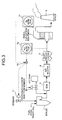
- [Fig. 3] Fig. 3 is a schematic of a general structure of a system for removing mercury from flue gas according to a second embodiment of the present invention;
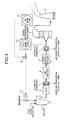
- [Fig. 4] Fig. 4 is a schematic of a general structure of a system for removing mercury from flue gas according to a third embodiment of the present invention; and
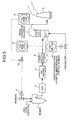
- [Fig. 5] Fig. 5 is a schematic of a general structure of a system for removing mercury from flue gas according to a fourth embodiment of the present invention.
-
- 1
- Boiler
- 2
- Desulfurization equipment
- 3
- Selective catalytic reducer
- 4
- Air heater
- 5
- Dust precipitator
- 6
- Stack
- 11
- Biomass feeding unit
- 12
- Hydrogen chloride monitor
- 13
- Mercury monitor
- 14
- Determining device (feed-amount instruction member)
- 20
- Hydrogen-chloride injection member
- 31, 32
- Mercury-oxidation catalyst tank
- 41
- Oxidation-reduction-potential measurement-control member
- Exemplary embodiments of a system and a method of moving mercury from flue gas according to the present invention are explained below in detail with reference to the accompanying drawings. The present invention is not limited to the embodiments explained below.
- Fig. 1 is a schematic of a general structure of a system for removing mercury from flue gas according to a first embodiment of the present invention.
- The system for removing mercury according to the present invention realizes a function of removing mercury when the system is installed in an existing flue-gas treatment facility including a wet desulfurization equipment. The existing flue-gas treatment facility having a minimal structure includes a
boiler 1 and adesulfurization equipment 2 for removing sulfur component from flue gas emitted from theboiler 1. Generally, in addition to the above structure, a selective catalytic reducer (SCR) 3, anair heater 4, and adust precipitator 5 are sequentially installed, from an upstream side, between theboiler 1 and thedesulfurization equipment 2. The flue gas from thedesulfurization equipment 2 is emitted from astack 6. - The system for removing mercury from flue gas according to the first embodiment includes a
biomass feeding unit 11 that feeds biomass to theboiler 1, a hydrogen chloride monitor 12 that monitors a hydrogen chloride content in the flue gas fed to thedesulfurization equipment 2, namely, the flue gas emitted from thedust precipitator 5, amercury monitor 13 that monitors a mercury content in treated flue gas emitted from thedesulfurization equipment 2, and a determining device (feed-amount instruction member) 14 that instructs a proper feed-amount of the biomass to thebiomass feeding unit 11 based on each measurement of thehydrogen chloride monitor 12 and themercury monitor 13. - The system of removing mercury from flue gas, according to the first embodiment, includes the
biomass feeding unit 11 that feeds the biomass containing chlorine to theboiler 1, the hydrogen chloride monitor 12 that monitors the hydrogen chloride content in the flue gas fed to thedesulfurization equipment 2, the mercury monitor 13 that monitors the mercury content in the treated flue gas emitted from thedesulfurization equipment 2. The determiningdevice 14 determines a feed amount of the biomass, in proportion to an amount of chlorine enabling to remove the mercury by the chlorine in thedesulfurization equipment 2, based on each measurement value of thehydrogen chloride monitor 12 and themercury monitor 13. According the determination, the determiningdevice 14 sends a control signal to thebiomass feeding unit 11 to control the amount of the biomass to be fed. - According to the first embodiment, hydrogen chloride concentration and mercury concentration in the flue gas can be monitored and the amount of the biomass to be fed can be controlled. If the hydrogen chloride concentration in the flue gas decreases and/or the mercury concentration in the flue gas at an inlet of the
stack 6 increases, a relative amount of the biomass in mixture of fuel is to be increased so that the hydrogen chloride of fuel is to be increased so that the hydrogen chloride concentration of the flue gas increases to induce an oxidization of the mercury in the flue gas. As a result, mercury removal efficiency in thedesulfurization equipment 2 can be improved. - The determining
device 14 primarily determines whether the mercury monitor 13 detects even a small amount of mercury in the flue gas and sends the control signal to thebiomass feeding unit 11 for increasing the feed amount of the biomass. When the mercury monitor 13 does not detect mercury in the flue gas, if the chlorine concentration in the flue gas is less than that necessary for removing the mercury in thedesulfurization equipment 2, the determiningdevice 14 sends the control signal to thebiomass feeding unit 11 for increasing the feed amount of the biomass. - The necessary amount of chlorine for removing the mercury in the
desulfurization equipment 2 is explained below.
To remove the mercury in the desulfurization equipment, the mercury needs to be water-soluble divalent mercury. It is widely known that, when the hydrogen chloride concentration in the flue gas increases, a ratio of the divalent mercury in the flue gas increase, resulting in making the removal of the mercury in thedesulfurization equipment 2 easier. Fig. 2 is a graph of a relationship between the hydrogen chloride concentration in the flue gas and mercury oxidation ratio with a predetermined amount of desulfurization catalyst in a downstream side of thedesulfurization equipment 2, which is expressed by
- To feed the necessary amount of the chlorine for removing the mercury in the
desulfurization equipment 2 only by mixing the biomass in the fuel, for example, by referring to the relationship between the hydrogen chloride concentration and the mercury oxidation ratio shown in Fig. 2, if a target mercury oxidation ratio is determined as 90%, the biomass having chlorine content of more than 0.1 wt% on dry-ash free basis is needed (the relative amount of the biomass in the mixture of the fuel is 5 cal% assuming a heating value of carbide of sewage sludge). - The structure explained in the first embodiment is a basic structure of the system for removing mercury from flue gas according to the present invention. According to a second embodiment of the present invention shown in Fig. 3, a hydrogen-
chloride injection member 20 is installed between theboiler 1 and theSCR 3 for injecting hydrogen chloride into flue gas. - The system for removing mercury from flue gas according to the second embodiment includes the hydrogen-
chloride injection member 20 for injecting the hydrogen chloride into the flue gas emitted from theboiler 1. If an amount of the chlorine fed from the biomass is deficient, the hydrogen chloride is injected into the flue gas by the hydrogen-chloride injection member 20 for making up the deficiency of the chlorine. - According to the second embodiment, the hydrogen chloride concentration and the mercury concentration in the flue gas can be monitored, the determining
device 14 determines whether an amount of the chlorine to be added by the biomass is deficient, and the hydrogen chloride gas is injected into the flue gas for making up the deficiency of the chlorine. In other words, when mercury is not sufficiently oxidized by the biomass and/or chloride induced from other fuel, the hydrogen-chloride injection member 20 is installed to make up the deficiency of the chlorine. By increasing the hydrogen chloride concentration in the flue gas, mercury oxidation can be further induced and the mercury removal efficiency in thedesulfurization equipment 2 can be improved. - Fig. 4 is a schematic for explaining a third embodiment according to the present invention. According to the third embodiment, in addition to the configuration of the first embodiment, a mercury-oxidation catalyst tank is installed in at least one of a downstream side of the
SCR 3 equipped in a downstream side of an outlet of theboiler 1 and a downstream side of thedust precipitator 5. A mercury-oxidation catalyst tank 31 can be installed in the downstream side of theSCR 3, and alternately, the mercury-oxidation catalyst tank 31 can be installed in the downstream side of thedust precipitator 5, each of which makes no significant differences in terms of effectiveness. In terms of effectiveness, it is preferable to install the two mercury-oxidation catalyst tanks. However, one mercury-oxidation catalyst tank is effective enough. - The system for removing mercury from flue gas according to the third embodiment includes at least one of the mercury-oxidation catalyst tank 31 (32) on a path of the flue gas, between the outlet of the
boiler 1 and a position where the hydrogen-chloride monitor 12 is installed, to induce the oxidation of the mercury in the flue gas fed to thedesulfurization equipment 2. - According to the system for removing mercury from flue gas of the third embodiment, the mercury-
oxidation catalyst tank 31 and/or a mercury-oxidation catalyst tank 32 are installed to further induce the oxidation of the mercury in the flue gas. As for a catalyst, at least one of TiO2, SiO2, ZrO2, Al2O3, and zeolite is used for a carrier and the carrier supporting at least one of Pt, Ru, Rh, Pd, Ir, V, W, Mo, Ni, Co, Fe, Cr, Cu, and Mn is used for the catalyst. - Fig. 5 is a schematic for explaining a fourth embodiment according to the present invention. According to the fourth embodiment, in addition to the configuration of the first embodiment, an oxidation-reduction-potential measurement-
control member 41 is further installed to measure an oxidation-reduction-potential value of absorbing solution collected in a bottom portion of thedesulfurization equipment 2 and to control a feed amount of an oxidation agent to be fed to the bottom portion of thedesulfurization equipment 2 based on the measured oxidation-reduction-potential value. - According to the system for removing mercury from flue gas of the fourth embodiment, the oxidation-reduction-potential measurement-
control member 41 is further installed to measure the oxidation-reduction-potential value of the absorbing solution collected in the bottom portion of thedesulfurization equipment 2 and to control the feed amount of the oxidation agent to be fed to the bottom portion of thedesulfurization equipment 2 based on the measured oxidation-reduction-potential value. Owing to the oxidation-reduction-potential measurement-control member 41, re-emission of the mercury trapped in the absorbing solution collected in the bottom portion of thedesulfurization equipment 2 can be prevented. - According to the fourth embodiment, the oxidation-reduction-potential measurement-
control member 41 is further installed to thedesulfurization equipment 2 to control the feed amount of oxidation air or the oxidation agent. The feed amount of the oxidation air or the oxidation agent can be controlled and the absorbing solution can be oxidative atmosphere. As a result, the re-emission of the mercury from the absorbing solution can be prevented. - The oxidation-reduction-potential value of the absorbing solution in the
desulfurization equipment 2 needs to range between 150 mV and 600 mV to prevent the re-emission of the mercury from the absorbing solution. When the oxidation-reduction-potential value is in the above range, the mercury trapped as HgCl2 in the absorbing solution becomes stable, so that the re-emission of the mercury to air can be prevented. A technology for preventing the re-emission of the mercury by using the oxidation-reduction-potential value is disclosed inJapanese Patent Application Laid-Open No. 2004-313833 - The mercury removal efficiency was measured in the system according to the third embodiment shown in Fig. 4, under a condition that only the mercury-
oxidation catalyst tank 32 was installed in the downstream side of thedust precipitator 5. For evaluations, gas sampling was conducted in three positions: between thedust precipitator 5 and the mercury-oxidation catalyst tank 32 (S1), between the mercury-oxidation catalyst tank 32 and the desulfurization equipment 2 (S2), and right after an outlet of the desulfurization equipment 2 (S3). - Carbide of sewage sludge was used as a biomass to be dual-fueled. The chlorine concentration of the carbide of the sewage sludge was 0.2 wt% on dry-ash free basis. A relative amount of the biomass to be dual-fueled was fixed at 5 cal%.
- As a mercury oxidation catalyst, a catalyst mainly containing V2O5/TiO2-SiO2 was used. Catalyst temperature was set at 350°C and catalyst SV was set to 6000h-1.
- Actual measurement was conducted under conditions, of which the biomass was dual-fueled, and of which the biomass was not dual-fueled, as for gas composition of the flue gas obtained at the outlet of the
boiler 1. A result obtained from the measurement is shown below in a table 1. - [Table 1]
Table 1: Gas composition (Example: at outlet of boiler 1) Item Coal Single-fuel Coal/Biomass Dual-fuel Pressure Normal Normal H2O % (wet) 8 8 CO2 % (dry) 15 15 O2 % (dry) 4 4 N2 % (dry) Balance Balance HCl ppm (dry) 5 22 SO2 ppm (dry) 210 257 Dust g/m3N (dry) 13 20 Hg µg/m3N (dry) 30 30 - According to the present invention, the sampling gases obtained at each sampling position of S1, S2, and S3 was analyzed under the conditions, of which the biomass was dual-fueled, and of which the biomass was not dual-fueled. A result of the analysis is shown below in a table 2.
- [Table 2]
Table 2: Gas sampling result Sampling point S1 S2 S3 Position Upstream of catalyst Downstream of Downstream of catalyst Downstream of desulfurization equipment Item Single-fuel Dual-fuel Single-fuel Dual-fuel Single-fuel Dual- fuel HCl concentration 5 17 5 17 <1 <1 Total Hg concentration 30 30 30 30 9.3 4.8 HgCl2 concentration 2.7 3.5 21.8 26.6 0.7 0.9 Hg oxidation ratio - - 73 89 - - Hg removal ratio - - - - 69 84 *1 Hg oxidation ratio=(HgCl2 concentration (µg/m3N) at sampling position S2/total Hg concentration (µg/m3N) at sampling position S2)×100
*2 Hg removal ratio=[((total Hg concentration at sampling position S2)-(total Hg concentration at sampling position S3))/total Hg concentration at sampling position S2]×100 - As assured in the table 1, mercury content in the flue gas from the
boiler 1 was the same as 30 µg/m3N under the both conditions, of which the biomass was dual-fueled, and of which the biomass was not dual-fueled. As is clear from the table 2, mercury content in the flue gas from thedesulfurization equipment 2 was 9.3 µg/m3N when the biomass was not dual-fueled. Alternately, mercury content in the flue gas from thedesulfurization equipment 2 was decreased to 4.8 µg/m3N when the biomass was dual-fueled according to the present invention. The residual amount of 4.8 µg/m3N can be further decreased by installing the hydrogen-chloride injection member 20 shown in Fig. 3 according to the second embodiment. - As described above, according to the method and system for removing mercury from flue gas of the present invention, mercury can be effectively removed from flue gas without degrading a combustion efficiency of a boiler and without increasing combustion residue. Further, costs for a removal operation can be reduced.
Claims (8)
- A mercury removing system for removing mercury from flue gas treated in a flue-gas treatment system including a boiler and a desulfurization equipment that removes sulfur component from flue gas emitted from the boiler, the mercury removing system comprising:a biomass feeding unit that feeds biomass to the boiler;a hydrogen-chlorine monitoring unit that measures hydrogen-chloride content in the flue gas fed to the desulfurization equipment;a mercury monitoring unit that measures mercury content in treated flue gas emitted from the desulfurization equipment; anda feed-amount instruction unit that instructs proper feed amount of the biomass to the biomass feeding unit based on measurement values obtained by the hydrogen-chlorine monitoring unit and the mercury monitoring unit.
- The mercury removing system according to claim 1, further comprising:a hydrogen-chloride injection unit that injects hydrogen chloride to the flue gas emitted from the boiler.
- The mercury removing system according to claim 1 or 2, further comprising:at least one mercury-oxidation catalyst tank installed on a flue-gas path between an outlet of the boiler and a position where the hydrogen-chlorine monitoring unit is installed.
- The mercury removing system according to any one of claims 1 to 3, further comprising:an oxidation-reduction-potential control unit that measures an oxidation-reduction-potential of absorbing solution collected at a bottom portion of the desulfurization equipment, and controls feed amount of an oxidation agent to be fed to the bottom portion of the desulfurization equipment based on the measured oxidation-reduction-potential.
- A method of removing mercury from flue gas treated in a flue-gas treatment system that includes a boiler and a desulfurization equipment for removing sulfur from flue gas emitted from the boiler, the method comprising:feeding biomass to the boiler;measuring hydrogen-chloride content in the flue gas fed to the desulfurization equipment;measuring mercury content in treated flue gas emitted from the desulfurization equipment; andcontrolling proper feed amount of the biomass, in proportion to chlorine amount enabling to remove mercury in the desulfurization equipment, based on measurement values obtained by measuring the hydrogen-chlorine content and measuring the mercury content.
- The method according to claim 5, further comprising:injecting hydrogen chloride to the flue gas emitted from the boiler, whereinthe injecting includes injecting, when chlorine amount fed by the biomass is deficient, hydrogen chloride by an amount of deficiency to the flue gas by using the hydrogen-chloride injection unit.
- The method according to claim 5 or 6, further comprising:promoting oxidation of mercury in the flue gas fed to the desulfurization equipment by installing at least one mercury-oxidation catalyst tank on a flue-gas path between an outlet of the boiler and a position where the hydrogen-chlorine monitoring unit is installed.
- The method according to any one of claims 5 to 7, further comprising:preventing re-emission of mercury trapped in the absorbing solution collected in the bottom portion of the desulfurization equipment by installing an oxidation-reduction-potential control unit that measures an oxidation-reduction-potential of absorbing solution collected at a bottom portion of the desulfurization equipment, and controlling feed amount of an oxidation agent to be fed to the bottom portion of the desulfurization equipment based on the measured oxidation-reduction-potential.
Priority Applications (1)
| Application Number | Priority Date | Filing Date | Title |
|---|---|---|---|
| PL06714456T PL1854529T3 (en) | 2005-02-28 | 2006-02-23 | System and method for removing mercury in exhaust gas |
Applications Claiming Priority (3)
| Application Number | Priority Date | Filing Date | Title |
|---|---|---|---|
| JP2005054199 | 2005-02-28 | ||
| JP2005139696A JP2006263700A (en) | 2005-02-28 | 2005-05-12 | Method and system for removing mercury in exhaust gas |
| PCT/JP2006/303316 WO2006093026A1 (en) | 2005-02-28 | 2006-02-23 | System and method for removing mercury in exhaust gas |
Publications (3)
| Publication Number | Publication Date |
|---|---|
| EP1854529A1 true EP1854529A1 (en) | 2007-11-14 |
| EP1854529A4 EP1854529A4 (en) | 2008-04-23 |
| EP1854529B1 EP1854529B1 (en) | 2013-11-06 |
Family
ID=36941060
Family Applications (1)
| Application Number | Title | Priority Date | Filing Date |
|---|---|---|---|
| EP06714456.8A Expired - Lifetime EP1854529B1 (en) | 2005-02-28 | 2006-02-23 | System and method for removing mercury in exhaust gas |
Country Status (8)
| Country | Link |
|---|---|
| US (1) | US7662352B2 (en) |
| EP (1) | EP1854529B1 (en) |
| JP (1) | JP2006263700A (en) |
| CA (1) | CA2577826C (en) |
| DK (1) | DK1854529T3 (en) |
| ES (1) | ES2443652T3 (en) |
| PL (1) | PL1854529T3 (en) |
| WO (1) | WO2006093026A1 (en) |
Cited By (3)
| Publication number | Priority date | Publication date | Assignee | Title |
|---|---|---|---|---|
| US7704472B2 (en) | 2008-04-25 | 2010-04-27 | Mitsubishi Heavy Industries, Ltd. | Air pollutant control system and method for removing mercury in flue gas |
| EP1972369A3 (en) * | 2007-03-23 | 2011-02-02 | Alstom Technology Ltd | Method of mercury removal in a wet flue gas desulfurization system |
| US8961170B2 (en) | 2007-05-14 | 2015-02-24 | Babcock-Hitachi K.K. | Dust coal boiler, dust coal combustion method, dust coal fuel thermal power generation system, and waste gas purification system for dust coal boiler |
Families Citing this family (12)
| Publication number | Priority date | Publication date | Assignee | Title |
|---|---|---|---|---|
| JP4838579B2 (en) | 2005-12-21 | 2011-12-14 | 三菱重工業株式会社 | Mercury removal system and mercury removal method |
| JP5060776B2 (en) * | 2006-12-04 | 2012-10-31 | 日立造船株式会社 | Method and apparatus for recovering mercury from exhaust gas |
| JP4388542B2 (en) | 2006-12-07 | 2009-12-24 | 三菱重工業株式会社 | Mercury removal method and mercury removal system |
| JP5160107B2 (en) * | 2007-03-07 | 2013-03-13 | 千代田化工建設株式会社 | Flue gas treatment method |
| ES2435318T3 (en) * | 2007-03-07 | 2013-12-18 | Chiyoda Corporation | Exhaust gas treatment method using gaseous iodine |
| JP5299601B2 (en) * | 2007-08-15 | 2013-09-25 | 株式会社Ihi | Exhaust gas treatment method and exhaust gas treatment apparatus |
| JP5319934B2 (en) * | 2008-02-28 | 2013-10-16 | 三菱重工業株式会社 | Exhaust gas treatment method and apparatus |
| JP5556068B2 (en) * | 2009-07-03 | 2014-07-23 | 株式会社Ihi | Fluid diffusion equipment for exhaust gas treatment equipment |
| JP5564846B2 (en) * | 2009-07-23 | 2014-08-06 | 株式会社Ihi | Exhaust gas treatment method and exhaust gas treatment equipment |
| JP2012035216A (en) * | 2010-08-09 | 2012-02-23 | Babcock Hitachi Kk | Catalyst for treating exhaust gas, method for producing the same, and method for treating nitrogen oxide in exhaust gas |
| CN102818248B (en) * | 2012-07-20 | 2014-03-26 | 广东电网公司电力科学研究院 | High-chlorine biomass and coal co-utilizing system with low-chlorine-corrosion and low-mercury discharge and method |
| US20170326498A1 (en) * | 2016-05-11 | 2017-11-16 | General Electric Company | Sulfite Preconditioning Systems And Methods To Reduce Mercury Concentrations In Waste Water |
Family Cites Families (8)
| Publication number | Priority date | Publication date | Assignee | Title |
|---|---|---|---|---|
| DE3314969C1 (en) * | 1983-04-26 | 1984-10-04 | Müller, Dietrich, Dr., 2000 Hamburg | Process for removing or isolating pollutants from exhaust gases |
| JPS61222525A (en) | 1985-03-28 | 1986-10-03 | Tokyo Met Gov Kankyo Seibi Koushiya | Purification of exhaust gas containing mercury |
| JP3935547B2 (en) | 1997-02-19 | 2007-06-27 | 三菱重工業株式会社 | Exhaust gas treatment method and exhaust gas treatment apparatus |
| JP3698916B2 (en) | 1999-05-19 | 2005-09-21 | バブコック日立株式会社 | Method and apparatus for removing mercury from coal flue gas |
| JP2002177741A (en) | 2000-12-18 | 2002-06-25 | Miura Co Ltd | Method of controlling denitration apparatus in boiler |
| JP2002349821A (en) * | 2001-05-30 | 2002-12-04 | Hitachi Ltd | Solid fuel combustion apparatus and combustion method and pulverized coal boiler modification method |
| DE10233173B4 (en) * | 2002-07-22 | 2006-03-23 | Bayer Industry Services Gmbh & Co. Ohg | Method for separating mercury from flue gases |
| JP4395315B2 (en) * | 2003-04-11 | 2010-01-06 | 三菱重工業株式会社 | Method and system for removing mercury from exhaust gas |
-
2005
- 2005-05-12 JP JP2005139696A patent/JP2006263700A/en active Pending
-
2006
- 2006-02-23 PL PL06714456T patent/PL1854529T3/en unknown
- 2006-02-23 EP EP06714456.8A patent/EP1854529B1/en not_active Expired - Lifetime
- 2006-02-23 US US11/574,134 patent/US7662352B2/en not_active Expired - Lifetime
- 2006-02-23 ES ES06714456.8T patent/ES2443652T3/en not_active Expired - Lifetime
- 2006-02-23 DK DK06714456.8T patent/DK1854529T3/en active
- 2006-02-23 CA CA2577826A patent/CA2577826C/en not_active Expired - Fee Related
- 2006-02-23 WO PCT/JP2006/303316 patent/WO2006093026A1/en not_active Ceased
Non-Patent Citations (2)
| Title |
|---|
| No further relevant documents disclosed * |
| See also references of WO2006093026A1 * |
Cited By (5)
| Publication number | Priority date | Publication date | Assignee | Title |
|---|---|---|---|---|
| EP1972369A3 (en) * | 2007-03-23 | 2011-02-02 | Alstom Technology Ltd | Method of mercury removal in a wet flue gas desulfurization system |
| US8961170B2 (en) | 2007-05-14 | 2015-02-24 | Babcock-Hitachi K.K. | Dust coal boiler, dust coal combustion method, dust coal fuel thermal power generation system, and waste gas purification system for dust coal boiler |
| US7704472B2 (en) | 2008-04-25 | 2010-04-27 | Mitsubishi Heavy Industries, Ltd. | Air pollutant control system and method for removing mercury in flue gas |
| EP2269714A4 (en) * | 2008-04-25 | 2011-11-23 | Mitsubishi Heavy Ind Ltd | System for treating discharge gas and method of removing mercury from discharge gas |
| CN102015070B (en) * | 2008-04-25 | 2013-09-04 | 三菱重工业株式会社 | System for treating discharge gas and method of removing mercury from discharge gas |
Also Published As
| Publication number | Publication date |
|---|---|
| EP1854529B1 (en) | 2013-11-06 |
| CA2577826C (en) | 2010-08-03 |
| DK1854529T3 (en) | 2014-01-13 |
| JP2006263700A (en) | 2006-10-05 |
| ES2443652T3 (en) | 2014-02-20 |
| US20090004085A1 (en) | 2009-01-01 |
| PL1854529T3 (en) | 2014-04-30 |
| EP1854529A4 (en) | 2008-04-23 |
| WO2006093026A1 (en) | 2006-09-08 |
| US7662352B2 (en) | 2010-02-16 |
| CA2577826A1 (en) | 2006-09-08 |
| HK1111374A1 (en) | 2008-08-08 |
Similar Documents
| Publication | Publication Date | Title |
|---|---|---|
| EP1854529B1 (en) | System and method for removing mercury in exhaust gas | |
| US8703080B2 (en) | Method for removing mercury in exhaust gas and system therefor | |
| US8071060B2 (en) | Flue gas control system of coal combustion boiler and operating method thereof | |
| EP2328675B1 (en) | METHOD AND EXHAUST GAS SYSTEM FOR SCRUBBING EXHAUST GASES CONTAINING SOx, IN PARTICULAR ONBOARD INTERNAL COMBUSTION ENGINES OF SHIPS | |
| US20030235525A1 (en) | Method for the treating in exhaust gas and exhaust gas treating system | |
| US6375909B1 (en) | Method for the removal of mercury and nitrogen oxides from combustion flue gas | |
| KR100815175B1 (en) | Removal of Nitrogen Oxides and Dioxins from Combustion Exhaust Gas Using Powdered Impregnated Activated Carbon | |
| CN102202767A (en) | Method for removing mercury from combustion gas, and combustion gas cleaner | |
| RU2501596C2 (en) | Method and plant for purification of combustion gases containing nitrogen oxides | |
| WO1998048924A1 (en) | Method of treating exhaust gas | |
| JP2009208078A (en) | Method for treating mercury in tail gas, and treatment system for tail gas | |
| EP1029580B1 (en) | Method for removing nitrogen oxides in exhaust gas | |
| HK1111374B (en) | System and method for removing mercury in exhaust gas | |
| CN103047662A (en) | Catalytic combustion treatment device and treatment method for organic waste gases | |
| DE19814386C2 (en) | Method and device for the catalytic removal of nitrogen oxides in the exhaust gas of an incineration plant | |
| KR100767161B1 (en) | Nitrogen oxide and dioxin removal apparatus from combustion exhaust gas using powdered impregnated activated carbon | |
| EP3036480B1 (en) | Arrangement and method for flue gas stream bypass during selective catalytic reduction | |
| KR20210077018A (en) | Method for treating exhaust gas | |
| JP3779889B2 (en) | Catalyst regeneration method | |
| JP6400379B2 (en) | Denitration method for combustion exhaust gas | |
| WO2003008072A1 (en) | Method for treating mercury in exhaust gas and exhaust gas treating system | |
| JP2015223583A (en) | Degradation detection and recovery method of exhaust gas oxidation catalyst in heat engine, heat engine exhaust emission control device for implementing method, and mechanical system with exhaust emission control device | |
| KR20220086927A (en) | Dust collector for the simultaneous treatment of dust and volatile organic compounds from exhaust gas | |
| CN222567358U (en) | Treatment system for ammonia-containing tail gas | |
| EP0698411A1 (en) | Method for removing nitrous oxide |
Legal Events
| Date | Code | Title | Description |
|---|---|---|---|
| PUAI | Public reference made under article 153(3) epc to a published international application that has entered the european phase |
Free format text: ORIGINAL CODE: 0009012 |
|
| 17P | Request for examination filed |
Effective date: 20070222 |
|
| AK | Designated contracting states |
Kind code of ref document: A1 Designated state(s): AT BE BG CH CY CZ DE DK EE ES FI FR GB GR HU IE IS IT LI LT LU LV MC NL PL PT RO SE SI SK TR |
|
| RIN1 | Information on inventor provided before grant (corrected) |
Inventor name: NAKAYAMA, YOSHIO MITSUBISHI HEAVY INDUSTRIES Inventor name: SUGITA, SATORU MITSUBISHI HEAVY INDUSTRIES Inventor name: OKINO, SUSUMU MITSUBISHI HEAVY INDUSTRIES Inventor name: TAKEUCHI, YASUHIRO MITSUBISHI HEAVY INDUSTRIES Inventor name: HONJO, SHINTARO MITSUBISHI HEAVY INDUSTRIES, LTD. |
|
| A4 | Supplementary search report drawn up and despatched |
Effective date: 20080327 |
|
| DAX | Request for extension of the european patent (deleted) | ||
| REG | Reference to a national code |
Ref country code: HK Ref legal event code: DE Ref document number: 1111374 Country of ref document: HK |
|
| REG | Reference to a national code |
Ref country code: DE Ref legal event code: R079 Ref document number: 602006039110 Country of ref document: DE Free format text: PREVIOUS MAIN CLASS: B01D0053640000 Ipc: B01D0053340000 |
|
| RIC1 | Information provided on ipc code assigned before grant |
Ipc: B01D 53/75 20060101ALI20130418BHEP Ipc: B01D 53/50 20060101ALI20130418BHEP Ipc: B01D 53/34 20060101AFI20130418BHEP Ipc: B01D 53/79 20060101ALI20130418BHEP Ipc: B01D 53/64 20060101ALI20130418BHEP Ipc: B01D 53/86 20060101ALI20130418BHEP |
|
| GRAP | Despatch of communication of intention to grant a patent |
Free format text: ORIGINAL CODE: EPIDOSNIGR1 |
|
| INTG | Intention to grant announced |
Effective date: 20130529 |
|
| RIN1 | Information on inventor provided before grant (corrected) |
Inventor name: NAKAYAMA, YOSHIO MITSUBISHI HEAVY INDUSTRIES Inventor name: OKINO, SUSUMU MITSUBISHI HEAVY INDUSTRIES Inventor name: SUGITA, SATORU MITSUBISHI HEAVY INDUSTRIES Inventor name: HONJO, SHINTARO MITSUBISHI HEAVY INDUSTRIES, LTD. Inventor name: TAKEUCHI, YASUHIRO MITSUBISHI HEAVY INDUSTRIES |
|
| GRAS | Grant fee paid |
Free format text: ORIGINAL CODE: EPIDOSNIGR3 |
|
| GRAA | (expected) grant |
Free format text: ORIGINAL CODE: 0009210 |
|
| AK | Designated contracting states |
Kind code of ref document: B1 Designated state(s): AT BE BG CH CY CZ DE DK EE ES FI FR GB GR HU IE IS IT LI LT LU LV MC NL PL PT RO SE SI SK TR |
|
| REG | Reference to a national code |
Ref country code: GB Ref legal event code: FG4D |
|
| REG | Reference to a national code |
Ref country code: CH Ref legal event code: EP |
|
| REG | Reference to a national code |
Ref country code: AT Ref legal event code: REF Ref document number: 639046 Country of ref document: AT Kind code of ref document: T Effective date: 20131215 |
|
| REG | Reference to a national code |
Ref country code: IE Ref legal event code: FG4D |
|
| REG | Reference to a national code |
Ref country code: DE Ref legal event code: R096 Ref document number: 602006039110 Country of ref document: DE Effective date: 20140102 |
|
| REG | Reference to a national code |
Ref country code: DK Ref legal event code: T3 Effective date: 20140109 |
|
| REG | Reference to a national code |
Ref country code: ES Ref legal event code: FG2A Ref document number: 2443652 Country of ref document: ES Kind code of ref document: T3 Effective date: 20140220 |
|
| REG | Reference to a national code |
Ref country code: NL Ref legal event code: VDEP Effective date: 20131106 |
|
| REG | Reference to a national code |
Ref country code: AT Ref legal event code: MK05 Ref document number: 639046 Country of ref document: AT Kind code of ref document: T Effective date: 20131106 |
|
| REG | Reference to a national code |
Ref country code: HK Ref legal event code: GR Ref document number: 1111374 Country of ref document: HK |
|
| REG | Reference to a national code |
Ref country code: LT Ref legal event code: MG4D |
|
| PG25 | Lapsed in a contracting state [announced via postgrant information from national office to epo] |
Ref country code: IS Free format text: LAPSE BECAUSE OF FAILURE TO SUBMIT A TRANSLATION OF THE DESCRIPTION OR TO PAY THE FEE WITHIN THE PRESCRIBED TIME-LIMIT Effective date: 20140306 Ref country code: FI Free format text: LAPSE BECAUSE OF FAILURE TO SUBMIT A TRANSLATION OF THE DESCRIPTION OR TO PAY THE FEE WITHIN THE PRESCRIBED TIME-LIMIT Effective date: 20131106 Ref country code: LT Free format text: LAPSE BECAUSE OF FAILURE TO SUBMIT A TRANSLATION OF THE DESCRIPTION OR TO PAY THE FEE WITHIN THE PRESCRIBED TIME-LIMIT Effective date: 20131106 Ref country code: SE Free format text: LAPSE BECAUSE OF FAILURE TO SUBMIT A TRANSLATION OF THE DESCRIPTION OR TO PAY THE FEE WITHIN THE PRESCRIBED TIME-LIMIT Effective date: 20131106 Ref country code: NL Free format text: LAPSE BECAUSE OF FAILURE TO SUBMIT A TRANSLATION OF THE DESCRIPTION OR TO PAY THE FEE WITHIN THE PRESCRIBED TIME-LIMIT Effective date: 20131106 |
|
| REG | Reference to a national code |
Ref country code: PL Ref legal event code: T3 |
|
| PG25 | Lapsed in a contracting state [announced via postgrant information from national office to epo] |
Ref country code: BE Free format text: LAPSE BECAUSE OF FAILURE TO SUBMIT A TRANSLATION OF THE DESCRIPTION OR TO PAY THE FEE WITHIN THE PRESCRIBED TIME-LIMIT Effective date: 20131106 Ref country code: AT Free format text: LAPSE BECAUSE OF FAILURE TO SUBMIT A TRANSLATION OF THE DESCRIPTION OR TO PAY THE FEE WITHIN THE PRESCRIBED TIME-LIMIT Effective date: 20131106 Ref country code: LV Free format text: LAPSE BECAUSE OF FAILURE TO SUBMIT A TRANSLATION OF THE DESCRIPTION OR TO PAY THE FEE WITHIN THE PRESCRIBED TIME-LIMIT Effective date: 20131106 |
|
| PG25 | Lapsed in a contracting state [announced via postgrant information from national office to epo] |
Ref country code: PT Free format text: LAPSE BECAUSE OF FAILURE TO SUBMIT A TRANSLATION OF THE DESCRIPTION OR TO PAY THE FEE WITHIN THE PRESCRIBED TIME-LIMIT Effective date: 20140306 |
|
| PG25 | Lapsed in a contracting state [announced via postgrant information from national office to epo] |
Ref country code: EE Free format text: LAPSE BECAUSE OF FAILURE TO SUBMIT A TRANSLATION OF THE DESCRIPTION OR TO PAY THE FEE WITHIN THE PRESCRIBED TIME-LIMIT Effective date: 20131106 |
|
| REG | Reference to a national code |
Ref country code: DE Ref legal event code: R097 Ref document number: 602006039110 Country of ref document: DE |
|
| PG25 | Lapsed in a contracting state [announced via postgrant information from national office to epo] |
Ref country code: CZ Free format text: LAPSE BECAUSE OF FAILURE TO SUBMIT A TRANSLATION OF THE DESCRIPTION OR TO PAY THE FEE WITHIN THE PRESCRIBED TIME-LIMIT Effective date: 20131106 Ref country code: RO Free format text: LAPSE BECAUSE OF FAILURE TO SUBMIT A TRANSLATION OF THE DESCRIPTION OR TO PAY THE FEE WITHIN THE PRESCRIBED TIME-LIMIT Effective date: 20131106 Ref country code: SK Free format text: LAPSE BECAUSE OF FAILURE TO SUBMIT A TRANSLATION OF THE DESCRIPTION OR TO PAY THE FEE WITHIN THE PRESCRIBED TIME-LIMIT Effective date: 20131106 |
|
| PLBE | No opposition filed within time limit |
Free format text: ORIGINAL CODE: 0009261 |
|
| STAA | Information on the status of an ep patent application or granted ep patent |
Free format text: STATUS: NO OPPOSITION FILED WITHIN TIME LIMIT |
|
| PG25 | Lapsed in a contracting state [announced via postgrant information from national office to epo] |
Ref country code: MC Free format text: LAPSE BECAUSE OF FAILURE TO SUBMIT A TRANSLATION OF THE DESCRIPTION OR TO PAY THE FEE WITHIN THE PRESCRIBED TIME-LIMIT Effective date: 20131106 Ref country code: LU Free format text: LAPSE BECAUSE OF FAILURE TO SUBMIT A TRANSLATION OF THE DESCRIPTION OR TO PAY THE FEE WITHIN THE PRESCRIBED TIME-LIMIT Effective date: 20140223 |
|
| REG | Reference to a national code |
Ref country code: CH Ref legal event code: PL |
|
| 26N | No opposition filed |
Effective date: 20140807 |
|
| PG25 | Lapsed in a contracting state [announced via postgrant information from national office to epo] |
Ref country code: CH Free format text: LAPSE BECAUSE OF NON-PAYMENT OF DUE FEES Effective date: 20140228 Ref country code: LI Free format text: LAPSE BECAUSE OF NON-PAYMENT OF DUE FEES Effective date: 20140228 |
|
| REG | Reference to a national code |
Ref country code: DE Ref legal event code: R097 Ref document number: 602006039110 Country of ref document: DE Effective date: 20140807 |
|
| REG | Reference to a national code |
Ref country code: FR Ref legal event code: ST Effective date: 20141031 |
|
| REG | Reference to a national code |
Ref country code: IE Ref legal event code: MM4A |
|
| PG25 | Lapsed in a contracting state [announced via postgrant information from national office to epo] |
Ref country code: FR Free format text: LAPSE BECAUSE OF NON-PAYMENT OF DUE FEES Effective date: 20140228 Ref country code: IE Free format text: LAPSE BECAUSE OF NON-PAYMENT OF DUE FEES Effective date: 20140223 |
|
| PG25 | Lapsed in a contracting state [announced via postgrant information from national office to epo] |
Ref country code: SI Free format text: LAPSE BECAUSE OF FAILURE TO SUBMIT A TRANSLATION OF THE DESCRIPTION OR TO PAY THE FEE WITHIN THE PRESCRIBED TIME-LIMIT Effective date: 20131106 |
|
| PG25 | Lapsed in a contracting state [announced via postgrant information from national office to epo] |
Ref country code: BG Free format text: LAPSE BECAUSE OF FAILURE TO SUBMIT A TRANSLATION OF THE DESCRIPTION OR TO PAY THE FEE WITHIN THE PRESCRIBED TIME-LIMIT Effective date: 20131106 |
|
| PG25 | Lapsed in a contracting state [announced via postgrant information from national office to epo] |
Ref country code: CY Free format text: LAPSE BECAUSE OF FAILURE TO SUBMIT A TRANSLATION OF THE DESCRIPTION OR TO PAY THE FEE WITHIN THE PRESCRIBED TIME-LIMIT Effective date: 20131106 Ref country code: GR Free format text: LAPSE BECAUSE OF FAILURE TO SUBMIT A TRANSLATION OF THE DESCRIPTION OR TO PAY THE FEE WITHIN THE PRESCRIBED TIME-LIMIT Effective date: 20140207 |
|
| PG25 | Lapsed in a contracting state [announced via postgrant information from national office to epo] |
Ref country code: HU Free format text: LAPSE BECAUSE OF FAILURE TO SUBMIT A TRANSLATION OF THE DESCRIPTION OR TO PAY THE FEE WITHIN THE PRESCRIBED TIME-LIMIT; INVALID AB INITIO Effective date: 20060223 |
|
| PGFP | Annual fee paid to national office [announced via postgrant information from national office to epo] |
Ref country code: GB Payment date: 20180221 Year of fee payment: 13 Ref country code: ES Payment date: 20180305 Year of fee payment: 13 |
|
| PGFP | Annual fee paid to national office [announced via postgrant information from national office to epo] |
Ref country code: IT Payment date: 20190221 Year of fee payment: 14 |
|
| PGFP | Annual fee paid to national office [announced via postgrant information from national office to epo] |
Ref country code: DK Payment date: 20190212 Year of fee payment: 14 Ref country code: TR Payment date: 20190211 Year of fee payment: 14 |
|
| GBPC | Gb: european patent ceased through non-payment of renewal fee |
Effective date: 20190223 |
|
| PG25 | Lapsed in a contracting state [announced via postgrant information from national office to epo] |
Ref country code: GB Free format text: LAPSE BECAUSE OF NON-PAYMENT OF DUE FEES Effective date: 20190223 |
|
| REG | Reference to a national code |
Ref country code: ES Ref legal event code: FD2A Effective date: 20200331 |
|
| PG25 | Lapsed in a contracting state [announced via postgrant information from national office to epo] |
Ref country code: ES Free format text: LAPSE BECAUSE OF NON-PAYMENT OF DUE FEES Effective date: 20190224 |
|
| REG | Reference to a national code |
Ref country code: DK Ref legal event code: EBP Effective date: 20200229 |
|
| PG25 | Lapsed in a contracting state [announced via postgrant information from national office to epo] |
Ref country code: DK Free format text: LAPSE BECAUSE OF NON-PAYMENT OF DUE FEES Effective date: 20200229 |
|
| PG25 | Lapsed in a contracting state [announced via postgrant information from national office to epo] |
Ref country code: IT Free format text: LAPSE BECAUSE OF NON-PAYMENT OF DUE FEES Effective date: 20200223 |
|
| PG25 | Lapsed in a contracting state [announced via postgrant information from national office to epo] |
Ref country code: TR Free format text: LAPSE BECAUSE OF NON-PAYMENT OF DUE FEES Effective date: 20200223 |
|
| PGFP | Annual fee paid to national office [announced via postgrant information from national office to epo] |
Ref country code: DE Payment date: 20241231 Year of fee payment: 20 |
|
| PGFP | Annual fee paid to national office [announced via postgrant information from national office to epo] |
Ref country code: PL Payment date: 20250102 Year of fee payment: 20 |
|
| REG | Reference to a national code |
Ref country code: DE Ref legal event code: R071 Ref document number: 602006039110 Country of ref document: DE |