EP1854528B1 - System zur Phasentrennung mittels Rotation - Google Patents
System zur Phasentrennung mittels Rotation Download PDFInfo
- Publication number
- EP1854528B1 EP1854528B1 EP07250968A EP07250968A EP1854528B1 EP 1854528 B1 EP1854528 B1 EP 1854528B1 EP 07250968 A EP07250968 A EP 07250968A EP 07250968 A EP07250968 A EP 07250968A EP 1854528 B1 EP1854528 B1 EP 1854528B1
- Authority
- EP
- European Patent Office
- Prior art keywords
- impeller
- section
- hollow shaft
- rotation
- recited
- Prior art date
- Legal status (The legal status is an assumption and is not a legal conclusion. Google has not performed a legal analysis and makes no representation as to the accuracy of the status listed.)
- Active
Links
Images



Classifications
-
- B—PERFORMING OPERATIONS; TRANSPORTING
- B01—PHYSICAL OR CHEMICAL PROCESSES OR APPARATUS IN GENERAL
- B01D—SEPARATION
- B01D45/00—Separating dispersed particles from gases or vapours by gravity, inertia, or centrifugal forces
- B01D45/12—Separating dispersed particles from gases or vapours by gravity, inertia, or centrifugal forces by centrifugal forces
- B01D45/14—Separating dispersed particles from gases or vapours by gravity, inertia, or centrifugal forces by centrifugal forces generated by rotating vanes, discs, drums or brushes
-
- B—PERFORMING OPERATIONS; TRANSPORTING
- B01—PHYSICAL OR CHEMICAL PROCESSES OR APPARATUS IN GENERAL
- B01D—SEPARATION
- B01D19/00—Degasification of liquids
- B01D19/0042—Degasification of liquids modifying the liquid flow
- B01D19/0052—Degasification of liquids modifying the liquid flow in rotating vessels, vessels containing movable parts or in which centrifugal movement is caused
Definitions
- the present invention relates to a rotary phase separator system, useful particularly in two-phase separation.
- a prior art rotary phase separator is disclosed in US 2003/0000184 .
- ALS Closed Advanced Life Support Systems
- Air Revitalization Subsystem Air Revitalization Subsystem
- Water Revitalization Subsystem etc.
- a typical Water Recovery System will regenerate water from various wastewater streams.
- One WRS system is a Sabatier System which is designed to recover water and does so via a reaction that produces water vapor mixed with gases (primarily methane and CO 2 ), CO2 reacts with H2 and generates water and methane according to the following Sabatier reaction: CO2 + 4H2 ⁇ 2H2O + CH4
- the Sabatier system accomplishes this by utilizing hydrogen, carbon dioxide, and waste products from the life support system to produce water and methane.
- the catalytic methanation reaction between CO2 and H2 is exothermic and self sustainable.
- Water vapor generated from the Sabatier reactor can be recovered by passing the product gases through a condenser in which the water is condensed, yielding a two-phase flow (water in mostly gas stream). The recovered water is then recycled back into the life support system to provide oxygen; while the methane can be used for propulsion, or can be broken down further to recover the hydrogen.
- This technology is applicable not only to transit phases of exploration, but surface habitats as well as in-situ propellant production.
- a rotating assembly for a rotary phase separator system for separating a liquid from a two phase flow
- said rotating assembly comprising: a hollow shaft defined along an axis of rotation and arranged to receive a two phase flow; an accumulator section for accumulating liquid mounted about said hollow shaft for rotation with said hollow shaft, said accumulator section communicating with said hollow shaft and defining a first diameter; and an impeller pump section for pumping liquid from the rotating assembly mounted about said accumulator section for rotation with said hollow shaft and communicating with said accumulator section, said impeller pump section defining a second diameter greater than said first diameter.
- the rotating assembly forms part of a rotary phase separator system, the system comprising: a housing; a hydrodynamic bearing mounted within said housing, wherein the rotating assembly is mounted to said hydrodynamic bearing for rotation within said housing, said rotating assembly further comprising a gas outlet tube mounted within said hollow shaft, and a primary separating impeller mounted within an impeller shaft section of said hollow shaft for rotation therewith; a two-phase input port within said housing and in communication with said impeller shaft section; and a gas outlet port within said housing along said axis of rotation, said gas outlet port being in communication with said gas outlet tube.
- the invention also provides a method of recovering a liquid from a two phase flow comprising the steps of:
- the rotary phase separator system generally includes a rotary drum separator (RDS) and a motor assembly.
- the motor assembly drives a rotating assembly of the RDS in response to a controller which drives the RDS at two operation speeds. A low speed is used for separating and accumulating water from gas. A higher speed is used for pumping the water once the accumulator is full.
- the two-phase flow (water in mostly gas stream) is input into an impeller shaft section of a hollow shaft through a two-phase inlet tap.
- the two-phase flow is centrifugally flung to the outer diameter of the impeller shaft section that moves the water radially outward while allowing the gas to communicate and collect within a central shaft section along an axis of rotation.
- the primary separating impeller provides ample flow area for the gas while maintaining small clearances to the central shaft section and thence to a gas outlet tube.
- a secondary separating impeller mounted within the hollow shaft facilitates separation capability and robustness to further minimize liquid (if present) injection into an inlet of the gas outlet tube.
- the accumulating function is effectuated inside an accumulator section and an impeller pump section that form an annulus around the center hollow shaft.
- the water rotates at essentially shaft speed since it is fully enclosed by the accumulator section and the impeller pump section and has virtually no exposure to stationary walls.
- the "full" level of the accumulators is at the hollow shaft OD (outside diameter).
- the "empty" level of the accumulator section is at the accumulator OD.
- the smooth outside walls of the drums minimize power losses.
- a minimized diameter to length ratio also minimizes power losses.
- the pumping function is accomplished by the impeller pump section which is facilitated by the internal vanes between the impeller disks. Once the accumulation section is “full” the liquid is pumped through the tangential outlet located at the maximum diameter of the device to maximize both static and dynamic head.
- the RDS operates on a two-speed schedule. At low speed, about 1000 rpm, the RDS creates enough of an artificial gravity field to effectively separate the gas and liquid phases.
- the gas port is always open when the Sabatier is in process mode generating water; therefore the vent gases flow through the RDS with very little pressure drop.
- the controller increases the speed of the RDS to about 2000 rpm. At this speed, the pressure generated by the centrifugal and velocity forces of the liquid in the impeller shaft section of the rotating assembly is sufficient to overcome the system backpressure and the liquid empties from the RDS.
- the high speed condition is maintained for a sufficient length of time such that the liquid level drops to the low end of the operating range ("empty").
- the present invention therefore provides, at least in its preferred embodiments, a compact and lightweight two-phase separator system which separates water from gas, accumulates the water, and pumps the water at higher pressure for downstream processing and use while minimizing power consumption.
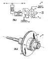
- FIG. 1 illustrates a general perspective view of a Sabatier Reduction system 10 which receives the hydrogen by-product from electrolytic oxygen generation and metabolic carbon dioxide that is concentrated by a molecular sieve bed and reacts them to form methane and water.
- the reactor products are cooled in a heat exchanger 12 where the water product condenses to liquid.
- the liquid water and methane gas are then separated in a rotary phase separator system 14, with the water being delivered to the water bus and the methane released out the vacuum vent duct. Potable water is thereby provided.
- the rotary phase separator system 14 generally includes a rotary drum separator (RDS) 16 and a motor assembly 18.
- the motor assembly 18 drives the RDS 16 through a rotating assembly 20 ( Figure 2 ) in response to a controller 22 (illustrated schematically).
- the RDS preferably operates at two operation speeds. A low speed is used for separating and accumulating water from gas. A higher speed is used for pumping the water once the accumulator is full. It should be understood that other two-phase reduction systems will also benefit from the RDS 16 designed according to the present invention.
- the rotary phase separator system 14 provides for separation of methane gas and liquid water phases at about 10 psia (69 kPa), and pumping of the liquid to a water bus pressure of up to 18 psia (124 kPa). The rotary phase separator system 14 achieves this pumping at less than 100 Watts, and separation at less than 25 Watts.
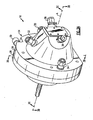
- the RDS 16 includes a housing assembly 24 within which the rotating assembly 20 ( Figure 2 ) rotates about an axis of rotation A.
- the housing assembly 24 includes a first housing portion 26 and a second housing portion 28 which enclose the rotating assembly 20 and provide passageways for fluid circulation.
- a water outlet tangential port tap 30 is tangential to the housing outer diameter and as such collects the water at maximum velocity head.
- a pressure port 32 provides for identification of a fill level.
- a radial port 34 normal to the rotating assembly 20 rotation serves as a static pressure port.
- a gas outlet port 36 is located along the RDS 16 centerline A and two two-phase inlet ports 38 are located adjacent thereto.
- taps 32T, 34T, 36T may be respectively located in the housing assembly 24 to provide communication with the respective ports 32, 34, 36. That is, the taps 32T, 34T, 36T provide connections with the housing assembly 24 and porting defined therein.
- the internal volume of the separator will hold approximately 170 cc of water when full with a working volume of 70 cc mounted around the rotating assembly 20.
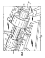
- the rotating assembly 20 is mounted on a first and a second hydrodynamic bearing 40, 42 for rotation about the axis of rotation A.
- the bearings 40, 42 preferably provide both radial and thrust functions.
- the rotating assembly 20 includes a hollow shaft 44 which contains a primary separating impeller 46 and a secondary separating impeller 48.
- the motor provides leak free operation at sub-ambient pressure.
- the hollow shaft 44 contains a gas outlet tube 56 to the gas outlet port 36 located opposite the motor.
- the primary separating impeller 46 includes internal vanes 60 ( Figure 4 ) that facilitate spinning of the two-phase liquid at shaft speed in order to develop the proper 'g' levels to drive the liquid radially outward while allowing the gas to remain adjacent the gas outlet tube 56.
- the secondary separating impeller 48 inside the hollow shaft 44 facilitates separation capability and robustness.
- This secondary separating impeller 48 includes internal passages 62 ( Figure 4 ) that are drilled at an angle to the axis of rotation A to drive liquid (if present) away from an inlet 64 to the gas outlet tube 56 and radially outward.
- the secondary separating impeller 48 also serves as a way to clear away any liquid from near the inlet 64 that may result from a shut-down and restart situation.
- the hollow shaft 44 supports a stepped drum 50 (also illustrated in Figures 2 and 3C ) for accumulation and pumping.
- the stepped drum 50 is mounted on the shaft 44 that is supported by the hydrodynamic bearings 40, 42.
- the stepped drum 50 is stepped such that there is a smaller diameter accumulator section 52 and a relatively large diameter impeller pump section 54.
- the accumulator section 52 is utilized to provide the primary accumulator function.
- the impeller pump section 54 is utilized for the pumping function.
- the aspect ratio of the stepped drum 50 is preferably sized to minimize power for both the accumulating and pumping functions.
- the accumulator section 52 has a relatively small diameter to minimize power losses and uses axial length to accomplish volume for accumulation.
- the impeller pump section 54 of the drum has a larger diameter in order to achieve pumping head but has a small axial length in order to minimize power losses.
- the impeller pump section 54 includes impeller disks 58 each having internal vanes 60 that facilitate the pumping function (also illustrated in Figure 3D ).
- the stepped drum 50 is preferably manufactured from two identical "half" drums assembled opposite to each other which readily facilitates manufacture ( Figure 3C ).
- the stepped drum 50 includes smooth exterior walls on the stepped drum 50 to minimize power losses. Smooth rotating walls of the stepped drums adjacent to smooth stationary walls formed in the housing assembly 24 typically exhibit less drag than non-smooth geometry thereby minimizing the power required to rotate the rotational assembly 20.
- a labyrinth type geometry seal 78 is located on the outer diameter of the accumulator section 52 of stepped drum 50 to minimize the flow of a recirculation loop from the high-pressure side of the pump (at the largest diameter) to the inlet side of the pump. It should be understood that various seal arrangements may be used with the present invention.
- the hollow shaft 44 includes a multitude of shaft gas communication apertures 68 (also illustrated in Figures 4 and 5 ) in communication with the accumulator section 52 and the impeller pump section 54.
- a multitude of liquid communication ports 70 are located adjacent an outer diameter of an impeller shaft section 72 which contains the primary separating impeller 46.
- the liquid communication ports 70 provide communication between the primary separating impeller 46 and the accumulator section 52.
- the liquid communication ports 70 are circumferentially located and angled outward relative to axis A about the hollow shaft 44 adjacent a junction 74 between the impeller shaft section 72 and a central shaft section 76.
- the two-phase flow (water in mostly gas stream) is input into the impeller shaft section 72 of the hollow shaft through the two-phase inlet port 38.
- the two-phase flow is centrifugally flung to the outer diameter of the impeller shaft section 72 that moves the water radially outward through the liquid communication ports 70 while allowing the gas to communicate into the central shaft section 76.
- the primary separating impeller 46 provides ample flow area for the gas while maintaining relatively small clearance to the central shaft section 76 and thence to the inlet 64 of the gas outlet tube 56 to avoid liquid carryover.
- the secondary separating impeller 48 facilitates separation capability and robustness to further minimize liquid (if present) entry into the inlet 64 of the gas outlet tube 56.
- the accumulating function is effectuated inside the accumulator section 52 and the impeller pump section 54 that create a stepped annulus around the center hollow shaft 44.
- the water rotates at essentially shaft speed since it is fully enclosed by the accumulator section 52 and the impeller pump section 54 and has virtually no exposure to stationary housing walls.
- the "full” level is at the OD of the hollow shaft 44.
- the "empty" level of the accumulator will be at the OD of the accumulator section 52.
- the smooth outside walls of the stepped drum 50 minimize power losses. A minimized diameter to length ratio also minimizes power losses.
- the pumping function is accomplished by the impeller pump section 54 which is facilitated by the internal vanes 60 between the impeller disks 58. Once the accumulator section 52 is "full,” the liquid is pumped through the tangential outlet port 34 located at the maximum diameter of the impeller pump section 54 to maximize both static and dynamic head.
- the RDS 16 operates on a two-speed schedule. At low speed, about 1000 rpm, the RDS 16 creates enough of an artificial gravity field to effectively separate the gas and liquid phases.
- the gas outlet port 36 is open when the Sabatier is in process mode generating water; therefore the vent gases flow through the RDS 16 with very little pressure drop.
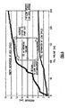
- Pressure port 32, the gas outlet port tap 36 and the radial port 34 ( Figure 3 ) at the drum outer diameter allow monitoring of the liquid level via differential pressure. Applicant has calibrated the pressure vs. volume in both 1-g and 0-g environments. Once the liquid level reaches the high end of the operating range (“full"), the controller ( Figure 1 ) increases the speed of the RDS 16 to about 2000 rpm.
Landscapes
- Chemical & Material Sciences (AREA)
- Chemical Kinetics & Catalysis (AREA)
- Structures Of Non-Positive Displacement Pumps (AREA)
- Centrifugal Separators (AREA)
- Separating Particles In Gases By Inertia (AREA)
Claims (19)
- Rotierende Anordnung (20) für ein rotierendes Phasenseparatorsystem zum Abscheiden einer Flüssigkeit aus einer Zweiphasen-Strömung, wobei die rotierende Anordnung Folgendes aufweist:eine Hohlwelle (44), die entlang einer Rotationsachse (A) gebildet ist und zum Aufnehmen einer Zweiphasen-Strömung ausgebildet ist;einen Speicherbereich (52) zum Akkumulieren von Flüssigkeit, der zum Ausführen einer Rotationsbewegung zusammen mit der Hohlwelle (44) um die Hohlwelle herum angebracht ist, wobei der Speicherbereich mit der Hohlwelle (44) in Verbindung steht und einen ersten Durchmesser bildet; undeinen Laufradpumpenbereich (54) zum Pumpen von Flüssigkeit von der rotierenden Anordnung, der zum Ausführen einer Rotationsbewegung zusammen mit der Hohlwelle um den Speicherbereich (52) herum angebracht ist, wobei der Laufradpumpenbereich (54) einen zweiten Durchmesser bildet, der größer ist als der erste Durchmesser.
- Anordnung nach Anspruch 1,
wobei der Speicherbereich (52) eine erste axiale Länge bildet und der Laufradpumpenbereich eine zweite axiale Länge bildet, die geringer ist als die erste axiale Länge. - Anordnung nach Anspruch 1 oder 2,
weiterhin aufweisend ein primäres Abscheide-Laufrad (46), das im Inneren der Hohlwelle (44) zusammen mit dieser drehbar angebracht ist, wobei das primäre Abscheide-Laufrad mit dem Speicherbereich in Verbindung steht. - Anordnung nach Anspruch 3,
wobei das primäre Abscheide-Laufrad (46) in einem Laufradwellenbereich der Hohlwelle (44) angebracht ist, wobei der Laufradwellenbereich mit einem zentralen Wellenbereich der Hohlwelle in Verbindung steht und wobei der zentrale Wellenbereich mehrere Wellen-Gasverbindungsöffnungen (68) in Verbindung mit dem Speicherbereich (52) aufweist. - Anordnung nach Anspruch 4,
weiterhin aufweisend einen Zweiphasen-Einlass (38) in Verbindung mit dem Laufradwellenbereich. - Anordnung nach einem der vorausgehenden Ansprüche,
weiterhin aufweisend ein Gasaustrittsrohr (56), das im Inneren der Hohlwelle angebracht ist, wobei das Gasaustrittsrohr mit einer Gasaustrittsöffnung (36) in Verbindung steht, die entlang der Rotationsachse gebildet ist. - Anordnung nach Anspruch 6,
wobei das Gasaustrittsrohr einen Einlass (64) aufweist, der gegenüber der Gasaustrittsöffnung entlang der Rotationsachse angebracht ist. - Anordnung nach Anspruch 7.
weiterhin aufweisend ein sekundäres Abscheide-Laufrad (48), das in der Hohlwelle (44) zusammen mit dieser drehbar angebracht ist, wobei das sekundäre Abscheide-Laufrad benachbart dem Einlass (64) in das Gasaustrittsrohr (56) angebracht ist. - Anordnung nach einem der vorausgehenden Ansprüche,
wobei der Laufradpumpenbereich eine Laufradscheibe (68) und eine Vielzahl von Laufradschaufeln (60) aufweist, die an der Laufradscheibe in einer radialen Anordnung um die Rotationsachse angebracht sind. - Anordnung nach Anspruch 9,
weiterhin aufweisend eine Flüssigkeitsaustrittsöffnung (30) tangential zu dem Laufradpumpenbereich. - Rotierendes Phasenseparatorsystem zum Abscheiden von Flüssigkeit aus einer Zweiphasen-Strömung, aufweisend:ein Gehäuse (24);ein hydrodynamisches Lager (40, 42), das in dem Gehäuse angebracht ist;eine rotierende Anordnung (20) nach Anspruch 1, die in dem hydrodynamischen Lager zur Ausführung einer Rotationsbewegung in dem Gehäuse angebracht ist, wobei die rotierende Anordnung weiterhin ein in der Hohlwelle angebrachtes Gasaustrittsrohr (56) und einen primäres Abscheide-Laufrad (46) aufweist, das in einem Laufradwellenbereich der Hohlwelle zusammen mit dieser drehbar angebracht ist;eine Zweiphasen-Eintrittsöffnung (38) in dem Gehäuse und in Verbindung mit dem Laufradpumpenbereich; undeine Gasaustrittsöffnung (36) in dem Gehäuse entlang der Rotationsachse, wobei die Gasaustrittsöffnung mit dem Gasaustrittsrohr (56) in Verbindung steht.
- System nach Anspruch 11,
wobei sich der Laufradpumpenbereich (54) radial von dem Speicherbereich (52) weg erstreckt, wobei der Laufradpumpenbereich eine Laufradscheibe (68) und eine Vielzahl von Laufradschaufeln (60) aufweist, die an der Laufradscheibe in einer radialen Anordnung um die Rotationsachse angebracht sind, so dass eine Stufen-Trommel (50) gebildet ist. - System nach Anspruch 12,
weiterhin aufweisend eine Austrittsöffnung (30) in dem Gehäuse tangential zu dem Laufradpumpenbereich (54). - System nach Anspruch 11, 12 oder 13, weiterhin aufweisend:einen Motor (18), der auf der Hohlwelle (44) angebracht ist; undeine Steuerung (22) in Verbindung mit dem Motor zum Antreiben der Hohlwelle mit einer Vielzahl von Drehzahlen, wobei die Vielzahl von Drehzahlen eine Akkumulier-Drehzahl und eine Pump-Drehzahl beinhalten.
- Verfahren zum Rückgewinnen einer Flüssigkeit aus einer Zweiphasen-Strömung, wobei das Verfahren folgende Schritte aufweist:(1) Drehen der rotierenden Anordnung (20) nach Anspruch 1 um die Rotationsachse (A) mit einer ersten Drehzahl;(2) Einleiten der Zweiphasen-Strömung in die rotierende Hohlwelle (44);(3) Trennen der Zweiphasen-Strömung derart, dass eine Flüssigkeitskomponente relativ zu der Rotationsachse (A) radial außen in dem um die Hohlwelle (44) herum angebrachten Speicherbereich (52) zentrifugal abgeschieden wird;(4) Sammeln einer Gaskomponente im Allgemeinen entlang der Rotationsachse (A);(5) Akkumulieren der Flüssigkeitskomponente in dem Speicherbereich (52);(6) selektives Drehen der Hohlwelle (44) um die Rotationsachse (A) mit einer zweiten Drehzahl, die höher ist als die erste Drehzahl; und(7) Abpumpen der Flüssigkeitskomponente mit dem um den Speicherbereich (52) angebrachten Laufradpumpenbereich (54) in Abhängigkeit von dem Schritt (6).
- Verfahren nach Anspruch 15,
wobei der Schritt (3) ferner Folgendes beinhaltet:(a) Füllen des Speicherbereichs (52) mit der Flüssigkeitskomponente von einem Außendurchmesser des Speicherbereichs (52) her in Richtung auf die Rotationsachse (A); und(b) Treiben der Gaskomponente radial nach innen zur Rotationsachse (A) hin. - Verfahren nach Anspruch 15 oder 16,
wobei der Schritt (4) ferner Folgendes beinhaltet:(c) Übertragen der Gaskomponente axial entlang der Rotationsachse (A) durch ein in der Hohlwelle (44) angebrachtes Gasaustrittsrohr (56). - Verfahren nach Anspruch 15, 16 oder 17,
wobei der Schritt (2) ferner Folgendes beinhaltet:(a) Einleiten der Zweiphasen-Strömung in den Laufradwellenbereich (72) der rotierenden Hohlwelle (44), der einen größeren Durchmesser als ein zentraler Wellenbereich der rotierenden Hohlwelle (44) bildet, wobei der Laufradwellenbereich (72) das primäre Abscheide-Laufrad (46) beinhaltet, das sich zusammen mit der rotierenden Hohlwelle (44) dreht. - Verfahren nach Anspruch 15, 16, 17 oder 18,
wobei der Schritt (7) ferner Folgendes beinhaltet:(a) Pumpen der Flüssigkeitskomponente durch eine Austrittsöffnung (30), die einem Außendurchmesser des um den Speicherbereich (52) herum angebrachten Laufradpumpenbereichs (54) benachbart tangential angebracht ist.
Applications Claiming Priority (1)
| Application Number | Priority Date | Filing Date | Title |
|---|---|---|---|
| US11/429,859 US7628836B2 (en) | 2006-05-08 | 2006-05-08 | Rotary drum separator system |
Publications (2)
| Publication Number | Publication Date |
|---|---|
| EP1854528A1 EP1854528A1 (de) | 2007-11-14 |
| EP1854528B1 true EP1854528B1 (de) | 2010-06-30 |
Family
ID=37944268
Family Applications (1)
| Application Number | Title | Priority Date | Filing Date |
|---|---|---|---|
| EP07250968A Active EP1854528B1 (de) | 2006-05-08 | 2007-03-08 | System zur Phasentrennung mittels Rotation |
Country Status (4)
| Country | Link |
|---|---|
| US (1) | US7628836B2 (de) |
| EP (1) | EP1854528B1 (de) |
| JP (1) | JP4700635B2 (de) |
| DE (1) | DE602007007394D1 (de) |
Families Citing this family (35)
| Publication number | Priority date | Publication date | Assignee | Title |
|---|---|---|---|---|
| US8075668B2 (en) | 2005-03-29 | 2011-12-13 | Dresser-Rand Company | Drainage system for compressor separators |
| CA2664121C (en) | 2006-09-19 | 2014-05-27 | William C. Maier | Rotary separator drum seal |
| US8302779B2 (en) | 2006-09-21 | 2012-11-06 | Dresser-Rand Company | Separator drum and compressor impeller assembly |
| MX2009003177A (es) | 2006-09-25 | 2009-04-03 | Dresser Rand Co | Bobina conectora axialmente movil. |
| EP2066988A4 (de) | 2006-09-25 | 2012-01-04 | Dresser Rand Co | Kopplungsüberwachungssystem |
| EP2066983B1 (de) | 2006-09-25 | 2013-12-11 | Dresser-Rand Company | Kompressorbefestigungssystem |
| MX2009003175A (es) | 2006-09-25 | 2009-04-03 | Dresser Rand Co | Cubierta de acceso para bobina conectora presurizada. |
| EP2066453A4 (de) | 2006-09-25 | 2012-04-04 | Dresser Rand Co | Flüssigkeitsdetektor für flüssigkeitstrenngeräte |
| MX2009003255A (es) | 2006-09-26 | 2009-04-07 | Dresser Rand Co | Dispositivo separador de fluido estatico mejorado. |
| US8408879B2 (en) | 2008-03-05 | 2013-04-02 | Dresser-Rand Company | Compressor assembly including separator and ejector pump |
| US7846228B1 (en) * | 2008-03-10 | 2010-12-07 | Research International, Inc. | Liquid particulate extraction device |
| US8062400B2 (en) | 2008-06-25 | 2011-11-22 | Dresser-Rand Company | Dual body drum for rotary separators |
| US8079805B2 (en) | 2008-06-25 | 2011-12-20 | Dresser-Rand Company | Rotary separator and shaft coupler for compressors |
| US7922218B2 (en) | 2008-06-25 | 2011-04-12 | Dresser-Rand Company | Shear ring casing coupler device |
| US8147581B1 (en) * | 2009-01-29 | 2012-04-03 | Watterman Jr John K | Gas solid mixture separator |
| US8210804B2 (en) | 2009-03-20 | 2012-07-03 | Dresser-Rand Company | Slidable cover for casing access port |
| US8087901B2 (en) | 2009-03-20 | 2012-01-03 | Dresser-Rand Company | Fluid channeling device for back-to-back compressors |
| US8061972B2 (en) | 2009-03-24 | 2011-11-22 | Dresser-Rand Company | High pressure casing access cover |
| EP2478229B1 (de) * | 2009-09-15 | 2020-02-26 | Dresser-Rand Company | Kompakte trennvorrichtung auf basis erhöhter dichte |
| BR112012020085B1 (pt) | 2010-02-10 | 2020-12-01 | Dresser-Rand Company | aparelho de coleta para um separador e método de separação |
| WO2012009158A2 (en) * | 2010-07-15 | 2012-01-19 | Dresser-Rand Company | Enhanced in-line rotary separator |
| WO2012009159A2 (en) * | 2010-07-15 | 2012-01-19 | Dresser-Rand Company | Radial vane pack for rotary separators |
| US8657935B2 (en) | 2010-07-20 | 2014-02-25 | Dresser-Rand Company | Combination of expansion and cooling to enhance separation |
| WO2012012143A2 (en) | 2010-07-21 | 2012-01-26 | Dresser-Rand Company | Multiple modular in-line rotary separator bundle |
| JP5936144B2 (ja) | 2010-09-09 | 2016-06-15 | ドレッサー ランド カンパニーDresser−Rand Company | 洗浄可能に制御された排水管 |
| US8994237B2 (en) | 2010-12-30 | 2015-03-31 | Dresser-Rand Company | Method for on-line detection of liquid and potential for the occurrence of resistance to ground faults in active magnetic bearing systems |
| EP2659277B8 (de) | 2010-12-30 | 2018-05-23 | Dresser-Rand Company | Verfahren zur online-erkennung von bodenwiderstandsfehlern in aktiven magnetlagersystemen |
| KR101192895B1 (ko) | 2011-01-04 | 2012-10-18 | 조기환 | 회전판 고형물 합체 분리기용 회전 로터 |
| WO2012138545A2 (en) | 2011-04-08 | 2012-10-11 | Dresser-Rand Company | Circulating dielectric oil cooling system for canned bearings and canned electronics |
| US20120259025A1 (en) * | 2011-04-11 | 2012-10-11 | Qingchun Zhao | Method and Systems Thereof of Ecologically Carbon Dioxide-Neutral Methanation |
| WO2012166236A1 (en) | 2011-05-27 | 2012-12-06 | Dresser-Rand Company | Segmented coast-down bearing for magnetic bearing systems |
| US8851756B2 (en) | 2011-06-29 | 2014-10-07 | Dresser-Rand Company | Whirl inhibiting coast-down bearing for magnetic bearing systems |
| SG11202102768SA (en) * | 2018-09-19 | 2021-04-29 | Haven Tech Solutions Llc | Method and device for separating a lighter density fluid from a heavier density fluid |
| US11433337B2 (en) | 2019-08-30 | 2022-09-06 | Paragon Space Development Corporation | Two-phase separator device for removing condensate or particulate from a gas stream |
| DE102020118595A1 (de) * | 2020-07-14 | 2022-01-20 | Alfred Kärcher SE & Co. KG | Saug-Reinigungsgerät und Verfahren zum Betreiben eines Saug-Reinigungsgeräts |
Family Cites Families (8)
| Publication number | Priority date | Publication date | Assignee | Title |
|---|---|---|---|---|
| JPS5324602A (en) * | 1976-08-20 | 1978-03-07 | Kubota Ltd | Open inpeller type pump |
| GB1531700A (en) | 1977-08-30 | 1978-11-08 | Kobe Inc | Pitot compressors |
| SE469040B (sv) * | 1991-09-03 | 1993-05-03 | Flygt Ab Itt | Centrifugalpumphjul foer pump avsedd att pumpa vaetskor innehaallande fasta partiklar |
| JP2555518Y2 (ja) * | 1991-09-09 | 1997-11-26 | 応研精工株式会社 | インペラーポンプ |
| US5244479A (en) | 1993-03-15 | 1993-09-14 | United Technologies Corporation | Liquid/gas separator for soapy liquid |
| US5693125A (en) * | 1995-12-22 | 1997-12-02 | United Technologies Corporation | Liquid-gas separator |
| JP3993730B2 (ja) * | 2000-03-02 | 2007-10-17 | 日本電産サンキョー株式会社 | ポンプ装置用のインペラ及びポンプ装置 |
| US6547862B2 (en) | 2001-07-02 | 2003-04-15 | Hamilton Sundstrand | Rotary phase separator with integral accumulator and outlet valve |
-
2006
- 2006-05-08 US US11/429,859 patent/US7628836B2/en active Active
-
2007
- 2007-02-27 JP JP2007046347A patent/JP4700635B2/ja not_active Expired - Fee Related
- 2007-03-08 EP EP07250968A patent/EP1854528B1/de active Active
- 2007-03-08 DE DE602007007394T patent/DE602007007394D1/de active Active
Also Published As
| Publication number | Publication date |
|---|---|
| DE602007007394D1 (de) | 2010-08-12 |
| JP4700635B2 (ja) | 2011-06-15 |
| US7628836B2 (en) | 2009-12-08 |
| JP2007301549A (ja) | 2007-11-22 |
| EP1854528A1 (de) | 2007-11-14 |
| US20070256398A1 (en) | 2007-11-08 |
Similar Documents
| Publication | Publication Date | Title |
|---|---|---|
| US7628836B2 (en) | Rotary drum separator system | |
| US6601651B2 (en) | Downhole gas compression | |
| EP2427632B1 (de) | Gasresistente unterwasserpumpe | |
| CN106150577B (zh) | 用于通过有机朗肯循环产生能量的设备和方法 | |
| CN102844572B (zh) | 改进型泵 | |
| JP2013100817A (ja) | ギアボックス、および空気とオイルの混合物からオイルを除去する方法 | |
| JPH11507425A (ja) | 多段の2相タービン | |
| US20100284796A1 (en) | Pump | |
| JP6496010B2 (ja) | 熱エネルギーを変換する装置及び方法 | |
| NO337108B1 (no) | Flerfase trykkforsterkningspumpe | |
| CN103608550B (zh) | 废热发电装置 | |
| CN104471209A (zh) | 可变容量型增压器以及可变容量型增压器用壳体的制造方法 | |
| US6354800B1 (en) | Dual pressure Euler turbine | |
| CN101652549A (zh) | 旋转装置 | |
| WO2003046336A1 (en) | Downhole pump assembly and method of recovering well fluids | |
| CN101198792B (zh) | 液环式压缩机 | |
| US9228588B2 (en) | Turbomachine component temperature control | |
| CN103244438B (zh) | 牵引级复合分子泵 | |
| JPWO2016185570A1 (ja) | 遠心圧縮機 | |
| Barone et al. | Rotary drum separator system | |
| KR20110043519A (ko) | 고체, 액체, 증기 및 가스를 동시에 전달하기 위한 슬러지 리액터 펌프 | |
| JP6663269B2 (ja) | 圧縮機 | |
| CN116557300B (zh) | 一种泵 | |
| CN201330759Y (zh) | 一种旋转动力式多相增压泵 | |
| JP2007154667A (ja) | フランシス形水力機械 |
Legal Events
| Date | Code | Title | Description |
|---|---|---|---|
| PUAI | Public reference made under article 153(3) epc to a published international application that has entered the european phase |
Free format text: ORIGINAL CODE: 0009012 |
|
| 17P | Request for examination filed |
Effective date: 20070807 |
|
| AK | Designated contracting states |
Kind code of ref document: A1 Designated state(s): AT BE BG CH CY CZ DE DK EE ES FI FR GB GR HU IE IS IT LI LT LU LV MC MT NL PL PT RO SE SI SK TR |
|
| AX | Request for extension of the european patent |
Extension state: AL BA HR MK YU |
|
| 17Q | First examination report despatched |
Effective date: 20071221 |
|
| AKX | Designation fees paid |
Designated state(s): DE FR GB |
|
| GRAP | Despatch of communication of intention to grant a patent |
Free format text: ORIGINAL CODE: EPIDOSNIGR1 |
|
| GRAS | Grant fee paid |
Free format text: ORIGINAL CODE: EPIDOSNIGR3 |
|
| GRAA | (expected) grant |
Free format text: ORIGINAL CODE: 0009210 |
|
| AK | Designated contracting states |
Kind code of ref document: B1 Designated state(s): DE FR GB |
|
| REG | Reference to a national code |
Ref country code: GB Ref legal event code: FG4D |
|
| REF | Corresponds to: |
Ref document number: 602007007394 Country of ref document: DE Date of ref document: 20100812 Kind code of ref document: P |
|
| PLBE | No opposition filed within time limit |
Free format text: ORIGINAL CODE: 0009261 |
|
| STAA | Information on the status of an ep patent application or granted ep patent |
Free format text: STATUS: NO OPPOSITION FILED WITHIN TIME LIMIT |
|
| 26N | No opposition filed |
Effective date: 20110331 |
|
| REG | Reference to a national code |
Ref country code: DE Ref legal event code: R097 Ref document number: 602007007394 Country of ref document: DE Effective date: 20110330 |
|
| PGFP | Annual fee paid to national office [announced via postgrant information from national office to epo] |
Ref country code: DE Payment date: 20130306 Year of fee payment: 7 |
|
| REG | Reference to a national code |
Ref country code: DE Ref legal event code: R119 Ref document number: 602007007394 Country of ref document: DE |
|
| REG | Reference to a national code |
Ref country code: DE Ref legal event code: R119 Ref document number: 602007007394 Country of ref document: DE Effective date: 20141001 |
|
| PG25 | Lapsed in a contracting state [announced via postgrant information from national office to epo] |
Ref country code: DE Free format text: LAPSE BECAUSE OF NON-PAYMENT OF DUE FEES Effective date: 20141001 |
|
| REG | Reference to a national code |
Ref country code: FR Ref legal event code: PLFP Year of fee payment: 10 |
|
| REG | Reference to a national code |
Ref country code: FR Ref legal event code: PLFP Year of fee payment: 11 |
|
| REG | Reference to a national code |
Ref country code: FR Ref legal event code: PLFP Year of fee payment: 12 |
|
| P01 | Opt-out of the competence of the unified patent court (upc) registered |
Effective date: 20230522 |
|
| PGFP | Annual fee paid to national office [announced via postgrant information from national office to epo] |
Ref country code: GB Payment date: 20260219 Year of fee payment: 20 |
|
| PGFP | Annual fee paid to national office [announced via postgrant information from national office to epo] |
Ref country code: FR Payment date: 20260219 Year of fee payment: 20 |