EP1854500A1 - Treatment tool inserting/withdrawing auxiliary device - Google Patents
Treatment tool inserting/withdrawing auxiliary device Download PDFInfo
- Publication number
- EP1854500A1 EP1854500A1 EP07009065A EP07009065A EP1854500A1 EP 1854500 A1 EP1854500 A1 EP 1854500A1 EP 07009065 A EP07009065 A EP 07009065A EP 07009065 A EP07009065 A EP 07009065A EP 1854500 A1 EP1854500 A1 EP 1854500A1
- Authority
- EP
- European Patent Office
- Prior art keywords
- catheter
- treatment tool
- curvable
- auxiliary device
- tool inserting
- Prior art date
- Legal status (The legal status is an assumption and is not a legal conclusion. Google has not performed a legal analysis and makes no representation as to the accuracy of the status listed.)
- Granted
Links
- 238000003780 insertion Methods 0.000 claims description 32
- 230000037431 insertion Effects 0.000 claims description 32
- 239000011347 resin Substances 0.000 claims description 22
- 229920005989 resin Polymers 0.000 claims description 22
- 230000000007 visual effect Effects 0.000 claims description 7
- 238000004891 communication Methods 0.000 claims description 3
- 239000003550 marker Substances 0.000 claims description 3
- 239000002872 contrast media Substances 0.000 description 38
- 210000000013 bile duct Anatomy 0.000 description 24
- 238000000034 method Methods 0.000 description 23
- 238000010586 diagram Methods 0.000 description 20
- 230000002183 duodenal effect Effects 0.000 description 13
- 210000000277 pancreatic duct Anatomy 0.000 description 7
- 238000009548 contrast radiography Methods 0.000 description 6
- 230000000694 effects Effects 0.000 description 5
- 239000002184 metal Substances 0.000 description 3
- 239000004677 Nylon Substances 0.000 description 2
- 229920001778 nylon Polymers 0.000 description 2
- 239000004810 polytetrafluoroethylene Substances 0.000 description 2
- 229920001343 polytetrafluoroethylene Polymers 0.000 description 2
- 210000005070 sphincter Anatomy 0.000 description 2
- JOYRKODLDBILNP-UHFFFAOYSA-N Ethyl urethane Chemical compound CCOC(N)=O JOYRKODLDBILNP-UHFFFAOYSA-N 0.000 description 1
- 230000005540 biological transmission Effects 0.000 description 1
- 238000003745 diagnosis Methods 0.000 description 1
- 210000003238 esophagus Anatomy 0.000 description 1
- 229920000840 ethylene tetrafluoroethylene copolymer Polymers 0.000 description 1
- 238000002594 fluoroscopy Methods 0.000 description 1
- 239000000314 lubricant Substances 0.000 description 1
- 239000000463 material Substances 0.000 description 1
- 238000012986 modification Methods 0.000 description 1
- 230000004048 modification Effects 0.000 description 1
- 229920009441 perflouroethylene propylene Polymers 0.000 description 1
- 229920011301 perfluoro alkoxyl alkane Polymers 0.000 description 1
- 229920002635 polyurethane Polymers 0.000 description 1
- 239000004814 polyurethane Substances 0.000 description 1
- 229910001220 stainless steel Inorganic materials 0.000 description 1
- 239000010935 stainless steel Substances 0.000 description 1
- 238000013519 translation Methods 0.000 description 1
Images


Classifications
-
- A—HUMAN NECESSITIES
- A61—MEDICAL OR VETERINARY SCIENCE; HYGIENE
- A61M—DEVICES FOR INTRODUCING MEDIA INTO, OR ONTO, THE BODY; DEVICES FOR TRANSDUCING BODY MEDIA OR FOR TAKING MEDIA FROM THE BODY; DEVICES FOR PRODUCING OR ENDING SLEEP OR STUPOR
- A61M25/00—Catheters; Hollow probes
- A61M25/01—Introducing, guiding, advancing, emplacing or holding catheters
- A61M25/0105—Steering means as part of the catheter or advancing means; Markers for positioning
- A61M25/0133—Tip steering devices
- A61M25/0147—Tip steering devices with movable mechanical means, e.g. pull wires
-
- A—HUMAN NECESSITIES
- A61—MEDICAL OR VETERINARY SCIENCE; HYGIENE
- A61M—DEVICES FOR INTRODUCING MEDIA INTO, OR ONTO, THE BODY; DEVICES FOR TRANSDUCING BODY MEDIA OR FOR TAKING MEDIA FROM THE BODY; DEVICES FOR PRODUCING OR ENDING SLEEP OR STUPOR
- A61M25/00—Catheters; Hollow probes
- A61M25/0043—Catheters; Hollow probes characterised by structural features
- A61M25/005—Catheters; Hollow probes characterised by structural features with embedded materials for reinforcement, e.g. wires, coils, braids
- A61M25/0053—Catheters; Hollow probes characterised by structural features with embedded materials for reinforcement, e.g. wires, coils, braids having a variable stiffness along the longitudinal axis, e.g. by varying the pitch of the coil or braid
-
- A—HUMAN NECESSITIES
- A61—MEDICAL OR VETERINARY SCIENCE; HYGIENE
- A61M—DEVICES FOR INTRODUCING MEDIA INTO, OR ONTO, THE BODY; DEVICES FOR TRANSDUCING BODY MEDIA OR FOR TAKING MEDIA FROM THE BODY; DEVICES FOR PRODUCING OR ENDING SLEEP OR STUPOR
- A61M25/00—Catheters; Hollow probes
- A61M25/01—Introducing, guiding, advancing, emplacing or holding catheters
- A61M25/0105—Steering means as part of the catheter or advancing means; Markers for positioning
- A61M25/0133—Tip steering devices
- A61M25/0141—Tip steering devices having flexible regions as a result of using materials with different mechanical properties
-
- A—HUMAN NECESSITIES
- A61—MEDICAL OR VETERINARY SCIENCE; HYGIENE
- A61M—DEVICES FOR INTRODUCING MEDIA INTO, OR ONTO, THE BODY; DEVICES FOR TRANSDUCING BODY MEDIA OR FOR TAKING MEDIA FROM THE BODY; DEVICES FOR PRODUCING OR ENDING SLEEP OR STUPOR
- A61M25/00—Catheters; Hollow probes
- A61M25/0043—Catheters; Hollow probes characterised by structural features
- A61M2025/006—Catheters; Hollow probes characterised by structural features having a special surface topography or special surface properties, e.g. roughened or knurled surface
-
- A—HUMAN NECESSITIES
- A61—MEDICAL OR VETERINARY SCIENCE; HYGIENE
- A61M—DEVICES FOR INTRODUCING MEDIA INTO, OR ONTO, THE BODY; DEVICES FOR TRANSDUCING BODY MEDIA OR FOR TAKING MEDIA FROM THE BODY; DEVICES FOR PRODUCING OR ENDING SLEEP OR STUPOR
- A61M25/00—Catheters; Hollow probes
- A61M25/01—Introducing, guiding, advancing, emplacing or holding catheters
- A61M25/0105—Steering means as part of the catheter or advancing means; Markers for positioning
- A61M25/0133—Tip steering devices
- A61M2025/0163—Looped catheters
-
- A—HUMAN NECESSITIES
- A61—MEDICAL OR VETERINARY SCIENCE; HYGIENE
- A61M—DEVICES FOR INTRODUCING MEDIA INTO, OR ONTO, THE BODY; DEVICES FOR TRANSDUCING BODY MEDIA OR FOR TAKING MEDIA FROM THE BODY; DEVICES FOR PRODUCING OR ENDING SLEEP OR STUPOR
- A61M25/00—Catheters; Hollow probes
- A61M25/0043—Catheters; Hollow probes characterised by structural features
- A61M25/0045—Catheters; Hollow probes characterised by structural features multi-layered, e.g. coated
-
- A—HUMAN NECESSITIES
- A61—MEDICAL OR VETERINARY SCIENCE; HYGIENE
- A61M—DEVICES FOR INTRODUCING MEDIA INTO, OR ONTO, THE BODY; DEVICES FOR TRANSDUCING BODY MEDIA OR FOR TAKING MEDIA FROM THE BODY; DEVICES FOR PRODUCING OR ENDING SLEEP OR STUPOR
- A61M25/00—Catheters; Hollow probes
- A61M25/0043—Catheters; Hollow probes characterised by structural features
- A61M25/0054—Catheters; Hollow probes characterised by structural features with regions for increasing flexibility
Definitions
- the present invention relates to a treatment tool inserting/withdrawing auxiliary device.
- a contrast medium injecting catheter for facilitating these operations is disclosed in Japanese Unexamined Patent Application, First Publication No. 2002-272675 and Published Japanese Translation No. 2004-532668 of PCT International Publication.
- a medical procedure other than for the bile duct system there is an attempt to facilitate the manipulation by means of a catheter as disclosed in U.S. Patent No. 6,659,981 .
- the distal end of the catheter is curved to some extent, the positioning operation by the endoscope insertion portion can be assisted.
- a guide wire having at least twice the length of the contrast medium injecting catheter is inserted into the contrast medium injecting catheter, and the contrast medium injecting catheter is withdrawn from the endoscope through the guide wire. Then, the treatment tool to be used is inserted into the endoscope along the guide wire, and moved to the target site.
- the distal end of the catheter must be positioned by a skilled manoeuvering of the endoscope even though the distal end of the catheter is curved to some extent. As a result, a high skill for positioning is required for the operator.
- the treatment tools when plural treatment tools are used, the treatment tools must be inserted and withdrawn using a guide wire; therefore, the exchanging operation between the treatment tools is complicated, and makes the operation time longer.
- An object of the present invention is to provide a device capable of readily performing cannulation while the distal end of an endoscope insertion portion is positioned with respect to the duodenal papilla, and capable of exchanging treatment tools without using a guide wire.
- a treatment tool inserting/withdrawing auxiliary device includes: a catheter through which a treatment tool for an endoscope is to be inserted, and which is insertable into a channel of a flexible endoscope; an operation wire which is inserted into the catheter, and is supported on a distal end or the vicinity of the catheter; an operation portion which moves the operation wire back and forth with respect to the catheter; and a curvable portion which is provided on the catheter and is curved by a back and forth movement of the operation wire, wherein the curvable portion is curvable within a range between 0 to 170 degree of a curved angle, assuming that the curved angle is an angle defined by axial centers of the proximal end and the distal end of the curvable portion, and the curved angle becomes 0 when the axial centers of the proximal end and the distal end are approximately on the same line having the curvable portion therebetween.
- a second aspect of the present invention is the treatment tool inserting/withdrawing auxiliary device according to the first aspect of the present invention, wherein the operation wire is partially exposed to the outside of the catheter to form an exposed portion, a length of the exposed portion varies according to a moved amount of the operation wire to the proximal side of the catheter by the operation portion, and the curvable portion is curved according to the length of the exposed portion.
- a third aspect of the present invention is the treatment tool inserting/withdrawing auxiliary device according to the first aspect of the present invention, wherein a coil layer is arranged at least on the curvable portion of the catheter.
- a fourth aspect of the present invention is the treatment tool inserting/withdrawing auxiliary device according to the third aspect of the present invention, wherein a mesh pipe layer is continually provided on the proximal end of the coil layer, and arranged on the catheter.
- a fifth aspect of the present invention is the treatment tool inserting/withdrawing auxiliary device according to the third aspect of the present invention, wherein a fluororesin layer is arranged at least on the inside of the coil layer of the catheter.
- a sixth aspect of the present invention is the treatment tool inserting/withdrawing auxiliary device according to the third aspect of the present invention, wherein a pitch on the proximal side of the coil layer is greater than a pitch of the distal side thereof.
- a seventh aspect of the present invention is the treatment tool inserting/withdrawing auxiliary device according to the first aspect of the present invention, wherein a visual check marker for identifying a length from the distal end is provided on the distal end of the catheter.
- An eighth aspect of the present invention is the treatment tool inserting/withdrawing auxiliary device according to the first aspect of the present invention, further including a treatment tool insertion/withdrawal port which is provided in communication with the catheter, and through which the treatment tool for an endoscope is to be inserted/withdrawn.
- a ninth aspect of the present invention is the treatment tool inserting/withdrawing auxiliary device according to the eighth aspect of the present invention, wherein one end of the operation wire is connected to the operation portion, and the other end side is folded on the distal end of the catheter and arranged toward the proximal side of the catheter.
- a tenth aspect of the present invention is the treatment tool inserting/withdrawing auxiliary device according to the ninth aspect of the present invention, wherein the operation portion is detachably connected to the catheter.
- An eleventh aspect of the present invention is the treatment tool inserting/withdrawing auxiliary device according to the first aspect of the present invention, wherein a length of the exposed portion varies within a range of more than 10mm and less than 40mm, by a back-and-forth moving operation of the operation portion.
- a twelfth aspect of the present invention is the treatment tool inserting/withdrawing auxiliary device according to the first aspect of the present invention, wherein the distal end of the catheter is provided with an index at least a part of which is formed to be gradually wider toward the proximal side.
- a thirteenth aspect of the present invention is the treatment tool inserting/withdrawing auxiliary device according to the first aspect of the present invention, wherein at least the curvable portion of the catheter comprises a transparent resin.
- a fourteenth aspect of the present invention is the treatment tool inserting/withdrawing auxiliary device according to the first aspect of the present invention, wherein a surface of the proximal side of the catheter is provided with convex portions or concavities.
- the distal end of the catheter projecting from the channel of the endoscope can be brought close to the proximal portion of the curvable catheter so that the direction of the distal end of the catheter and the direction of the proximal portion define a predetermined angle
- the direction of the distal end of the catheter can be matched with the direction of insertion by merely curving the curvable portion of the curvable catheter. Accordingly, without requiring a high skill for positioning, cannulation can be readily performed in a condition where the distal end of the endoscope insertion portion is fixed.
- FIG. 1 is an overall schematic diagram showing a treatment tool inserting/withdrawing auxiliary device according to a first embodiment.
- FIG. 2 is a main part side view showing a curvable catheter of the treatment tool inserting/withdrawing auxiliary device according to the first embodiment.
- FIG. 3 is a cross-sectional view taken along the line A-A' in FIG. 2.
- FIG. 4 is a cross-sectional view taken along the line B-B' in FIG. 2.
- FIG. 5 is an internal configuration diagram of the main part showing the curvable catheter of the treatment tool inserting/withdrawing auxiliary device according to the first embodiment.
- FIG. 6 is an internal configuration diagram of the main part showing the curvable catheter of the treatment tool inserting/withdrawing auxiliary device according to the first embodiment.
- FIG. 7 is an internal configuration diagram of the main part showing a modified example of the curvable catheter of the treatment tool inserting/withdrawing auxiliary device according to the first embodiment.
- FIG. 8 is an explanatory diagram showing the curved condition of the curvable catheter of the treatment tool inserting/withdrawing auxiliary device according to the first embodiment.
- FIG. 9 is a cross-sectional view showing a branched portion of the treatment tool inserting/withdrawing auxiliary device according to the first embodiment.
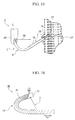
- FIG. 10 is a cross-sectional view showing a modified example of the branched portion of the treatment tool inserting/withdrawing auxiliary device according to the first embodiment.
- FIG. 11 is an explanatory diagram showing a medical procedure through an endoscope by the treatment tool inserting/withdrawing auxiliary device according to the first embodiment.
- FIG. 12 is an explanatory diagram showing the medical procedure through the endoscope by the treatment tool inserting/withdrawing auxiliary device according to the first embodiment.
- FIG. 13 is an explanatory diagram showing the medical procedure through the endoscope by the treatment tool inserting/withdrawing auxiliary device according to the first embodiment.
- FIG. 14 is an explanatory diagram showing the medical procedure through the endoscope by the treatment tool inserting/withdrawing auxiliary device according to the first embodiment.
- FIG. 15 is an explanatory diagram showing the medical procedure through the endoscope by the treatment tool inserting/withdrawing auxiliary device according to the first embodiment.
- FIG. 16 is an internal configuration diagram of the main part showing the curvable catheter of the treatment tool inserting/withdrawing auxiliary device according to a second embodiment.
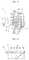
- FIG. 17 is an explanatory diagram showing a curved condition of the curvable catheter of the treatment tool inserting/withdrawing auxiliary device according to a third embodiment.
- FIG. 18 is a main part plan view showing the curvable catheter of the treatment tool inserting/withdrawing auxiliary device according to the third embodiment.
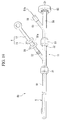
- FIG. 19 is an overall schematic diagram showing the treatment tool inserting/withdrawing auxiliary device according to a fourth embodiment.
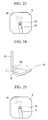
- FIG. 20 is a main part plan view showing the curvable catheter of the treatment tool inserting/withdrawing auxiliary device according to a fifth embodiment.
- FIG. 21 is a main part plan view showing a modified example of the curvable catheter of the treatment tool inserting/withdrawing auxiliary device according to the fifth embodiment.
- FIG. 22 is an explanatory diagram showing a curved condition of the curvable catheter of the treatment tool inserting/withdrawing auxiliary device according to the fifth embodiment.
- FIG. 23 is an explanatory diagram showing a medical procedure through an endoscope by the treatment tool inserting/withdrawing auxiliary device according to the fifth embodiment.
- FIG. 24 is an explanatory diagram showing the curved condition of the treatment tool inserting/withdrawing auxiliary device according to the fifth embodiment.
- FIG. 25 is an explanatory diagram showing the medical procedure through the endoscope by the treatment tool inserting/withdrawing auxiliary device according to the fifth embodiment.
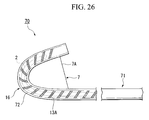
- FIG. 26 is an explanatory diagram showing a curved condition of the curvable catheter of the treatment tool inserting/withdrawing auxiliary device according to a sixth embodiment.
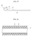
- FIG. 27 is a main part plan view showing the curvable catheter of the treatment tool inserting/withdrawing auxiliary device according to a seventh embodiment.
- FIG. 28 is a main part cross-sectional view showing the curvable catheter of the treatment tool inserting/withdrawing auxiliary device according to the seventh embodiment.
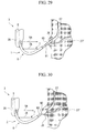
- FIG. 29 is an explanatory diagram showing a medical procedure through an endoscope by a modified example of the treatment tool inserting/withdrawing auxiliary device.
- FIG. 30 is an explanatory diagram showing the medical procedure through the endoscope by the modified example of the treatment tool inserting/withdrawing auxiliary device.
- FIG. 31 is a main part side view showing the curvable catheter of the modified example of the treatment tool inserting/withdrawing auxiliary device.
- FIG. 32 is a main part cross-sectional view showing the curvable catheter of the modified example of the treatment tool inserting/withdrawing auxiliary device.
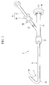
- a treatment tool inserting/withdrawing auxiliary device 1 includes: a curvable catheter (catheter) 6 having a through hole 6A through which a contrast medium injecting catheter (treatment tool for an endoscope, first treatment tool) 2 can be inserted, and which can be inserted into a channel 5 of a flexible endoscope 3; an operation wire 7 which is inserted into the curvable catheter 6, and is partially exposed to the outside of the curvable catheter 6 to form an exposed portion 7A supported on a distal end of the curvable catheter 6; an operation portion 8 which moves the operation wire 7 back and forth with respect to the curvable catheter 6; a treatment tool insertion/withdrawal port 10 which is provided in communication with the curvable catheter 6, and through which the contrast medium injecting catheter 2 can be inserted/withdrawn; and a branched portion 11 which is connected to a proximal end of the curvable catheter 6, and has the through hole 6A of the curvable catheter 6 branched into the operation portion 8 side and the treatment tool
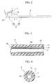
- the curvable catheter 6 includes: a first resin layer 12 serving as an innermost layer made from a fluororesin such as PTFE, PFA, FEP, and ETFE; a metal layer 13 arranged outside of the first resin layer 12; and a second resin layer 15 as the outermost layer arranged further outside of the metal layer 13.
- the metal layer 13 includes: a coil layer 13A made from a stainless steel or the like arranged on the distal side; and a mesh pipe 13B continually provided on the proximal end of the coil layer 13A.
- the element wire of the coil layer 13A and the element wire of the mesh pipe 13B are made from the same members.
- the element wires of the coil layer and the mesh pipe may be respectively made from separate members.
- the coil layer 13A is formed from a coiled a flat plate or round cross-section wire rod, and for example the flat plate has a width of 0.3mm and a thickness of 0.08mm, and the distance of a gap between the flat plate is 0.1mm to 0.5mm, and preferably 0.2mm and 0.3mm.
- the second resin layer 15 includes a relatively soft distal layer 15A arranged on the distal side of the curvable catheter 6; and a relatively hard proximal layer 15B arranged on the proximal side. As shown in FIG. 7, between the distal layer 15A and the proximal layer 15B may be arranged an intermediate layer 15C having a flexibility intermediate between them.
- the second resin layer 15 is made from a resin such as polyurethane and nylon, and is further separated into the abovementioned respective layers according to the difference in the hardness of the same resin.
- the distal layer 15A is arranged in a region including the exposed portion 7A. Moreover, the region arranged with the distal layer 15A becomes a curvable portion 16 which is curved by change of the length of the exposed portion 7A of the operation wire 7 according to the amount that the operation wire 7 is moved to the proximal side of the curvable catheter 6 by the operation portion 8.
- the portion arranged with the proximal layer 15B is more rigid than the distal side, and thus superior in the torque transmission property.
- the curvable portion 16 is curvable within a range between 0 to 170 degree of a curved angle, assuming that the curved angle is an angle defined by the axial centers of the proximal end and the distal end, and the curved angle becomes 0 when the axial centers of the proximal end and the distal end are approximately on the same line having the curvable portion 16 therebetween.
- the inner diameter of the curvable catheter 6 is 1.5mm to 5.7mm, preferably 2.0mm to 4.5mm, and more preferably 2.6mm to 3.3mm.
- the wall thickness of the curvable catheter 6 is 0.05mm to 0.5mm, and preferably 0.1mm to 0.4mm. This is based on an assumption that the contrast medium injecting catheter 2 having a minimum outer diameter of 1.3mm can be inserted therein and the curvable catheter 6 is inserted into the channel 5 of the endoscope 3 having an inner diameter of 6.0mm.
- the distal end of the operation wire 7 is connected to the vicinity of the distal end of the curvable catheter 6.
- the length L of the exposed portion 7A varies within a range more than 10mm but less than 40mm, depending on an angle ⁇ defined by the distal direction of the curvable catheter 6 and the proximal direction of the curvable catheter 6 by curving the curvable portion 16.
- the operation portion 8 includes an operation portion mainbody 17 which is detachably connected to the branched portion 11 and extended in the axial direction, and a slider 18 which is connected with the proximal end of the operation wire 7 and is relatively movable with respect to the operation portion mainbody 17.
- the travel distance of the slider 18 with respect to the operation portion mainbody 17 has a sufficient length for the angle ⁇ to be changed from 10 degrees to 90 degrees.
- the operation portion 8 is provided with a ratchet mechanism (not shown), enabling to move the slider 18 only to the proximal side of the operation portion mainbody 17. By pressing a release button 20 provided on the slider 18, the slider 18 can be also moved to the distal side of the operation portion mainbody 17.
- the branched portion 11 includes a first connector 21 which is detachably connected to the proximal end of the curvable catheter 6, and a second connector 22 which is detachably connected to the operation portion mainbody 17. Moreover, as shown in FIG. 9, the branched portion 11 is provided with: a first through hole 23 which is communicated with the through hole 6A, and is inserted with the operation wire 7 arranged in the curvable catheter 6; and a second through hole 25 which is communicated with the through hole 6A, and inserted with an endoscope treatment tool such as the contrast medium injecting catheter 2, branched in the middle. As shown in FIG. 10, a first through hole 23A and a second through hole 25A may be respectively and separately extended to the distal end of the curvable catheter.
- the description is regarding a manipulation such as inserting the contrast medium injecting catheter 2 into a duodenal papilla 26 using the endoscope 3, injecting a contrast medium into a bile duct 27 to diagnose under X-ray fluoroscopy, and removing all bile duct calculi.
- a manipulation regarding the pancreatic duct 27' in principle, the bile duct 27 is replaced with a pancreatic duct 27' in the following description.
- the insertion portion 28 of the endoscope 3 is inserted into the mouth of a patient (not shown), and the distal end of the insertion portion 28 is positioned in the vicinity of the duodenal papilla 26 through the esophagus (not shown). Then, by performing an angling operation or twisting operation of the endoscope 3, the line of sight 5A is adjusted so that the duodenal papilla 26 can be kept within the endoscope image.
- the abovementioned curvable catheter 6 of the treatment tool inserting/withdrawing auxiliary device 1 is inserted from the forcep port (not shown) of the endoscope 3 into the channel 5, and made to project from the channel 5. At this time, the slider 18 is moved with respect to the operation portion mainbody 17 so that the curvable catheter 6 smoothly projects.
- the operator grasps and moves the slider 18 of the operation portion 8 backward with respect to the operation portion mainbody 17 while observing the distal end of the curvable catheter 6 in an observation image.
- the length of the exposed portion 7A is shortened according to the pulled amount thereof.
- the curvable portion 16 is curved and the distal end of the curvable catheter 6 is moved to the proximal direction of the curvable catheter 6.
- the slider 18 When the slider 18 is moved to a predetermined position with respect to the operation portion mainbody 17, the slider 18 is fixed by the ratchet mechanism (not shown), and the curved angle of the curvable portion 16 is fixed in a condition where it is curved at a predetermined angle within a range between 90 degrees to 170 degrees that is suitable for inserting into the papilla. Furthermore, the operator grasps the branched portion 11 and rotates the curvable catheter 6 with respect to the channel 5, so as to match the distal direction of the curvable catheter 6 with the direction of the bile duct 27 as shown in FIG. 11. The operation of the slider 18 of the operation portion 8, and the rotation operation and the forward moving operation of the curvable catheter 6 may be performed not only by the operator but also by an assistant.
- the contrast medium injecting catheter 2 is inserted from the treatment tool insertion/withdrawal port 10 through the second through hole 25 into the through hole 6A of the curvable catheter 6.
- the contrast medium injecting catheter 2 may be previously inserted into the curvable catheter 6.
- the contrast medium injecting catheter 2 is made to project from the distal end of the curvable catheter 6, and inserted to a predetermined position in the bile duct 27. Then, the contrast medium is poured into the contrast medium injecting catheter 2, and the inside of the bile duct 27 is visually observed by means of X-ray contrast radiography.
- the release button 20 is pushed to bring the slider 18 into a slidable condition with respect to the operation portion mainbody 17, and the curvable catheter 6 is pushed out from the channel 5.
- the distal end of the curvable catheter 6 is inserted from the duodenal papilla 26 into the bile duct 27.
- the contrast medium injecting catheter 2 is withdrawn from the treatment tool insertion/withdrawal port 10 of the curvable catheter 6.
- the treatment tool insertion/withdrawal port 10 of the curvable catheter 6 is inserted with another treatment tool for an endoscope (second treatment tool) 29 such as a balloon, instead.
- second treatment tool 29 such as a balloon
- the treatment tool for an endoscope 29 is made to project from the curvable catheter 6 into the bile duct 27, to perform a predetermined treatment on the target site. If another treatment is to be further performed, the treatment tool for an endoscope 29 is withdrawn and another treatment tool for an endoscope (not shown) is inserted.
- the distal direction of the curvable catheter 6 projecting from the channel 5, by curving the curvable portion 16 of the curvable catheter 6, may be brought closer to the curvable catheter 6 by a predetermined angle, such as a direction of 10 degree, with respect to the proximal direction of the curvable catheter 6 in the channel 5. Therefore, while the observation image by the endoscope 3 is fixed, the distal direction of the curvable catheter 6 can be matched with the direction of the bile duct 27 by merely curving the curvable portion 16 of the curvable catheter 6. As a result, without requiring a high skill for positioning, cannulation can be readily performed in a condition where the distal end of the endoscope insertion portion 28 is fixed with respect to the duodenal papilla 26.
- the treatment tool is not directly inserted into the channel 5, but inserted into the curvable catheter 6 which has been previously inserted therein. Therefore, for exchanging the treatment tool, the curvable catheter 6 can be used as a guide, and the treatment tool can be readily exchanged without requiring the guide wire.
- the distal side of the second resin layer 15 of the curvable catheter 6 is a soft distal layer 15A, and the curvable portion 16 is arranged with the coil layer 13A. Therefore, when the curvable portion 16 is curved, a large curved amount can be obtained without buckling the curvable catheter 6.
- the proximal side of the second resin layer 15 is a hard proximal layer 15B, and is arranged with the mesh pipe 13B. Therefore, while maintaining a predetermined rigidity, insertion/withdrawal into/from the channel 5 can be readily performed, and the rotation torque when rotated with respect to the channel 5 can be suitably transferred to the distal side.
- the first resin layer 12 serving as the innermost layer of the curvable catheter 6 contains a fluororesin. Therefore the frictional force can be reduced, and the contrast medium injecting catheter 2 and another endoscope treatment tool inserted into the through hole 6A can be smoothly inserted/withdrawn.
- the first resin layer may contain a hydrophilic resin.
- the effect of the treatment tool inserting/withdrawing auxiliary device 1 was described.
- another treatment tool for an endoscope 29 such as a balloon may be inserted instead of the contrast medium injecting catheter 2 at the beginning.
- a second embodiment of the present invention is described with reference to the drawings.
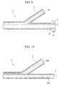
- the difference between the second embodiment and the first embodiment is the point that, as shown in FIG. 16, a treatment tool inserting/withdrawing auxiliary device 30 according to the present embodiment has a pitch L1 on the proximal side of the coil layer 31 greater than a pitch L2 on the distal side thereof.
- the pitch L2 in the vicinity of the curvable portion 16 has the same interval as that of the coil layer 13A according to the first embodiment.
- the pitch L1 in the connection part with the mesh pipe 13B is 0.5mm to 0.6mm, and the pitch in the middle is changed so that the pitch gradually becomes greater from the distal side to the proximal side.
- this treatment tool inserting/withdrawing auxiliary device 30 and medical procedure through an endoscope a similar effect to that of the first embodiment can be demonstrated. Moreover, by using this device, a similar medical procedure can be performed.
- the pitch of the coil layer 31 is small on the distal side in the vicinity of the curvable portion 16, the curvable portion 16 can be curved without buckling.
- the pitch is gradually changed, in the connection part between the coil layer 31 and the mesh pipe 13B, discontinuous change with respect to the curve rigidity can be made less than that of the first embodiment, and the buckling resistance can be improved.
- a third embodiment of the present invention is described with reference to the drawings.
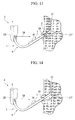
- the difference between the third embodiment and the first embodiment is the point that, as shown in FIG. 17 and FIG. 18, the distal end of a curvable catheter 41 of a treatment tool inserting/withdrawing auxiliary device 40 according to the present embodiment is provided with visual check markers 42 for identifying the length from the distal end.
- the visual check markers 42 include for example: a reference visual check marker 42X provided at the most distal end of the curvable catheter 41; a first position 42A provided in a position 10mm from the distal end of the curvable catheter 41; a second position 42B provided in a position 20mm therefrom; a third position 42C provided in a position 30mm therefrom; and a fourth position 42D provided in a position 40mm therefrom.
- the respective positions may be provided by an X-ray impermeable material so as to be observable under X-ray contrast radiography.
- the number of the provided markers and the distance from the distal end of the curvable catheter 41 are not limited to the above, and may be provided according to the manipulation.
- the visual check markers 42 are provided, it can be ascertained in an X-ray image under X-ray contrast radiography how far the distal side of the curvable catheter 41 is inserted into the bile duct and the like. Moreover, even if not under X-ray contrast radiography, the visual check markers 42 can be confirmed by an endoscopic image.
- a fourth embodiment of the present invention is described with reference to the drawings.
- the difference between the fourth embodiment and the first embodiment is the point that, as shown in FIG. 19, an operation wire 51 of a treatment tool inserting/withdrawing auxiliary device 50 according to the present embodiment has one end 51a connected to the operation portion mainbody 17 of the operation portion 8, and the other end 51b side folded at the distal end of the curvable catheter 6 and arranged toward the proximal side.
- a treatment tool insertion/withdrawal port 52 of the branched portion 11 is detachably connected an extension portion 56 that is provided with a new treatment tool insertion port 55 and a wire insertion/withdrawal port 53 through which the other end 51b side of the operation wire 51 is inserted, via a connector 57. While the extension portion 56 is connected, the second through hole 25 of the branched portion 11, the wire insertion/withdrawal port 53, and the new treatment tool insertion/withdrawal port 55 are communicated.
- the operation wire 51 projecting from the wire insertion/withdrawal port 53 is arranged with a clasp 58 for preventing the operation wire 51 from being pulled into the wire insertion/withdrawal port 53.
- This clasp 58 is formed larger than the inner diameter of the wire insertion/withdrawal port 53, and detachably attached to the operation wire 51.
- the curvable catheter 6 of the treatment tool inserting/withdrawing auxiliary device 50 is made to project from the distal opening of the channel of an endoscope (not shown).
- an operator performs a similar operation to that of the first embodiment while observing an observation image.
- the contrast medium injecting catheter (not shown) is inserted into the bile duct. Then, the contrast medium is poured into the contrast medium injecting catheter, and the inside of the bile duct is visually observed by means of X-ray contrast radiography.
- the clasp 58 is taken off from the operation wire 51, and further the connector 22 is separated to take out the operation portion 8 from the curvable catheter 6.
- the other end 51b side of the operation wire 51 is moved to the distal direction in the curvable catheter 6, is folded at the distal end, and goes again toward the proximal side, to be pulled out from the curvable catheter 6 together with the operation portion 8.
- the curvable catheter 6 is inserted into the bile duct, and after withdrawing the operation wire 51 and the operation portion 8, the contrast medium injecting catheter 2 is withdrawn from the treatment tool insertion/withdrawal port 55 of the curvable catheter 6.
- the treatment tool insertion/withdrawal port 55 of the curvable catheter 6 is inserted with another treatment tool for an endoscope such as a balloon (not shown), instead, to perform a predetermined treatment on the target site.
- the operation wire 51 can be withdrawn from the curvable catheter 6 after the contrast medium injecting catheter is inserted into the bile duct. Therefore, when the endoscope treatment tool is inserted into the curvable catheter 6, the treatment tool can be more readily exchanged without being interfered with by the operation wire 51.
- a fifth embodiment of the present invention is described with reference to the drawings.
- the difference between the fifth embodiment and the first embodiment is the point that, as shown in FIG. 20, the distal outer face of a curvable catheter 61 of a treatment tool inserting/withdrawing auxiliary device 60 according to the present embodiment is provided with an index 62 formed to be gradually wider toward the proximal side.
- the index 62 is formed in an approximate isosceles triangle, and is arranged in a predetermined position on the distal side from the exposed portion 7A of the operation wire 7, so that the apex of the isosceles faces to the distal side of the curvable catheter 61.
- the shape of the index 62 is not limited to an approximate isosceles triangle. As shown in FIG. 21, there may be an index 63 where a plurality of only the isosceles portions of isosceles triangles are arranged in a row in the longitudinal direction of the curvable catheter 61.
- the distal end of the insertion portion of an endoscope (not shown) is positioned in the vicinity of the duodenal papilla 26, to capture the duodenal papilla 26 in the endoscope image.
- the curvable catheter 61 of the treatment tool inserting/withdrawing auxiliary device 60 is inserted into the channel, so as to project from the distal opening of the channel.
- An operator (not shown) performs a similar operation to that of the first embodiment while observing an observation image V by means of the endoscope, to curve the curvable portion 16 at a predetermined angle, so that the distal end of the curvable catheter 61 faces toward the proximal direction of the curvable catheter 61.
- the index 62 appears in a nearly original form of the approximate isosceles triangle in the observation image as shown in FIG. 23.
- the index 62 appears in a squashed form in the height direction in the observation image as shown in FIG. 25.
- the distal end of the curvable catheter 61 faces the direction of 11 o'clock with respect to the duodenal papilla 26.
- the distal end of the curvable catheter 61 faces the direction of 4 o'clock with respect to the duodenal papilla 26. Therefore, the shape of the index 62 is observed to judge from the shape in the image whether or not the distal direction of the curvable catheter 61 is matched with the direction of the bile duct 27 or the pancreatic duct 27'. Then the contrast medium injecting catheter that has been inserted into the curvable catheter 61 is pushed out, and the distal end of the contrast medium injecting catheter is inserted from the duodenal papilla 26 into the bile duct 27.
- the shape of the index 62 in the observation image appears differently according to the curved angle of the distal end of the curvable catheter 61 with respect to the insertion portion 28. Therefore, the operator can readily judge whether or not the distal end of the curvable catheter 61 faces toward a predetermined direction by visually checking the shape of the index 62 in the observation image.
- a sixth embodiment of the present invention is described with reference to the drawings.
- the difference between the sixth embodiment and the first embodiment is the point that, as shown in FIG. 26, a first resin layer (not shown) and a second resin layer 72 in the region including the curvable portion 16 of a curvable catheter 71 of a treatment tool inserting/withdrawing auxiliary device 70 according to the present embodiment are made from a transparent resin.
- the first resin layer and the second resin layer 72 are respectively made from resins such as nylon, urethane, PTFE, and PFA.
- a treatment tool passing through the inside can be visually checked in an observation image of the endoscope, and the position of the treatment tool with respect to the curvable catheter 71 can be readily determined.
- a seventh embodiment of the present invention is described with reference to the drawings.
- the difference between the seventh embodiment and the first embodiment is the point that the surface of the proximal side of a curvable catheter 81 of a treatment tool inserting/withdrawing auxiliary device 80 according to the present embodiment is provided with convex portions 82.
- the convex portions 82 are minute and are formed on the second resin layer 83 on the proximal side from the curvable portion 16 as shown in FIG. 27 and FIG. 28.
- the convex portions 82 may be provided not only on the proximal side of the curvable catheter, but also to the distal end. Moreover, concavities may be provided instead of the convex portions 82.
- the surface of the curvable catheter 81 is provided with the convex portions 82, when the curvable catheter 81 is inserted into a channel (not shown), the frictional force with the wall surface of the channel can be reduced and the curvable catheter 81 can be readily inserted/withdrawn.
- the surface of at least the proximal side of the curvable catheter 81 may be a hydrophilic lubricant surface.
- a contrast medium injecting catheter 91 provided with an incision knife 90 connected to a high frequency power source (not shown) on the distal end as shown in FIG. 29, or a contrast medium injecting catheter 93 provided with a balloon 92 as shown in FIG. 30.
- the contrast medium is poured into the contrast medium injecting catheter 91 or 93, and the inside of the bile duct 27 is visually observed by means of X-ray contrast radiography. Then, without withdrawing the contrast medium injecting catheter 91 or 93 from the treatment tool insertion/withdrawal port (not shown) of the curvable catheter 6, the sphincter of the duodenal papilla 26 can be incised as it is by the incision knife 90, or the sphincter of the duodenal papilla 26 can be extended by the balloon 92.
- the distal end thereof may be fixed to a fixing portion 95C provided in the vicinity of the distal end of the curvable catheter 95 (about 0.5mm to 5.0mm from the distal end).
- the reason for being in the vicinity of the distal end is that the distal end of the curvable catheter is tapered.
- the curvable catheter 95 can also be curved.
Landscapes
- Health & Medical Sciences (AREA)
- Life Sciences & Earth Sciences (AREA)
- Engineering & Computer Science (AREA)
- Heart & Thoracic Surgery (AREA)
- Animal Behavior & Ethology (AREA)
- Pulmonology (AREA)
- Anesthesiology (AREA)
- Biomedical Technology (AREA)
- Veterinary Medicine (AREA)
- Hematology (AREA)
- Biophysics (AREA)
- General Health & Medical Sciences (AREA)
- Public Health (AREA)
- Mechanical Engineering (AREA)
- Media Introduction/Drainage Providing Device (AREA)
- Endoscopes (AREA)
- Surgical Instruments (AREA)
Abstract
Description
- The present invention relates to a treatment tool inserting/withdrawing auxiliary device.
- For performing cannulation (selective insertion into a pancreatic duct/bile duct) in diagnosis and treatment of a pancreatic/bile duct system, while a treatment tool such as a contrast medium injecting catheter is inserted into a channel of a flexible endoscope, back-and-forth moving operation, angling operation, and twisting operation of the endoscope insertion portion, raising-up operation of a forcep stage arranged on the distal end of the insertion portion, and back-and-forth moving operation of the contrast medium injecting catheter with respect to the channel are performed in combination. In this case, it is necessary to match the axial directions of the distal end of the contrast medium injecting catheter and the bile duct (or the pancreatic duct) by delicate operations of the endoscope and the contrast medium injecting catheter.
- Therefore, a contrast medium injecting catheter for facilitating these operations is disclosed in
Japanese Unexamined Patent Application, First Publication No. 2002-272675 No. 2004-532668 U.S. Patent No. 6,659,981 . - According to these, since the distal end of the catheter is curved to some extent, the positioning operation by the endoscope insertion portion can be assisted.
- On the other hand, after the cannulation, in order to exchange the contrast medium injecting catheter and a treatment tool required for the subsequent treatment, a guide wire having at least twice the length of the contrast medium injecting catheter is inserted into the contrast medium injecting catheter, and the contrast medium injecting catheter is withdrawn from the endoscope through the guide wire. Then, the treatment tool to be used is inserted into the endoscope along the guide wire, and moved to the target site.
- However, because the operation of bringing the endoscope to a position where cannulation can be readily performed cannot be perceptively performed, the distal end of the catheter must be positioned by a skilled manoeuvering of the endoscope even though the distal end of the catheter is curved to some extent. As a result, a high skill for positioning is required for the operator.
- Moreover, when plural treatment tools are used, the treatment tools must be inserted and withdrawn using a guide wire; therefore, the exchanging operation between the treatment tools is complicated, and makes the operation time longer.
- An object of the present invention is to provide a device capable of readily performing cannulation while the distal end of an endoscope insertion portion is positioned with respect to the duodenal papilla, and capable of exchanging treatment tools without using a guide wire.
- A treatment tool inserting/withdrawing auxiliary device according to a first aspect of the present invention includes: a catheter through which a treatment tool for an endoscope is to be inserted, and which is insertable into a channel of a flexible endoscope; an operation wire which is inserted into the catheter, and is supported on a distal end or the vicinity of the catheter; an operation portion which moves the operation wire back and forth with respect to the catheter; and a curvable portion which is provided on the catheter and is curved by a back and forth movement of the operation wire, wherein the curvable portion is curvable within a range between 0 to 170 degree of a curved angle, assuming that the curved angle is an angle defined by axial centers of the proximal end and the distal end of the curvable portion, and the curved angle becomes 0 when the axial centers of the proximal end and the distal end are approximately on the same line having the curvable portion therebetween.
- A second aspect of the present invention is the treatment tool inserting/withdrawing auxiliary device according to the first aspect of the present invention, wherein the operation wire is partially exposed to the outside of the catheter to form an exposed portion, a length of the exposed portion varies according to a moved amount of the operation wire to the proximal side of the catheter by the operation portion, and the curvable portion is curved according to the length of the exposed portion.
- A third aspect of the present invention is the treatment tool inserting/withdrawing auxiliary device according to the first aspect of the present invention, wherein a coil layer is arranged at least on the curvable portion of the catheter.
- A fourth aspect of the present invention is the treatment tool inserting/withdrawing auxiliary device according to the third aspect of the present invention, wherein a mesh pipe layer is continually provided on the proximal end of the coil layer, and arranged on the catheter.
- A fifth aspect of the present invention is the treatment tool inserting/withdrawing auxiliary device according to the third aspect of the present invention, wherein a fluororesin layer is arranged at least on the inside of the coil layer of the catheter.
- A sixth aspect of the present invention is the treatment tool inserting/withdrawing auxiliary device according to the third aspect of the present invention, wherein a pitch on the proximal side of the coil layer is greater than a pitch of the distal side thereof.
- A seventh aspect of the present invention is the treatment tool inserting/withdrawing auxiliary device according to the first aspect of the present invention, wherein a visual check marker for identifying a length from the distal end is provided on the distal end of the catheter.
- An eighth aspect of the present invention is the treatment tool inserting/withdrawing auxiliary device according to the first aspect of the present invention, further including a treatment tool insertion/withdrawal port which is provided in communication with the catheter, and through which the treatment tool for an endoscope is to be inserted/withdrawn.
- A ninth aspect of the present invention is the treatment tool inserting/withdrawing auxiliary device according to the eighth aspect of the present invention, wherein one end of the operation wire is connected to the operation portion, and the other end side is folded on the distal end of the catheter and arranged toward the proximal side of the catheter.
- A tenth aspect of the present invention is the treatment tool inserting/withdrawing auxiliary device according to the ninth aspect of the present invention, wherein the operation portion is detachably connected to the catheter.
- An eleventh aspect of the present invention is the treatment tool inserting/withdrawing auxiliary device according to the first aspect of the present invention, wherein a length of the exposed portion varies within a range of more than 10mm and less than 40mm, by a back-and-forth moving operation of the operation portion.
- A twelfth aspect of the present invention is the treatment tool inserting/withdrawing auxiliary device according to the first aspect of the present invention, wherein the distal end of the catheter is provided with an index at least a part of which is formed to be gradually wider toward the proximal side.
- A thirteenth aspect of the present invention is the treatment tool inserting/withdrawing auxiliary device according to the first aspect of the present invention, wherein at least the curvable portion of the catheter comprises a transparent resin.
- A fourteenth aspect of the present invention is the treatment tool inserting/withdrawing auxiliary device according to the first aspect of the present invention, wherein a surface of the proximal side of the catheter is provided with convex portions or concavities.
- According to the present invention, because the distal end of the catheter projecting from the channel of the endoscope can be brought close to the proximal portion of the curvable catheter so that the direction of the distal end of the catheter and the direction of the proximal portion define a predetermined angle, the direction of the distal end of the catheter can be matched with the direction of insertion by merely curving the curvable portion of the curvable catheter. Accordingly, without requiring a high skill for positioning, cannulation can be readily performed in a condition where the distal end of the endoscope insertion portion is fixed.
- FIG. 1 is an overall schematic diagram showing a treatment tool inserting/withdrawing auxiliary device according to a first embodiment.
- FIG. 2 is a main part side view showing a curvable catheter of the treatment tool inserting/withdrawing auxiliary device according to the first embodiment.
- FIG. 3 is a cross-sectional view taken along the line A-A' in FIG. 2.
- FIG. 4 is a cross-sectional view taken along the line B-B' in FIG. 2.
- FIG. 5 is an internal configuration diagram of the main part showing the curvable catheter of the treatment tool inserting/withdrawing auxiliary device according to the first embodiment.
- FIG. 6 is an internal configuration diagram of the main part showing the curvable catheter of the treatment tool inserting/withdrawing auxiliary device according to the first embodiment.
- FIG. 7 is an internal configuration diagram of the main part showing a modified example of the curvable catheter of the treatment tool inserting/withdrawing auxiliary device according to the first embodiment.
- FIG. 8 is an explanatory diagram showing the curved condition of the curvable catheter of the treatment tool inserting/withdrawing auxiliary device according to the first embodiment.
- FIG. 9 is a cross-sectional view showing a branched portion of the treatment tool inserting/withdrawing auxiliary device according to the first embodiment.
- FIG. 10 is a cross-sectional view showing a modified example of the branched portion of the treatment tool inserting/withdrawing auxiliary device according to the first embodiment.
- FIG. 11 is an explanatory diagram showing a medical procedure through an endoscope by the treatment tool inserting/withdrawing auxiliary device according to the first embodiment.
- FIG. 12 is an explanatory diagram showing the medical procedure through the endoscope by the treatment tool inserting/withdrawing auxiliary device according to the first embodiment.
- FIG. 13 is an explanatory diagram showing the medical procedure through the endoscope by the treatment tool inserting/withdrawing auxiliary device according to the first embodiment.
- FIG. 14 is an explanatory diagram showing the medical procedure through the endoscope by the treatment tool inserting/withdrawing auxiliary device according to the first embodiment.
- FIG. 15 is an explanatory diagram showing the medical procedure through the endoscope by the treatment tool inserting/withdrawing auxiliary device according to the first embodiment.
- FIG. 16 is an internal configuration diagram of the main part showing the curvable catheter of the treatment tool inserting/withdrawing auxiliary device according to a second embodiment.
- FIG. 17 is an explanatory diagram showing a curved condition of the curvable catheter of the treatment tool inserting/withdrawing auxiliary device according to a third embodiment.
- FIG. 18 is a main part plan view showing the curvable catheter of the treatment tool inserting/withdrawing auxiliary device according to the third embodiment.
- FIG. 19 is an overall schematic diagram showing the treatment tool inserting/withdrawing auxiliary device according to a fourth embodiment.
- FIG. 20 is a main part plan view showing the curvable catheter of the treatment tool inserting/withdrawing auxiliary device according to a fifth embodiment.
- FIG. 21 is a main part plan view showing a modified example of the curvable catheter of the treatment tool inserting/withdrawing auxiliary device according to the fifth embodiment.
- FIG. 22 is an explanatory diagram showing a curved condition of the curvable catheter of the treatment tool inserting/withdrawing auxiliary device according to the fifth embodiment.
- FIG. 23 is an explanatory diagram showing a medical procedure through an endoscope by the treatment tool inserting/withdrawing auxiliary device according to the fifth embodiment.
- FIG. 24 is an explanatory diagram showing the curved condition of the treatment tool inserting/withdrawing auxiliary device according to the fifth embodiment.
- FIG. 25 is an explanatory diagram showing the medical procedure through the endoscope by the treatment tool inserting/withdrawing auxiliary device according to the fifth embodiment.
- FIG. 26 is an explanatory diagram showing a curved condition of the curvable catheter of the treatment tool inserting/withdrawing auxiliary device according to a sixth embodiment.
- FIG. 27 is a main part plan view showing the curvable catheter of the treatment tool inserting/withdrawing auxiliary device according to a seventh embodiment.
- FIG. 28 is a main part cross-sectional view showing the curvable catheter of the treatment tool inserting/withdrawing auxiliary device according to the seventh embodiment.
- FIG. 29 is an explanatory diagram showing a medical procedure through an endoscope by a modified example of the treatment tool inserting/withdrawing auxiliary device.
- FIG. 30 is an explanatory diagram showing the medical procedure through the endoscope by the modified example of the treatment tool inserting/withdrawing auxiliary device.
- FIG. 31 is a main part side view showing the curvable catheter of the modified example of the treatment tool inserting/withdrawing auxiliary device.
- FIG. 32 is a main part cross-sectional view showing the curvable catheter of the modified example of the treatment tool inserting/withdrawing auxiliary device.
- Hereunder is a detailed description of preferred embodiments according to the present invention. In the following description, the same reference symbols are used for the same components, and duplicate descriptions are omitted.
- A treatment tool inserting/withdrawing
auxiliary device 1 according to the present embodiment includes: a curvable catheter (catheter) 6 having a throughhole 6A through which a contrast medium injecting catheter (treatment tool for an endoscope, first treatment tool) 2 can be inserted, and which can be inserted into achannel 5 of aflexible endoscope 3; anoperation wire 7 which is inserted into thecurvable catheter 6, and is partially exposed to the outside of thecurvable catheter 6 to form an exposedportion 7A supported on a distal end of thecurvable catheter 6; anoperation portion 8 which moves theoperation wire 7 back and forth with respect to thecurvable catheter 6; a treatment tool insertion/withdrawal port 10 which is provided in communication with thecurvable catheter 6, and through which the contrastmedium injecting catheter 2 can be inserted/withdrawn; and a branchedportion 11 which is connected to a proximal end of thecurvable catheter 6, and has the throughhole 6A of thecurvable catheter 6 branched into theoperation portion 8 side and the treatment tool insertion/withdrawal port 10 side. - As shown in FIG. 2 to FIG. 6, the
curvable catheter 6 includes: afirst resin layer 12 serving as an innermost layer made from a fluororesin such as PTFE, PFA, FEP, and ETFE; ametal layer 13 arranged outside of thefirst resin layer 12; and asecond resin layer 15 as the outermost layer arranged further outside of themetal layer 13. Themetal layer 13 includes: acoil layer 13A made from a stainless steel or the like arranged on the distal side; and amesh pipe 13B continually provided on the proximal end of thecoil layer 13A. The element wire of thecoil layer 13A and the element wire of themesh pipe 13B are made from the same members. The element wires of the coil layer and the mesh pipe may be respectively made from separate members. Thecoil layer 13A is formed from a coiled a flat plate or round cross-section wire rod, and for example the flat plate has a width of 0.3mm and a thickness of 0.08mm, and the distance of a gap between the flat plate is 0.1mm to 0.5mm, and preferably 0.2mm and 0.3mm. - The
second resin layer 15 includes a relatively softdistal layer 15A arranged on the distal side of thecurvable catheter 6; and a relatively hardproximal layer 15B arranged on the proximal side. As shown in FIG. 7, between thedistal layer 15A and theproximal layer 15B may be arranged anintermediate layer 15C having a flexibility intermediate between them. Thesecond resin layer 15 is made from a resin such as polyurethane and nylon, and is further separated into the abovementioned respective layers according to the difference in the hardness of the same resin. - The
distal layer 15A is arranged in a region including the exposedportion 7A. Moreover, the region arranged with thedistal layer 15A becomes acurvable portion 16 which is curved by change of the length of the exposedportion 7A of theoperation wire 7 according to the amount that theoperation wire 7 is moved to the proximal side of thecurvable catheter 6 by theoperation portion 8. The portion arranged with theproximal layer 15B is more rigid than the distal side, and thus superior in the torque transmission property. Thecurvable portion 16 is curvable within a range between 0 to 170 degree of a curved angle, assuming that the curved angle is an angle defined by the axial centers of the proximal end and the distal end, and the curved angle becomes 0 when the axial centers of the proximal end and the distal end are approximately on the same line having thecurvable portion 16 therebetween. - The inner diameter of the
curvable catheter 6 is 1.5mm to 5.7mm, preferably 2.0mm to 4.5mm, and more preferably 2.6mm to 3.3mm. Moreover, the wall thickness of thecurvable catheter 6 is 0.05mm to 0.5mm, and preferably 0.1mm to 0.4mm. This is based on an assumption that the contrastmedium injecting catheter 2 having a minimum outer diameter of 1.3mm can be inserted therein and thecurvable catheter 6 is inserted into thechannel 5 of theendoscope 3 having an inner diameter of 6.0mm. - As shown in FIG. 8, the distal end of the
operation wire 7 is connected to the vicinity of the distal end of thecurvable catheter 6. The length L of the exposedportion 7A varies within a range more than 10mm but less than 40mm, depending on an angle θ defined by the distal direction of thecurvable catheter 6 and the proximal direction of thecurvable catheter 6 by curving thecurvable portion 16. - The
operation portion 8 includes anoperation portion mainbody 17 which is detachably connected to the branchedportion 11 and extended in the axial direction, and aslider 18 which is connected with the proximal end of theoperation wire 7 and is relatively movable with respect to theoperation portion mainbody 17. The travel distance of theslider 18 with respect to theoperation portion mainbody 17 has a sufficient length for the angle θ to be changed from 10 degrees to 90 degrees. - The
operation portion 8 is provided with a ratchet mechanism (not shown), enabling to move theslider 18 only to the proximal side of theoperation portion mainbody 17. By pressing arelease button 20 provided on theslider 18, theslider 18 can be also moved to the distal side of theoperation portion mainbody 17. - The branched
portion 11 includes afirst connector 21 which is detachably connected to the proximal end of thecurvable catheter 6, and asecond connector 22 which is detachably connected to theoperation portion mainbody 17. Moreover, as shown in FIG. 9, the branchedportion 11 is provided with: a first throughhole 23 which is communicated with the throughhole 6A, and is inserted with theoperation wire 7 arranged in thecurvable catheter 6; and a second throughhole 25 which is communicated with the throughhole 6A, and inserted with an endoscope treatment tool such as the contrastmedium injecting catheter 2, branched in the middle. As shown in FIG. 10, a first throughhole 23A and a second throughhole 25A may be respectively and separately extended to the distal end of the curvable catheter. - Next is a description of the effect of the treatment tool inserting/withdrawing
auxiliary device 1 according to the present embodiment, together with a medical procedure through an endoscope using this. As the following medical procedure, the description is regarding a manipulation such as inserting the contrastmedium injecting catheter 2 into aduodenal papilla 26 using theendoscope 3, injecting a contrast medium into abile duct 27 to diagnose under X-ray fluoroscopy, and removing all bile duct calculi. For a manipulation regarding the pancreatic duct 27', in principle, thebile duct 27 is replaced with a pancreatic duct 27' in the following description. - Firstly, the
insertion portion 28 of theendoscope 3 is inserted into the mouth of a patient (not shown), and the distal end of theinsertion portion 28 is positioned in the vicinity of theduodenal papilla 26 through the esophagus (not shown). Then, by performing an angling operation or twisting operation of theendoscope 3, the line ofsight 5A is adjusted so that theduodenal papilla 26 can be kept within the endoscope image. Next, theabovementioned curvable catheter 6 of the treatment tool inserting/withdrawingauxiliary device 1 is inserted from the forcep port (not shown) of theendoscope 3 into thechannel 5, and made to project from thechannel 5. At this time, theslider 18 is moved with respect to theoperation portion mainbody 17 so that thecurvable catheter 6 smoothly projects. - Next, the operator (not shown) grasps and moves the
slider 18 of theoperation portion 8 backward with respect to theoperation portion mainbody 17 while observing the distal end of thecurvable catheter 6 in an observation image. At this time, since the proximal side of theoperation wire 7 is moved to the proximal side with respect to thecurvable catheter 6, the length of the exposedportion 7A is shortened according to the pulled amount thereof. According to the length of this exposedportion 7A, thecurvable portion 16 is curved and the distal end of thecurvable catheter 6 is moved to the proximal direction of thecurvable catheter 6. - When the
slider 18 is moved to a predetermined position with respect to theoperation portion mainbody 17, theslider 18 is fixed by the ratchet mechanism (not shown), and the curved angle of thecurvable portion 16 is fixed in a condition where it is curved at a predetermined angle within a range between 90 degrees to 170 degrees that is suitable for inserting into the papilla. Furthermore, the operator grasps the branchedportion 11 and rotates thecurvable catheter 6 with respect to thechannel 5, so as to match the distal direction of thecurvable catheter 6 with the direction of thebile duct 27 as shown in FIG. 11. The operation of theslider 18 of theoperation portion 8, and the rotation operation and the forward moving operation of thecurvable catheter 6 may be performed not only by the operator but also by an assistant. - After the
curvable catheter 6 is positioned, the contrastmedium injecting catheter 2 is inserted from the treatment tool insertion/withdrawal port 10 through the second throughhole 25 into the throughhole 6A of thecurvable catheter 6. The contrastmedium injecting catheter 2 may be previously inserted into thecurvable catheter 6. Moreover, as shown in FIG. 12, the contrastmedium injecting catheter 2 is made to project from the distal end of thecurvable catheter 6, and inserted to a predetermined position in thebile duct 27. Then, the contrast medium is poured into the contrastmedium injecting catheter 2, and the inside of thebile duct 27 is visually observed by means of X-ray contrast radiography. - In this condition, the
release button 20 is pushed to bring theslider 18 into a slidable condition with respect to theoperation portion mainbody 17, and thecurvable catheter 6 is pushed out from thechannel 5. At this time, while canceling the curved condition of thecurvable portion 16, as shown in FIG. 13, the distal end of thecurvable catheter 6 is inserted from theduodenal papilla 26 into thebile duct 27. - Moreover, in a condition where the position of the
insertion portion 28 of theendoscope 3 and the position of thecurvable catheter 6 are fixed, as shown in FIG. 14, the contrastmedium injecting catheter 2 is withdrawn from the treatment tool insertion/withdrawal port 10 of thecurvable catheter 6. - After the withdrawal, the treatment tool insertion/
withdrawal port 10 of thecurvable catheter 6 is inserted with another treatment tool for an endoscope (second treatment tool) 29 such as a balloon, instead. As shown in FIG. 15, the treatment tool for anendoscope 29 is made to project from thecurvable catheter 6 into thebile duct 27, to perform a predetermined treatment on the target site. If another treatment is to be further performed, the treatment tool for anendoscope 29 is withdrawn and another treatment tool for an endoscope (not shown) is inserted. - According to this treatment tool inserting/withdrawing
auxiliary device 1 and medical procedure through an endoscope, the distal direction of thecurvable catheter 6 projecting from thechannel 5, by curving thecurvable portion 16 of thecurvable catheter 6, may be brought closer to thecurvable catheter 6 by a predetermined angle, such as a direction of 10 degree, with respect to the proximal direction of thecurvable catheter 6 in thechannel 5. Therefore, while the observation image by theendoscope 3 is fixed, the distal direction of thecurvable catheter 6 can be matched with the direction of thebile duct 27 by merely curving thecurvable portion 16 of thecurvable catheter 6. As a result, without requiring a high skill for positioning, cannulation can be readily performed in a condition where the distal end of theendoscope insertion portion 28 is fixed with respect to theduodenal papilla 26. - Moreover, the treatment tool is not directly inserted into the
channel 5, but inserted into thecurvable catheter 6 which has been previously inserted therein. Therefore, for exchanging the treatment tool, thecurvable catheter 6 can be used as a guide, and the treatment tool can be readily exchanged without requiring the guide wire. - Furthermore, the distal side of the
second resin layer 15 of thecurvable catheter 6 is a softdistal layer 15A, and thecurvable portion 16 is arranged with thecoil layer 13A. Therefore, when thecurvable portion 16 is curved, a large curved amount can be obtained without buckling thecurvable catheter 6. On the other hand, the proximal side of thesecond resin layer 15 is a hardproximal layer 15B, and is arranged with themesh pipe 13B. Therefore, while maintaining a predetermined rigidity, insertion/withdrawal into/from thechannel 5 can be readily performed, and the rotation torque when rotated with respect to thechannel 5 can be suitably transferred to the distal side. - Moreover, the
first resin layer 12 serving as the innermost layer of thecurvable catheter 6 contains a fluororesin. Therefore the frictional force can be reduced, and the contrastmedium injecting catheter 2 and another endoscope treatment tool inserted into the throughhole 6A can be smoothly inserted/withdrawn. The first resin layer may contain a hydrophilic resin. - Moreover, in the example of inserting the contrast
medium injecting catheter 2, the effect of the treatment tool inserting/withdrawingauxiliary device 1 was described. However, another treatment tool for anendoscope 29 such as a balloon may be inserted instead of the contrastmedium injecting catheter 2 at the beginning. - A second embodiment of the present invention is described with reference to the drawings. The difference between the second embodiment and the first embodiment is the point that, as shown in FIG. 16, a treatment tool inserting/withdrawing
auxiliary device 30 according to the present embodiment has a pitch L1 on the proximal side of thecoil layer 31 greater than a pitch L2 on the distal side thereof. - The pitch L2 in the vicinity of the
curvable portion 16 has the same interval as that of thecoil layer 13A according to the first embodiment. The pitch L1 in the connection part with themesh pipe 13B is 0.5mm to 0.6mm, and the pitch in the middle is changed so that the pitch gradually becomes greater from the distal side to the proximal side. - According to this treatment tool inserting/withdrawing
auxiliary device 30 and medical procedure through an endoscope, a similar effect to that of the first embodiment can be demonstrated. Moreover, by using this device, a similar medical procedure can be performed. In particular, since the pitch of thecoil layer 31 is small on the distal side in the vicinity of thecurvable portion 16, thecurvable portion 16 can be curved without buckling. Moreover, since the pitch is gradually changed, in the connection part between thecoil layer 31 and themesh pipe 13B, discontinuous change with respect to the curve rigidity can be made less than that of the first embodiment, and the buckling resistance can be improved. - A third embodiment of the present invention is described with reference to the drawings. The difference between the third embodiment and the first embodiment is the point that, as shown in FIG. 17 and FIG. 18, the distal end of a
curvable catheter 41 of a treatment tool inserting/withdrawingauxiliary device 40 according to the present embodiment is provided withvisual check markers 42 for identifying the length from the distal end. - The
visual check markers 42 include for example: a reference visual check marker 42X provided at the most distal end of thecurvable catheter 41; afirst position 42A provided in a position 10mm from the distal end of thecurvable catheter 41; asecond position 42B provided in a position 20mm therefrom; athird position 42C provided in a position 30mm therefrom; and afourth position 42D provided in a position 40mm therefrom. The respective positions may be provided by an X-ray impermeable material so as to be observable under X-ray contrast radiography. Moreover, the number of the provided markers and the distance from the distal end of thecurvable catheter 41 are not limited to the above, and may be provided according to the manipulation. - According to this treatment tool inserting/withdrawing
auxiliary device 40 and medical procedure through an endoscope, since thevisual check markers 42 are provided, it can be ascertained in an X-ray image under X-ray contrast radiography how far the distal side of thecurvable catheter 41 is inserted into the bile duct and the like. Moreover, even if not under X-ray contrast radiography, thevisual check markers 42 can be confirmed by an endoscopic image. - A fourth embodiment of the present invention is described with reference to the drawings. The difference between the fourth embodiment and the first embodiment is the point that, as shown in FIG. 19, an
operation wire 51 of a treatment tool inserting/withdrawingauxiliary device 50 according to the present embodiment has oneend 51a connected to theoperation portion mainbody 17 of theoperation portion 8, and theother end 51b side folded at the distal end of thecurvable catheter 6 and arranged toward the proximal side. - To a treatment tool insertion/
withdrawal port 52 of the branchedportion 11 is detachably connected anextension portion 56 that is provided with a new treatmenttool insertion port 55 and a wire insertion/withdrawal port 53 through which theother end 51b side of theoperation wire 51 is inserted, via aconnector 57. While theextension portion 56 is connected, the second throughhole 25 of the branchedportion 11, the wire insertion/withdrawal port 53, and the new treatment tool insertion/withdrawal port 55 are communicated. - The
operation wire 51 projecting from the wire insertion/withdrawal port 53 is arranged with aclasp 58 for preventing theoperation wire 51 from being pulled into the wire insertion/withdrawal port 53. Thisclasp 58 is formed larger than the inner diameter of the wire insertion/withdrawal port 53, and detachably attached to theoperation wire 51. - Next is a description of the effect of the treatment tool inserting/withdrawing
auxiliary device 50 according to the present embodiment, together with a medical procedure through an endoscope using this. - First, similarly to the first embodiment, the
curvable catheter 6 of the treatment tool inserting/withdrawingauxiliary device 50 is made to project from the distal opening of the channel of an endoscope (not shown). - Next, an operator (not shown) performs a similar operation to that of the first embodiment while observing an observation image. In a condition where the
curvable portion 16 is curved at a predetermined angle to match the distal direction of thecurvable catheter 6 with the direction of the bile duct (not shown), the contrast medium injecting catheter (not shown) is inserted into the bile duct. Then, the contrast medium is poured into the contrast medium injecting catheter, and the inside of the bile duct is visually observed by means of X-ray contrast radiography. - When the
curvable catheter 6 is inserted into the bile duct, theclasp 58 is taken off from theoperation wire 51, and further theconnector 22 is separated to take out theoperation portion 8 from thecurvable catheter 6. At this time, theother end 51b side of theoperation wire 51 is moved to the distal direction in thecurvable catheter 6, is folded at the distal end, and goes again toward the proximal side, to be pulled out from thecurvable catheter 6 together with theoperation portion 8. - The
curvable catheter 6 is inserted into the bile duct, and after withdrawing theoperation wire 51 and theoperation portion 8, the contrastmedium injecting catheter 2 is withdrawn from the treatment tool insertion/withdrawal port 55 of thecurvable catheter 6. The treatment tool insertion/withdrawal port 55 of thecurvable catheter 6 is inserted with another treatment tool for an endoscope such as a balloon (not shown), instead, to perform a predetermined treatment on the target site. - According to this treatment tool inserting/withdrawing
auxiliary device 50 and medical procedure through an endoscope, theoperation wire 51 can be withdrawn from thecurvable catheter 6 after the contrast medium injecting catheter is inserted into the bile duct. Therefore, when the endoscope treatment tool is inserted into thecurvable catheter 6, the treatment tool can be more readily exchanged without being interfered with by theoperation wire 51. - A fifth embodiment of the present invention is described with reference to the drawings. The difference between the fifth embodiment and the first embodiment is the point that, as shown in FIG. 20, the distal outer face of a
curvable catheter 61 of a treatment tool inserting/withdrawingauxiliary device 60 according to the present embodiment is provided with anindex 62 formed to be gradually wider toward the proximal side. - The
index 62 is formed in an approximate isosceles triangle, and is arranged in a predetermined position on the distal side from the exposedportion 7A of theoperation wire 7, so that the apex of the isosceles faces to the distal side of thecurvable catheter 61. The shape of theindex 62 is not limited to an approximate isosceles triangle. As shown in FIG. 21, there may be anindex 63 where a plurality of only the isosceles portions of isosceles triangles are arranged in a row in the longitudinal direction of thecurvable catheter 61. - Next is a description of the effect of the treatment tool inserting/withdrawing
auxiliary device 60 according to the present embodiment, together with a medical procedure through an endoscope using this. - First, similarly to the first embodiment, the distal end of the insertion portion of an endoscope (not shown) is positioned in the vicinity of the
duodenal papilla 26, to capture theduodenal papilla 26 in the endoscope image. Next, thecurvable catheter 61 of the treatment tool inserting/withdrawingauxiliary device 60 is inserted into the channel, so as to project from the distal opening of the channel. - An operator (not shown) performs a similar operation to that of the first embodiment while observing an observation image V by means of the endoscope, to curve the
curvable portion 16 at a predetermined angle, so that the distal end of thecurvable catheter 61 faces toward the proximal direction of thecurvable catheter 61. - At this time, if the distal end of the
curvable catheter 61 is arranged in a direction approximately orthogonal to the line ofsight 5A (75 degree direction in the drawing) as shown in FIG. 22, theindex 62 appears in a nearly original form of the approximate isosceles triangle in the observation image as shown in FIG. 23. On the other hand, if the distal end of thecurvable catheter 61 is arranged close to the direction of the line ofsight 5A (30 degree direction in the drawing) as shown in FIG. 24, theindex 62 appears in a squashed form in the height direction in the observation image as shown in FIG. 25. - Here, in order to insert a contrast medium injecting catheter (not shown) into the
bile duct 27, it is required that the distal end of thecurvable catheter 61 faces the direction of 11 o'clock with respect to theduodenal papilla 26. In order to insert it into the pancreatic duct (not shown), it is required that the distal end of thecurvable catheter 61 faces the direction of 4 o'clock with respect to theduodenal papilla 26. Therefore, the shape of theindex 62 is observed to judge from the shape in the image whether or not the distal direction of thecurvable catheter 61 is matched with the direction of thebile duct 27 or the pancreatic duct 27'. Then the contrast medium injecting catheter that has been inserted into thecurvable catheter 61 is pushed out, and the distal end of the contrast medium injecting catheter is inserted from theduodenal papilla 26 into thebile duct 27. - According to this treatment tool inserting/withdrawing
auxiliary device 60 and medical procedure through an endoscope, the shape of theindex 62 in the observation image appears differently according to the curved angle of the distal end of thecurvable catheter 61 with respect to theinsertion portion 28. Therefore, the operator can readily judge whether or not the distal end of thecurvable catheter 61 faces toward a predetermined direction by visually checking the shape of theindex 62 in the observation image. - A sixth embodiment of the present invention is described with reference to the drawings. The difference between the sixth embodiment and the first embodiment is the point that, as shown in FIG. 26, a first resin layer (not shown) and a
second resin layer 72 in the region including thecurvable portion 16 of acurvable catheter 71 of a treatment tool inserting/withdrawingauxiliary device 70 according to the present embodiment are made from a transparent resin. - The first resin layer and the
second resin layer 72 are respectively made from resins such as nylon, urethane, PTFE, and PFA. As a result, the position of the distal end of a treatment tool such as the contrastmedium injecting catheter 2 passing through the inside of thecurvable catheter 71 can be visually checked in an observation image of the endoscope. - According to this treatment tool inserting/withdrawing
auxiliary device 70 and medical procedure through an endoscope, in the region including the transparent resin, a treatment tool passing through the inside can be visually checked in an observation image of the endoscope, and the position of the treatment tool with respect to thecurvable catheter 71 can be readily determined. - A seventh embodiment of the present invention is described with reference to the drawings. The difference between the seventh embodiment and the first embodiment is the point that the surface of the proximal side of a
curvable catheter 81 of a treatment tool inserting/withdrawingauxiliary device 80 according to the present embodiment is provided withconvex portions 82. - The
convex portions 82 are minute and are formed on thesecond resin layer 83 on the proximal side from thecurvable portion 16 as shown in FIG. 27 and FIG. 28. Theconvex portions 82 may be provided not only on the proximal side of the curvable catheter, but also to the distal end. Moreover, concavities may be provided instead of theconvex portions 82. - According to this treatment tool inserting/withdrawing
auxiliary device 80 and medical procedure through an endoscope, because the surface of thecurvable catheter 81 is provided with theconvex portions 82, when thecurvable catheter 81 is inserted into a channel (not shown), the frictional force with the wall surface of the channel can be reduced and thecurvable catheter 81 can be readily inserted/withdrawn. Moreover, instead of theconvex portions 82, or in addition to theconvex portions 82, the surface of at least the proximal side of thecurvable catheter 81 may be a hydrophilic lubricant surface. - The technical scope of the present invention is not limited to the above embodiments, and various modifications can be made without departing from the scope of the present invention. For example, there may be used a contrast
medium injecting catheter 91 provided with anincision knife 90 connected to a high frequency power source (not shown) on the distal end as shown in FIG. 29, or a contrastmedium injecting catheter 93 provided with aballoon 92 as shown in FIG. 30. - In this case, in the abovementioned medical procedure, the contrast medium is poured into the contrast
medium injecting catheter bile duct 27 is visually observed by means of X-ray contrast radiography. Then, without withdrawing the contrastmedium injecting catheter curvable catheter 6, the sphincter of theduodenal papilla 26 can be incised as it is by theincision knife 90, or the sphincter of theduodenal papilla 26 can be extended by theballoon 92. - Moreover, as shown in FIG. 31 and FIG. 32, while the
operation wire 7 without an exposedportion 7A is inserted into a throughhole 95B for a wire which is provided in thecurvable catheter 95 separately from the throughhole 95A, the distal end thereof may be fixed to a fixingportion 95C provided in the vicinity of the distal end of the curvable catheter 95 (about 0.5mm to 5.0mm from the distal end). Here, the reason for being in the vicinity of the distal end is that the distal end of the curvable catheter is tapered. In this case, thecurvable catheter 95 can also be curved.
Claims (14)
- A treatment tool inserting/withdrawing auxiliary device comprising:a catheter (6) through which a treatment tool (2) for an endoscope is to be inserted, and which is insertable into a channel (5) of a flexible endoscope (3);an operation wire (7) which is inserted into the catheter (6), and is supported on a distal end or the vicinity of the catheter (6);an operation portion (8) which moves the operation wire (7) back and forth with respect to the catheter (6); anda curvable portion (16) which is provided on the catheter (6) and is curved by a back and forth movement of the operation wire (7), whereinthe curvable portion (16) is curvable within a range between 0 to 170 degree of a curved angle, assuming that the curved angle is an angle defined by axial centers of the proximal end and the distal end of the curvable portion (16), and the curved angle becomes 0 when the axial centers of the proximal end and the distal end are approximately on a same line having the curvable portion (16) therebetween.
- The treatment tool inserting/withdrawing auxiliary device according to claim 1, wherein the operation wire (7) is partially exposed to the outside of the catheter (6) to form an exposed portion (7A), a length of the exposed portion (7A) varies according to a moved amount of the operation wire (7) to the proximal side of the catheter (6) by the operation portion (8), and the curvable portion (16) is curved according to the length of the exposed portion (7A).
- The treatment tool inserting/withdrawing auxiliary device according to claim 1, wherein a coil layer (13A) is arranged at least on the curvable portion (16) of the catheter (6).
- The treatment tool inserting/withdrawing auxiliary device according to claim 3, wherein a mesh pipe layer (13B) is continually provided on the proximal end of the coil layer (13A), and arranged on the catheter (6).
- The treatment tool inserting/withdrawing auxiliary device according to claim 3, wherein a fluororesin layer (12) is arranged at least on the inside of the coil layer (13A) of the catheter (6).
- The treatment tool inserting/withdrawing auxiliary device according to claim 3, wherein a pitch on the proximal side of the coil layer (13A) is greater than a pitch of the distal side thereof.
- The treatment tool inserting/withdrawing auxiliary device according to claim 1, wherein a visual check marker (42) for identifying a length from the distal end is provided on the distal end of the catheter (6).
- The treatment tool inserting/withdrawing auxiliary device according to claim 1, comprising a treatment tool insertion/withdrawal port (10) which is provided in communication with the catheter (6), and through which the treatment tool (2) for an endoscope is to be inserted/withdrawn.
- The treatment tool inserting/withdrawing auxiliary device according to claim 8, wherein one end of the operation wire (7) is connected to the operation portion (8), and the other end side is folded on the distal end of the catheter (6) and arranged toward the proximal side of the catheter (6).
- The treatment tool inserting/withdrawing auxiliary device according to claim 9, wherein the operation portion (8) is detachably connected to the catheter (6).
- The treatment tool inserting/withdrawing auxiliary device according to claim 1, wherein a length of the exposed portion (7A) varies within a range of more than 10mm and less than 40mm, by a back-and-forth moving operation of the operation portion (8).
- The treatment tool inserting/withdrawing auxiliary device according to claim 1, wherein the distal end of the catheter (6) is provided with an index (62) at least a part of which is formed to be gradually wider toward the proximal side.
- The treatment tool inserting/withdrawing auxiliary device according to claim 1, wherein at least the curvable portion (16) of the catheter (6) comprises a transparent resin.
- The treatment tool inserting/withdrawing auxiliary device according to claim 1, wherein a surface of the proximal side of the catheter (6) is provided with convex portions or concavities.
Applications Claiming Priority (1)
| Application Number | Priority Date | Filing Date | Title |
|---|---|---|---|
| US11/430,739 US20070265595A1 (en) | 2006-05-09 | 2006-05-09 | Treatment tool inserting/withdrawing auxiliary device and medical procedure through endoscope |
Publications (2)
| Publication Number | Publication Date |
|---|---|
| EP1854500A1 true EP1854500A1 (en) | 2007-11-14 |
| EP1854500B1 EP1854500B1 (en) | 2016-03-30 |
Family
ID=38169379
Family Applications (1)
| Application Number | Title | Priority Date | Filing Date |
|---|---|---|---|
| EP07009065.9A Not-in-force EP1854500B1 (en) | 2006-05-09 | 2007-05-04 | Treatment tool inserting/withdrawing auxiliary device |
Country Status (3)
| Country | Link |
|---|---|
| US (1) | US20070265595A1 (en) |
| EP (1) | EP1854500B1 (en) |
| JP (1) | JP2007301360A (en) |
Cited By (1)
| Publication number | Priority date | Publication date | Assignee | Title |
|---|---|---|---|---|
| CN103252012A (en) * | 2013-05-13 | 2013-08-21 | 宁波圣宇瑞医疗器械有限公司 | Medical bending catheter |
Families Citing this family (23)
| Publication number | Priority date | Publication date | Assignee | Title |
|---|---|---|---|---|
| US6729334B1 (en) * | 1994-06-17 | 2004-05-04 | Trudell Medical Limited | Nebulizing catheter system and methods of use and manufacture |
| CA2543680C (en) | 2003-10-31 | 2012-05-22 | Trudell Medical International | System and method for manipulating a catheter for delivering a substance to a body cavity |
| US7831096B2 (en) * | 2006-11-17 | 2010-11-09 | General Electric Company | Medical navigation system with tool and/or implant integration into fluoroscopic image projections and method of use |
| US8858528B2 (en) * | 2008-04-23 | 2014-10-14 | Ncontact Surgical, Inc. | Articulating cannula access device |
| US8267951B2 (en) | 2008-06-12 | 2012-09-18 | Ncontact Surgical, Inc. | Dissecting cannula and methods of use thereof |
| US8808317B2 (en) * | 2008-11-06 | 2014-08-19 | Carl Braunagel | Apparatus for cleaning a nasal cavity |
| US8545394B2 (en) * | 2009-01-15 | 2013-10-01 | Olympus Medical Systems Corp. | Selective cannulation method for luminal tissue having branch section |
| FR2945206B1 (en) * | 2009-05-06 | 2011-06-17 | Aln | EXTRACTION KIT FOR FILTER FOR CELLAR VEIN |
| US8377034B2 (en) | 2009-12-04 | 2013-02-19 | Std Med, Inc. | Vascular access port |
| US20120209375A1 (en) | 2011-02-11 | 2012-08-16 | Gilbert Madrid | Stability device for use with percutaneous delivery systems |
| US9233225B2 (en) * | 2012-11-10 | 2016-01-12 | Curvo Medical, Inc. | Coaxial bi-directional catheter |
| US10369345B2 (en) | 2014-03-31 | 2019-08-06 | Versago Vascular Access, Inc. | Medical access port, systems and methods of use thereof |
| US9764124B2 (en) | 2014-03-31 | 2017-09-19 | Versago Vascular Access, Inc. | Vascular access port |
| CA2944650A1 (en) | 2014-04-03 | 2015-10-08 | Versago Vascular Access, Inc. | Devices and methods for installation and removal of a needle tip of a needle |
| CN104434269A (en) * | 2014-11-28 | 2015-03-25 | 姚俊 | Two-guide-wire papillotome |
| CA2971434A1 (en) | 2014-12-18 | 2016-06-23 | Versago Vascular Access, Inc. | Devices, systems and methods for removal and replacement of a catheter for an implanted access port |
| US11154687B2 (en) | 2014-12-18 | 2021-10-26 | Versago Vascular Access, Inc. | Catheter patency systems and methods |
| EP3322460B1 (en) | 2015-07-14 | 2022-09-07 | Versago Vascular Access, Inc. | Medical access ports and transfer devices |
| JP6275347B1 (en) * | 2016-04-21 | 2018-02-07 | オリンパス株式会社 | Endoscopic treatment tool |
| EP3727558A4 (en) | 2017-12-21 | 2022-01-19 | Versago Vascular Access, Inc. | Medical access ports, transfer devices and methods of use thereof |
| JPWO2020188823A1 (en) * | 2019-03-20 | 2021-04-01 | 日本ライフライン株式会社 | catheter |
| JP2021053173A (en) * | 2019-09-30 | 2021-04-08 | 日立金属株式会社 | Braided tube |
| EP4240460A4 (en) | 2020-11-09 | 2024-05-08 | Agile Devices, Inc. | Devices for steering catheters |
Citations (7)
| Publication number | Priority date | Publication date | Assignee | Title |
|---|---|---|---|---|
| US4214593A (en) * | 1978-09-18 | 1980-07-29 | Mallinckrodt, Inc. | Esophageal pressure monitoring device |
| US4577621A (en) * | 1984-12-03 | 1986-03-25 | Patel Jayendrakumar I | Endoscope having novel proximate and distal portions |
| US5372587A (en) * | 1989-01-09 | 1994-12-13 | Pilot Cariovascular Systems, Inc. | Steerable medical device |
| US5599300A (en) * | 1992-05-11 | 1997-02-04 | Arrow Precision Products, Inc. | Method for electrosurgically obtaining access to the biliary tree with an adjustably positionable needle-knife |
| US5961511A (en) * | 1996-05-31 | 1999-10-05 | Scimed Life Systems, Inc. | Catheter having LCP reinforced distal portion |
| US20050090847A1 (en) * | 2001-08-14 | 2005-04-28 | Scimed Life Systems, Inc. | Method of and apparatus for positioning and maintaining the position of endoscopic instruments |
| WO2006042739A1 (en) * | 2004-10-18 | 2006-04-27 | Covidien Ag | Catheter |
Family Cites Families (16)
| Publication number | Priority date | Publication date | Assignee | Title |
|---|---|---|---|---|
| US4245624A (en) * | 1977-01-20 | 1981-01-20 | Olympus Optical Co., Ltd. | Endoscope with flexible tip control |
| JPS6031690Y2 (en) * | 1981-12-11 | 1985-09-21 | 株式会社 メドス研究所 | High frequency dissector for endoscope |
| JPS644335Y2 (en) * | 1984-10-09 | 1989-02-03 | ||
| DE3643362A1 (en) * | 1986-12-18 | 1988-06-23 | Frimberger Erintrud | PROBE FOR INTRODUCTION IN HUMAN OR ANIMAL BODIES, IN PARTICULAR PAPILLOTOM |
| US4898577A (en) * | 1988-09-28 | 1990-02-06 | Advanced Cardiovascular Systems, Inc. | Guiding cathether with controllable distal tip |
| US5342394A (en) * | 1990-05-16 | 1994-08-30 | Olympus Optical Co., Ltd. | Apparatus for blocking a vein branch and method of blocking a vein branch |
| US5984920A (en) * | 1997-05-09 | 1999-11-16 | Medi-Globe Corporation | Rotatable sphincterotome/papillotome and method of use |
| JPH1133033A (en) * | 1997-07-22 | 1999-02-09 | Olympus Optical Co Ltd | High frequency inciser |
| US6064902A (en) * | 1998-04-16 | 2000-05-16 | C.R. Bard, Inc. | Pulmonary vein ablation catheter |
| JP2000237202A (en) * | 1999-02-25 | 2000-09-05 | Olympus Optical Co Ltd | Treating utensil for endoscope |
| JP4269509B2 (en) * | 1999-12-28 | 2009-05-27 | 日本ゼオン株式会社 | High frequency incision device |
| US6554820B1 (en) * | 2000-03-08 | 2003-04-29 | Scimed Life Systems, Inc. | Composite flexible tube for medical applications |
| US6659981B2 (en) * | 2000-12-08 | 2003-12-09 | Medtronic, Inc. | Medical device delivery catheter with distal locator |
| US6579300B2 (en) * | 2001-01-18 | 2003-06-17 | Scimed Life Systems, Inc. | Steerable sphincterotome and methods for cannulation, papillotomy and sphincterotomy |
| US6837847B2 (en) * | 2002-06-13 | 2005-01-04 | Usgi Medical, Inc. | Shape lockable apparatus and method for advancing an instrument through unsupported anatomy |
| US7833223B2 (en) * | 2006-05-01 | 2010-11-16 | Ethicon Endo-Surgery, Inc. | Tri-bending sphinctertome |
-
2006
- 2006-05-09 US US11/430,739 patent/US20070265595A1/en not_active Abandoned
-
2007
- 2007-04-27 JP JP2007120326A patent/JP2007301360A/en active Pending
- 2007-05-04 EP EP07009065.9A patent/EP1854500B1/en not_active Not-in-force
Patent Citations (7)
| Publication number | Priority date | Publication date | Assignee | Title |
|---|---|---|---|---|
| US4214593A (en) * | 1978-09-18 | 1980-07-29 | Mallinckrodt, Inc. | Esophageal pressure monitoring device |
| US4577621A (en) * | 1984-12-03 | 1986-03-25 | Patel Jayendrakumar I | Endoscope having novel proximate and distal portions |
| US5372587A (en) * | 1989-01-09 | 1994-12-13 | Pilot Cariovascular Systems, Inc. | Steerable medical device |
| US5599300A (en) * | 1992-05-11 | 1997-02-04 | Arrow Precision Products, Inc. | Method for electrosurgically obtaining access to the biliary tree with an adjustably positionable needle-knife |
| US5961511A (en) * | 1996-05-31 | 1999-10-05 | Scimed Life Systems, Inc. | Catheter having LCP reinforced distal portion |
| US20050090847A1 (en) * | 2001-08-14 | 2005-04-28 | Scimed Life Systems, Inc. | Method of and apparatus for positioning and maintaining the position of endoscopic instruments |
| WO2006042739A1 (en) * | 2004-10-18 | 2006-04-27 | Covidien Ag | Catheter |
Cited By (1)
| Publication number | Priority date | Publication date | Assignee | Title |
|---|---|---|---|---|
| CN103252012A (en) * | 2013-05-13 | 2013-08-21 | 宁波圣宇瑞医疗器械有限公司 | Medical bending catheter |
Also Published As
| Publication number | Publication date |
|---|---|
| JP2007301360A (en) | 2007-11-22 |
| US20070265595A1 (en) | 2007-11-15 |
| EP1854500B1 (en) | 2016-03-30 |
Similar Documents
| Publication | Publication Date | Title |
|---|---|---|
| EP1854500A1 (en) | Treatment tool inserting/withdrawing auxiliary device | |
| JP3960904B2 (en) | Transendoscopic medical device | |
| US6814728B2 (en) | Endoscope having an operation wire | |
| EP2964104B1 (en) | Endoscopic biopsy needle with coil sheath | |
| JP6732663B2 (en) | Lung volume reduction elastic implants and instruments | |
| JP2004057814A (en) | Treatment instrument for endoscope and endoscope unit | |
| WO2001091842A1 (en) | Medical guide wire | |
| JP2023016967A (en) | Guidewire and guidewire-based method | |
| US11701498B2 (en) | Guide wire gripping unit | |
| JP4554034B2 (en) | Medical guidewire | |
| CN109069175B (en) | Treatment tool for endoscope | |
| EP3991775A1 (en) | Sheath device and endoscope assembly | |
| JP2019503734A (en) | Fixed guide wire | |
| US20120022396A1 (en) | Tissue sampling device and method | |
| JP2023508542A (en) | Deflection Mechanism of ENT Tool | |
| US20130281778A1 (en) | Treatment instrument for medical use and method | |
| JP7536874B2 (en) | Prevents pull wire from twisting when deflecting ENT tools | |
| BE1028018B1 (en) | Instrument for taking a tissue sample and using it in an endoscope with a flexible shaft | |
| JP2023510176A (en) | Non-Circular Working Channel for ENT Tools | |
| US12096915B2 (en) | Sheath location indicator and overextension preventer | |
| CN114845622A (en) | Medical probe having a deflectable distal tube comprising a protrusion-facing insert and method for producing a medical probe | |
| JP4755745B2 (en) | Ultrasonic probe with puncture adapter | |
| JP5570370B2 (en) | Surgical endoscope device | |
| JPH07250808A (en) | Endoscope | |
| JP2012065752A (en) | Surgical endoscope apparatus |
Legal Events
| Date | Code | Title | Description |
|---|---|---|---|
| PUAI | Public reference made under article 153(3) epc to a published international application that has entered the european phase |
Free format text: ORIGINAL CODE: 0009012 |
|
| AK | Designated contracting states |
Kind code of ref document: A1 Designated state(s): AT BE BG CH CY CZ DE DK EE ES FI FR GB GR HU IE IS IT LI LT LU LV MC MT NL PL PT RO SE SI SK TR |
|
| AX | Request for extension of the european patent |
Extension state: AL BA HR MK YU |
|
| RIN1 | Information on inventor provided before grant (corrected) |
Inventor name: NISHIIE, TAKEHIRO Inventor name: MOTAI, KOUSUKE Inventor name: KOBAYASHI, JUNICHI Inventor name: MIYAMOTO, SATOSHI Inventor name: KINOSHITA, YASUSHI Inventor name: KOUSAI, TADASHI Inventor name: MURAMATSU, JUNICHI Inventor name: KURODA, YASUYUKI |
|
| 17P | Request for examination filed |
Effective date: 20080303 |
|
| 17Q | First examination report despatched |
Effective date: 20080407 |
|
| AKX | Designation fees paid |
Designated state(s): DE FR GB IE |
|
| RAP1 | Party data changed (applicant data changed or rights of an application transferred) |
Owner name: OLYMPUS CORPORATION Owner name: TERUMO KABUSHIKI KAISHA |
|
| GRAP | Despatch of communication of intention to grant a patent |
Free format text: ORIGINAL CODE: EPIDOSNIGR1 |
|
| INTG | Intention to grant announced |
Effective date: 20151021 |
|
| GRAS | Grant fee paid |
Free format text: ORIGINAL CODE: EPIDOSNIGR3 |
|
| GRAA | (expected) grant |
Free format text: ORIGINAL CODE: 0009210 |
|
| AK | Designated contracting states |
Kind code of ref document: B1 Designated state(s): DE FR GB IE |
|
| REG | Reference to a national code |
Ref country code: GB Ref legal event code: FG4D |
|
| REG | Reference to a national code |
Ref country code: IE Ref legal event code: FG4D |
|
| REG | Reference to a national code |
Ref country code: DE Ref legal event code: R096 Ref document number: 602007045505 Country of ref document: DE |
|
| RAP2 | Party data changed (patent owner data changed or rights of a patent transferred) |
Owner name: OLYMPUS CORPORATION Owner name: TERUMO KABUSHIKI KAISHA |
|
| RIN2 | Information on inventor provided after grant (corrected) |
Inventor name: KINOSHITA, YASUSHI Inventor name: MURAMATSU, JUNICHI Inventor name: KOUSAI, TADASHI Inventor name: MOTAI, KOUSUKE Inventor name: MIYAMOTO, SATOSHI Inventor name: KOBAYASHI, JUNICHI Inventor name: KURODA, YASUYUKI Inventor name: NISHIIE, TAKEHIRO |
|
| REG | Reference to a national code |
Ref country code: DE Ref legal event code: R097 Ref document number: 602007045505 Country of ref document: DE |
|
| PLBE | No opposition filed within time limit |
Free format text: ORIGINAL CODE: 0009261 |
|
| STAA | Information on the status of an ep patent application or granted ep patent |
Free format text: STATUS: NO OPPOSITION FILED WITHIN TIME LIMIT |
|
| REG | Reference to a national code |
Ref country code: IE Ref legal event code: MM4A |
|
| GBPC | Gb: european patent ceased through non-payment of renewal fee |
Effective date: 20160630 |
|
| REG | Reference to a national code |
Ref country code: FR Ref legal event code: ST Effective date: 20170131 |
|
| 26N | No opposition filed |
Effective date: 20170103 |
|
| PG25 | Lapsed in a contracting state [announced via postgrant information from national office to epo] |
Ref country code: FR Free format text: LAPSE BECAUSE OF NON-PAYMENT OF DUE FEES Effective date: 20160531 |
|
| PG25 | Lapsed in a contracting state [announced via postgrant information from national office to epo] |
Ref country code: IE Free format text: LAPSE BECAUSE OF NON-PAYMENT OF DUE FEES Effective date: 20160504 Ref country code: GB Free format text: LAPSE BECAUSE OF NON-PAYMENT OF DUE FEES Effective date: 20160630 |
|
| PGFP | Annual fee paid to national office [announced via postgrant information from national office to epo] |
Ref country code: DE Payment date: 20220519 Year of fee payment: 16 |
|
| REG | Reference to a national code |
Ref country code: DE Ref legal event code: R119 Ref document number: 602007045505 Country of ref document: DE |
|
| PG25 | Lapsed in a contracting state [announced via postgrant information from national office to epo] |
Ref country code: DE Free format text: LAPSE BECAUSE OF NON-PAYMENT OF DUE FEES Effective date: 20231201 |