EP1854390A2 - Mixing base equipped with a protective cover with a specific shape and domestic mixer equipped with such a mixing base - Google Patents
Mixing base equipped with a protective cover with a specific shape and domestic mixer equipped with such a mixing base Download PDFInfo
- Publication number
- EP1854390A2 EP1854390A2 EP07356052A EP07356052A EP1854390A2 EP 1854390 A2 EP1854390 A2 EP 1854390A2 EP 07356052 A EP07356052 A EP 07356052A EP 07356052 A EP07356052 A EP 07356052A EP 1854390 A2 EP1854390 A2 EP 1854390A2
- Authority
- EP
- European Patent Office
- Prior art keywords
- mixing
- bell
- suction
- protective bell
- shaft
- Prior art date
- Legal status (The legal status is an assumption and is not a legal conclusion. Google has not performed a legal analysis and makes no representation as to the accuracy of the status listed.)
- Granted
Links
Images

Classifications
-
- A—HUMAN NECESSITIES
- A47—FURNITURE; DOMESTIC ARTICLES OR APPLIANCES; COFFEE MILLS; SPICE MILLS; SUCTION CLEANERS IN GENERAL
- A47J—KITCHEN EQUIPMENT; COFFEE MILLS; SPICE MILLS; APPARATUS FOR MAKING BEVERAGES
- A47J43/00—Implements for preparing or holding food, not provided for in other groups of this subclass
- A47J43/04—Machines for domestic use not covered elsewhere, e.g. for grinding, mixing, stirring, kneading, emulsifying, whipping or beating foodstuffs, e.g. power-driven
- A47J43/07—Parts or details, e.g. mixing tools, whipping tools
- A47J43/0705—Parts or details, e.g. mixing tools, whipping tools for machines with tools driven from the upper side
- A47J43/0711—Parts or details, e.g. mixing tools, whipping tools for machines with tools driven from the upper side mixing, whipping or cutting tools
-
- A—HUMAN NECESSITIES
- A47—FURNITURE; DOMESTIC ARTICLES OR APPLIANCES; COFFEE MILLS; SPICE MILLS; SUCTION CLEANERS IN GENERAL
- A47J—KITCHEN EQUIPMENT; COFFEE MILLS; SPICE MILLS; APPARATUS FOR MAKING BEVERAGES
- A47J43/00—Implements for preparing or holding food, not provided for in other groups of this subclass
- A47J43/04—Machines for domestic use not covered elsewhere, e.g. for grinding, mixing, stirring, kneading, emulsifying, whipping or beating foodstuffs, e.g. power-driven
- A47J43/044—Machines for domestic use not covered elsewhere, e.g. for grinding, mixing, stirring, kneading, emulsifying, whipping or beating foodstuffs, e.g. power-driven with tools driven from the top side
- A47J2043/04409—Apparatus of hand held type
- A47J2043/04427—Apparatus of hand held type with housing extending vertically in line with the tool axis
Definitions
- the present invention relates to the general technical field of household mixers of the diving type and relates more particularly to a mixing stand for grinding food materials immersed in a liquid.
- Such mixing stands are well known and commonly used. They are coupled to a housing containing a motor and comprise a cylindrical barrel whose lower part comprises a bell containing a mixing tool integral with a shaft whose upper end is coupled to an output shaft of the motor. Driven at high speed, the tool is dipped inside the food to be prepared and it cuts, mixes, emulsifies, etc.
- the invention which follows aims to overcome these disadvantages by providing a mixing foot relatively simple form, which is economical to achieve and offers a high mixing efficiency of food.
- a mixing pad comprising a protective bell having a peripheral wall delimiting a mixing chamber around a rotary tool, the rotary tool being integral with a shaft passing through the protective bell and designed to be driven by a motor, the shaft being eccentrically mounted with respect to the protection bell so that the transverse plane passing through the shaft and perpendicular to the eccentric direction of the shaft relative to the protective bell, divides the mixing chamber into a first zone and a second zone, the peripheral wall of the protection bell being closer to the rotary tool in the first zone; zone in the second zone, characterized in that the peripheral wall of the protective bell has at least one separate suction opening and discharge opening arranged in the second zone of the mixing chamber.
- the suction and discharge openings are arranged substantially vis-à-vis.
- the suction and discharge openings are formed by notches made in the lower part of the peripheral wall of the protective bell.
- the suction and discharge openings are delimited laterally by lobes whose lower edge extends below the lowest point of the rotary tool.
- the notches forming the suction and discharge openings begin substantially at the transverse plane of the protective bell passing through the shaft.
- the rotary tool comprises a hub attached to the end of the shaft extending on one side by a first knife extending obliquely towards the open end of the protective bell and a second knife extending obliquely towards the closed end of the protective bell, the notches extending substantially up to the hub of the rotary tool.
- the peripheral wall of the protective bell has additional openings having a smaller passage section than the passage sections of the suction and discharge openings.
- the additional openings are constituted by two notches made in the lower part of the peripheral wall of the protective bell and disposed vis-à-vis along the longitudinal plane of the protective bell.
- the inner surface of the protective bell has a raised element disposed upstream of the suction opening relative to the direction of rotation of the tool so that the passage section of the mixing stream is progressively reduced upstream of the suction opening.
- the protective bell is generally half-spherical.
- the invention also relates to a household appliance comprising a housing enclosing an electric motor, characterized in that the apparatus comprises a mixing stand as previously described.
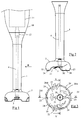
- FIG. 1 represents a household mixer comprising a housing 10 enclosing, in a manner known per se, a motor 11 shown diagrammatically in dashed lines in the figure.
- the motor 11 is arranged along the longitudinal axis of the housing 10 and has an output shaft provided with a rotary driver 12 passing through an opening in the lower part of the housing 10.
- a mixing stand comprising a tubular shaft 1 advantageously made of stainless steel or plastic, the tubular shaft 1 having an upper portion having a coupling piece for mounting the mixing foot on the housing 10.
- the lower part of the mixing base comprises a protective bell 2 enclosing a mixing tool 3 rotated by a shaft 4 extending inside the tubular shaft 1 and whose upper end comes to couple with the shaft.
- rotary drive 12 of the housing 10 The lower part of the mixing base comprises a protective bell 2 enclosing a mixing tool 3 rotated by a shaft 4 extending inside the tubular shaft 1 and whose upper end comes to couple with the shaft.
- the mixing tool 3 comprises, in a manner known per se, a hub 30 arranged orthogonally to the shaft 4 and extending on one side by a first knife 31 directed downwards and another side by a second knife 32 directed towards the top of the bell 2, the second knife 32 being larger than the first knife 31.
- the protective bell 2 advantageously comprises a peripheral wall of substantially circular cross section, with a diameter of about 65 mm, and the shaft 4 is eccentric with respect to the center of the protective bell 2, of about 5 mm .
- the protection bell 2 thus delimits a mixing chamber 20 slightly offset axially with respect to the mixing tool 3 so that the transverse plane, represented by the line VV in FIG. 3, divides the mixing chamber 20 into a first one. zone 20A at which the peripheral wall of the protection bell 2 is relatively close to the mixing tool 3 and a second zone 20B in which the peripheral wall of the protection bell 2 is further away from the mixing tool 3.
- the peripheral wall of the protective bell 2 comprises, in the second zone 20B of the mixing chamber 20, a suction opening 21 and a discharge opening 22 distinct.
- the suction opening is constituted by a notch 21 whose edge originates near the transverse plane VV of the protective bell 2 and which extends essentially in the second zone of the chamber 20, the notch 21 having a width of the order of 30 mm and a height of about 10 mm, the upper edge of the notch 21 arriving substantially at the hub 30 of the tool.
- the discharge opening is constituted by a notch 22 having dimensions similar to that of the suction indentation 21 and arranged opposite the latter so that the suction indentations 21 and discharge 22 are arranged symmetrically with respect to the longitudinal plane represented by the line IV-IV, while being offset with respect to the transverse plane VV passing through the shaft 4.
- the protective bell 2 also has secondary notches 23 disposed in the longitudinal axis of the bell 2, these secondary notches 23 having a smaller passage section than the suction and discharge notches 21.
- the secondary indentations have a height of the order of 7 mm and a width of about 25 mm.
- the peripheral wall of the protection bell 2 has, alternately with the indented portions 21, 22, 23, four lobes 24 extending below the level of the tool mixer 3 and having a flat bottom edge allowing the mixing foot to rest in equilibrium on the bottom of a container.
- the inner surface of the protective bell 2 preferably comprises a profiled relief element constituting a deflector 25 which reduces the flow section of the upstream mixing flow. of the suction indentation 21.
- Such a mixer has the advantage of providing excellent mixing efficiency, especially for food materials such as carrots. Indeed, the rotation of the mixing tool generates a large flow of traffic between the suction and discharge notches which is accentuated by the presence of the deflector, the latter reducing the passage section and generating, by venturi effect, a depression causing aspiration to favor the entry of the liquid at the suction indentation.
- the mixing foot thus functions as a pump in which a primary flow is sucked by the suction notch and is partly rejected by the discharge notch disposed facing and partly deflected towards the first zone of the protective bell in which the materials are mixed between the lobes and blades of the mixing tool.
- the mixing flow that engages in the first zone of the protection bell is initially compressed, because of the gradual restriction of the passage section, which promotes the mixing of food.
- the presence of the secondary notches has the advantage of reducing the suction effect, occurring when the mixing pad is applied to the bottom of a container, allowing secondary streams to enter or exit the bell of the container. suction, these secondary notches also to optimize the mixing of the liquid and thus the efficiency of mixing.
- the shape of the protective bell may be oblong.
- the mixing foot may be integral with the motor housing.
Landscapes
- Engineering & Computer Science (AREA)
- Mechanical Engineering (AREA)
- Food Science & Technology (AREA)
- Food-Manufacturing Devices (AREA)
- Mixers Of The Rotary Stirring Type (AREA)
Abstract
Description
La présente invention concerne le domaine technique général des mixeurs ménagers du type plongeant et se rapporte plus particulièrement à un pied de mixage destiné à broyer des matières alimentaires immergées dans un liquide. De tels pieds de mixage sont bien connus et utilisés couramment. Ils sont accouplés à un boîtier renfermant un moteur et comprennent un fût cylindrique dont la partie inférieure comporte une cloche renfermant un outil de mixage solidaire d'un arbre dont l'extrémité supérieure est accouplée à un arbre de sortie du moteur. Entraîné à grande vitesse, l'outil est plongé à l'intérieur des aliments à préparer et il coupe, mélange, émulsionne, etc.The present invention relates to the general technical field of household mixers of the diving type and relates more particularly to a mixing stand for grinding food materials immersed in a liquid. Such mixing stands are well known and commonly used. They are coupled to a housing containing a motor and comprise a cylindrical barrel whose lower part comprises a bell containing a mixing tool integral with a shaft whose upper end is coupled to an output shaft of the motor. Driven at high speed, the tool is dipped inside the food to be prepared and it cuts, mixes, emulsifies, etc.
Il est connu, du document
L'invention qui suit vise à pallier ces inconvénients en proposant un pied de mixage de forme relativement simple, qui soit économique à réaliser et qui offre une grande efficacité de mixage des aliments.The invention which follows aims to overcome these disadvantages by providing a mixing foot relatively simple form, which is economical to achieve and offers a high mixing efficiency of food.
Le but de l'invention est atteint par un pied de mixage comprenant une cloche de protection comportant une paroi périphérique délimitant une chambre de mixage autour d'un outil rotatif, l'outil rotatif étant solidaire d'un arbre traversant la cloche de protection et destiné à être entraîné par un moteur, l'arbre étant monté de façon excentrée par rapport à la cloche de protection de sorte que le plan transversal, passant par l'arbre et perpendiculaire à la direction d'excentration de l'arbre par rapport à la cloche de protection, divise la chambre de mixage en une première zone et une deuxième zone, la paroi périphérique de la cloche de protection étant plus proche de l'outil rotatif dans la première zone que dans la deuxième zone, caractérisé en ce que la paroi périphérique de la cloche de protection comporte au moins une ouverture d'aspiration et une ouverture de refoulement, distinctes, disposées dans la deuxième zone de la chambre de mixage.The object of the invention is achieved by a mixing pad comprising a protective bell having a peripheral wall delimiting a mixing chamber around a rotary tool, the rotary tool being integral with a shaft passing through the protective bell and designed to be driven by a motor, the shaft being eccentrically mounted with respect to the protection bell so that the transverse plane passing through the shaft and perpendicular to the eccentric direction of the shaft relative to the protective bell, divides the mixing chamber into a first zone and a second zone, the peripheral wall of the protection bell being closer to the rotary tool in the first zone; zone in the second zone, characterized in that the peripheral wall of the protective bell has at least one separate suction opening and discharge opening arranged in the second zone of the mixing chamber.
Selon une autre caractéristique de l'invention, les ouvertures d'aspiration et de refoulement sont disposées sensiblement en vis-à-vis.According to another characteristic of the invention, the suction and discharge openings are arranged substantially vis-à-vis.
Selon une autre caractéristique de l'invention, les ouvertures d'aspiration et de refoulement sont formées par des échancrures réalisées dans la partie inférieure de la paroi périphérique de la cloche de protection.According to another characteristic of the invention, the suction and discharge openings are formed by notches made in the lower part of the peripheral wall of the protective bell.
Selon une autre caractéristique de l'invention, les ouvertures d'aspiration et de refoulement sont délimitées latéralement par des lobes dont le bord inférieur s'étend en dessous du point le plus bas de l'outil rotatif.According to another characteristic of the invention, the suction and discharge openings are delimited laterally by lobes whose lower edge extends below the lowest point of the rotary tool.
Selon une autre caractéristique de l'invention, les échancrures formant les ouvertures d'aspiration et de refoulement débutent sensiblement au niveau du plan transversal de la cloche de protection passant par l'arbre.According to another characteristic of the invention, the notches forming the suction and discharge openings begin substantially at the transverse plane of the protective bell passing through the shaft.
Selon encore une autre caractéristique de l'invention, l'outil rotatif comporte un moyeu fixé à l'extrémité de l'arbre se prolongeant d'un côté par un premier couteau s'étendant obliquement vers l'extrémité ouverte de la cloche de protection et un second couteau s'étendant obliquement vers l'extrémité fermée de la cloche de protection, les échancrures remontant sensiblement jusqu'à hauteur du moyeu de l'outil rotatif.According to yet another characteristic of the invention, the rotary tool comprises a hub attached to the end of the shaft extending on one side by a first knife extending obliquely towards the open end of the protective bell and a second knife extending obliquely towards the closed end of the protective bell, the notches extending substantially up to the hub of the rotary tool.
Selon encore une autre caractéristique de l'invention, la paroi périphérique de la cloche de protection comporte des ouvertures supplémentaires présentant une section de passage plus réduite que les sections de passage des ouvertures d'aspiration et de refoulement.According to yet another characteristic of the invention, the peripheral wall of the protective bell has additional openings having a smaller passage section than the passage sections of the suction and discharge openings.
Selon encore une autre caractéristique de l'invention, les ouvertures supplémentaires sont constituées par deux échancrures réalisées dans la partie inférieure de la paroi périphérique de la cloche de protection et disposées en vis-à-vis selon le plan longitudinal de la cloche de protection.According to yet another characteristic of the invention, the additional openings are constituted by two notches made in the lower part of the peripheral wall of the protective bell and disposed vis-à-vis along the longitudinal plane of the protective bell.
Selon encore une autre caractéristique de l'invention, la surface intérieure de la cloche de protection comporte un élément en relief disposé en amont de l'ouverture d'aspiration par rapport au sens de rotation de l'outil de sorte que la section de passage du flux de mixage est progressivement réduite en amont de l'ouverture d'aspiration.According to yet another characteristic of the invention, the inner surface of the protective bell has a raised element disposed upstream of the suction opening relative to the direction of rotation of the tool so that the passage section of the mixing stream is progressively reduced upstream of the suction opening.
Selon une autre caractéristique de l'invention, la cloche de protection est de forme générale demi-sphérique.According to another characteristic of the invention, the protective bell is generally half-spherical.
L'invention concerne également un appareil électroménager comportant un boîtier renfermant un moteur électrique, caractérisé en ce que l'appareil comporte un pied de mixage tel que précédemment décrit.The invention also relates to a household appliance comprising a housing enclosing an electric motor, characterized in that the apparatus comprises a mixing stand as previously described.
On comprendra mieux les buts, aspects et avantages de la présente invention, d'après la description donnée ci-après d'un mode particulier de réalisation de l'invention, présenté à titre d'exemple non limitatif, en se référant aux dessins annexés dans lesquels :
- la figure 1 est une vue de côté d'un mixeur ménager muni d'un pied de mixage selon un mode particulier de réalisation de l'invention ;
- la figure 2 est une vue de côté, selon la flèche Il, du pied de mixage de la figure 1 ;
- la figure 3 est une vue de dessous du pied de mixage de la figure 2 ;
- les figures 4 et 5 sont respectivement des vues en coupe longitudinale et transversale selon les lignes IV-IV et V-V de la figure 3 ;
- les figures 6 et 7 sont des vues en perspective du pied de mixage de la figure 2.
- Figure 1 is a side view of a household mixer provided with a mixing foot according to a particular embodiment of the invention;
- Figure 2 is a side view, along the arrow II, the mixing foot of Figure 1;
- Figure 3 is a bottom view of the mixing foot of Figure 2;
- Figures 4 and 5 are respectively longitudinal and transverse sectional views along the lines IV-IV and VV of Figure 3;
- Figures 6 and 7 are perspective views of the mixing stand of Figure 2.
Seuls les éléments nécessaires à la compréhension de l'invention ont été représentés. Pour faciliter la lecture des dessins les mêmes éléments portent les mêmes références d'une figure à l'autre.Only the elements necessary for the understanding of the invention have been represented. To facilitate the reading of the drawings, the same elements bear the same references from one figure to another.
La figure 1 représente un mixeur ménager comportant un boîtier 10 renfermant, de manière connue en soi, un moteur 11 représenté schématiquement en pointillé sur la figure. Le moteur 11 est agencé selon l'axe longitudinal du boîtier 10 et possède un arbre de sortie muni d'un entraîneur rotatif 12 traversant une ouverture pratiquée dans la partie inférieure du boîtier 10.FIG. 1 represents a household mixer comprising a
Sur la partie inférieure du boîtier 10 est monté, de façon amovible ou non, un pied de mixage comprenant un fût tubulaire 1 réalisé avantageusement en acier inox ou en matière plastique, le fût tubulaire 1 ayant une partie supérieure comportant une pièce d'accouplement assurant le montage du pied de mixage sur le boîtier 10.On the lower part of the
La partie inférieure du pied de mixage comporte une cloche de protection 2 renfermant un outil de mixage 3 entraîné en rotation par un arbre 4 s'étendant à l'intérieur du fût tubulaire 1 et dont l'extrémité supérieure vient s'accoupler avec l'entraîneur rotatif 12 du boîtier 10.The lower part of the mixing base comprises a
Conformément aux figures 2 à 5, l'outil de mixage 3 comporte, de manière connue en soi, un moyeu 30 disposé orthogonalement à l'arbre 4 et se prolongeant d'un côté par un premier couteau 31 dirigé vers le bas et de l'autre côté par un second couteau 32 dirigé vers le sommet de la cloche 2, le second couteau 32 étant plus grand que le premier couteau 31.According to FIGS. 2 to 5, the
La cloche de protection 2 comporte avantageusement une paroi périphérique de section sensiblement circulaire, d'un diamètre de l'ordre de 65 mm, et l'arbre 4 est excentré par rapport au centre de la cloche de protection 2, d'environ 5 mm.The
La cloche de protection 2 délimite ainsi une chambre de mixage 20 légèrement décalée axialement par rapport à l'outil de mixage 3 de sorte que le plan transversal, représenté par la ligne V-V sur la figure 3, divise la chambre de mixage 20 en une première zone 20A au niveau de laquelle la paroi périphérique de la cloche de protection 2 est relativement proche de l'outil de mixage 3 et une seconde zone 20B dans laquelle la paroi périphérique de la cloche de protection 2 est plus éloignée de l'outil de mixage 3.The
Plus particulièrement selon l'invention, la paroi périphérique de la cloche de protection 2 comporte, dans la seconde zone 20B de la chambre de mixage 20, une ouverture d'aspiration 21 et une ouverture de refoulement 22 distinctes. L'ouverture d'aspiration est constituée par une échancrure 21 dont le bord prend naissance à proximité du plan transversal V-V de la cloche de protection 2 et qui s'étend essentiellement dans la seconde zone de la chambre 20, l'échancrure 21 présentant une largeur de l'ordre de 30 mm et une hauteur de l'ordre de 10 mm, le bord supérieur de l'échancrure 21 arrivant sensiblement à hauteur du moyeu 30 de l'outil.More particularly according to the invention, the peripheral wall of the
L'ouverture de refoulement est constituée par une échancrure 22 présentant des dimensions semblables à celle de l'échancrure d'aspiration 21 et disposée en vis-à-vis de cette dernière de sorte que les échancrures d'aspiration 21 et de refoulement 22 sont disposées symétriquement par rapport au plan longitudinal représenté par la ligne IV-IV, tout en étant décalées par rapport au plan transversal V-V passant par l'arbre 4.The discharge opening is constituted by a
De manière avantageuse, la cloche de protection 2 comporte également des échancrures secondaires 23 disposées dans l'axe longitudinal de la cloche 2, ces échancrures secondaires 23 possédant une plus faible section de passage que les échancrures d'aspiration 21 et de refoulement 22. A titre d'exemple, les échancrures secondaires présentent une hauteur de l'ordre de 7 mm et une largeur de l'ordre de 25 mm.Advantageously, the
Comme on peut bien le voir sur les figures 4 à 7, la paroi périphérique de la cloche de protection 2 présente, en alternance avec les parties échancrées 21, 22, 23, quatre lobes 24 s'étendant en dessous du niveau de l'outil de mixage 3 et présentant un bord inférieur plat permettant au pied de mixage de reposer en équilibre sur le fond d'un récipient.As can clearly be seen in FIGS. 4 to 7, the peripheral wall of the
Afin d'augmenter le débit du flux entrant dans la cloche de protection 2, la surface intérieure de la cloche de protection 2 comporte préférentiellement un élément en relief, profilé, constituant un déflecteur 25 venant réduire la section de passage du flux de mixage en amont de l'échancrure d'aspiration 21.In order to increase the flow rate of the flow entering the
Un tel pied de mixage présente l'avantage de procurer une excellente efficacité de mixage, notamment pour les matières alimentaires telles que les carottes. En effet, la rotation de l'outil de mixage génère un important flux de circulation entre les échancrures d'aspiration et de refoulement qui est accentué par la présence du déflecteur, ce dernier réduisant la section de passage et générant, par effet venturi, une dépression provoquant une aspiration favorisant l'entrée du liquide au niveau de l'échancrure d'aspiration.Such a mixer has the advantage of providing excellent mixing efficiency, especially for food materials such as carrots. Indeed, the rotation of the mixing tool generates a large flow of traffic between the suction and discharge notches which is accentuated by the presence of the deflector, the latter reducing the passage section and generating, by venturi effect, a depression causing aspiration to favor the entry of the liquid at the suction indentation.
Le pied de mixage fonctionne donc comme une pompe dans laquelle un flux primaire est aspiré par l'échancrure d'aspiration puis est pour partie rejeté par l'échancrure de refoulement disposée en regard et pour partie dévié vers la première zone de la cloche de protection dans laquelle les matières alimentaires sont mixées entre les lobes et les lames de l'outil de mixage. Le flux de mixage qui s'engage dans la première zone de la cloche de protection subit dans un premier temps une compression, du fait de la restriction progressive de la section de passage, qui favorise le mixage des aliments.The mixing foot thus functions as a pump in which a primary flow is sucked by the suction notch and is partly rejected by the discharge notch disposed facing and partly deflected towards the first zone of the protective bell in which the materials are mixed between the lobes and blades of the mixing tool. The mixing flow that engages in the first zone of the protection bell is initially compressed, because of the gradual restriction of the passage section, which promotes the mixing of food.
La présence des échancrures secondaires présente l'avantage de réduire l'effet de succion, se produisant lorsque le pied de mixage est appliqué au fond d'un récipient, en permettant à des flux secondaires d'entrer ou de sortir de la cloche d'aspiration, ces échancrures secondaires permettant également d'optimiser le brassage du liquide et donc l'efficacité du mixage.The presence of the secondary notches has the advantage of reducing the suction effect, occurring when the mixing pad is applied to the bottom of a container, allowing secondary streams to enter or exit the bell of the container. suction, these secondary notches also to optimize the mixing of the liquid and thus the efficiency of mixing.
Bien entendu, l'invention n'est nullement limitée au mode de réalisation décrit et illustré qui n'a été donné qu'à titre d'exemple. Des modifications restent possibles, notamment du point de vue de la constitution des divers éléments ou par substitution d'équivalents techniques, sans sortir pour autant du domaine de protection de l'invention.Of course, the invention is not limited to the embodiment described and illustrated which has been given by way of example. Modifications are possible, particularly from the point of view of the constitution of the various elements or by substitution of technical equivalents, without departing from the scope of protection of the invention.
Ainsi, dans une variante de réalisation non représentée, la forme de la cloche de protection pourra être oblongue.Thus, in an alternative embodiment not shown, the shape of the protective bell may be oblong.
Ainsi, dans une autre variante de réalisation le pied de mixage pourra être solidaire du boîtier moteur.Thus, in another alternative embodiment the mixing foot may be integral with the motor housing.
Claims (11)
Applications Claiming Priority (1)
| Application Number | Priority Date | Filing Date | Title |
|---|---|---|---|
| FR0603943A FR2900558B1 (en) | 2006-05-03 | 2006-05-03 | MIXING FOOT WITH A PARTICULAR SHAPE PROTECTION BELL AND HOUSEHOLD MIXER PROVIDED WITH SUCH A MIXING FOOT |
Publications (3)
| Publication Number | Publication Date |
|---|---|
| EP1854390A2 true EP1854390A2 (en) | 2007-11-14 |
| EP1854390A3 EP1854390A3 (en) | 2008-08-13 |
| EP1854390B1 EP1854390B1 (en) | 2010-04-07 |
Family
ID=37634689
Family Applications (1)
| Application Number | Title | Priority Date | Filing Date |
|---|---|---|---|
| EP20070356052 Ceased EP1854390B1 (en) | 2006-05-03 | 2007-04-19 | Mixing base equipped with a protective cover with a specific shape and domestic mixer equipped with such a mixing base |
Country Status (4)
| Country | Link |
|---|---|
| EP (1) | EP1854390B1 (en) |
| CN (1) | CN101066194B (en) |
| DE (1) | DE602007005715D1 (en) |
| FR (1) | FR2900558B1 (en) |
Cited By (2)
| Publication number | Priority date | Publication date | Assignee | Title |
|---|---|---|---|---|
| EP2767203A1 (en) * | 2013-02-14 | 2014-08-20 | Alex Gort-Barten | Hand blender |
| DE102013219834A1 (en) | 2013-09-30 | 2015-04-02 | BSH Bosch und Siemens Hausgeräte GmbH | Tool for a kitchen appliance with separating ribs |
Families Citing this family (7)
| Publication number | Priority date | Publication date | Assignee | Title |
|---|---|---|---|---|
| GB2469639B (en) | 2009-04-21 | 2016-11-02 | Kenwood Ltd | Wand attachments for hand-held electric blenders |
| EP2564745A1 (en) * | 2011-09-01 | 2013-03-06 | Koninklijke Philips Electronics N.V. | A lid for a food processor |
| CN202589333U (en) * | 2012-02-28 | 2012-12-12 | 泓首翔电器(深圳)有限公司 | Portable blender |
| WO2014054420A1 (en) | 2012-10-05 | 2014-04-10 | 株式会社村田製作所 | Light sensor |
| JP6251887B2 (en) * | 2013-09-02 | 2017-12-27 | パナソニックIpマネジメント株式会社 | Mixer unit and hand blender |
| FR3048600B1 (en) * | 2016-03-11 | 2018-04-13 | Seb S.A. | MIXING FOOT COMPRISING A COUPLING FLANGE FOR ITS REMOVABLE MOUNTING ON A MOTOR HOUSING |
| DE102019206029B4 (en) * | 2019-04-26 | 2022-02-10 | De'longhi Braun Household Gmbh | Kitchen utensil and accessory for sealing a protective hood of a kitchen utensil |
Citations (2)
| Publication number | Priority date | Publication date | Assignee | Title |
|---|---|---|---|---|
| EP0324115A1 (en) * | 1987-12-31 | 1989-07-19 | Moulinex | Mixing device for domestic use |
| US6523990B1 (en) * | 2002-08-12 | 2003-02-25 | Main Power Electrical Factory Ltd. | Hand blender |
Family Cites Families (1)
| Publication number | Priority date | Publication date | Assignee | Title |
|---|---|---|---|---|
| FR2891449B1 (en) * | 2005-10-04 | 2007-11-23 | Seb Sa | MIXER FOOT AND MIXER MIXER TYPE OF DIVING PROVIDED WITH SUCH A FOOT OF MIXING |
-
2006
- 2006-05-03 FR FR0603943A patent/FR2900558B1/en not_active Expired - Fee Related
-
2007
- 2007-04-19 EP EP20070356052 patent/EP1854390B1/en not_active Ceased
- 2007-04-19 DE DE200760005715 patent/DE602007005715D1/en active Active
- 2007-04-24 CN CN2007100983845A patent/CN101066194B/en active Active
Patent Citations (2)
| Publication number | Priority date | Publication date | Assignee | Title |
|---|---|---|---|---|
| EP0324115A1 (en) * | 1987-12-31 | 1989-07-19 | Moulinex | Mixing device for domestic use |
| US6523990B1 (en) * | 2002-08-12 | 2003-02-25 | Main Power Electrical Factory Ltd. | Hand blender |
Cited By (3)
| Publication number | Priority date | Publication date | Assignee | Title |
|---|---|---|---|---|
| EP2767203A1 (en) * | 2013-02-14 | 2014-08-20 | Alex Gort-Barten | Hand blender |
| DE102013219834A1 (en) | 2013-09-30 | 2015-04-02 | BSH Bosch und Siemens Hausgeräte GmbH | Tool for a kitchen appliance with separating ribs |
| WO2015043919A1 (en) * | 2013-09-30 | 2015-04-02 | BSH Bosch und Siemens Hausgeräte GmbH | Tool for a kitchen appliance, having separating ribs |
Also Published As
| Publication number | Publication date |
|---|---|
| EP1854390A3 (en) | 2008-08-13 |
| DE602007005715D1 (en) | 2010-05-20 |
| FR2900558A1 (en) | 2007-11-09 |
| FR2900558B1 (en) | 2008-06-06 |
| CN101066194A (en) | 2007-11-07 |
| EP1854390B1 (en) | 2010-04-07 |
| CN101066194B (en) | 2011-02-09 |
Similar Documents
| Publication | Publication Date | Title |
|---|---|---|
| EP1854390B1 (en) | Mixing base equipped with a protective cover with a specific shape and domestic mixer equipped with such a mixing base | |
| EP1772087B1 (en) | Mixing rod and domestic mixing device of the immersing type with such a mixing rod | |
| EP1529471B1 (en) | Mixing rod and domestic mixing device of the immersing type with such a mixing rod | |
| CA2837644C (en) | Tool for cutting food into pieces | |
| EP2071989B1 (en) | Work container for a household cooking appliance and appliance equipped with such a container | |
| EP1900315B1 (en) | Immersed domestic mixer comprising a work tool in the shape of an Archimedes screw | |
| EP1858633B1 (en) | Blender-type electrical cooking appliance comprising a stirrer | |
| WO2014037663A1 (en) | Household food preparation apparatus comprising a dough-mixing hook driven in a planetary motion | |
| FR2917000A1 (en) | Circular saw for cutting wooden plate, has duct connecting release orifice and inlet opening, where duct is oriented such that axis is directed towards base of concave curved wall that closes ends of reception volume | |
| EP1935302B1 (en) | Storage case for immersed domestic mixer | |
| FR2997282A1 (en) | Mixer rod for use in e.g. plunging mixer for crushing food materials immersed in liquid, has protection cover comprising peripheral wall whose internal surface has edges provided on sides of slot and radially shifted relative to each other | |
| EP2259707B1 (en) | Domestic cooking appliance for making liquid concoctions | |
| FR2682026A1 (en) | Spatula, especially for culinary use | |
| EP2498654A1 (en) | Beater for a food preparation appliance and device provided with such a beater | |
| EP2259708B1 (en) | Domestic cooking appliance for making liquid concoctions | |
| EP2096342A1 (en) | Tap for dispensing the food contained in a container and household cooking appliance comprising such a tap | |
| WO2016203132A1 (en) | Assembly for starter | |
| EP1413770A1 (en) | Centrifugal pump | |
| FR2814057A1 (en) | Cooking appliance design, has removable cassette, fitting in recess in base, which contains electric motor which can be connected to work appliance or tool via output shaft |
Legal Events
| Date | Code | Title | Description |
|---|---|---|---|
| PUAI | Public reference made under article 153(3) epc to a published international application that has entered the european phase |
Free format text: ORIGINAL CODE: 0009012 |
|
| AK | Designated contracting states |
Kind code of ref document: A2 Designated state(s): AT BE BG CH CY CZ DE DK EE ES FI FR GB GR HU IE IS IT LI LT LU LV MC MT NL PL PT RO SE SI SK TR |
|
| AX | Request for extension of the european patent |
Extension state: AL BA HR MK YU |
|
| PUAL | Search report despatched |
Free format text: ORIGINAL CODE: 0009013 |
|
| AK | Designated contracting states |
Kind code of ref document: A3 Designated state(s): AT BE BG CH CY CZ DE DK EE ES FI FR GB GR HU IE IS IT LI LT LU LV MC MT NL PL PT RO SE SI SK TR |
|
| AX | Request for extension of the european patent |
Extension state: AL BA HR MK RS |
|
| 17P | Request for examination filed |
Effective date: 20090209 |
|
| AKX | Designation fees paid |
Designated state(s): DE |
|
| GRAP | Despatch of communication of intention to grant a patent |
Free format text: ORIGINAL CODE: EPIDOSNIGR1 |
|
| GRAS | Grant fee paid |
Free format text: ORIGINAL CODE: EPIDOSNIGR3 |
|
| GRAA | (expected) grant |
Free format text: ORIGINAL CODE: 0009210 |
|
| AK | Designated contracting states |
Kind code of ref document: B1 Designated state(s): DE |
|
| REF | Corresponds to: |
Ref document number: 602007005715 Country of ref document: DE Date of ref document: 20100520 Kind code of ref document: P |
|
| PLBE | No opposition filed within time limit |
Free format text: ORIGINAL CODE: 0009261 |
|
| STAA | Information on the status of an ep patent application or granted ep patent |
Free format text: STATUS: NO OPPOSITION FILED WITHIN TIME LIMIT |
|
| 26N | No opposition filed |
Effective date: 20110110 |
|
| PGFP | Annual fee paid to national office [announced via postgrant information from national office to epo] |
Ref country code: DE Payment date: 20140411 Year of fee payment: 8 |
|
| REG | Reference to a national code |
Ref country code: DE Ref legal event code: R119 Ref document number: 602007005715 Country of ref document: DE |
|
| PG25 | Lapsed in a contracting state [announced via postgrant information from national office to epo] |
Ref country code: DE Free format text: LAPSE BECAUSE OF NON-PAYMENT OF DUE FEES Effective date: 20151103 |