EP1853401B1 - Collet and lock nut assembly - Google Patents
Collet and lock nut assembly Download PDFInfo
- Publication number
- EP1853401B1 EP1853401B1 EP06736355A EP06736355A EP1853401B1 EP 1853401 B1 EP1853401 B1 EP 1853401B1 EP 06736355 A EP06736355 A EP 06736355A EP 06736355 A EP06736355 A EP 06736355A EP 1853401 B1 EP1853401 B1 EP 1853401B1
- Authority
- EP
- European Patent Office
- Prior art keywords
- collet
- lock nut
- assembly
- groove
- nose
- Prior art date
- Legal status (The legal status is an assumption and is not a legal conclusion. Google has not performed a legal analysis and makes no representation as to the accuracy of the status listed.)
- Not-in-force
Links
Images

Classifications
-
- B—PERFORMING OPERATIONS; TRANSPORTING
- B23—MACHINE TOOLS; METAL-WORKING NOT OTHERWISE PROVIDED FOR
- B23B—TURNING; BORING
- B23B31/00—Chucks; Expansion mandrels; Adaptations thereof for remote control
- B23B31/02—Chucks
- B23B31/10—Chucks characterised by the retaining or gripping devices or their immediate operating means
- B23B31/12—Chucks with simultaneously-acting jaws, whether or not also individually adjustable
- B23B31/20—Longitudinally-split sleeves, e.g. collet chucks
- B23B31/201—Characterized by features relating primarily to remote control of the gripping means
- B23B31/2012—Threaded cam actuator
- B23B31/20125—Axially fixed cam, moving jaws
-
- B—PERFORMING OPERATIONS; TRANSPORTING
- B23—MACHINE TOOLS; METAL-WORKING NOT OTHERWISE PROVIDED FOR
- B23B—TURNING; BORING
- B23B2231/00—Details of chucks, toolholder shanks or tool shanks
- B23B2231/20—Collet chucks
- B23B2231/201—Operating surfaces of collets, i.e. the surface of the collet acted on by the operating means
-
- Y—GENERAL TAGGING OF NEW TECHNOLOGICAL DEVELOPMENTS; GENERAL TAGGING OF CROSS-SECTIONAL TECHNOLOGIES SPANNING OVER SEVERAL SECTIONS OF THE IPC; TECHNICAL SUBJECTS COVERED BY FORMER USPC CROSS-REFERENCE ART COLLECTIONS [XRACs] AND DIGESTS
- Y10—TECHNICAL SUBJECTS COVERED BY FORMER USPC
- Y10T—TECHNICAL SUBJECTS COVERED BY FORMER US CLASSIFICATION
- Y10T279/00—Chucks or sockets
- Y10T279/17—Socket type
- Y10T279/17291—Resilient split socket
- Y10T279/17299—Threaded cam sleeve
-
- Y—GENERAL TAGGING OF NEW TECHNOLOGICAL DEVELOPMENTS; GENERAL TAGGING OF CROSS-SECTIONAL TECHNOLOGIES SPANNING OVER SEVERAL SECTIONS OF THE IPC; TECHNICAL SUBJECTS COVERED BY FORMER USPC CROSS-REFERENCE ART COLLECTIONS [XRACs] AND DIGESTS
- Y10—TECHNICAL SUBJECTS COVERED BY FORMER USPC
- Y10T—TECHNICAL SUBJECTS COVERED BY FORMER US CLASSIFICATION
- Y10T279/00—Chucks or sockets
- Y10T279/17—Socket type
- Y10T279/17411—Spring biased jaws
- Y10T279/17487—Moving-cam actuator
- Y10T279/17504—Threaded cam sleeve
-
- Y—GENERAL TAGGING OF NEW TECHNOLOGICAL DEVELOPMENTS; GENERAL TAGGING OF CROSS-SECTIONAL TECHNOLOGIES SPANNING OVER SEVERAL SECTIONS OF THE IPC; TECHNICAL SUBJECTS COVERED BY FORMER USPC CROSS-REFERENCE ART COLLECTIONS [XRACs] AND DIGESTS
- Y10—TECHNICAL SUBJECTS COVERED BY FORMER USPC
- Y10T—TECHNICAL SUBJECTS COVERED BY FORMER US CLASSIFICATION
- Y10T279/00—Chucks or sockets
- Y10T279/17—Socket type
- Y10T279/17411—Spring biased jaws
- Y10T279/17529—Fixed cam and moving jaws
- Y10T279/17538—Threaded-sleeve actuator
-
- Y—GENERAL TAGGING OF NEW TECHNOLOGICAL DEVELOPMENTS; GENERAL TAGGING OF CROSS-SECTIONAL TECHNOLOGIES SPANNING OVER SEVERAL SECTIONS OF THE IPC; TECHNICAL SUBJECTS COVERED BY FORMER USPC CROSS-REFERENCE ART COLLECTIONS [XRACs] AND DIGESTS
- Y10—TECHNICAL SUBJECTS COVERED BY FORMER USPC
- Y10T—TECHNICAL SUBJECTS COVERED BY FORMER US CLASSIFICATION
- Y10T29/00—Metal working
- Y10T29/49—Method of mechanical manufacture
- Y10T29/49826—Assembling or joining
- Y10T29/49863—Assembling or joining with prestressing of part
- Y10T29/49876—Assembling or joining with prestressing of part by snap fit
-
- Y—GENERAL TAGGING OF NEW TECHNOLOGICAL DEVELOPMENTS; GENERAL TAGGING OF CROSS-SECTIONAL TECHNOLOGIES SPANNING OVER SEVERAL SECTIONS OF THE IPC; TECHNICAL SUBJECTS COVERED BY FORMER USPC CROSS-REFERENCE ART COLLECTIONS [XRACs] AND DIGESTS
- Y10—TECHNICAL SUBJECTS COVERED BY FORMER USPC
- Y10T—TECHNICAL SUBJECTS COVERED BY FORMER US CLASSIFICATION
- Y10T29/00—Metal working
- Y10T29/53—Means to assemble or disassemble
- Y10T29/53704—Means to assemble or disassemble tool chuck and tool
Definitions
- the present invention relates to chucks and sockets and, more particularly, to a collet and lock nut assembly for use with machine tools. Most particularly, the invention relates to a collet and lock nut assembly having a lock nut that allows easy, clip-in entry of the collet, while ensuring removal of the collet and cutting tool from the chuck.
- Collets for use in tool-holding chuck assemblies are well known.
- Such collets generally comprise a tubular body formed from a plurality of elongated, flexible steel fingers.
- the fingers are separated by longitudinal collet saw slots that impart some degree of radial flexibility to the collet, which allows the collet to selectively grip the shank of a cutting tool, such as a drill bit.
- Adjacent gripping fingers are interconnected by an alternating pattern of metal webs to form a one-piece collet body.
- the collet body is inserted in a complementary-shaped opening in a chuck shaft so that a distal end of the collet body projects out of the shaft.
- An annular lock nut having an inner diameter screw thread that matches an outer diameter screw thread on the shaft is then installed over the shaft and distal end of the collet body.
- the lock nut has a nose ring with a frustoconical cam surface that engages the distal end of the collet body and squeezes it radially inwardly as the lock nut is screwed onto the chuck shaft.
- the radial compression that the lock nut applies to the distal end of the collet body flexes the body inwardly, creating a gripping force between the inner diameter of the collet body and a tool shank inserted therein.
- the US Patent No. 4,817,972 disclosing the features of the preamble of claims 1 and 8, discloses a collet chuck where a fastening nut is screwed down to the main body of the chuck for urging the fingers of the collet to engage and secure a tool shaft.
- the fastening nut is provided with a pair of opposing internal flanges which cooperate the gripping fingers of the collet to allow detachable connection of the collet with the fastening nut.
- the German Patent DE 900 030 discloses a mounting assembly for a cutting tool comprising a collet having a nose portion and a body portion separated by a flange.
- a locking nut has a plurality of fingers for retaining the shaft of a tool to be sucured,
- the locking nut has two retention tabs which match with two cutouts in the flange in the collet to provide a detachable connection.
- a collet and lock nut assembly is provided as defined in claims 1 and 8.
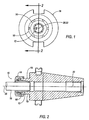
- FIGURE 1 is a front view of a collet and lock nut assembly mounted in a tool holder according to an embodiment of the invention
- FIGURE 2 is a cross-sectional view of the collet and lock nut assembly when mounted in the tool holder taken along line 2-2 in FIGURE 1 ;
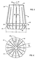
- FIGURE 3 is a side elevational view of the collet according to an embodiment of the invention.
- FIGURE 4 is a front view of the collet shown in FIGURE 3 ;
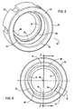
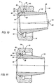
- FIGURE 5 is a rear perspective view of a lock nut according to an embodiment of the invention.
- FIGURE 6 is a rear view of the lock nut shown in FIGURE 5 ;
- FIGURE 7 is a cross-sectional view of the lock nut taken along line 7-7 in FIGURE 6 ;
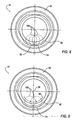
- FIGURE 8 is a rear view of the lock nut shown in FIGURE 5 illustrating the formation of clear portions and retaining tabs according to one method
- FIGURE 9 is a rear view of the lock nut shown in FIGURE 5 illustrating the formation of clear portions and retaining tabs according to an alternate method ;
- FIGURE 10 is a cross-sectional view of the collet and lock nut assembly in an unlocked position during partial assembly ;
- FIGURE 11 is a cross-sectional view of the collet and lock nut assembly in a locked position after complete assembly.
- FIGURES 1 and 2 there is illustrated in FIGURES 1 and 2 a collet and lock nut assembly shown generally at 10.
- the collet and lock nut assembly or chuck assembly 10 comprises a collet 12 and a lock nut 14.
- the collet 12 is adapted to receive a shank 16 of a cutting tool (not shown), while the collet and lock nut assembly 10 is adapted to be mounted to a chuck of a tool holder, shown generally at 18.
- a centerline 20 of the shank 16 is substantially aligned with a centerline 22 of the tool holder.
- the collet 12 is made from a resilient steel alloy and generally comprises a nose portion 24 and a body portion 26 separated by an annular recess or groove 28.
- the collet 12 includes a generally parallel array of slots 30 separated by webs or gripping fingers 32 having a radial dimension 33. The presence of the slots 30 allow the collet 12 to be radially compressed by the lock nut 14 to grip the shank 16 of the cutting tool.
- the outside surface of the nose portion 24 of the collet 12 includes an angled nose 34 that extends between the groove 28 and a front surface 36 of the collet 12. Specifically, the angled nose 34 tapers inwardly from the annular groove 28 to a front surface 36 of the collet 12.
- the angled nose 34 acts as a cam surface that cooperates with the lock nut 14 to radially compress the gripping fingers 32 into gripping engagement with the shank 16 of the cutting tool.
- a ledge 38 is provided behind the angled nose 34 to facilitate the removal of the collet 12 from the tool holder 18 via the lock nut 14.
- the angled nose 34 defines a nose diameter 35.
- the body portion 26 of the collet 12 is generally frustoconical in shape and tapers inwardly from the annular recess 28 to a back surface 40.
- the collet 12 further includes a cylindrically-shaped passageway 42 that is concentrically provided along an axis of rotation 44 of the collet 12 for receiving the shank 16 of the cutting tool, which may be, for example, a drill bit, or the like.
- the lock nut 14 is formed of an annular body 46 having a bore 48 that is concentrically provided along an axis of rotation 50 of the lock nut 14.
- the annular body 46 includes a front surface 52 and a rear surface 54.
- the inside of the lock nut 14 includes a first groove 56 generally centrally located within the inside of the lock nut 14.
- the first groove 56 includes a retaining wall 57 formed by the difference between the inner diameters of the bore 48 and the first groove 56.
- the inside of the lock nut 14 includes a second groove 58 that is situated between the first groove 56 and the front surface 52 of the lock nut 14.
- the second groove 58 has a relatively smaller diameter than the first groove 56.
- the inside of the lock nut 14 also includes an angled surface 64 extending between the second groove 58 and the front surface 52. Specifically, the angled surface 64 tapers inwardly from the second groove 58 to the front surface 52 of the lock nut 14.
- the angled surface 64 of the lock nut 14 acts as a cam surface that cooperates with the angled surface 34 of the collet 12 to radially compress the gripping fingers 32 of the collet 12 into gripping engagement with the shank 16 of the cutting tool.
- the annular body 46 of the lock nut 14 includes a screw thread 66 ( FIGURE 7 ) that circumscribes its inner diameter and is engageable with a screw thread 68 that circumscribes a chuck 70 of the tool holder 18, as shown in FIGURE 2 .
- the bore 48 of the lock nut 14 includes a plurality of retention tabs 72 and a corresponding number of clear portions 74.
- the lock nut 14 includes three retention tabs 72 and three clear portions 74 that are symmetrically positioned approximately 120° offset from each other about the concentric bore 48.
- the invention is not limited by the number of retention tabs and clear portions, and that the invention can be practiced with any desirable number of tabs and clear portion.
- the invention can be practiced with two tabs and clear portions positioned approximately 180° offset from each other.
- the invention can be practiced with four tabs and clear portions positioned approximately 90° offset from each other.
- each retention tab 72 has a radial dimension 76 that is preferably less than the radial dimension 33 of each gripping finger 32 of the collet 12 such that each retention tab 72 will engage only a single respective gripping finger 32.
- each retention tab 72 is preferably spaced about the bore 48 such that the retention tabs 72 will match up with the spacing of the gripping fingers 32.
- the retention tabs 72 are symmetrically disposed about the concentric bore 48. However, it will be appreciated that the retention tabs 72 do not have to symmetrically located about the bore 48, but can be located at any desired location that will match up with the spacing of the gripping fingers 32.
- the radial dimension 76 of one or more retention tabs 72 can vary.
- the radial dimension 76 of the two lower retention tabs 72 can be smaller than the radial dimension 76 of the top retention tab 72.
- varying the symmetry of the retention tabs 72 and/or the radial dimension 76 may disturb the natural balance of the assembly 10.
- the two retention tabs 72 can be arranged in a fashion where additional high speed balancing may not be necessary.
- the retention tabs 72 can be formed by machining the plurality of clear portions 74 about the bore 48.
- the machining of the clear portions 74 can be accomplished by using a variety of methods.
- one method for machining the clear portions 74 is shown in FIGURE 8 .
- a small diameter end mill 100 is used to perform a series of plunges from the rear of the lock nut 14 for form each clear portion 74.
- each plunge of the end mill 100 penetrates the bore 48 and stops after entering and produces an intersection mark 78 in the clear portion 74.
- four plunges were performed producing four intersection marks 78 in the clear portion 74 on the bore 48.
- the clear portions 74 can be machined by a single plunge of the small diameter end mill 100, and then moving the end mill 100 in a radial concentric path 80 around the rotation axis 50 of the lock nut 14 to form each clear portion 74.
- all the clear portions 74 can be produced without withdrawing the end mill 100 from the bore 48 of the lock nut 14 by interrupting the radial concentric path 80 of the end mill 100 as it moves around the rotation axis 50 of the lock nut 14.
- the collet 12 is hooked in an angular fashion such that groove wall 38 of the collet 12 engages the tab wall 62 of the second groove 58 of the lock nut 14.
- the rotation axis 44 of the collet 12 forms an angle 32 with respect to the rotation axis 50 of the lock nut 14 when the collet 12 is hooked in such an angular fashion.
- the widths of some or all of the slots 30 of the collet 12 are sufficiently deformed so as to effectively reduce the diameter 35 of the nose portion 24 of the collet 12 to enable the remainder of the relatively larger nose portion 24 to enter inside the relatively smaller bore 48 of the lock nut 14. Because portions of the bore 48 have been removed to produce the retention tabs 72, the clear portions 74 allow the nose portion 24 with the reduced diameter to clip inside the second groove 58 of the collet 12, thereby placing the collet and the lock nut assembly 10 in a locked position.
- the angled outer surface 34 of the collet 12 fully engages the angled surface 64 of the lock nut 14.
- the front surface 36 of the collet 12 is substantially flush with the front surface 52 of the lock nut 14. This flush relation is preferred because, upon removing a coolant ring (not shown) mounted to the front of the collet and lock nut assembly 10, the collet 12 is neither extending from nor recessed within the lock nut 16. Consequently, the length of the collet and lock nut assembly 10 is minimized, as desired.
- the retention tabs 72 of the lock nut 14 are received in the groove 28 of the collet 12.
- the surface 64 moves back enough to come into contact with the angled outer surface 34 of the collet 12 and the body portion 26 is drawn into the chuck 70.
- the retention tab 72 sufficiently moves backwards such that a tab wall 73 clears the groove walls 38, 101 of the collet 12.
- the tab wall 73 of the retention tab 72 supplies a surface sufficient enough to push against the groove wall 38 of the collet 12 and draw the collet 12, along with the cutting tool, out of the chuck 70 of the tool holder 18.
- three retention tabs 72 provide three concentric contact points to positively draw the collet 12 and cutting tool out of the chuck 70 of the tool holder 18. It will be appreciated that the greater number of retention tabs 72, the greater number of contact points to positively draw the collet 12 and cutting tool out of the chuck 70 of the tool holder 18.
- the retention tabs 72 enable the collet 12 to be easily removed from the lock nut 14 by applying pressure laterally in the direction of the arrow 84 against the body portion 26 of the collet 12.
- the pressure can be applied in any circumferential, lateral direction against the body portion 26 of the collet 12 (i.e., 360 degrees about the body portion 26 of the collet 12), unlike conventional assemblies that require the pressure to be applied in a specific direction against the collet.
- the collet and lock nut assembly 10 can be easily assembled by-clipping-the collet-12 into the inside of the lock nut 14.
- the collet and lock nut assembly 10 provides for a plurality of contact points to positively draw the locked collet and cutting tool out of the chuck of the tool holder.
Abstract
Description
- The present invention relates to chucks and sockets and, more particularly, to a collet and lock nut assembly for use with machine tools. Most particularly, the invention relates to a collet and lock nut assembly having a lock nut that allows easy, clip-in entry of the collet, while ensuring removal of the collet and cutting tool from the chuck.
- Collets for use in tool-holding chuck assemblies are well known. Such collets generally comprise a tubular body formed from a plurality of elongated, flexible steel fingers. The fingers are separated by longitudinal collet saw slots that impart some degree of radial flexibility to the collet, which allows the collet to selectively grip the shank of a cutting tool, such as a drill bit. Adjacent gripping fingers are interconnected by an alternating pattern of metal webs to form a one-piece collet body. In operation, the collet body is inserted in a complementary-shaped opening in a chuck shaft so that a distal end of the collet body projects out of the shaft. An annular lock nut having an inner diameter screw thread that matches an outer diameter screw thread on the shaft is then installed over the shaft and distal end of the collet body. The lock nut has a nose ring with a frustoconical cam surface that engages the distal end of the collet body and squeezes it radially inwardly as the lock nut is screwed onto the chuck shaft. The radial compression that the lock nut applies to the distal end of the collet body flexes the body inwardly, creating a gripping force between the inner diameter of the collet body and a tool shank inserted therein.
- Unfortunately, existing lock nuts used for tightening collets into the chuck have a tendency to disengage with the collet if the operator is not careful when installing the collet into the lock nut. If the collet is accidentally disengaged from the lock nut prior to assembly with the chuck, the collet will lock down properly, but the lock nut will not be able to remove the collet from the chuck. The lock nut can b e unscrewed from the chuck, but the collet and cutting tool are left inside the chuck. When this occurs, the only way to remove the collet is to unthread the retention knob and drive the collet out from the rear of the tool holder by using a drift.
- One solution to this problem is to clip the collet inside the lock nut prior to tightening the lock nut onto the tool holder chuck. This method uses an eccentric oval arranged inside the lock nut that is machined either larger or slightly smaller than the collet diameter. One example of such an eccentric oval arrangement is described in
WO00/14502 - The
US Patent No. 4,817,972 , disclosing the features of the preamble of claims 1 and 8, discloses a collet chuck where a fastening nut is screwed down to the main body of the chuck for urging the fingers of the collet to engage and secure a tool shaft. The fastening nut is provided with a pair of opposing internal flanges which cooperate the gripping fingers of the collet to allow detachable connection of the collet with the fastening nut. - The German Patent
DE 900 030 discloses a mounting assembly for a cutting tool comprising a collet having a nose portion and a body portion separated by a flange. A locking nut has a plurality of fingers for retaining the shaft of a tool to be sucured, The locking nut has two retention tabs which match with two cutouts in the flange in the collet to provide a detachable connection. - Thus, there is a need for an improved collet and lock nut assembly that is naturally balanced, while allowing easy entry of the collet into the lock nut, while providing additional points of contact to assure that the lock nut will remove the collet and cutting tool from the chuck.
- According to the present invention, a collet and lock nut assembly is provided as defined in claims 1 and 8.
- Further objects and advantages of the present invention, will become clear from the following detailed description made with reference to the drawings in which:
-
FIGURE 1 is a front view of a collet and lock nut assembly mounted in a tool holder according to an embodiment of the invention; -
FIGURE 2 is a cross-sectional view of the collet and lock nut assembly when mounted in the tool holder taken along line 2-2 inFIGURE 1 ; -
FIGURE 3 is a side elevational view of the collet according to an embodiment of the invention; -
FIGURE 4 is a front view of the collet shown inFIGURE 3 ; -
FIGURE 5 is a rear perspective view of a lock nut according to an embodiment of the invention; -
FIGURE 6 is a rear view of the lock nut shown inFIGURE 5 ; -
FIGURE 7 is a cross-sectional view of the lock nut taken along line 7-7 inFIGURE 6 ; -
FIGURE 8 is a rear view of the lock nut shown inFIGURE 5 illustrating the formation of clear portions and retaining tabs according to one method; -
FIGURE 9 is a rear view of the lock nut shown inFIGURE 5 illustrating the formation of clear portions and retaining tabs according to an alternate method ; -
FIGURE 10 is a cross-sectional view of the collet and lock nut assembly in an unlocked position during partial assembly ; and -
FIGURE 11 is a cross-sectional view of the collet and lock nut assembly in a locked position after complete assembly. - With reference now to the drawings, wherein like numerals designate like components throughout all of the several figures, there is illustrated in
FIGURES 1 and 2 a collet and lock nut assembly shown generally at 10. The collet and lock nut assembly orchuck assembly 10 comprises acollet 12 and alock nut 14. Thecollet 12 is adapted to receive ashank 16 of a cutting tool (not shown), while the collet andlock nut assembly 10 is adapted to be mounted to a chuck of a tool holder, shown generally at 18. When theshank 16 of the cutting tool is properly mounted to thetool holder 18 by the collet and locknut assembly 10, acenterline 20 of theshank 16 is substantially aligned with acenterline 22 of the tool holder. - Referring now to
FIGURES 3 and 4 , thecollet 12 is made from a resilient steel alloy and generally comprises anose portion 24 and abody portion 26 separated by an annular recess orgroove 28. Thecollet 12 includes a generally parallel array ofslots 30 separated by webs or grippingfingers 32 having aradial dimension 33. The presence of theslots 30 allow thecollet 12 to be radially compressed by thelock nut 14 to grip theshank 16 of the cutting tool. The outside surface of thenose portion 24 of thecollet 12 includes anangled nose 34 that extends between thegroove 28 and afront surface 36 of thecollet 12. Specifically, theangled nose 34 tapers inwardly from theannular groove 28 to afront surface 36 of thecollet 12. As described in more detail below, theangled nose 34 acts as a cam surface that cooperates with thelock nut 14 to radially compress the grippingfingers 32 into gripping engagement with theshank 16 of the cutting tool. Aledge 38 is provided behind theangled nose 34 to facilitate the removal of thecollet 12 from thetool holder 18 via thelock nut 14. As its widest point proximal theannular groove 28, theangled nose 34 defines a nose diameter 35. Thebody portion 26 of thecollet 12 is generally frustoconical in shape and tapers inwardly from theannular recess 28 to aback surface 40. As seen inFIGURE 4 , thecollet 12 further includes a cylindrically-shaped passageway 42 that is concentrically provided along an axis ofrotation 44 of thecollet 12 for receiving theshank 16 of the cutting tool, which may be, for example, a drill bit, or the like. - Referring now to
FIGURES 5-7 , thelock nut 14 is formed of anannular body 46 having abore 48 that is concentrically provided along an axis ofrotation 50 of thelock nut 14. As seen inFIGURE 7 , theannular body 46 includes afront surface 52 and arear surface 54. The inside of thelock nut 14 includes afirst groove 56 generally centrally located within the inside of thelock nut 14. Thefirst groove 56 includes aretaining wall 57 formed by the difference between the inner diameters of thebore 48 and thefirst groove 56. In addition, the inside of thelock nut 14 includes asecond groove 58 that is situated between thefirst groove 56 and thefront surface 52 of thelock nut 14. In the illustrated embodiment, thesecond groove 58 has a relatively smaller diameter than thefirst groove 56. - The inside of the
lock nut 14 also includes anangled surface 64 extending between thesecond groove 58 and thefront surface 52. Specifically, theangled surface 64 tapers inwardly from thesecond groove 58 to thefront surface 52 of thelock nut 14. Theangled surface 64 of thelock nut 14 acts as a cam surface that cooperates with theangled surface 34 of thecollet 12 to radially compress thegripping fingers 32 of thecollet 12 into gripping engagement with theshank 16 of the cutting tool. Theannular body 46 of thelock nut 14 includes a screw thread 66 (FIGURE 7 ) that circumscribes its inner diameter and is engageable with ascrew thread 68 that circumscribes achuck 70 of thetool holder 18, as shown inFIGURE 2 . - One aspect of the invention is that the
bore 48 of thelock nut 14 includes a plurality ofretention tabs 72 and a corresponding number ofclear portions 74. In the illustrated embodiment, thelock nut 14 includes threeretention tabs 72 and threeclear portions 74 that are symmetrically positioned approximately 120° offset from each other about theconcentric bore 48. However, it will be appreciated that the invention is not limited by the number of retention tabs and clear portions, and that the invention can be practiced with any desirable number of tabs and clear portion. For example, the invention can be practiced with two tabs and clear portions positioned approximately 180° offset from each other. In another example, the invention can be practiced with four tabs and clear portions positioned approximately 90° offset from each other. - For ease of assembly, each
retention tab 72 has aradial dimension 76 that is preferably less than theradial dimension 33 of eachgripping finger 32 of thecollet 12 such that eachretention tab 72 will engage only a single respectivegripping finger 32. In addition, eachretention tab 72 is preferably spaced about thebore 48 such that theretention tabs 72 will match up with the spacing of the grippingfingers 32. As mentioned above, theretention tabs 72 are symmetrically disposed about theconcentric bore 48. However, it will be appreciated that theretention tabs 72 do not have to symmetrically located about thebore 48, but can be located at any desired location that will match up with the spacing of the grippingfingers 32. In addition, it will be appreciated that theradial dimension 76 of one ormore retention tabs 72 can vary. For example, theradial dimension 76 of the twolower retention tabs 72 can be smaller than theradial dimension 76 of thetop retention tab 72. However, it should be appreciated that varying the symmetry of theretention tabs 72 and/or theradial dimension 76 may disturb the natural balance of theassembly 10. However, the tworetention tabs 72 can be arranged in a fashion where additional high speed balancing may not be necessary. - In the illustrated, the
retention tabs 72 can be formed by machining the plurality ofclear portions 74 about thebore 48. The machining of theclear portions 74 can be accomplished by using a variety of methods. For example, one method for machining theclear portions 74 is shown inFIGURE 8 . In this example, a smalldiameter end mill 100 is used to perform a series of plunges from the rear of thelock nut 14 for form eachclear portion 74. Specifically, each plunge of theend mill 100 penetrates thebore 48 and stops after entering and produces anintersection mark 78 in theclear portion 74. In the illustrated embodiment ofFIGURE 7 , four plunges were performed producing four intersection marks 78 in theclear portion 74 on thebore 48. - In another example shown in
FIGURE 9 , theclear portions 74 can be machined by a single plunge of the smalldiameter end mill 100, and then moving theend mill 100 in a radialconcentric path 80 around therotation axis 50 of thelock nut 14 to form eachclear portion 74. In this example, all theclear portions 74 can be produced without withdrawing theend mill 100 from thebore 48 of thelock nut 14 by interrupting the radialconcentric path 80 of theend mill 100 as it moves around therotation axis 50 of thelock nut 14. - Referring now to
FIGURES 10 and 11 , the assembly and removal of the collet and locknut assembly 10 of the invention will now be described. First, thecollet 12 is hooked in an angular fashion such thatgroove wall 38 of thecollet 12 engages thetab wall 62 of thesecond groove 58 of thelock nut 14. As shown inFIGURE 10 , therotation axis 44 of thecollet 12 forms anangle 32 with respect to therotation axis 50 of thelock nut 14 when thecollet 12 is hooked in such an angular fashion. As pressure, P, is applied in the direction of thearrow 84 to thebody portion 26 of thecollet 12, the widths of some or all of theslots 30 of thecollet 12 are sufficiently deformed so as to effectively reduce the diameter 35 of thenose portion 24 of thecollet 12 to enable the remainder of the relativelylarger nose portion 24 to enter inside the relatively smaller bore 48 of thelock nut 14. Because portions of thebore 48 have been removed to produce theretention tabs 72, theclear portions 74 allow thenose portion 24 with the reduced diameter to clip inside thesecond groove 58 of thecollet 12, thereby placing the collet and thelock nut assembly 10 in a locked position. - As shown in
FIGURE 11 , once theretention tabs 72 are clipped inside thesecond groove 58 and the collet and thelock nut assembly 10 is in a locked position, the angledouter surface 34 of thecollet 12 fully engages theangled surface 64 of thelock nut 14. In addition, thefront surface 36 of thecollet 12 is substantially flush with thefront surface 52 of thelock nut 14. This flush relation is preferred because, upon removing a coolant ring (not shown) mounted to the front of the collet and locknut assembly 10, thecollet 12 is neither extending from nor recessed within thelock nut 16. Consequently, the length of the collet and locknut assembly 10 is minimized, as desired. - Further, the
retention tabs 72 of thelock nut 14 are received in thegroove 28 of thecollet 12. When clockwise torque is applied to thelock nut 14, thesurface 64 moves back enough to come into contact with the angledouter surface 34 of thecollet 12 and thebody portion 26 is drawn into thechuck 70. When clockwise torque is applied to thelock nut 14, theretention tab 72 sufficiently moves backwards such that atab wall 73 clears thegroove walls collet 12. As counte-clockwise torque is further applied to thelock nut 14, thetab wall 73 of theretention tab 72 supplies a surface sufficient enough to push against thegroove wall 38 of thecollet 12 and draw thecollet 12, along with the cutting tool, out of thechuck 70 of thetool holder 18. In the illustrated embodiment, threeretention tabs 72 provide three concentric contact points to positively draw thecollet 12 and cutting tool out of thechuck 70 of thetool holder 18. It will be appreciated that the greater number ofretention tabs 72, the greater number of contact points to positively draw thecollet 12 and cutting tool out of thechuck 70 of thetool holder 18. - The
retention tabs 72 enable thecollet 12 to be easily removed from thelock nut 14 by applying pressure laterally in the direction of thearrow 84 against thebody portion 26 of thecollet 12. The pressure can be applied in any circumferential, lateral direction against thebody portion 26 of the collet 12 (i.e., 360 degrees about thebody portion 26 of the collet 12), unlike conventional assemblies that require the pressure to be applied in a specific direction against the collet. - As described above, the collet and lock
nut assembly 10 can be easily assembled by-clipping-the collet-12 into the inside of thelock nut 14. In addition, the collet and locknut assembly 10 provides for a plurality of contact points to positively draw the locked collet and cutting tool out of the chuck of the tool holder. - While this invention has been described with respect to several preferred embodiments, various modifications and additions will become apparent to persons of ordinary skill in the art.
Claims (13)
- A collet and lock nut assembly, comprising:a collet (12) having a nose portion (24) and a body portion (26) separated by an annular groove (28), the collet (12) including a plurality of gripping fingers (32) separated by a plurality of slots (30), the gripping fingers (32) having a radial dimension (33); anda lock nut (14) having a concentric bore (48) with a plurality of retention tabs (72) having a radial dimension (76) and a corresponding number of clear portions (74), wherein the plurality of retention tabs (72) are capable of being received within the groove (28) of the collet (12) to place the assembly in a locked position,wherein the widths of some the slots (30) are adapted to be deformed, when placing the assembly in the locked position, upon entry of the larger nose portion (24) into the smaller bore (48) of the lock nut (14),characterized in that the radial dimension (76) of each retention tab (72) is less than the radial dimension (33) of each gripping finger (32).
- The assembly of claim 1, wherein the nose portion (24) of the collet (12) includes a front surface (36), and wherein the lock nut (14) includes a front surface (52) that is substantially flush with the front surface of the collet (12) when the assembly is in the locked position.
- The assembly of claim 1 or 2, wherein the collet (12) includes an angled nose (34) defining a nose diameter (35), and wherein the lock nut (14) includes an angled surface (64) that engages the angled nose of the collet (12) when the assembly is in the locked position.
- The assembly of claim 1, 2 or 3, wherein a centerline (44) of the collet (12) is offset with a centerline (50) of the lock nut (14) prior to the assembly being placed in the locked position.
- The assembly of any one of the claims 1 to 4, wherein the groove (28) of the collet (12) includes a groove wall (38), and wherein at least one retention tab (72) includes a tab wall (62) that engages the groove wall of the collet (12) when torque is applied to the lock nut (14).
- The assembly of any one of the claims 1 to 5, wherein the plurality of retention tabs (72) are symmetrically located about the bore (48).
- The assembly of any one of the claims 1 to 6, wherein the collet (12) is removed from or assembled to the lock nut (14) by applying pressure in any circumferential, lateral direction against the collet (12).
- A collet and lock nut assembly, comprising:a collet (12) having a nose portion (24) and a body portion (26) separated by an annular groove (28), the collet (12) including a plurality of slots (30) separated by gripping fingers (32) having a radial dimension (33); anda lock nut (14) having a concentric bore with a plurality of retention tabs (72) having a radial dimension (76) for contacting the groove of the collet (12) to draw the collet (12) out of a chuck of a tool holder,wherein the widths of some the slots (30) are adapted to be deformed, when placing the assembly in the locked position, upon entry of the larger diameter nose portion (24) into the smaller bore (48) of the lock nut (14),characterized In that the radial dimension (76) of each retention tab (72) is less than the radial dimension (33) of each gripping finger (32).
- The assembly of claim 8, wherein the groove of the collet (12) includes a groove wall (38), and wherein at least one retention tab (72) has a tab wall (62) that is capable of engaging the groove wall of the collet (12) when torque is applied to the lock nut (14).
- The assembly of claim 8 or 9, wherein the nose portion (24) of the collet (12) includes a front surface (36), and wherein the lock nut (14) includes a front surface (52) that is substantially flush with the front surface of the collet (12) when the assembly is in a locked position.
- The assembly of claim 8, 9 or 10, wherein the collet (12) includes an angled nose (34) defining a nose diameter (35), and wherein the lock nut (14) includes an angled surface (64) that engages the angled nose of the collet (12) when the assembly is in a locked position.
- The assembly of any one of the claims 8 to 11, wherein a centerline (44) of the collet (12) is offset from a centerline (50) of the lock nut (14) prior to the assembly being placed in a locked position.
- The assembly of any one of the claims 8 to 12 , wherein the collet (12) can be removed from or assembled to the lock nut (14) by applying pressure in any circumferential, lateral direction against the collet (12).
Applications Claiming Priority (2)
| Application Number | Priority Date | Filing Date | Title |
|---|---|---|---|
| US11/071,805 US7261302B2 (en) | 2005-03-03 | 2005-03-03 | Collet and lock nut assembly |
| PCT/US2006/007014 WO2006096386A2 (en) | 2005-03-03 | 2006-02-27 | Collet and lock nut assembly |
Publications (3)
| Publication Number | Publication Date |
|---|---|
| EP1853401A2 EP1853401A2 (en) | 2007-11-14 |
| EP1853401A4 EP1853401A4 (en) | 2011-05-04 |
| EP1853401B1 true EP1853401B1 (en) | 2012-05-30 |
Family
ID=36943410
Family Applications (1)
| Application Number | Title | Priority Date | Filing Date |
|---|---|---|---|
| EP06736355A Not-in-force EP1853401B1 (en) | 2005-03-03 | 2006-02-27 | Collet and lock nut assembly |
Country Status (8)
| Country | Link |
|---|---|
| US (2) | US7261302B2 (en) |
| EP (1) | EP1853401B1 (en) |
| JP (1) | JP4762254B2 (en) |
| CN (1) | CN101300098B (en) |
| BR (1) | BRPI0608090A2 (en) |
| CA (1) | CA2598446C (en) |
| PL (1) | PL212204B1 (en) |
| WO (1) | WO2006096386A2 (en) |
Families Citing this family (25)
| Publication number | Priority date | Publication date | Assignee | Title |
|---|---|---|---|---|
| US20090206559A1 (en) * | 2008-02-14 | 2009-08-20 | Bill Nguyen | Eccentric collet chuck for CNC lathe adjustment the concentricity and misalignment |
| US8205633B2 (en) * | 2008-10-31 | 2012-06-26 | Fisher Controls International, Llc | Collets for use with valves |
| US8408837B2 (en) * | 2008-10-31 | 2013-04-02 | Fisher Controls International, Llc | Collets for use with valves |
| DE102009044049A1 (en) * | 2009-09-18 | 2011-03-24 | Röhm Gmbh | Collet chuck |
| DE102009060678B4 (en) | 2009-12-28 | 2015-06-25 | Wto Werkzeug-Einrichtungen Gmbh | Tool carrier with a collet holder and tool insert for use in a tool carrier |
| US9498107B2 (en) * | 2010-08-06 | 2016-11-22 | Carefusion 2200, Inc. | Clamping system |
| CN103072029B (en) * | 2012-12-25 | 2015-01-07 | 浙江工商职业技术学院 | Processing process of clamp head |
| CN103706858A (en) * | 2013-12-27 | 2014-04-09 | 无锡雨田精密工具有限公司 | Molding tapping knife |
| RU2016137480A (en) * | 2014-03-04 | 2018-04-04 | Эрликон Метко Аг, Волен | POWDER NOZZLE, LANDING UNIT AND PROCESSING HEAD DEVICES FOR LASER PROCESSING OF MATERIALS |
| CN104259985B (en) * | 2014-09-30 | 2019-05-24 | 重庆杭飞机械制造有限公司 | For processing the stationary fixture of bushing |
| CN105798639A (en) * | 2014-12-30 | 2016-07-27 | 鼎朋企业股份有限公司 | Tool clamping device capable of guiding cutting fluid for chip removal |
| USD800906S1 (en) | 2015-03-25 | 2017-10-24 | Medtronic Ps Medical, Inc. | Surgical tool |
| USD782042S1 (en) | 2015-03-25 | 2017-03-21 | Medtronic Ps Medical, Inc. | Surgical tool |
| USD800907S1 (en) | 2015-03-25 | 2017-10-24 | Medtronic Ps Medical, Inc. | Surgical tool |
| US10080579B2 (en) | 2015-03-25 | 2018-09-25 | Medtronic Ps Medical, Inc. | Pin drive rotary surgical cutting tools and powered handpieces |
| US10314610B2 (en) | 2015-03-25 | 2019-06-11 | Medtronic Ps Medical, Inc. | Slanted drive axis rotary surgical cutting tools and powered handpieces |
| USD790699S1 (en) | 2015-03-25 | 2017-06-27 | Medtronic Ps Medical, Inc. | Surgical tool |
| CN104999232A (en) * | 2015-07-31 | 2015-10-28 | 梧州奥卡光学仪器有限公司 | Machining method for adjusting screw |
| USD800903S1 (en) | 2016-02-09 | 2017-10-24 | Medtronic Ps Medical, Inc. | Surgical tool |
| US10889460B2 (en) * | 2016-11-03 | 2021-01-12 | Eric Martin Ferguson | Material handling device |
| CN107470712A (en) * | 2017-09-30 | 2017-12-15 | 广西玉柴机器股份有限公司 | A kind of device and method for removing copper bush of fuel injector aperture copper scale |
| US10849634B2 (en) | 2018-06-20 | 2020-12-01 | Medtronic Xomed, Inc. | Coupling portion for rotary surgical cutting systems |
| TWI655984B (en) * | 2018-10-17 | 2019-04-11 | 心源工業股份有限公司 | Tool bar for reducing component combination tolerance |
| IT201900011766A1 (en) * | 2019-07-15 | 2021-01-15 | Algra S P A | DEVICE FOR THE CONTROLLED STABILIZATION OF TOOL HOLDER SHANKS |
| JP7409645B2 (en) | 2020-02-07 | 2024-01-09 | エヌティーツール株式会社 | tool holder |
Family Cites Families (30)
| Publication number | Priority date | Publication date | Assignee | Title |
|---|---|---|---|---|
| US2609209A (en) * | 1948-09-23 | 1952-09-02 | Perman Einar | Chuck |
| DE900030C (en) | 1951-12-25 | 1953-12-17 | Julius Ortlieb & Cie Werkzeug | Clamping device with clamping element |
| US3035845A (en) * | 1959-11-27 | 1962-05-22 | Erickson Tool Co | Collet chuck |
| US3332693A (en) * | 1964-07-10 | 1967-07-25 | Armstrong | Collet and holder |
| US3365204A (en) * | 1965-04-06 | 1968-01-23 | Erickson Tool Co | Collet chuck |
| US3451686A (en) * | 1965-08-02 | 1969-06-24 | Houdaille Industries Inc | Chuck construction |
| US3726532A (en) * | 1970-09-21 | 1973-04-10 | Houdaille Industries Inc | Collet chuck for a tap |
| CH557211A (en) * | 1972-10-23 | 1974-12-31 | Weber Fritz App U Werkzeugfab | CLAMPING DEVICE WITH ONE CLAMPING NUT AND INTERCHANGEABLE COLLET. |
| US3905609A (en) * | 1974-03-04 | 1975-09-16 | Ernst Sussman | Collet seal |
| US4377292A (en) * | 1979-01-09 | 1983-03-22 | The Bendix Corporation | Chuck assembly and collet |
| SE418467B (en) * | 1979-10-19 | 1981-06-09 | Eminentverktyg Ab | STANDARD TENSION DEVICE FOR TOOLS OR TOOLS |
| JPH0131363Y2 (en) * | 1985-06-10 | 1989-09-26 | ||
| CH665155A5 (en) * | 1985-10-04 | 1988-04-29 | Tecnopinz Sa | HIGH-ACCURACY SELF-CENTERING CALIPER. |
| JPS62110803A (en) * | 1985-11-11 | 1987-05-21 | Nakayama Seikosho:Kk | Rolling device |
| JPS62110803U (en) * | 1985-12-29 | 1987-07-15 | ||
| JPS6360503A (en) * | 1986-09-01 | 1988-03-16 | Nippon Telegr & Teleph Corp <Ntt> | Squid ring |
| US4817972A (en) * | 1986-09-12 | 1989-04-04 | Daishowa Seiki Co., Ltd. | Collet chuck |
| JPH0214891Y2 (en) * | 1986-10-07 | 1990-04-23 | ||
| JPH065812U (en) | 1992-06-25 | 1994-01-25 | 黒田精工株式会社 | Collet chuck |
| JP3321678B2 (en) * | 1993-03-30 | 2002-09-03 | エヌティーツール株式会社 | Collet for refueling |
| US5567093A (en) * | 1995-04-11 | 1996-10-22 | Richmond; Daryl E. | Seal for coolant-fed tools |
| US5911421A (en) * | 1997-04-18 | 1999-06-15 | Kennametal Inc. | Sealed collet having improved radial flexibility for facilitating removal from a locknut |
| CH693367A5 (en) | 1998-09-07 | 2003-06-30 | Rego Fix Ag | Locknut. |
| US6209886B1 (en) * | 1999-04-30 | 2001-04-03 | Medtronic, Inc. | Resecting tool with independent variable axial extension for tool implements and guide sleeves |
| JP2001219310A (en) * | 2000-02-07 | 2001-08-14 | Daishowa Seiki Co Ltd | Collet and tightening nut of collet chuck |
| JP2002059304A (en) * | 2000-08-16 | 2002-02-26 | Nakanishi:Kk | Collet chuck |
| JP2003165007A (en) * | 2001-09-18 | 2003-06-10 | Big Alpha Co Ltd | Collet |
| JP3899324B2 (en) * | 2003-02-24 | 2007-03-28 | 株式会社日研工作所 | Tool holder |
| JP4311957B2 (en) * | 2003-03-17 | 2009-08-12 | 大昭和精機株式会社 | Collet removal tool |
| JP2005066758A (en) * | 2003-08-25 | 2005-03-17 | Nikken Kosakusho Works Ltd | Collet chuck |
-
2005
- 2005-03-03 US US11/071,805 patent/US7261302B2/en not_active Expired - Fee Related
-
2006
- 2006-02-27 BR BRPI0608090-1A patent/BRPI0608090A2/en not_active IP Right Cessation
- 2006-02-27 CN CN200680006893.4A patent/CN101300098B/en not_active Expired - Fee Related
- 2006-02-27 WO PCT/US2006/007014 patent/WO2006096386A2/en active Search and Examination
- 2006-02-27 EP EP06736355A patent/EP1853401B1/en not_active Not-in-force
- 2006-02-27 PL PL387689A patent/PL212204B1/en unknown
- 2006-02-27 CA CA2598446A patent/CA2598446C/en not_active Expired - Fee Related
- 2006-02-27 JP JP2007558122A patent/JP4762254B2/en not_active Expired - Fee Related
-
2007
- 2007-06-11 US US11/811,464 patent/US7669308B2/en not_active Expired - Fee Related
Also Published As
| Publication number | Publication date |
|---|---|
| US7261302B2 (en) | 2007-08-28 |
| WO2006096386A3 (en) | 2008-04-24 |
| BRPI0608090A2 (en) | 2009-11-10 |
| CN101300098A (en) | 2008-11-05 |
| US20070246900A1 (en) | 2007-10-25 |
| JP2008531317A (en) | 2008-08-14 |
| CA2598446C (en) | 2013-01-08 |
| WO2006096386A2 (en) | 2006-09-14 |
| US20060197292A1 (en) | 2006-09-07 |
| PL387689A1 (en) | 2009-09-14 |
| CA2598446A1 (en) | 2006-09-14 |
| JP4762254B2 (en) | 2011-08-31 |
| US7669308B2 (en) | 2010-03-02 |
| EP1853401A4 (en) | 2011-05-04 |
| PL212204B1 (en) | 2012-08-31 |
| CN101300098B (en) | 2010-09-08 |
| EP1853401A2 (en) | 2007-11-14 |
Similar Documents
| Publication | Publication Date | Title |
|---|---|---|
| EP1853401B1 (en) | Collet and lock nut assembly | |
| US8257003B2 (en) | Side actuated collet lock mechanism | |
| US7594455B2 (en) | Fastener removing tool | |
| US6485235B1 (en) | Cutting tool assembly with replaceable cutting head | |
| EP1912587B1 (en) | Carry and drive device and dental implant | |
| EP1310311B1 (en) | Throw away chip clamp mechanism | |
| EP2391471B1 (en) | Cutting tool having a clamping mechanism | |
| EP2566643B1 (en) | Device for securing a tool to a spindle | |
| EP0712342B1 (en) | Collet for a square-shank tap | |
| US4666353A (en) | Eccentricity adjustment device | |
| US7172377B2 (en) | Router or cutter bit chuck or extension | |
| JP2004142062A (en) | Parent and child jaws for chuck, and jaw-forming auxiliary tool | |
| US6004083A (en) | System for mounting a chuck device to a rotary power tool | |
| US20180257149A1 (en) | Colleted bushing and method of use | |
| WO2016176676A1 (en) | Swivel adjustment system for fastener pulling heads | |
| RU1771891C (en) | Cutting tool | |
| WO1998019814A1 (en) | End face mounted insert | |
| JP2002059304A (en) | Collet chuck | |
| JPS60165B2 (en) | Katsura fastening device | |
| EP0707156A1 (en) | Fastener assembly | |
| JP2001079724A (en) | Cutting tool mounting device, cutting tool supporting rigidity reinforcing device and fixing device | |
| WO2008117937A1 (en) | A drill | |
| JPH07299623A (en) | Boring tool having throwaway tip | |
| JPH04146010A (en) | Cutting tool and its connection and disconnection | |
| JPH08243807A (en) | Throwaway tip clamp mechanism |
Legal Events
| Date | Code | Title | Description |
|---|---|---|---|
| PUAI | Public reference made under article 153(3) epc to a published international application that has entered the european phase |
Free format text: ORIGINAL CODE: 0009012 |
|
| 17P | Request for examination filed |
Effective date: 20070827 |
|
| AK | Designated contracting states |
Kind code of ref document: A2 Designated state(s): AT BE BG CH CY CZ DE DK EE ES FI FR GB GR HU IE IS IT LI LT LU LV MC NL PL PT RO SE SI SK TR |
|
| AX | Request for extension of the european patent |
Extension state: AL BA HR MK YU |
|
| RIN1 | Information on inventor provided before grant (corrected) |
Inventor name: OSHNOCK, ROBERT, E. Inventor name: ERICKSON, ROBERT, A. Inventor name: MCCORMICK, MICHAEL, R. Inventor name: WIGGINS, KEITH |
|
| R17D | Deferred search report published (corrected) |
Effective date: 20080424 |
|
| DAX | Request for extension of the european patent (deleted) | ||
| A4 | Supplementary search report drawn up and despatched |
Effective date: 20110404 |
|
| GRAP | Despatch of communication of intention to grant a patent |
Free format text: ORIGINAL CODE: EPIDOSNIGR1 |
|
| GRAS | Grant fee paid |
Free format text: ORIGINAL CODE: EPIDOSNIGR3 |
|
| GRAA | (expected) grant |
Free format text: ORIGINAL CODE: 0009210 |
|
| AK | Designated contracting states |
Kind code of ref document: B1 Designated state(s): AT BE BG CH CY CZ DE DK EE ES FI FR GB GR HU IE IS IT LI LT LU LV MC NL PL PT RO SE SI SK TR |
|
| REG | Reference to a national code |
Ref country code: GB Ref legal event code: FG4D |
|
| REG | Reference to a national code |
Ref country code: CH Ref legal event code: EP |
|
| REG | Reference to a national code |
Ref country code: AT Ref legal event code: REF Ref document number: 559826 Country of ref document: AT Kind code of ref document: T Effective date: 20120615 |
|
| REG | Reference to a national code |
Ref country code: IE Ref legal event code: FG4D |
|
| REG | Reference to a national code |
Ref country code: DE Ref legal event code: R096 Ref document number: 602006029816 Country of ref document: DE Effective date: 20120726 |
|
| REG | Reference to a national code |
Ref country code: NL Ref legal event code: VDEP Effective date: 20120530 |
|
| REG | Reference to a national code |
Ref country code: LT Ref legal event code: MG4D Effective date: 20120530 |
|
| PG25 | Lapsed in a contracting state [announced via postgrant information from national office to epo] |
Ref country code: SE Free format text: LAPSE BECAUSE OF FAILURE TO SUBMIT A TRANSLATION OF THE DESCRIPTION OR TO PAY THE FEE WITHIN THE PRESCRIBED TIME-LIMIT Effective date: 20120530 Ref country code: FI Free format text: LAPSE BECAUSE OF FAILURE TO SUBMIT A TRANSLATION OF THE DESCRIPTION OR TO PAY THE FEE WITHIN THE PRESCRIBED TIME-LIMIT Effective date: 20120530 Ref country code: IS Free format text: LAPSE BECAUSE OF FAILURE TO SUBMIT A TRANSLATION OF THE DESCRIPTION OR TO PAY THE FEE WITHIN THE PRESCRIBED TIME-LIMIT Effective date: 20120930 Ref country code: LT Free format text: LAPSE BECAUSE OF FAILURE TO SUBMIT A TRANSLATION OF THE DESCRIPTION OR TO PAY THE FEE WITHIN THE PRESCRIBED TIME-LIMIT Effective date: 20120530 Ref country code: CY Free format text: LAPSE BECAUSE OF FAILURE TO SUBMIT A TRANSLATION OF THE DESCRIPTION OR TO PAY THE FEE WITHIN THE PRESCRIBED TIME-LIMIT Effective date: 20120530 |
|
| REG | Reference to a national code |
Ref country code: AT Ref legal event code: MK05 Ref document number: 559826 Country of ref document: AT Kind code of ref document: T Effective date: 20120530 |
|
| PG25 | Lapsed in a contracting state [announced via postgrant information from national office to epo] |
Ref country code: GR Free format text: LAPSE BECAUSE OF FAILURE TO SUBMIT A TRANSLATION OF THE DESCRIPTION OR TO PAY THE FEE WITHIN THE PRESCRIBED TIME-LIMIT Effective date: 20120831 Ref country code: LV Free format text: LAPSE BECAUSE OF FAILURE TO SUBMIT A TRANSLATION OF THE DESCRIPTION OR TO PAY THE FEE WITHIN THE PRESCRIBED TIME-LIMIT Effective date: 20120530 Ref country code: SI Free format text: LAPSE BECAUSE OF FAILURE TO SUBMIT A TRANSLATION OF THE DESCRIPTION OR TO PAY THE FEE WITHIN THE PRESCRIBED TIME-LIMIT Effective date: 20120530 |
|
| PG25 | Lapsed in a contracting state [announced via postgrant information from national office to epo] |
Ref country code: BE Free format text: LAPSE BECAUSE OF FAILURE TO SUBMIT A TRANSLATION OF THE DESCRIPTION OR TO PAY THE FEE WITHIN THE PRESCRIBED TIME-LIMIT Effective date: 20120530 |
|
| PG25 | Lapsed in a contracting state [announced via postgrant information from national office to epo] |
Ref country code: CZ Free format text: LAPSE BECAUSE OF FAILURE TO SUBMIT A TRANSLATION OF THE DESCRIPTION OR TO PAY THE FEE WITHIN THE PRESCRIBED TIME-LIMIT Effective date: 20120530 Ref country code: DK Free format text: LAPSE BECAUSE OF FAILURE TO SUBMIT A TRANSLATION OF THE DESCRIPTION OR TO PAY THE FEE WITHIN THE PRESCRIBED TIME-LIMIT Effective date: 20120530 Ref country code: AT Free format text: LAPSE BECAUSE OF FAILURE TO SUBMIT A TRANSLATION OF THE DESCRIPTION OR TO PAY THE FEE WITHIN THE PRESCRIBED TIME-LIMIT Effective date: 20120530 Ref country code: SK Free format text: LAPSE BECAUSE OF FAILURE TO SUBMIT A TRANSLATION OF THE DESCRIPTION OR TO PAY THE FEE WITHIN THE PRESCRIBED TIME-LIMIT Effective date: 20120530 Ref country code: EE Free format text: LAPSE BECAUSE OF FAILURE TO SUBMIT A TRANSLATION OF THE DESCRIPTION OR TO PAY THE FEE WITHIN THE PRESCRIBED TIME-LIMIT Effective date: 20120530 Ref country code: RO Free format text: LAPSE BECAUSE OF FAILURE TO SUBMIT A TRANSLATION OF THE DESCRIPTION OR TO PAY THE FEE WITHIN THE PRESCRIBED TIME-LIMIT Effective date: 20120530 Ref country code: NL Free format text: LAPSE BECAUSE OF FAILURE TO SUBMIT A TRANSLATION OF THE DESCRIPTION OR TO PAY THE FEE WITHIN THE PRESCRIBED TIME-LIMIT Effective date: 20120530 |
|
| PG25 | Lapsed in a contracting state [announced via postgrant information from national office to epo] |
Ref country code: PT Free format text: LAPSE BECAUSE OF FAILURE TO SUBMIT A TRANSLATION OF THE DESCRIPTION OR TO PAY THE FEE WITHIN THE PRESCRIBED TIME-LIMIT Effective date: 20121001 Ref country code: PL Free format text: LAPSE BECAUSE OF FAILURE TO SUBMIT A TRANSLATION OF THE DESCRIPTION OR TO PAY THE FEE WITHIN THE PRESCRIBED TIME-LIMIT Effective date: 20120530 |
|
| PLBE | No opposition filed within time limit |
Free format text: ORIGINAL CODE: 0009261 |
|
| STAA | Information on the status of an ep patent application or granted ep patent |
Free format text: STATUS: NO OPPOSITION FILED WITHIN TIME LIMIT |
|
| PG25 | Lapsed in a contracting state [announced via postgrant information from national office to epo] |
Ref country code: ES Free format text: LAPSE BECAUSE OF FAILURE TO SUBMIT A TRANSLATION OF THE DESCRIPTION OR TO PAY THE FEE WITHIN THE PRESCRIBED TIME-LIMIT Effective date: 20120910 |
|
| 26N | No opposition filed |
Effective date: 20130301 |
|
| REG | Reference to a national code |
Ref country code: DE Ref legal event code: R097 Ref document number: 602006029816 Country of ref document: DE Effective date: 20130301 |
|
| PG25 | Lapsed in a contracting state [announced via postgrant information from national office to epo] |
Ref country code: BG Free format text: LAPSE BECAUSE OF FAILURE TO SUBMIT A TRANSLATION OF THE DESCRIPTION OR TO PAY THE FEE WITHIN THE PRESCRIBED TIME-LIMIT Effective date: 20120830 |
|
| PG25 | Lapsed in a contracting state [announced via postgrant information from national office to epo] |
Ref country code: MC Free format text: LAPSE BECAUSE OF NON-PAYMENT OF DUE FEES Effective date: 20130228 |
|
| REG | Reference to a national code |
Ref country code: CH Ref legal event code: PL |
|
| PG25 | Lapsed in a contracting state [announced via postgrant information from national office to epo] |
Ref country code: CH Free format text: LAPSE BECAUSE OF NON-PAYMENT OF DUE FEES Effective date: 20130228 Ref country code: LI Free format text: LAPSE BECAUSE OF NON-PAYMENT OF DUE FEES Effective date: 20130228 |
|
| REG | Reference to a national code |
Ref country code: IE Ref legal event code: MM4A |
|
| PG25 | Lapsed in a contracting state [announced via postgrant information from national office to epo] |
Ref country code: IE Free format text: LAPSE BECAUSE OF NON-PAYMENT OF DUE FEES Effective date: 20130227 |
|
| REG | Reference to a national code |
Ref country code: FR Ref legal event code: PLFP Year of fee payment: 10 |
|
| PGFP | Annual fee paid to national office [announced via postgrant information from national office to epo] |
Ref country code: IT Payment date: 20150217 Year of fee payment: 10 |
|
| PGFP | Annual fee paid to national office [announced via postgrant information from national office to epo] |
Ref country code: FR Payment date: 20150210 Year of fee payment: 10 Ref country code: GB Payment date: 20150225 Year of fee payment: 10 |
|
| PG25 | Lapsed in a contracting state [announced via postgrant information from national office to epo] |
Ref country code: TR Free format text: LAPSE BECAUSE OF FAILURE TO SUBMIT A TRANSLATION OF THE DESCRIPTION OR TO PAY THE FEE WITHIN THE PRESCRIBED TIME-LIMIT Effective date: 20120530 |
|
| PG25 | Lapsed in a contracting state [announced via postgrant information from national office to epo] |
Ref country code: HU Free format text: LAPSE BECAUSE OF FAILURE TO SUBMIT A TRANSLATION OF THE DESCRIPTION OR TO PAY THE FEE WITHIN THE PRESCRIBED TIME-LIMIT; INVALID AB INITIO Effective date: 20060227 Ref country code: LU Free format text: LAPSE BECAUSE OF NON-PAYMENT OF DUE FEES Effective date: 20130227 |
|
| GBPC | Gb: european patent ceased through non-payment of renewal fee |
Effective date: 20160227 |
|
| REG | Reference to a national code |
Ref country code: FR Ref legal event code: ST Effective date: 20161028 |
|
| PG25 | Lapsed in a contracting state [announced via postgrant information from national office to epo] |
Ref country code: IT Free format text: LAPSE BECAUSE OF NON-PAYMENT OF DUE FEES Effective date: 20160227 |
|
| PG25 | Lapsed in a contracting state [announced via postgrant information from national office to epo] |
Ref country code: FR Free format text: LAPSE BECAUSE OF NON-PAYMENT OF DUE FEES Effective date: 20160229 Ref country code: GB Free format text: LAPSE BECAUSE OF NON-PAYMENT OF DUE FEES Effective date: 20160227 |
|
| PGFP | Annual fee paid to national office [announced via postgrant information from national office to epo] |
Ref country code: DE Payment date: 20180227 Year of fee payment: 13 |
|
| REG | Reference to a national code |
Ref country code: DE Ref legal event code: R119 Ref document number: 602006029816 Country of ref document: DE |
|
| PG25 | Lapsed in a contracting state [announced via postgrant information from national office to epo] |
Ref country code: DE Free format text: LAPSE BECAUSE OF NON-PAYMENT OF DUE FEES Effective date: 20190903 |