EP1852582A1 - Multi-cylinder internal combustion engine having several catalysts in the exhaust gas system - Google Patents
Multi-cylinder internal combustion engine having several catalysts in the exhaust gas system Download PDFInfo
- Publication number
- EP1852582A1 EP1852582A1 EP07007277A EP07007277A EP1852582A1 EP 1852582 A1 EP1852582 A1 EP 1852582A1 EP 07007277 A EP07007277 A EP 07007277A EP 07007277 A EP07007277 A EP 07007277A EP 1852582 A1 EP1852582 A1 EP 1852582A1
- Authority
- EP
- European Patent Office
- Prior art keywords
- catalyst
- exhaust
- internal combustion
- combustion engine
- exhaust gas
- Prior art date
- Legal status (The legal status is an assumption and is not a legal conclusion. Google has not performed a legal analysis and makes no representation as to the accuracy of the status listed.)
- Granted
Links
- 239000003054 catalyst Substances 0.000 title claims description 47
- 238000002485 combustion reaction Methods 0.000 title claims description 19
- 239000007789 gas Substances 0.000 claims abstract description 28
- 230000003197 catalytic effect Effects 0.000 claims abstract description 18
- MWUXSHHQAYIFBG-UHFFFAOYSA-N Nitric oxide Chemical compound O=[N] MWUXSHHQAYIFBG-UHFFFAOYSA-N 0.000 claims abstract description 17
- 230000007062 hydrolysis Effects 0.000 claims abstract description 16
- 238000006460 hydrolysis reaction Methods 0.000 claims abstract description 16
- QGZKDVFQNNGYKY-UHFFFAOYSA-N Ammonia Chemical compound N QGZKDVFQNNGYKY-UHFFFAOYSA-N 0.000 claims abstract description 14
- 230000003647 oxidation Effects 0.000 claims abstract description 10
- 238000007254 oxidation reaction Methods 0.000 claims abstract description 10
- 229910021529 ammonia Inorganic materials 0.000 claims abstract description 7
- 238000011144 upstream manufacturing Methods 0.000 claims abstract description 5
- 239000003638 chemical reducing agent Substances 0.000 claims description 12
- MGWGWNFMUOTEHG-UHFFFAOYSA-N 4-(3,5-dimethylphenyl)-1,3-thiazol-2-amine Chemical compound CC1=CC(C)=CC(C=2N=C(N)SC=2)=C1 MGWGWNFMUOTEHG-UHFFFAOYSA-N 0.000 claims description 5
- JCXJVPUVTGWSNB-UHFFFAOYSA-N nitrogen dioxide Inorganic materials O=[N]=O JCXJVPUVTGWSNB-UHFFFAOYSA-N 0.000 claims description 5
- 239000002245 particle Substances 0.000 claims description 4
- 230000000903 blocking effect Effects 0.000 claims description 3
- 230000003584 silencer Effects 0.000 claims description 3
- 230000004888 barrier function Effects 0.000 claims description 2
- 230000008020 evaporation Effects 0.000 claims description 2
- 238000001704 evaporation Methods 0.000 claims description 2
- 238000010438 heat treatment Methods 0.000 claims description 2
- WTHDKMILWLGDKL-UHFFFAOYSA-N urea;hydrate Chemical compound O.NC(N)=O WTHDKMILWLGDKL-UHFFFAOYSA-N 0.000 claims description 2
- 230000001133 acceleration Effects 0.000 claims 1
- 239000012530 fluid Substances 0.000 claims 1
- 239000003795 chemical substances by application Substances 0.000 abstract 1
- OWIKHYCFFJSOEH-UHFFFAOYSA-N Isocyanic acid Chemical compound N=C=O OWIKHYCFFJSOEH-UHFFFAOYSA-N 0.000 description 1
- XLJMAIOERFSOGZ-UHFFFAOYSA-N anhydrous cyanic acid Natural products OC#N XLJMAIOERFSOGZ-UHFFFAOYSA-N 0.000 description 1
- 238000006243 chemical reaction Methods 0.000 description 1
- 238000011161 development Methods 0.000 description 1
- 230000018109 developmental process Effects 0.000 description 1
- 230000000694 effects Effects 0.000 description 1
- 230000004992 fission Effects 0.000 description 1
- ZFSLODLOARCGLH-UHFFFAOYSA-N isocyanuric acid Chemical compound OC1=NC(O)=NC(O)=N1 ZFSLODLOARCGLH-UHFFFAOYSA-N 0.000 description 1
- 238000004519 manufacturing process Methods 0.000 description 1
- 239000000203 mixture Substances 0.000 description 1
- 238000005502 peroxidation Methods 0.000 description 1
- 239000007787 solid Substances 0.000 description 1
Images

Classifications
-
- F—MECHANICAL ENGINEERING; LIGHTING; HEATING; WEAPONS; BLASTING
- F01—MACHINES OR ENGINES IN GENERAL; ENGINE PLANTS IN GENERAL; STEAM ENGINES
- F01N—GAS-FLOW SILENCERS OR EXHAUST APPARATUS FOR MACHINES OR ENGINES IN GENERAL; GAS-FLOW SILENCERS OR EXHAUST APPARATUS FOR INTERNAL COMBUSTION ENGINES
- F01N3/00—Exhaust or silencing apparatus having means for purifying, rendering innocuous, or otherwise treating exhaust
- F01N3/08—Exhaust or silencing apparatus having means for purifying, rendering innocuous, or otherwise treating exhaust for rendering innocuous
- F01N3/10—Exhaust or silencing apparatus having means for purifying, rendering innocuous, or otherwise treating exhaust for rendering innocuous by thermal or catalytic conversion of noxious components of exhaust
- F01N3/18—Exhaust or silencing apparatus having means for purifying, rendering innocuous, or otherwise treating exhaust for rendering innocuous by thermal or catalytic conversion of noxious components of exhaust characterised by methods of operation; Control
- F01N3/20—Exhaust or silencing apparatus having means for purifying, rendering innocuous, or otherwise treating exhaust for rendering innocuous by thermal or catalytic conversion of noxious components of exhaust characterised by methods of operation; Control specially adapted for catalytic conversion ; Methods of operation or control of catalytic converters
- F01N3/2066—Selective catalytic reduction [SCR]
-
- B—PERFORMING OPERATIONS; TRANSPORTING
- B01—PHYSICAL OR CHEMICAL PROCESSES OR APPARATUS IN GENERAL
- B01D—SEPARATION
- B01D53/00—Separation of gases or vapours; Recovering vapours of volatile solvents from gases; Chemical or biological purification of waste gases, e.g. engine exhaust gases, smoke, fumes, flue gases, aerosols
- B01D53/34—Chemical or biological purification of waste gases
- B01D53/92—Chemical or biological purification of waste gases of engine exhaust gases
- B01D53/94—Chemical or biological purification of waste gases of engine exhaust gases by catalytic processes
- B01D53/9404—Removing only nitrogen compounds
- B01D53/9409—Nitrogen oxides
- B01D53/9431—Processes characterised by a specific device
-
- F—MECHANICAL ENGINEERING; LIGHTING; HEATING; WEAPONS; BLASTING
- F01—MACHINES OR ENGINES IN GENERAL; ENGINE PLANTS IN GENERAL; STEAM ENGINES
- F01N—GAS-FLOW SILENCERS OR EXHAUST APPARATUS FOR MACHINES OR ENGINES IN GENERAL; GAS-FLOW SILENCERS OR EXHAUST APPARATUS FOR INTERNAL COMBUSTION ENGINES
- F01N13/00—Exhaust or silencing apparatus characterised by constructional features ; Exhaust or silencing apparatus, or parts thereof, having pertinent characteristics not provided for in, or of interest apart from, groups F01N1/00 - F01N5/00, F01N9/00, F01N11/00
- F01N13/009—Exhaust or silencing apparatus characterised by constructional features ; Exhaust or silencing apparatus, or parts thereof, having pertinent characteristics not provided for in, or of interest apart from, groups F01N1/00 - F01N5/00, F01N9/00, F01N11/00 having two or more separate purifying devices arranged in series
- F01N13/0093—Exhaust or silencing apparatus characterised by constructional features ; Exhaust or silencing apparatus, or parts thereof, having pertinent characteristics not provided for in, or of interest apart from, groups F01N1/00 - F01N5/00, F01N9/00, F01N11/00 having two or more separate purifying devices arranged in series the purifying devices are of the same type
-
- F—MECHANICAL ENGINEERING; LIGHTING; HEATING; WEAPONS; BLASTING
- F01—MACHINES OR ENGINES IN GENERAL; ENGINE PLANTS IN GENERAL; STEAM ENGINES
- F01N—GAS-FLOW SILENCERS OR EXHAUST APPARATUS FOR MACHINES OR ENGINES IN GENERAL; GAS-FLOW SILENCERS OR EXHAUST APPARATUS FOR INTERNAL COMBUSTION ENGINES
- F01N13/00—Exhaust or silencing apparatus characterised by constructional features ; Exhaust or silencing apparatus, or parts thereof, having pertinent characteristics not provided for in, or of interest apart from, groups F01N1/00 - F01N5/00, F01N9/00, F01N11/00
- F01N13/011—Exhaust or silencing apparatus characterised by constructional features ; Exhaust or silencing apparatus, or parts thereof, having pertinent characteristics not provided for in, or of interest apart from, groups F01N1/00 - F01N5/00, F01N9/00, F01N11/00 having two or more purifying devices arranged in parallel
-
- F—MECHANICAL ENGINEERING; LIGHTING; HEATING; WEAPONS; BLASTING
- F01—MACHINES OR ENGINES IN GENERAL; ENGINE PLANTS IN GENERAL; STEAM ENGINES
- F01N—GAS-FLOW SILENCERS OR EXHAUST APPARATUS FOR MACHINES OR ENGINES IN GENERAL; GAS-FLOW SILENCERS OR EXHAUST APPARATUS FOR INTERNAL COMBUSTION ENGINES
- F01N3/00—Exhaust or silencing apparatus having means for purifying, rendering innocuous, or otherwise treating exhaust
- F01N3/08—Exhaust or silencing apparatus having means for purifying, rendering innocuous, or otherwise treating exhaust for rendering innocuous
- F01N3/0807—Exhaust or silencing apparatus having means for purifying, rendering innocuous, or otherwise treating exhaust for rendering innocuous by using absorbents or adsorbents
- F01N3/0814—Exhaust or silencing apparatus having means for purifying, rendering innocuous, or otherwise treating exhaust for rendering innocuous by using absorbents or adsorbents combined with catalytic converters, e.g. NOx absorption/storage reduction catalysts
-
- F—MECHANICAL ENGINEERING; LIGHTING; HEATING; WEAPONS; BLASTING
- F02—COMBUSTION ENGINES; HOT-GAS OR COMBUSTION-PRODUCT ENGINE PLANTS
- F02B—INTERNAL-COMBUSTION PISTON ENGINES; COMBUSTION ENGINES IN GENERAL
- F02B37/00—Engines characterised by provision of pumps driven at least for part of the time by exhaust
- F02B37/001—Engines characterised by provision of pumps driven at least for part of the time by exhaust using exhaust drives arranged in parallel
-
- F—MECHANICAL ENGINEERING; LIGHTING; HEATING; WEAPONS; BLASTING
- F02—COMBUSTION ENGINES; HOT-GAS OR COMBUSTION-PRODUCT ENGINE PLANTS
- F02B—INTERNAL-COMBUSTION PISTON ENGINES; COMBUSTION ENGINES IN GENERAL
- F02B37/00—Engines characterised by provision of pumps driven at least for part of the time by exhaust
- F02B37/007—Engines characterised by provision of pumps driven at least for part of the time by exhaust with exhaust-driven pumps arranged in parallel, e.g. at least one pump supplying alternatively
-
- B—PERFORMING OPERATIONS; TRANSPORTING
- B01—PHYSICAL OR CHEMICAL PROCESSES OR APPARATUS IN GENERAL
- B01D—SEPARATION
- B01D2251/00—Reactants
- B01D2251/20—Reductants
- B01D2251/206—Ammonium compounds
- B01D2251/2067—Urea
-
- F—MECHANICAL ENGINEERING; LIGHTING; HEATING; WEAPONS; BLASTING
- F01—MACHINES OR ENGINES IN GENERAL; ENGINE PLANTS IN GENERAL; STEAM ENGINES
- F01N—GAS-FLOW SILENCERS OR EXHAUST APPARATUS FOR MACHINES OR ENGINES IN GENERAL; GAS-FLOW SILENCERS OR EXHAUST APPARATUS FOR INTERNAL COMBUSTION ENGINES
- F01N13/00—Exhaust or silencing apparatus characterised by constructional features ; Exhaust or silencing apparatus, or parts thereof, having pertinent characteristics not provided for in, or of interest apart from, groups F01N1/00 - F01N5/00, F01N9/00, F01N11/00
- F01N13/08—Other arrangements or adaptations of exhaust conduits
- F01N13/10—Other arrangements or adaptations of exhaust conduits of exhaust manifolds
- F01N13/107—More than one exhaust manifold or exhaust collector
-
- F—MECHANICAL ENGINEERING; LIGHTING; HEATING; WEAPONS; BLASTING
- F01—MACHINES OR ENGINES IN GENERAL; ENGINE PLANTS IN GENERAL; STEAM ENGINES
- F01N—GAS-FLOW SILENCERS OR EXHAUST APPARATUS FOR MACHINES OR ENGINES IN GENERAL; GAS-FLOW SILENCERS OR EXHAUST APPARATUS FOR INTERNAL COMBUSTION ENGINES
- F01N2240/00—Combination or association of two or more different exhaust treating devices, or of at least one such device with an auxiliary device, not covered by indexing codes F01N2230/00 or F01N2250/00, one of the devices being
- F01N2240/40—Combination or association of two or more different exhaust treating devices, or of at least one such device with an auxiliary device, not covered by indexing codes F01N2230/00 or F01N2250/00, one of the devices being a hydrolysis catalyst
-
- F—MECHANICAL ENGINEERING; LIGHTING; HEATING; WEAPONS; BLASTING
- F01—MACHINES OR ENGINES IN GENERAL; ENGINE PLANTS IN GENERAL; STEAM ENGINES
- F01N—GAS-FLOW SILENCERS OR EXHAUST APPARATUS FOR MACHINES OR ENGINES IN GENERAL; GAS-FLOW SILENCERS OR EXHAUST APPARATUS FOR INTERNAL COMBUSTION ENGINES
- F01N2250/00—Combinations of different methods of purification
- F01N2250/12—Combinations of different methods of purification absorption or adsorption, and catalytic conversion
-
- F—MECHANICAL ENGINEERING; LIGHTING; HEATING; WEAPONS; BLASTING
- F01—MACHINES OR ENGINES IN GENERAL; ENGINE PLANTS IN GENERAL; STEAM ENGINES
- F01N—GAS-FLOW SILENCERS OR EXHAUST APPARATUS FOR MACHINES OR ENGINES IN GENERAL; GAS-FLOW SILENCERS OR EXHAUST APPARATUS FOR INTERNAL COMBUSTION ENGINES
- F01N2570/00—Exhaust treating apparatus eliminating, absorbing or adsorbing specific elements or compounds
- F01N2570/14—Nitrogen oxides
-
- F—MECHANICAL ENGINEERING; LIGHTING; HEATING; WEAPONS; BLASTING
- F01—MACHINES OR ENGINES IN GENERAL; ENGINE PLANTS IN GENERAL; STEAM ENGINES
- F01N—GAS-FLOW SILENCERS OR EXHAUST APPARATUS FOR MACHINES OR ENGINES IN GENERAL; GAS-FLOW SILENCERS OR EXHAUST APPARATUS FOR INTERNAL COMBUSTION ENGINES
- F01N2610/00—Adding substances to exhaust gases
- F01N2610/02—Adding substances to exhaust gases the substance being ammonia or urea
-
- F—MECHANICAL ENGINEERING; LIGHTING; HEATING; WEAPONS; BLASTING
- F01—MACHINES OR ENGINES IN GENERAL; ENGINE PLANTS IN GENERAL; STEAM ENGINES
- F01N—GAS-FLOW SILENCERS OR EXHAUST APPARATUS FOR MACHINES OR ENGINES IN GENERAL; GAS-FLOW SILENCERS OR EXHAUST APPARATUS FOR INTERNAL COMBUSTION ENGINES
- F01N3/00—Exhaust or silencing apparatus having means for purifying, rendering innocuous, or otherwise treating exhaust
- F01N3/08—Exhaust or silencing apparatus having means for purifying, rendering innocuous, or otherwise treating exhaust for rendering innocuous
- F01N3/10—Exhaust or silencing apparatus having means for purifying, rendering innocuous, or otherwise treating exhaust for rendering innocuous by thermal or catalytic conversion of noxious components of exhaust
- F01N3/24—Exhaust or silencing apparatus having means for purifying, rendering innocuous, or otherwise treating exhaust for rendering innocuous by thermal or catalytic conversion of noxious components of exhaust characterised by constructional aspects of converting apparatus
- F01N3/28—Construction of catalytic reactors
- F01N3/2882—Catalytic reactors combined or associated with other devices, e.g. exhaust silencers or other exhaust purification devices
- F01N3/2885—Catalytic reactors combined or associated with other devices, e.g. exhaust silencers or other exhaust purification devices with exhaust silencers in a single housing
-
- Y—GENERAL TAGGING OF NEW TECHNOLOGICAL DEVELOPMENTS; GENERAL TAGGING OF CROSS-SECTIONAL TECHNOLOGIES SPANNING OVER SEVERAL SECTIONS OF THE IPC; TECHNICAL SUBJECTS COVERED BY FORMER USPC CROSS-REFERENCE ART COLLECTIONS [XRACs] AND DIGESTS
- Y02—TECHNOLOGIES OR APPLICATIONS FOR MITIGATION OR ADAPTATION AGAINST CLIMATE CHANGE
- Y02A—TECHNOLOGIES FOR ADAPTATION TO CLIMATE CHANGE
- Y02A50/00—TECHNOLOGIES FOR ADAPTATION TO CLIMATE CHANGE in human health protection, e.g. against extreme weather
- Y02A50/20—Air quality improvement or preservation, e.g. vehicle emission control or emission reduction by using catalytic converters
-
- Y—GENERAL TAGGING OF NEW TECHNOLOGICAL DEVELOPMENTS; GENERAL TAGGING OF CROSS-SECTIONAL TECHNOLOGIES SPANNING OVER SEVERAL SECTIONS OF THE IPC; TECHNICAL SUBJECTS COVERED BY FORMER USPC CROSS-REFERENCE ART COLLECTIONS [XRACs] AND DIGESTS
- Y02—TECHNOLOGIES OR APPLICATIONS FOR MITIGATION OR ADAPTATION AGAINST CLIMATE CHANGE
- Y02T—CLIMATE CHANGE MITIGATION TECHNOLOGIES RELATED TO TRANSPORTATION
- Y02T10/00—Road transport of goods or passengers
- Y02T10/10—Internal combustion engine [ICE] based vehicles
- Y02T10/12—Improving ICE efficiencies
Definitions
- the invention relates to a multi-cylinder internal combustion engine with features specified in the preamble of claim 1 Art.
- the invention is based on the DE 103 22 963 A1 , From FIGS. 2A and 2C there is known a multi-cylinder internal combustion engine with the generic features. However, nothing is said about the nature of the catalysts in the individual partial exhaust gas streams. On the other hand it is from the DE 101 23 359 A1 , there in Fig. 21 with associated text known to provide a pre-silencer in an exhaust system in which a hydrolysis and at least one oxidation catalyst are flowed through in parallel. In the inlet region of the hydrolysis catalyst, a reducing agent is injected, is obtained from the ammonia. The oxidation catalyst serves to convert NO into NO 2 .
- each of these catalysts is always subjected to a defined exhaust gas flow.
- the functionalities of the two catalysts are not mutually influenced due to their separate arrangement, but come fully to effect. That is, via the oxidation catalyst flows a defined exhaust gas flow, in which the NO is converted in a defined amount to NO 2 .
- the hydrolysis catalyst is a defined, given by the pipe of the exhaust pipe section Eindüsumble for associated with the reducing agent. After the catalysts, the two then different gas streams are combined, then intimately mixed in the main exhaust line in a sufficiently long mixing section and then passed through the SCR catalysts and optionally further catalysts.
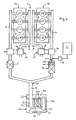
- 1 denotes an internal combustion engine which serves, for example, as a drive source of a vehicle.
- this internal combustion engine 1 is a 6-cylinder in-line engine whose cylinders are designated C1, C2, C3, C4, C5, C6.
- the internal combustion engine 1 is formed by an 8-cylinder V-engine whose cylinder with C1 ', C2', C3 ', C4', C5 ', C6', C7 'and C8' and its two rows of cylinders with 1a, 1b are designated.
- the exhaust gas outlets of the cylinders are designated 2.
- the exhaust gas outlets 2 of a part of the cylinders (C1, C2, C3 in Fig.
- the catalyst 7 arranged in an exhaust partial section 3 is formed by an oxidation catalytic converter with which the nitrogen monoxide (NO) contained in the exhaust gas flowing through is immutable in nitrogen dioxide (NO 2 ).
- the catalyst 8 arranged in the other exhaust sub-strand 4 is formed by a hydrolysis catalytic converter, and in this exhaust sub-branch 4, upstream of the hydrolysis catalytic converter 8, is a reducing agent einüsbar, via a nozzle 11, which is supplied from a reservoir 12 forth via a metering device 13, the reducing agent in the required amount. From this reducing agent 8 ammonia can be generated with the aid of the hydrolysis catalyst.
- the hydrolysis catalytic converter 8 can be preceded by a flow mixer 14 and optionally also an evaporator or a heating device 15.
- the flow mixer 14 is used for intimate mixing of the injected reducing agent with the exhaust gas and to even out the distribution of this mixture over the entire inlet cross section of the hydrolysis catalyst 8.
- the evaporator or the heater 15 are used to accelerate the evaporation of the injected reducing agent.
- each of the exhaust partial strands 3, 4 flows upstream of the respective catalytic converter 7, 8 via the turbine 16 of an exhaust gas turbocharger 17, through the compressor 18 of which the charge air duct 5 can be supplied with charge air.
- the at least one further catalytic converter 10 in the main exhaust line 9 is one or more SCR catalyst (s) and optionally ammonia (NH 3 ) peroxidation catalyst (s) 10a, particle oxidation catalyst (s) 10b, and nitrogen dioxide (NO 2 ). Barrier catalyst (s) 10c.
- these catalysts 10, 10a, 10b, 10c are arranged in series one behind the other in the exhaust gas line 9.
- a muffler 19 is provided in the main exhaust line 9, in which the or the catalyst (s) 10, 10 a, 10 b, 10 c are installed.
- That section of the exhaust main line 9 between the junction 20 of the two exhaust partial strands 3, 4 and the entry point into the (first) catalyst (s) 10 forms a sufficiently long mixing section for the two different, introduced from the exhaust gas strands 3, 4 in the main exhaust line 9 gas streams.
- a pipe section 9 'of the main exhaust pipe 9 is part of this mixing section, which is extended far into the interior of the muffler 19 and discharges into an inlet space 21 given at the rear.
- the inflow space 21 is separated from a front outflow space 23 by a wall 22.
Abstract
Description
Die Erfindung betrifft eine mehrzylindrige Brennkraftmaschine mit Merkmalen der im Oberbegriff des Anspruchs 1 angegebenen Art.The invention relates to a multi-cylinder internal combustion engine with features specified in the preamble of claim 1 Art.
Die Erfindung geht aus von der
Es ist daher Aufgabe der Erfindung, einer Brennkraftmaschine der gattungsgemäßen Art eine Abgasnachbehandlungsvorrichtung zuzuordnen, bei der aufgrund der Auswahl und Anordnung der Katalysatoren jene Probleme, wie sie bei der Parallelanordnung der Katalysatoren im Vorschalldämpfer der
Diese Aufgabe wird erfindungsgemäß durch die im Anspruch 1 angegebenen kennzeichnenden Merkmale gelöst.This object is achieved by the characterizing features specified in claim 1.
Vorteilhafte Ausgestaltungen und Weiterbildungen der erfindungsgemäßen Lösung sind in den Unteransprüchen angegeben.Advantageous embodiments and further developments of the solution according to the invention are specified in the subclaims.
Aufgrund der erfindungsgemäßen Anordnung des Oxidationskatalysators und Hydrolysekatalysators in jeweils einem eigenen Abgasteilstrang ist jeder dieser Katalysatoren immer mit einem definierten Abgasstrom beaufschlagt. Die Funktionalitäten der beiden Katalysatoren werden aufgrund ihrer getrennten Anordnung nicht gegenseitig beeinflusst, sondern kommen voll zur Wirkung. Das heißt, über den Oxidationskatalysator strömt ein definierter Abgasstrom, in dem das NO in definierter Menge zu NO2 umgewandelt wird. Dem Hydrolysekatalysator ist eine definierte, durch das Rohr des Abgasteilstrangs gegebene Eindüsstrecke für das Reduktionsmittel zugeordnet. Nach den Katalysatoren werden die beiden dann unterschiedlichen Gasströme zusammengeführt, anschließend im Abgashauptstrang in einer hinreichend langen Mischstrecke innig vermischt und dann durch den bzw. die SCR-Katalysatoren sowie gegebenenfalls weitere Katalysatoren geleitet.Due to the inventive arrangement of the oxidation catalyst and the hydrolysis in each case a separate exhaust manifold, each of these catalysts is always subjected to a defined exhaust gas flow. The functionalities of the two catalysts are not mutually influenced due to their separate arrangement, but come fully to effect. That is, via the oxidation catalyst flows a defined exhaust gas flow, in which the NO is converted in a defined amount to NO 2 . The hydrolysis catalyst is a defined, given by the pipe of the exhaust pipe section Eindüsstrecke for associated with the reducing agent. After the catalysts, the two then different gas streams are combined, then intimately mixed in the main exhaust line in a sufficiently long mixing section and then passed through the SCR catalysts and optionally further catalysts.
Nachfolgend ist die erfindungsgemäße Lösung anhand zweier in der Zeichnung dargestellter Ausführungsbeispiele noch näher erläutert. In der Zeichnung zeigen:
- Fig. 1
- schematisch als mehrzylindrige Brennkraftmaschine einen 6-Zylinder-Reihenmotor und
- Fig. 2
- schematisch als mehrzylindrige Brennkraftmaschine einen 8-Zylinder-Reihenmotor, jeweils mit einer erfindungsgemäßen Abgasstrang- und Katalysatoranordnung.
- Fig. 1
- schematically a multi-cylinder internal combustion engine, a 6-cylinder inline engine and
- Fig. 2
- schematically as a multi-cylinder internal combustion engine, an 8-cylinder in-line engine, each with an exhaust gas and catalyst arrangement according to the invention.
In den Figuren ist mit 1 eine Brennkraftmaschine bezeichnet, die beispielsweise als Antriebsquelle eines Fahrzeugs dient. In Fig. 1 ist diese Brennkraftmaschine 1 ein 6-Zylinder-Reihenmotor, dessen Zylinder mit C1, C2, C3, C4, C5, C6 bezeichnet sind. In Fig. 2 ist die Brennkraftmaschine 1 durch einen 8-Zylinder-V-Motor gebildet, dessen Zylinder mit C1', C2', C3', C4', C5', C6', C7' und C8' und dessen beide Zylinderreihen mit 1a, 1b bezeichnet sind. Die Abgasauslässe der Zylinder sind mit 2 bezeichnet. Bei jeder Brennkraftmaschine 1 sind die Abgasauslässe 2 eines Teils der Zylinder (C1, C2, C3 in Fig. 1; C1', C2', C3', C4' in Fig. 2) an einem ersten Abgasteilstrang 3 und die Abgasauslässe 2 der restlichen Zylinder (C4, C5, C6 in Fig. 1; C5', C6', C7', C8' in Fig. 2) an einem zweiten Abgasteilstrang 4 angeschlossen. Mit 5 ist eine Ausgang- oder Ladeluftleitung bezeichnet, aus der die Zylinder der Brennkraftmaschine 1 über Einlässe 6 mit Verbrennungsluft bzw. Ladeluft versorgbar sind. In jeden der beiden Abgasteilstränge 3, 4 ist ein Katalysator 7 bzw. 8 angeordnet. Strömungsmäßig nach diesen Katalysatoren 7, 8 münden die beiden Abgasteilstränge 3, 4 in einen dann gemeinsamen Abgashauptstrang 9 ein, in dem wenigstens ein weiterer Katalysator 10 angeordnet ist.In the figures, 1 denotes an internal combustion engine which serves, for example, as a drive source of a vehicle. In Fig. 1, this internal combustion engine 1 is a 6-cylinder in-line engine whose cylinders are designated C1, C2, C3, C4, C5, C6. In Fig. 2, the internal combustion engine 1 is formed by an 8-cylinder V-engine whose cylinder with C1 ', C2', C3 ', C4', C5 ', C6', C7 'and C8' and its two rows of cylinders with 1a, 1b are designated. The exhaust gas outlets of the cylinders are designated 2. In each internal combustion engine 1, the exhaust gas outlets 2 of a part of the cylinders (C1, C2, C3 in Fig. 1, C1 ', C2', C3 ', C4' in Fig. 2) on a first
Erfindungsgemäß ist der im einen Abgasteilstrang 3 angeordnete Katalysator 7 durch einen Oxidationskatalysator gebildet, mit dem das im durchströmenden Abgas enthaltene Stickstoffmonoxid (NO) in Stickstoffdioxid (NO2) unwandelbar ist. Des Weiteren ist der im anderen Abgasteilstrang 4 angeordnete Katalysator 8 durch einen Hydrolysekatalysator gebildet und in diesen Abgasteilstrang 4 ist strömungsmäßig vor dem Hydrolysekatalysator 8 ein Reduktionsmittel eindüsbar, und zwar über eine Düse 11, die von einem Vorratsbehälter 12 her über eine Dosiereinrichtung 13 das Reduktionsmittel in erforderlicher Menge zugeführt bekommt. Aus diesem Reduktionsmittel ist unter Zuhilfenahme des Hydrolysekatalysators 8 Ammoniak erzeugbar.According to the invention, the
Dem Hydrolysekatalysator 8 kann dann, wenn es sich bei dem Reduktionsmittel um eine Harnstoffwasserlösung handelt, ein Strömungsmischer 14 und gegebenenfalls auch noch ein Verdampfer bzw. eine Heizeinrichtung 15 vorgeschaltet sein. Der Strömungsmischer 14 dient zur innigen Vermischung des eingedüsten Reduktionsmittels mit dem Abgas sowie zur Vergleichmäßigung der Verteilung dieses Gemisches über den ganzen Eintrittsquerschnitt des Hydrolysekatalysators 8. Der Verdampfer bzw. die Heizeinrichtung 15 dienen zur Beschleunigung der Verdampfung des eingedüsten Reduktionsmittels.When the reducing agent is a urea-water solution, the hydrolysis
Bei dem V-Motor gemäß Fig. 2 führt jeder der Abgasteilstränge 3, 4 strömungsmäßig vor dem jeweiligen Katalysator 7, 8 über die Turbine 16 eines Abgasturboladers 17, durch dessen Verdichter 18 die Ladeluftleitung 5 mit Ladeluft versorgbar ist.In the V-engine according to FIG. 2, each of the exhaust
Bei dem wenigstens einen weiteren Katalysator 10 im Abgashauptstrang 9 handelt es sich um einen oder mehrere SCR-Katalysator(en) und gegebenenfalls Ammoniak (NH3)-Sperroxidationskatalysator(en) 10a, Partikeloxidationskatalysator(en) 10b, sowie Stickstoffdioxid (NO2)-Sperrkatalysator(en) 10c.The at least one further
Im Beispiel von Fig. 1 sind diese Katalysatoren 10, 10a, 10b, 10c in Reihe hintereinander im Abgasstrang 9 angeordnet. lm Beispiel gemäß Fig. 2 dagegen ist im Abgashauptstrang 9 ein Schalldämpfer 19 vorgesehen, in den der bzw. die Katalysator(en) 10, 10a, 10b, 10c eingebaut sind.In the example of FIG. 1, these
Jener Abschnitt des Abgashauptstranges 9 zwischen der Vereinigungsstelle 20 der beiden Abgasteilstränge 3, 4 und der Eintrittsstelle in den (ersten der) Katalysator(en) 10 bildet eine hinreichend lange Mischstrecke für die beiden unterschiedlichen, aus den Abgasteilsträngen 3, 4 in den Abgashauptstrang 9 eingeleiteten Gasströme. Im Fall des Beispiels gemäß Fig. 2 ist ein Rohrstück 9' des Abgashauptstranges 9 Teil dieser Mischstrecke, das weit in den Innenraum des Schalldämpfers 19 hinein verlängert ist und in einen hinten gegebenen Einströmraum 21 ausmündet. Der Einströmraum 21 ist im tonnenförmigen Schalldämpfer 19 durch eine Wand 22 von einem vorderen Abströmraum 23 getrennt. Von dieser gasundurchlässigen Wand 22 und einer gasdurchlässigen Haltewand 24 sind parallel durchströmbare Katalysatormodule 10' im Schalldämpfer 19 lagefixiert. Jede dieser Katalysatormodule 10' weist in einem eigenen Gehäuse einen SCR-Katalysator 10 und strömungsmäßig anschlie-ßend einen Ammoniaksperrkatalysator 10a auf. Vom Abströmraum 23 führt ein Endrohr 9" aus dem Schalldämpfer 19 heraus, in das im dargestellten Fall ein Stickstoffdioxid (NO2)-Sperrkatalysator 10c eingebaut ist, gegebenenfalls auch noch ein Partikeloxidationskatalyssator 10b eingebaut sein kann.That section of the exhaust
Claims (7)
Applications Claiming Priority (1)
| Application Number | Priority Date | Filing Date | Title |
|---|---|---|---|
| AT0077406A AT503125B1 (en) | 2006-05-05 | 2006-05-05 | Multi-cylinder internal combustion engine mounted in commercial vehicle, has oxidation and hydrolysis catalytic converters that are placed in different exhaust gas manifold sections |
Publications (2)
| Publication Number | Publication Date |
|---|---|
| EP1852582A1 true EP1852582A1 (en) | 2007-11-07 |
| EP1852582B1 EP1852582B1 (en) | 2008-06-18 |
Family
ID=38006787
Family Applications (1)
| Application Number | Title | Priority Date | Filing Date |
|---|---|---|---|
| EP07007277A Active EP1852582B1 (en) | 2006-05-05 | 2007-04-07 | Multi-cylinder internal combustion engine having several catalysts in the exhaust gas system |
Country Status (4)
| Country | Link |
|---|---|
| US (1) | US8151561B2 (en) |
| EP (1) | EP1852582B1 (en) |
| AT (1) | AT503125B1 (en) |
| DE (1) | DE502007000022D1 (en) |
Cited By (5)
| Publication number | Priority date | Publication date | Assignee | Title |
|---|---|---|---|---|
| DE102008016177A1 (en) | 2008-03-28 | 2009-10-08 | Süd-Chemie AG | Harnstoffhydrolysekatalysator |
| FR2984406A1 (en) * | 2011-12-20 | 2013-06-21 | Peugeot Citroen Automobiles Sa | Exhaust line for thermal combustion engine of car, has exhaust branches joined in connection point to form gathered line, and depollution device eliminating pollutant in exhaust fumes by injection of depollution agent by injection module |
| WO2013093266A1 (en) * | 2011-12-20 | 2013-06-27 | Peugeot Citroen Automobiles Sa | Exhaust line for a multiple supercharged engine with single injection of a reducing agent and method for injecting a reducing agent for such a line |
| FR3037101A1 (en) * | 2015-06-08 | 2016-12-09 | Peugeot Citroen Automobiles Sa | EXHAUST LINE OF A THERMAL ENGINE |
| EP3130774A1 (en) * | 2015-08-10 | 2017-02-15 | Toyota Jidosha Kabushiki Kaisha | Exhaust gas purification system for internal combustion engine |
Families Citing this family (3)
| Publication number | Priority date | Publication date | Assignee | Title |
|---|---|---|---|---|
| DE102008035562A1 (en) * | 2008-07-30 | 2010-02-04 | Emitec Gesellschaft Für Emissionstechnologie Mbh | Emission control system for diesel engines of commercial vehicles |
| CA2893661C (en) * | 2012-12-21 | 2021-05-25 | Alzchem Ag | Ammonia gas generator and the use of thereof for reducing nitrogen oxides in exhaust gases |
| WO2018035434A1 (en) | 2016-08-19 | 2018-02-22 | Kohler Co. | System and method for low co emission engine |
Citations (6)
| Publication number | Priority date | Publication date | Assignee | Title |
|---|---|---|---|---|
| DE10020639A1 (en) * | 1999-05-19 | 2000-11-30 | Ford Global Tech Inc | Controlling temperature in e.g. catalyst or adsorber passing exhaust gases from engine with two or more cylinders, is achieved by supplying separate, differing fuel air mixtures to each cylinder |
| DE10123359A1 (en) * | 2001-05-14 | 2002-11-21 | Man Nutzfahrzeuge Ag | Exhaust gas pipe used for a diesel engine of a commercial vehicle comprises a main silencer delimited by a front wall, a rear wall and a peripheral wall and divided into an inlet chamber and an outlet chamber |
| DE10218255A1 (en) * | 2002-04-24 | 2003-11-20 | Eberspaecher J Gmbh & Co | Exhaust system for a diesel engine and associated silencer |
| DE10322963A1 (en) * | 2002-06-04 | 2003-12-24 | Ford Global Tech Inc | Process for rapid catalyst heating |
| GB2389918A (en) * | 2002-06-21 | 2003-12-24 | Lotus Car | De-activation of combustion chambers in a multi-combustion chamber i.c. engine |
| EP1422410A2 (en) * | 2002-11-22 | 2004-05-26 | Robert Bosch Gmbh | Method for operating a multi-cylinder internal combustion engine with NOx-catalyst |
Family Cites Families (9)
| Publication number | Priority date | Publication date | Assignee | Title |
|---|---|---|---|---|
| DE4038054A1 (en) * | 1990-11-29 | 1992-06-04 | Man Technologie Gmbh | METHOD AND DEVICE FOR SELECTIVE CATALYTIC NO (DOWN ARROW) X (DOWN ARROW) REDUCTION IN OXYGEN-BASED EXHAUST GASES |
| DE4203807A1 (en) * | 1990-11-29 | 1993-08-12 | Man Nutzfahrzeuge Ag | Catalytic nitrogen oxide(s) redn. appts. for vehicles - comprises flow mixer urea evaporator hydrolysis catalyst, for exhaust gas treatment |
| DE10206028A1 (en) * | 2002-02-14 | 2003-08-28 | Man Nutzfahrzeuge Ag | Process and apparatus for producing ammonia |
| US7065958B2 (en) * | 2002-05-07 | 2006-06-27 | Extengine Transport Systems | Emission control system |
| US7552583B2 (en) * | 2004-11-08 | 2009-06-30 | Caterpillar Inc. | Exhaust purification with on-board ammonia production |
| DE10308287B4 (en) * | 2003-02-26 | 2006-11-30 | Umicore Ag & Co. Kg | Process for exhaust gas purification |
| JP2005226528A (en) * | 2004-02-12 | 2005-08-25 | Tokyo Roki Co Ltd | Scr muffler |
| US7776280B2 (en) * | 2005-05-10 | 2010-08-17 | Emcon Technologies Llc | Method and apparatus for selective catalytic reduction of NOx |
| US7607291B2 (en) * | 2005-10-03 | 2009-10-27 | Caterpillar Inc. | Engine system arrangement with on-board ammonia production and exhaust after treatment system |
-
2006
- 2006-05-05 AT AT0077406A patent/AT503125B1/en active
-
2007
- 2007-04-07 DE DE502007000022T patent/DE502007000022D1/en active Active
- 2007-04-07 EP EP07007277A patent/EP1852582B1/en active Active
- 2007-05-04 US US11/744,366 patent/US8151561B2/en active Active
Patent Citations (6)
| Publication number | Priority date | Publication date | Assignee | Title |
|---|---|---|---|---|
| DE10020639A1 (en) * | 1999-05-19 | 2000-11-30 | Ford Global Tech Inc | Controlling temperature in e.g. catalyst or adsorber passing exhaust gases from engine with two or more cylinders, is achieved by supplying separate, differing fuel air mixtures to each cylinder |
| DE10123359A1 (en) * | 2001-05-14 | 2002-11-21 | Man Nutzfahrzeuge Ag | Exhaust gas pipe used for a diesel engine of a commercial vehicle comprises a main silencer delimited by a front wall, a rear wall and a peripheral wall and divided into an inlet chamber and an outlet chamber |
| DE10218255A1 (en) * | 2002-04-24 | 2003-11-20 | Eberspaecher J Gmbh & Co | Exhaust system for a diesel engine and associated silencer |
| DE10322963A1 (en) * | 2002-06-04 | 2003-12-24 | Ford Global Tech Inc | Process for rapid catalyst heating |
| GB2389918A (en) * | 2002-06-21 | 2003-12-24 | Lotus Car | De-activation of combustion chambers in a multi-combustion chamber i.c. engine |
| EP1422410A2 (en) * | 2002-11-22 | 2004-05-26 | Robert Bosch Gmbh | Method for operating a multi-cylinder internal combustion engine with NOx-catalyst |
Cited By (5)
| Publication number | Priority date | Publication date | Assignee | Title |
|---|---|---|---|---|
| DE102008016177A1 (en) | 2008-03-28 | 2009-10-08 | Süd-Chemie AG | Harnstoffhydrolysekatalysator |
| FR2984406A1 (en) * | 2011-12-20 | 2013-06-21 | Peugeot Citroen Automobiles Sa | Exhaust line for thermal combustion engine of car, has exhaust branches joined in connection point to form gathered line, and depollution device eliminating pollutant in exhaust fumes by injection of depollution agent by injection module |
| WO2013093266A1 (en) * | 2011-12-20 | 2013-06-27 | Peugeot Citroen Automobiles Sa | Exhaust line for a multiple supercharged engine with single injection of a reducing agent and method for injecting a reducing agent for such a line |
| FR3037101A1 (en) * | 2015-06-08 | 2016-12-09 | Peugeot Citroen Automobiles Sa | EXHAUST LINE OF A THERMAL ENGINE |
| EP3130774A1 (en) * | 2015-08-10 | 2017-02-15 | Toyota Jidosha Kabushiki Kaisha | Exhaust gas purification system for internal combustion engine |
Also Published As
| Publication number | Publication date |
|---|---|
| AT503125B1 (en) | 2007-08-15 |
| DE502007000022D1 (en) | 2008-07-31 |
| AT503125A4 (en) | 2007-08-15 |
| US20070261393A1 (en) | 2007-11-15 |
| EP1852582B1 (en) | 2008-06-18 |
| US8151561B2 (en) | 2012-04-10 |
Similar Documents
| Publication | Publication Date | Title |
|---|---|---|
| AT503125B1 (en) | Multi-cylinder internal combustion engine mounted in commercial vehicle, has oxidation and hydrolysis catalytic converters that are placed in different exhaust gas manifold sections | |
| EP2325452B1 (en) | Device for treating exhaust gases of internal combustion engines | |
| DE102008042767B4 (en) | emission control system | |
| EP3149298B1 (en) | Exhaust gas post treatment system and method for exhaust gas post-treatment | |
| EP2161423B1 (en) | Exhaust gas facility for diesel vehicles with an SCR catalytic converter | |
| EP2574750B1 (en) | Mixing and/or evaporating device | |
| EP1857651A2 (en) | Exhaust gas treating device for an internal combustion engine | |
| EP2101049A2 (en) | Compact exhaust gas after treatment system | |
| DE102006038290A1 (en) | Exhaust gas after treatment system with nitrogen oxide and particle reduction during operation of internal combustion engine such as diesel engine, has oxidation catalyst arranged in part of exhaust gas stream and particle separator | |
| EP1900916A2 (en) | Exhaust gas finishing treatment system | |
| WO2013010700A1 (en) | Arrangement for introducing an additive into a gas flow | |
| EP2280155A2 (en) | Method and device for cleaning an exhaust gas flow of an exhaust gas turbocharged combustion engine | |
| DE10218255A1 (en) | Exhaust system for a diesel engine and associated silencer | |
| DE102020127384A1 (en) | SAMPLING DEVICE FOR AN EXHAUST GAS SENSOR | |
| EP2610457A1 (en) | Exhaust gas treatment device | |
| EP2280154A2 (en) | Method and device for cleaning an exhaust gas flow of a combustion engine | |
| EP1852583B1 (en) | Exhaust assembly of a combustion engine with several catalytic converters in the exhaust tract | |
| EP2171231B1 (en) | Device for the purification of exhaust gases of an internal combustion engine | |
| DE102008048428A1 (en) | Apparatus and method for purifying an exhaust gas stream of an internal combustion engine, in particular a lean-running internal combustion engine | |
| EP1510674B1 (en) | Exhaust gas system of an internal combustion engine with integrated pre- and main- silencer | |
| DE102008022998B4 (en) | Apparatus and method for purifying exhaust gases for an exhaust line of an internal combustion engine | |
| EP3388646B1 (en) | Exhaust gas purification system for an internal combustion engine as well as an internal combustion engine | |
| DE102020101074A1 (en) | Cooling system for a reducing agent metering system and an internal combustion engine with such a cooling system | |
| DE102005041733A1 (en) | Exhaust gas after treatment device for e.g. diesel engine, has treatment section arranged between fluid injection unit and silencer in common housing and comprising baffle for exhaust gas mass flow with fluid, e.g. urea water solution | |
| EP2573340B1 (en) | Exhaust gas device for a combustion engine |
Legal Events
| Date | Code | Title | Description |
|---|---|---|---|
| PUAI | Public reference made under article 153(3) epc to a published international application that has entered the european phase |
Free format text: ORIGINAL CODE: 0009012 |
|
| 17P | Request for examination filed |
Effective date: 20070727 |
|
| AK | Designated contracting states |
Kind code of ref document: A1 Designated state(s): AT BE BG CH CY CZ DE DK EE ES FI FR GB GR HU IE IS IT LI LT LU LV MC MT NL PL PT RO SE SI SK TR |
|
| AX | Request for extension of the european patent |
Extension state: AL BA HR MK YU |
|
| 17Q | First examination report despatched |
Effective date: 20071220 |
|
| GRAP | Despatch of communication of intention to grant a patent |
Free format text: ORIGINAL CODE: EPIDOSNIGR1 |
|
| GRAS | Grant fee paid |
Free format text: ORIGINAL CODE: EPIDOSNIGR3 |
|
| GRAA | (expected) grant |
Free format text: ORIGINAL CODE: 0009210 |
|
| AK | Designated contracting states |
Kind code of ref document: B1 Designated state(s): DE FR IT NL SE |
|
| AKX | Designation fees paid |
Designated state(s): DE FR IT NL SE |
|
| REF | Corresponds to: |
Ref document number: 502007000022 Country of ref document: DE Date of ref document: 20080731 Kind code of ref document: P |
|
| REG | Reference to a national code |
Ref country code: SE Ref legal event code: TRGR |
|
| PLBE | No opposition filed within time limit |
Free format text: ORIGINAL CODE: 0009261 |
|
| STAA | Information on the status of an ep patent application or granted ep patent |
Free format text: STATUS: NO OPPOSITION FILED WITHIN TIME LIMIT |
|
| 26N | No opposition filed |
Effective date: 20090319 |
|
| PG25 | Lapsed in a contracting state [announced via postgrant information from national office to epo] |
Ref country code: IT Free format text: LAPSE BECAUSE OF NON-PAYMENT OF DUE FEES Effective date: 20100407 |
|
| REG | Reference to a national code |
Ref country code: NL Ref legal event code: TD Effective date: 20120223 |
|
| REG | Reference to a national code |
Ref country code: DE Ref legal event code: R081 Ref document number: 502007000022 Country of ref document: DE Owner name: MAN TRUCK & BUS OESTERREICH AG, AT Free format text: FORMER OWNER: MAN NUTZFAHRZEUGE OESTERREICH AG, STEYR, AT Effective date: 20120125 |
|
| REG | Reference to a national code |
Ref country code: FR Ref legal event code: CD Owner name: MAN TRUCK & BUS OSTERREICH AG Effective date: 20120314 |
|
| REG | Reference to a national code |
Ref country code: FR Ref legal event code: PLFP Year of fee payment: 10 |
|
| REG | Reference to a national code |
Ref country code: FR Ref legal event code: PLFP Year of fee payment: 11 |
|
| REG | Reference to a national code |
Ref country code: FR Ref legal event code: PLFP Year of fee payment: 12 |
|
| REG | Reference to a national code |
Ref country code: DE Ref legal event code: R081 Ref document number: 502007000022 Country of ref document: DE Owner name: MAN TRUCK & BUS SE, DE Free format text: FORMER OWNER: MAN TRUCK & BUS OESTERREICH AG, STEYR, AT |
|
| PGFP | Annual fee paid to national office [announced via postgrant information from national office to epo] |
Ref country code: SE Payment date: 20230317 Year of fee payment: 17 |
|
| PGFP | Annual fee paid to national office [announced via postgrant information from national office to epo] |
Ref country code: NL Payment date: 20230424 Year of fee payment: 17 |
|
| PGFP | Annual fee paid to national office [announced via postgrant information from national office to epo] |
Ref country code: IT Payment date: 20230421 Year of fee payment: 17 Ref country code: FR Payment date: 20230421 Year of fee payment: 17 Ref country code: DE Payment date: 20230427 Year of fee payment: 17 |
|
| REG | Reference to a national code |
Ref country code: NL Ref legal event code: PD Owner name: MAN TRUCK & BUS OESTERREICH GESMBH; AT Free format text: DETAILS ASSIGNMENT: CHANGE OF OWNER(S), ASSIGNMENT; FORMER OWNER NAME: MAN TRUCK & BUS OESTERREICH GESMBH Effective date: 20231031 |