EP1852576A2 - Procédé de récupération, d' emmagasinage et de préparation d' agents de travail, procédé d' utilisation d' agents de travail avec un moteur à piston oscillant - Google Patents
Procédé de récupération, d' emmagasinage et de préparation d' agents de travail, procédé d' utilisation d' agents de travail avec un moteur à piston oscillant Download PDFInfo
- Publication number
- EP1852576A2 EP1852576A2 EP07009041A EP07009041A EP1852576A2 EP 1852576 A2 EP1852576 A2 EP 1852576A2 EP 07009041 A EP07009041 A EP 07009041A EP 07009041 A EP07009041 A EP 07009041A EP 1852576 A2 EP1852576 A2 EP 1852576A2
- Authority
- EP
- European Patent Office
- Prior art keywords
- piston
- working
- pressure
- working fluid
- rotary
- Prior art date
- Legal status (The legal status is an assumption and is not a legal conclusion. Google has not performed a legal analysis and makes no representation as to the accuracy of the status listed.)
- Withdrawn
Links
- 238000000034 method Methods 0.000 title claims description 74
- 230000008569 process Effects 0.000 title claims description 42
- CURLTUGMZLYLDI-UHFFFAOYSA-N Carbon dioxide Chemical compound O=C=O CURLTUGMZLYLDI-UHFFFAOYSA-N 0.000 claims abstract description 78
- 239000007789 gas Substances 0.000 claims abstract description 70
- IJGRMHOSHXDMSA-UHFFFAOYSA-N Atomic nitrogen Chemical compound N#N IJGRMHOSHXDMSA-UHFFFAOYSA-N 0.000 claims abstract description 56
- 238000003860 storage Methods 0.000 claims abstract description 35
- 239000007788 liquid Substances 0.000 claims abstract description 34
- 229910002092 carbon dioxide Inorganic materials 0.000 claims abstract description 33
- 239000001569 carbon dioxide Substances 0.000 claims abstract description 33
- 238000001816 cooling Methods 0.000 claims abstract description 15
- 238000011084 recovery Methods 0.000 claims abstract description 10
- JCXJVPUVTGWSNB-UHFFFAOYSA-N nitrogen dioxide Inorganic materials O=[N]=O JCXJVPUVTGWSNB-UHFFFAOYSA-N 0.000 claims abstract description 8
- 238000000926 separation method Methods 0.000 claims abstract description 4
- 239000012530 fluid Substances 0.000 claims description 118
- 238000002485 combustion reaction Methods 0.000 claims description 29
- 239000003570 air Substances 0.000 claims description 28
- 239000000463 material Substances 0.000 claims description 26
- 239000000446 fuel Substances 0.000 claims description 24
- 229910052757 nitrogen Inorganic materials 0.000 claims description 24
- 239000011148 porous material Substances 0.000 claims description 24
- XLYOFNOQVPJJNP-UHFFFAOYSA-N water Substances O XLYOFNOQVPJJNP-UHFFFAOYSA-N 0.000 claims description 24
- 229910001868 water Inorganic materials 0.000 claims description 21
- 238000007906 compression Methods 0.000 claims description 20
- 230000001105 regulatory effect Effects 0.000 claims description 20
- 230000006835 compression Effects 0.000 claims description 19
- 239000000203 mixture Substances 0.000 claims description 13
- 238000010438 heat treatment Methods 0.000 claims description 10
- 239000007787 solid Substances 0.000 claims description 10
- 235000011089 carbon dioxide Nutrition 0.000 claims description 9
- 230000033001 locomotion Effects 0.000 claims description 9
- 230000005611 electricity Effects 0.000 claims description 8
- 239000003344 environmental pollutant Substances 0.000 claims description 8
- VNWKTOKETHGBQD-UHFFFAOYSA-N methane Chemical compound C VNWKTOKETHGBQD-UHFFFAOYSA-N 0.000 claims description 8
- 230000003647 oxidation Effects 0.000 claims description 8
- 238000007254 oxidation reaction Methods 0.000 claims description 8
- 231100000719 pollutant Toxicity 0.000 claims description 8
- 239000002918 waste heat Substances 0.000 claims description 8
- 239000002028 Biomass Substances 0.000 claims description 7
- QVGXLLKOCUKJST-UHFFFAOYSA-N atomic oxygen Chemical compound [O] QVGXLLKOCUKJST-UHFFFAOYSA-N 0.000 claims description 7
- 239000006260 foam Substances 0.000 claims description 7
- 239000001301 oxygen Substances 0.000 claims description 7
- 229910052760 oxygen Inorganic materials 0.000 claims description 7
- 239000000919 ceramic Substances 0.000 claims description 6
- 230000008859 change Effects 0.000 claims description 6
- 239000005431 greenhouse gas Substances 0.000 claims description 6
- 239000000696 magnetic material Substances 0.000 claims description 6
- 239000008207 working material Substances 0.000 claims description 6
- 230000000694 effects Effects 0.000 claims description 5
- 230000007613 environmental effect Effects 0.000 claims description 5
- 229930195733 hydrocarbon Natural products 0.000 claims description 5
- 150000002430 hydrocarbons Chemical class 0.000 claims description 5
- 239000004033 plastic Substances 0.000 claims description 5
- 229920003023 plastic Polymers 0.000 claims description 5
- 230000001172 regenerating effect Effects 0.000 claims description 5
- QGZKDVFQNNGYKY-UHFFFAOYSA-N Ammonia Chemical compound N QGZKDVFQNNGYKY-UHFFFAOYSA-N 0.000 claims description 4
- 229920000049 Carbon (fiber) Polymers 0.000 claims description 4
- 239000004917 carbon fiber Substances 0.000 claims description 4
- 125000004122 cyclic group Chemical group 0.000 claims description 4
- 238000006073 displacement reaction Methods 0.000 claims description 4
- 239000003507 refrigerant Substances 0.000 claims description 4
- 239000011800 void material Substances 0.000 claims description 4
- 238000005299 abrasion Methods 0.000 claims description 3
- 150000001298 alcohols Chemical class 0.000 claims description 3
- 239000003365 glass fiber Substances 0.000 claims description 3
- 238000005057 refrigeration Methods 0.000 claims description 3
- 238000007789 sealing Methods 0.000 claims description 3
- 229910021529 ammonia Inorganic materials 0.000 claims description 2
- 230000000295 complement effect Effects 0.000 claims description 2
- 238000009826 distribution Methods 0.000 claims description 2
- 239000013013 elastic material Substances 0.000 claims description 2
- 230000002349 favourable effect Effects 0.000 claims description 2
- 230000007246 mechanism Effects 0.000 claims description 2
- 230000003584 silencer Effects 0.000 claims 3
- 238000003780 insertion Methods 0.000 claims 2
- 230000037431 insertion Effects 0.000 claims 2
- 239000000356 contaminant Substances 0.000 claims 1
- 239000000498 cooling water Substances 0.000 claims 1
- 238000000151 deposition Methods 0.000 claims 1
- 238000011010 flushing procedure Methods 0.000 claims 1
- 239000001307 helium Substances 0.000 claims 1
- 229910052734 helium Inorganic materials 0.000 claims 1
- SWQJXJOGLNCZEY-UHFFFAOYSA-N helium atom Chemical compound [He] SWQJXJOGLNCZEY-UHFFFAOYSA-N 0.000 claims 1
- 238000003801 milling Methods 0.000 claims 1
- 230000000704 physical effect Effects 0.000 claims 1
- 238000005381 potential energy Methods 0.000 claims 1
- 238000010926 purge Methods 0.000 claims 1
- 230000003134 recirculating effect Effects 0.000 claims 1
- 230000035939 shock Effects 0.000 claims 1
- 230000008646 thermal stress Effects 0.000 claims 1
- 230000007704 transition Effects 0.000 claims 1
- 238000011282 treatment Methods 0.000 claims 1
- 239000006200 vaporizer Substances 0.000 claims 1
- 239000000126 substance Substances 0.000 abstract description 5
- 230000015556 catabolic process Effects 0.000 abstract 1
- 238000005516 engineering process Methods 0.000 description 12
- 230000008901 benefit Effects 0.000 description 7
- 238000006243 chemical reaction Methods 0.000 description 6
- 239000001257 hydrogen Substances 0.000 description 6
- 229910052739 hydrogen Inorganic materials 0.000 description 6
- MWUXSHHQAYIFBG-UHFFFAOYSA-N nitrogen oxide Inorganic materials O=[N] MWUXSHHQAYIFBG-UHFFFAOYSA-N 0.000 description 6
- 241000196324 Embryophyta Species 0.000 description 5
- 230000005540 biological transmission Effects 0.000 description 5
- 238000005056 compaction Methods 0.000 description 5
- UFHFLCQGNIYNRP-UHFFFAOYSA-N Hydrogen Chemical compound [H][H] UFHFLCQGNIYNRP-UHFFFAOYSA-N 0.000 description 4
- 230000033228 biological regulation Effects 0.000 description 4
- 238000004146 energy storage Methods 0.000 description 4
- 238000004519 manufacturing process Methods 0.000 description 4
- 230000009467 reduction Effects 0.000 description 4
- OKKJLVBELUTLKV-UHFFFAOYSA-N Methanol Chemical compound OC OKKJLVBELUTLKV-UHFFFAOYSA-N 0.000 description 3
- 239000000443 aerosol Substances 0.000 description 3
- 229910052799 carbon Inorganic materials 0.000 description 3
- 239000000567 combustion gas Substances 0.000 description 3
- 230000006378 damage Effects 0.000 description 3
- 239000003502 gasoline Substances 0.000 description 3
- -1 hard Substances 0.000 description 3
- 239000008236 heating water Substances 0.000 description 3
- 229910001092 metal group alloy Inorganic materials 0.000 description 3
- 239000003345 natural gas Substances 0.000 description 3
- 239000011555 saturated liquid Substances 0.000 description 3
- OKTJSMMVPCPJKN-UHFFFAOYSA-N Carbon Chemical compound [C] OKTJSMMVPCPJKN-UHFFFAOYSA-N 0.000 description 2
- UGFAIRIUMAVXCW-UHFFFAOYSA-N Carbon monoxide Chemical compound [O+]#[C-] UGFAIRIUMAVXCW-UHFFFAOYSA-N 0.000 description 2
- LFQSCWFLJHTTHZ-UHFFFAOYSA-N Ethanol Chemical compound CCO LFQSCWFLJHTTHZ-UHFFFAOYSA-N 0.000 description 2
- LYCAIKOWRPUZTN-UHFFFAOYSA-N Ethylene glycol Chemical compound OCCO LYCAIKOWRPUZTN-UHFFFAOYSA-N 0.000 description 2
- XEEYBQQBJWHFJM-UHFFFAOYSA-N Iron Chemical compound [Fe] XEEYBQQBJWHFJM-UHFFFAOYSA-N 0.000 description 2
- RAHZWNYVWXNFOC-UHFFFAOYSA-N Sulphur dioxide Chemical compound O=S=O RAHZWNYVWXNFOC-UHFFFAOYSA-N 0.000 description 2
- 238000004378 air conditioning Methods 0.000 description 2
- 239000012080 ambient air Substances 0.000 description 2
- 150000001555 benzenes Chemical class 0.000 description 2
- 239000003225 biodiesel Substances 0.000 description 2
- 229910002091 carbon monoxide Inorganic materials 0.000 description 2
- 239000003054 catalyst Substances 0.000 description 2
- 238000001704 evaporation Methods 0.000 description 2
- 230000008020 evaporation Effects 0.000 description 2
- 229910002804 graphite Inorganic materials 0.000 description 2
- 239000010439 graphite Substances 0.000 description 2
- 150000002431 hydrogen Chemical class 0.000 description 2
- 238000012432 intermediate storage Methods 0.000 description 2
- 238000011068 loading method Methods 0.000 description 2
- 230000003472 neutralizing effect Effects 0.000 description 2
- 239000003921 oil Substances 0.000 description 2
- 235000019198 oils Nutrition 0.000 description 2
- 230000001590 oxidative effect Effects 0.000 description 2
- 239000008188 pellet Substances 0.000 description 2
- 238000010248 power generation Methods 0.000 description 2
- 238000000746 purification Methods 0.000 description 2
- 230000001846 repelling effect Effects 0.000 description 2
- 239000004071 soot Substances 0.000 description 2
- 239000010902 straw Substances 0.000 description 2
- 238000012546 transfer Methods 0.000 description 2
- 238000011144 upstream manufacturing Methods 0.000 description 2
- 239000002699 waste material Substances 0.000 description 2
- 239000002023 wood Substances 0.000 description 2
- 244000025254 Cannabis sativa Species 0.000 description 1
- RYGMFSIKBFXOCR-UHFFFAOYSA-N Copper Chemical compound [Cu] RYGMFSIKBFXOCR-UHFFFAOYSA-N 0.000 description 1
- MYMOFIZGZYHOMD-UHFFFAOYSA-N Dioxygen Chemical compound O=O MYMOFIZGZYHOMD-UHFFFAOYSA-N 0.000 description 1
- 244000021685 Mesembryanthemum crystallinum Species 0.000 description 1
- 239000004809 Teflon Substances 0.000 description 1
- 229920006362 Teflon® Polymers 0.000 description 1
- FNYLWPVRPXGIIP-UHFFFAOYSA-N Triamterene Chemical compound NC1=NC2=NC(N)=NC(N)=C2N=C1C1=CC=CC=C1 FNYLWPVRPXGIIP-UHFFFAOYSA-N 0.000 description 1
- 238000010521 absorption reaction Methods 0.000 description 1
- 230000009471 action Effects 0.000 description 1
- 230000006978 adaptation Effects 0.000 description 1
- 230000002411 adverse Effects 0.000 description 1
- 229910052782 aluminium Inorganic materials 0.000 description 1
- XAGFODPZIPBFFR-UHFFFAOYSA-N aluminium Chemical compound [Al] XAGFODPZIPBFFR-UHFFFAOYSA-N 0.000 description 1
- 230000003750 conditioning effect Effects 0.000 description 1
- 229910052802 copper Inorganic materials 0.000 description 1
- 239000010949 copper Substances 0.000 description 1
- 230000001419 dependent effect Effects 0.000 description 1
- 238000013461 design Methods 0.000 description 1
- 238000011161 development Methods 0.000 description 1
- 230000018109 developmental process Effects 0.000 description 1
- 238000007599 discharging Methods 0.000 description 1
- 238000003912 environmental pollution Methods 0.000 description 1
- 238000004880 explosion Methods 0.000 description 1
- 239000002360 explosive Substances 0.000 description 1
- 238000000605 extraction Methods 0.000 description 1
- 239000000945 filler Substances 0.000 description 1
- 238000001914 filtration Methods 0.000 description 1
- 238000010304 firing Methods 0.000 description 1
- 238000007667 floating Methods 0.000 description 1
- 239000002803 fossil fuel Substances 0.000 description 1
- 239000002737 fuel gas Substances 0.000 description 1
- 239000008187 granular material Substances 0.000 description 1
- 230000012010 growth Effects 0.000 description 1
- 239000000383 hazardous chemical Substances 0.000 description 1
- 230000036541 health Effects 0.000 description 1
- 239000003779 heat-resistant material Substances 0.000 description 1
- 239000010720 hydraulic oil Substances 0.000 description 1
- WGCNASOHLSPBMP-UHFFFAOYSA-N hydroxyacetaldehyde Natural products OCC=O WGCNASOHLSPBMP-UHFFFAOYSA-N 0.000 description 1
- 238000009434 installation Methods 0.000 description 1
- 229910052742 iron Inorganic materials 0.000 description 1
- 230000003137 locomotive effect Effects 0.000 description 1
- 230000007774 longterm Effects 0.000 description 1
- 229910052751 metal Inorganic materials 0.000 description 1
- 239000002184 metal Substances 0.000 description 1
- VUZPPFZMUPKLLV-UHFFFAOYSA-N methane;hydrate Chemical compound C.O VUZPPFZMUPKLLV-UHFFFAOYSA-N 0.000 description 1
- 238000002156 mixing Methods 0.000 description 1
- 238000005457 optimization Methods 0.000 description 1
- 238000013021 overheating Methods 0.000 description 1
- 239000002245 particle Substances 0.000 description 1
- 230000002093 peripheral effect Effects 0.000 description 1
- 238000012545 processing Methods 0.000 description 1
- 230000002035 prolonged effect Effects 0.000 description 1
- 230000035485 pulse pressure Effects 0.000 description 1
- 239000002994 raw material Substances 0.000 description 1
- 230000002441 reversible effect Effects 0.000 description 1
- HBMJWWWQQXIZIP-UHFFFAOYSA-N silicon carbide Chemical compound [Si+]#[C-] HBMJWWWQQXIZIP-UHFFFAOYSA-N 0.000 description 1
- 229910010271 silicon carbide Inorganic materials 0.000 description 1
- 239000007779 soft material Substances 0.000 description 1
- 210000002023 somite Anatomy 0.000 description 1
- 239000011232 storage material Substances 0.000 description 1
- 238000000859 sublimation Methods 0.000 description 1
- 230000008022 sublimation Effects 0.000 description 1
- 238000004381 surface treatment Methods 0.000 description 1
- 239000000725 suspension Substances 0.000 description 1
- 231100000331 toxic Toxicity 0.000 description 1
- 230000002588 toxic effect Effects 0.000 description 1
- 239000002341 toxic gas Substances 0.000 description 1
- 239000003053 toxin Substances 0.000 description 1
- 231100000765 toxin Toxicity 0.000 description 1
- 108700012359 toxins Proteins 0.000 description 1
- 238000009834 vaporization Methods 0.000 description 1
- 230000008016 vaporization Effects 0.000 description 1
- 235000015112 vegetable and seed oil Nutrition 0.000 description 1
- 239000008158 vegetable oil Substances 0.000 description 1
- 239000002912 waste gas Substances 0.000 description 1
Images






Classifications
-
- F—MECHANICAL ENGINEERING; LIGHTING; HEATING; WEAPONS; BLASTING
- F02—COMBUSTION ENGINES; HOT-GAS OR COMBUSTION-PRODUCT ENGINE PLANTS
- F02B—INTERNAL-COMBUSTION PISTON ENGINES; COMBUSTION ENGINES IN GENERAL
- F02B57/00—Internal-combustion aspects of rotary engines in which the combusted gases displace one or more reciprocating pistons
- F02B57/08—Engines with star-shaped cylinder arrangements
- F02B57/10—Engines with star-shaped cylinder arrangements with combustion space in centre of star
-
- F—MECHANICAL ENGINEERING; LIGHTING; HEATING; WEAPONS; BLASTING
- F01—MACHINES OR ENGINES IN GENERAL; ENGINE PLANTS IN GENERAL; STEAM ENGINES
- F01C—ROTARY-PISTON OR OSCILLATING-PISTON MACHINES OR ENGINES
- F01C1/00—Rotary-piston machines or engines
- F01C1/30—Rotary-piston machines or engines having the characteristics covered by two or more groups F01C1/02, F01C1/08, F01C1/22, F01C1/24 or having the characteristics covered by one of these groups together with some other type of movement between co-operating members
- F01C1/40—Rotary-piston machines or engines having the characteristics covered by two or more groups F01C1/02, F01C1/08, F01C1/22, F01C1/24 or having the characteristics covered by one of these groups together with some other type of movement between co-operating members having the movement defined in group F01C1/08 or F01C1/22 and having a hinged member
- F01C1/44—Rotary-piston machines or engines having the characteristics covered by two or more groups F01C1/02, F01C1/08, F01C1/22, F01C1/24 or having the characteristics covered by one of these groups together with some other type of movement between co-operating members having the movement defined in group F01C1/08 or F01C1/22 and having a hinged member with vanes hinged to the inner member
-
- F—MECHANICAL ENGINEERING; LIGHTING; HEATING; WEAPONS; BLASTING
- F01—MACHINES OR ENGINES IN GENERAL; ENGINE PLANTS IN GENERAL; STEAM ENGINES
- F01C—ROTARY-PISTON OR OSCILLATING-PISTON MACHINES OR ENGINES
- F01C11/00—Combinations of two or more machines or engines, each being of rotary-piston or oscillating-piston type
- F01C11/002—Combinations of two or more machines or engines, each being of rotary-piston or oscillating-piston type of similar working principle
-
- F—MECHANICAL ENGINEERING; LIGHTING; HEATING; WEAPONS; BLASTING
- F01—MACHINES OR ENGINES IN GENERAL; ENGINE PLANTS IN GENERAL; STEAM ENGINES
- F01C—ROTARY-PISTON OR OSCILLATING-PISTON MACHINES OR ENGINES
- F01C11/00—Combinations of two or more machines or engines, each being of rotary-piston or oscillating-piston type
- F01C11/006—Combinations of two or more machines or engines, each being of rotary-piston or oscillating-piston type of dissimilar working principle
- F01C11/008—Combinations of two or more machines or engines, each being of rotary-piston or oscillating-piston type of dissimilar working principle and of complementary function, e.g. internal combustion engine with supercharger
-
- F—MECHANICAL ENGINEERING; LIGHTING; HEATING; WEAPONS; BLASTING
- F01—MACHINES OR ENGINES IN GENERAL; ENGINE PLANTS IN GENERAL; STEAM ENGINES
- F01C—ROTARY-PISTON OR OSCILLATING-PISTON MACHINES OR ENGINES
- F01C19/00—Sealing arrangements in rotary-piston machines or engines
- F01C19/02—Radially-movable sealings for working fluids
-
- F—MECHANICAL ENGINEERING; LIGHTING; HEATING; WEAPONS; BLASTING
- F01—MACHINES OR ENGINES IN GENERAL; ENGINE PLANTS IN GENERAL; STEAM ENGINES
- F01C—ROTARY-PISTON OR OSCILLATING-PISTON MACHINES OR ENGINES
- F01C21/00—Component parts, details or accessories not provided for in groups F01C1/00 - F01C20/00
- F01C21/10—Outer members for co-operation with rotary pistons; Casings
- F01C21/104—Stators; Members defining the outer boundaries of the working chamber
- F01C21/106—Stators; Members defining the outer boundaries of the working chamber with a radial surface, e.g. cam rings
-
- F—MECHANICAL ENGINEERING; LIGHTING; HEATING; WEAPONS; BLASTING
- F01—MACHINES OR ENGINES IN GENERAL; ENGINE PLANTS IN GENERAL; STEAM ENGINES
- F01K—STEAM ENGINE PLANTS; STEAM ACCUMULATORS; ENGINE PLANTS NOT OTHERWISE PROVIDED FOR; ENGINES USING SPECIAL WORKING FLUIDS OR CYCLES
- F01K25/00—Plants or engines characterised by use of special working fluids, not otherwise provided for; Plants operating in closed cycles and not otherwise provided for
- F01K25/06—Plants or engines characterised by use of special working fluids, not otherwise provided for; Plants operating in closed cycles and not otherwise provided for using mixtures of different fluids
-
- F—MECHANICAL ENGINEERING; LIGHTING; HEATING; WEAPONS; BLASTING
- F01—MACHINES OR ENGINES IN GENERAL; ENGINE PLANTS IN GENERAL; STEAM ENGINES
- F01K—STEAM ENGINE PLANTS; STEAM ACCUMULATORS; ENGINE PLANTS NOT OTHERWISE PROVIDED FOR; ENGINES USING SPECIAL WORKING FLUIDS OR CYCLES
- F01K25/00—Plants or engines characterised by use of special working fluids, not otherwise provided for; Plants operating in closed cycles and not otherwise provided for
- F01K25/08—Plants or engines characterised by use of special working fluids, not otherwise provided for; Plants operating in closed cycles and not otherwise provided for using special vapours
- F01K25/10—Plants or engines characterised by use of special working fluids, not otherwise provided for; Plants operating in closed cycles and not otherwise provided for using special vapours the vapours being cold, e.g. ammonia, carbon dioxide, ether
-
- F—MECHANICAL ENGINEERING; LIGHTING; HEATING; WEAPONS; BLASTING
- F01—MACHINES OR ENGINES IN GENERAL; ENGINE PLANTS IN GENERAL; STEAM ENGINES
- F01K—STEAM ENGINE PLANTS; STEAM ACCUMULATORS; ENGINE PLANTS NOT OTHERWISE PROVIDED FOR; ENGINES USING SPECIAL WORKING FLUIDS OR CYCLES
- F01K25/00—Plants or engines characterised by use of special working fluids, not otherwise provided for; Plants operating in closed cycles and not otherwise provided for
- F01K25/08—Plants or engines characterised by use of special working fluids, not otherwise provided for; Plants operating in closed cycles and not otherwise provided for using special vapours
- F01K25/10—Plants or engines characterised by use of special working fluids, not otherwise provided for; Plants operating in closed cycles and not otherwise provided for using special vapours the vapours being cold, e.g. ammonia, carbon dioxide, ether
- F01K25/103—Carbon dioxide
-
- F—MECHANICAL ENGINEERING; LIGHTING; HEATING; WEAPONS; BLASTING
- F02—COMBUSTION ENGINES; HOT-GAS OR COMBUSTION-PRODUCT ENGINE PLANTS
- F02G—HOT GAS OR COMBUSTION-PRODUCT POSITIVE-DISPLACEMENT ENGINE PLANTS; USE OF WASTE HEAT OF COMBUSTION ENGINES; NOT OTHERWISE PROVIDED FOR
- F02G5/00—Profiting from waste heat of combustion engines, not otherwise provided for
- F02G5/02—Profiting from waste heat of exhaust gases
-
- Y—GENERAL TAGGING OF NEW TECHNOLOGICAL DEVELOPMENTS; GENERAL TAGGING OF CROSS-SECTIONAL TECHNOLOGIES SPANNING OVER SEVERAL SECTIONS OF THE IPC; TECHNICAL SUBJECTS COVERED BY FORMER USPC CROSS-REFERENCE ART COLLECTIONS [XRACs] AND DIGESTS
- Y02—TECHNOLOGIES OR APPLICATIONS FOR MITIGATION OR ADAPTATION AGAINST CLIMATE CHANGE
- Y02T—CLIMATE CHANGE MITIGATION TECHNOLOGIES RELATED TO TRANSPORTATION
- Y02T10/00—Road transport of goods or passengers
- Y02T10/10—Internal combustion engine [ICE] based vehicles
- Y02T10/12—Improving ICE efficiencies
Definitions
- the invention relates to a Rotationsschwenkkolbenmotor with double-acting piston, which produce a high level of torque on an inclined plane, a method for obtaining, storing and processing of the working means and a method for operating the Rotationsschwenkkolbenmotors in a partially closed cycle process.
- Rotationsschwenkkolbenmotore are known as internal combustion engines in particular for the operation of a hydrogen-oxyhydrogen gas mixture. From the publication DE 10319895 A1 a rotary swivel piston engine and its method of operation will be described.
- the disadvantages compared to the type mentioned above are:
- the swing pistons only work as torsionally swinging shut-off parts.
- the lower side, the radius surface of the thrust piston immersed in the rotor, the pivoting piston chamber, is pressed against the surfaces to be sealed and the inner wall of the housing only with the exhaust gas pressure, but friction pressure does not arise, which can act on the rotor shaft.
- the bearing over the swivel radii and Zentiwinkelspitzen lie in the hot working and pressure range, which is traversed three times in one revolution, which causes high stress for materials and all seals at a combustion temperature of about 1200 ° C.
- the swing pistons have for this Anlagenweg and the Relatively high swivel motion insufficient cooling, the materials must have dry-running properties.
- the bearing of the pistons in the rotor and the closed L-shape bring large pressure and flow losses with it.
- the torque is generated tangentially only from the front half of the arc surface and since it is a volume flow machine, the displacement is very large.
- Refrigeration power plants which are also called Organic Ranking Process (ORC) and work with refrigerant, have an effective efficiency of up to 12% when converted into mechanical energy because of the low temperature difference after the expansion machine. If you take inorganic Refrigerant such as ammonia, the efficiency increases to 15%. But only on the condition that the heat source provides a sufficient temperature difference of at least + 90 ° C to 120 ° C compared to the environmental temperature of + 15 ° C free of charge.
- the object of this invention is to provide a method for obtaining, storing and conditioning the working fluid, a method of operating a rotary rotary piston engine and a rotary rotary piston engine that efficiently converts the energy of the working fluid into mechanical kinetic energy and its structure is simple, its operation and application optimal for the generation of a torque is.
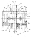
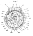
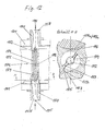
- the rotary swivel piston motor 50 which is designed in particular as a compressed gas engine for operation with various working means as mixed gas, essentially consists of a cylindrical housing 101, in which a cylindrical rotor 102 rotates, the rotor axis 103 is arranged eccentrically to the cylindrical housing 101. On the circumference of the rotor pivoting piston 104 are articulated at regular intervals. Motor housing 101 and rotor 102 form a crescent-shaped working space 105, in which swing the swing pistons. This crescent-shaped working space 105 is divided into two equal work spaces, the expansion space 106 and the compression space 107 of the working fluid.
- the rotor 102 is provided with recesses, referred to as inner swing piston chamber 108, into which the pistons swing in and out while being guided in the lower swing piston chamber 108.
- the upper, outer radial piston shape 109 is essentially determined by the motor housing shape, the lower rotor-side piston surface 110 is formed wedge, arrow or arcuate. If the lower oscillating piston surfaces 110 are acted upon by the prestressed working medium, then the piston upper edges 111 axially, the upper oscillating piston chamber 112 between the sliding ring cylinder 113, the rotor 102 and the oscillating piston 104 on the expansion side 106, constantly seal. The expansion forces of the prestressed working medium act via the lower pivot piston surface 110 and the upper front pivot piston surface 115. For better pressure distribution and for increased power transmission, the pivot piston surfaces 110, 115 are provided with cutouts and bulges.
- the swivel piston chambers 108 and 112 form two working chambers 108 and 112 for a swivel piston 104.
- the swivel piston 104 operates doubly effectively in the working chambers 108, 112.
- the total volume of the upper working chambers is limited by the surface of the rotor 102, the cylinder bore 105 a and the cylinder side part 141, which close the space laterally.
- the total volume of the lower working chamber corresponds to the Volumenaus traditions traditions 108 including the cylindrical axial Depot- and metering chamber 117 less the material volume of the rotary piston 104.
- the pressure energy which can be converted into mechanical kinetic energy theoretically, is calculated at ambient temperature of 15 ° C from the product differential pressure (working fluid pressure on the inlet side minus the working fluid pressure on the outlet side) times the total volume of the working chambers on the expansion side.
- the additional thermal energy conversion due to the polytropic expansion of the working fluid must also be included.
- the working fluid pressure acts on the extended wedge-shaped pivot piston surface 110, 115 and thus causes the rotational movement of the rotor.
- the work of the prestressed working fluid is obtained purely from the expansion energy of the working fluid.
- the prestressed working medium causes a torque on the cylindrical motor housing wall 101 via the lower wedge-shaped or semi-cylindrical pivot piston surfaces 110 times the oscillating piston radius 118. The torque thus generated causes a rotational movement of the rotor 102 via the eccentricity between motor housing wall 101 and rotor 102.
- the operation in the lower oscillating piston chamber 108 is thermodynamic, comparable to that of a reciprocating engine with crank mechanism, but with the advantage of no oscillating components and masses.
- the lower oscillating piston chamber 108 be acted upon with a much higher working pressure or charged with a second other gaseous or liquid working fluid, which allows a hybrid drive.
- the guide 130, seal 129, sealing strip 187, piston catch 131, 185, 186 with Schwenkkolbenkammmerkante 188 and bearings 132, 133, 134 of the rotary piston 104 is to be seen in the context of the working temperature, the pressure difference and the working fluid, as well as the material pairing.
- the bearing of the rotation axis 132, 133, 134 of the rotary piston 104 is executed semi-cylindrical axially 132, can be reinforced by centrally mounted pivot bolt 133.
- the cylinder axis with a 135th the torque is connected to the rotor body 102.
- the web body 135 reinforced with its material body the rotor 102, the working chamber wall 189 and at the same time axially separates the lower pivot piston chamber 108 from the upper outer pivot piston chamber 112, 107, 128 gas-tight.
- the advantage of this arrangement is that the axis of rotation of the web body 135 does not come into direct contact with the hot working medium and the storage is mechanically stable.
- the rotary piston 104 can operate in a gastight manner under great pressure differences, with a high service life for a movable part with one swiveling out per revolution.
- Motor housing 101 and rotor 102 form a crescent-shaped working space, which is divided into two equal chamber volumes 106, 107 by the symmetrical structure.
- the first half, the inlet side is the expansion working side 106, the second half 107, the outlet side, the displacement side, or even after regulation of the working outlet pressure, the pressure build-up side 107.
- the swing piston motor 50 thus also operates as Compressor namely with the upper pressure chamber 107 and the lower pressure chamber 108. In this case, the working fluid can be separated or compressed connected in series.
- the upper pressure working chamber 107 operates via the pivot piston arc surface 109, which act tangentially on the working medium, as a volume flow compressor with the possibility of large volume flows with a pressure ratio of up to 2.5. Only a workload of 30 - 35% is required compared to a reciprocating piston compaction.
- the rotary piston upper edge 111 touches at a pressure control via control members 51 which are arranged outside, only apparently the Gescousegleitzylinder 113, thereby flows a partial volume in the trailing working chamber and the gas molecules can build up only 52% of their potential pressure energy in the region of the oscillating piston surface 109, this can this force only act tangentially and the compaction work is reduced by the same percentage.
- housing guide cylinder 113 Due to the sliding material properties of the housing guide cylinder 113, such as molecular graphite shares, significantly reduces the frictional force. A part of the compressed working fluid flows via the milled in the cylinder side part 141 channels 190 of the pressure chamber 107 in the expansion chamber 112 and thus converts the rotational energy into useful work.
- the working pressure generated is driven from the upper working chamber 107, 112 via radially milled slot channels 136 in the side parts 141, 141a or externally arranged control members 51 in the lower working chamber 108, 108a as a form and compressed there according to the Hubkolbenzin.
- the lower piston surfaces 151, 151a are formed as a wedge shape, which results in the angle function, a small amount of work for the compression of the working fluid.
- a rotary swivel piston compressor 150, 150a The operation of a rotary swivel piston compressor 150, 150a is two-stage. In the first upper stage 152, 152a, the working fluid is compressed at a pressure ratio of 2-2.5 in the second lower working stage 153, 153a with a pressure ratio of 4-8. The outer radial piston mold 155, 155a is acted upon tangentially by the working fluid and forms the upper working chamber 152, 152a between the rotary pistons 104, 104a and the elliptical or cylindrical housing wall 101, 113, 114, 101a, 113a, 114a.
- the compression takes place on the minor axis of the smallest diameter of the rotor 102, 102a, the inlets 157, 157a, 158, 158a, 159, 159a, and the working pressure intermediate stages 178, 179, 178a, 179a, the outlet 156 are axially through the side cover 142, 142a and through the side cover 142, 142a and through coaxial milled slots 154, 154a.
- the rotor axles 103, 103a are mounted in a floating manner concentrically with the cylinders 101, 101a via the air-padded ball bearings 137, 138 or guided with plain bearings 148.
- the upper pivot piston edges 111, 111a can be supported on the outside of the motor housing wall 101 by ball bearings 194, so that they can not build up frictional resistance.
- the ball bearing outer wall is coated by a pressed metallic cylinder support ring 144, with a non-slip, soft and elastic material, which has the task to protect the ball bearing from thermal and mechanical stresses.
- the biased working fluid is introduced via the cylinder side cover 142 and the cylinder side part 141 through the inlet bores 119, 120, 121, 122 with circularly milled slot channels 136 into the axial depot chambers 117, 128 regulated. From the half- or cylindrical or wedge-shaped depot chambers 117, 128, the upper 115 and / or lower oscillating piston surface 110 are then impulsively subjected to the working fluid pressure.
- the number of pulses per revolution is equal to the number of pistons 104 of the rotor 102.
- the expansion force acts in the cyclic cycle and not as a flow on the It is advantageous that in the depot chambers 117, 128, the pressurized working fluid is deposited for a short time and no work is retrieved during storage in the upper third of the scope between pressure and expansion phase.
- the depot chambers 117, 128 are thus also working energy storage.
- the radial half cylinder or wedge walls are also the front working surfaces 115, 115a of the pivot pistons 104, 104a in the upper expansion chamber 106, 106a.
- the axially oriented depot chambers 117, 117a, 128, 128a receive the working fluid and store it as working power.
- a further advantageous possibility is given by the fact that when the working fluid in the cold liquid state, this is the control valve 96 to a predetermined proportion in the compression chamber side storage chambers 117, 128 is injected, thereby the compression process is effectively cooled, it is less compaction work ,
- the working fluid can also be mixed in this operation and thus work as mixed gas.
- the liquid working fluid injected into the depot chambers 117, 128 gasifies while absorbing heat from the working process, mixes with the compressed gaseous working fluid and generates pressure energy, which is then converted into mechanical kinetic energy on the expansion side 106, 106a.
- the rotary swivel piston motor 50 can operate simultaneously via the depot chambers 117, 117a, 128, 128a with a plurality of working means, and this also in the liquid or gaseous state, e.g. with air, nitrogen, carbon dioxide, hydraulic oils, alcohols and water.
- the working fluid water is preheated via the exhaust heat exchanger 74, 68 from the process 2 and injected controlled in the depot chambers 117, 128, which then on the expansion side integrally condensed water is driven back via heat exchanger 56 and circulation pump 95.
- Method 2 according to claims 6 to 10.
- the hollow cylinder or also referred to as sliding ring cylinder 113 is supported by a cylindrical support ring 114 and connected to the housing wall 101 with this torque.
- the sliding ring 113 is a wearing part and can be mechanically separated from the support ring 114 and replaced by a new one.
- the support ring 114 is made of a very thermally conductive metal alloy.
- the slip ring cylinder 113 and the cylinder side portions 141 are made of highly lubricious, abrasion resistant and temperature resistant materials, which are determined by the operating conditions of the rotary rotary piston engine 50.
- pivoting piston surfaces 115 which are immersed in the pivoting piston chambers 108, are designed to be semi-cylindrical, arrow-shaped or wedge-shaped for enlarging their working surfaces.
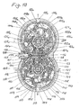
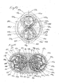
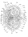
- An advantageous embodiment is the arrangement of two or more Rotationsschwenkkolbenmotoren 50, 50a, the rotationally oscillating mounted power parts, the pivoting piston 104, 104a, 104c, are supported in a certain range of circumferential movement against each other and so one or more Vortikarbeitsschreib 160, 160a, 161 or more expansion spaces 162, 163, 163a, 164, 164a, 164c and are driven by a cycle process according to the features of the method 2 according to claims 6 to 10.
- the volume flow of the working fluid is generated in the work area on the expansion side 162, 163, 163a, 164, 164a in the upper working chambers into mechanical energy via the pivot piston surfaces 115, 115a and the rotor radius a common adul Schlierendes torque.
- the torque in two rotors 102, 102a is twice as large, in three rotors 4 times as large as in a rotary pivot piston engine.
- the operation of the lower piston working chambers 108, 108a, 108b is particularly advantageous.
- the rotational energy is generated from the sum of the centrifugal forces, the rotating inertial forces and the expansion force of the prestressed working fluid and its effects via the pivoting pistons 104, 104a, 104b mounted with a rotation axis 132, 133, 134.
- the drive torque generated in this way works via the eccentricity 165 of the rotor axis 103 and housing guide ring 113 in the working direction of rotation with the lever arm of the rotor radius 102, 102a, 102b.
- the individual torques add up to a large drive torque to the motor shafts 103, 103a.
- the starting torque in all rotary swivel piston engines is very high in any position of the rotor 102, 102a, 102b, thus the rotary swivel piston engine also starts from a standstill under load and accelerates e.g. even a moving car and its masses immediately, since the motor drive has a low rotational mass inertia, which is 40% less than that of an electric drive. Further advantages are the stalling torque that is up to 30% above the starting torque, which protects the engine and its components from destruction.
- the rated torque is 65% of the starting torque and is constant over a wide range of speeds due to the double-acting operating swivel pistons 104.
- the Rotationsschwenkkotbenmotor 50, 50a can move a vehicle without a gearbox only on the pressure or throttle control 92, optimally and energy efficient on its drive shaft 53, this also applies to the power generation with a generator 90th
- the upper pre-pressure working chamber 160, 160a is centered radially in the direction of rotation via an optimal fluidically designed flow compressor 167 with the prestressed working fluid, the lower working chambers 108, 108a through the cylinder ceiling 142, 142a and cylindrical discs 141, 141a, leading bores 121, 122, 121a, 122a and channels 146, 147, 146a, 147a, axial depot chambers 117, 117a in the rotor bodies 102, 102a.
- the biased working fluid moves as described above with its volume flow through a flow compressor 167 via a pressure manifold 168 in the pre-pressure working chamber 160, 160a, 161.
- a pre-pressure chamber 160, 160a, 161 act two pivot pistons 104, 104a with their front pivot piston surfaces 115, 115a in the direction of rotation the rotors 102, 102a and two arcuate piston surfaces 109, 109a which act tangentially with the rotors 102, 102a and build up working fluid pressure.
- the mutually supporting pistons 104, 104a generate by the parallel operation no friction work and form at the apex of the circumferential movement with the Housing walls 101, 101a, 114, 114a, 113, 113a and rotating in front of them running rotary piston 104, 104a to a pressure chamber 162 with high potential pressure energy.
- This pressure energy is converted in the direction of rotation of the rotors 102, 102a into at least 4 to 6 expansion chambers 163, 164, 164a mechanical kinetic energy.
- the oscillating pistons 104, 104a roll off gas-tightly via a slightly toothed piston arc surface 179, 179a.
- the magnetic field acts repelling on the expansion side 162, 163, 163a, attracting on the upstream side 161 160, 160a and neutralizing the acting forces in the working region 161 to 162 in the direction of rotation by the magnetic attraction force on the parallel running pivot pistons.
- the magnetic field lines have the same polarity and repel each other, thereby producing a torque on the rotor axes 103, 103a.
- the motor housing 101, 101a is made of non-magnetic materials, ceramics, hard, carbon fiber and glass fiber plastics, as well as the rotor 102, 102a and the rotary pistons 104, 104a, in addition, the magnetic field on the material plate 200, 200a to the motor housing 101, 101a shielded.
- a sliding and friction body 199, 199a of a thermally conductive self-lubricating material combination is arranged in the working area 162, 162a, which does not allow the magnetic field lines of the magnetic field to pass even in the front third of the working area 162, 162a.
- Fig. 17 the arrangement is drawn schematically.
- the expansion pressure of the working fluid in the lower swing piston chamber 108 acts over the swing piston surfaces 110, 110a, the swing piston radius 118 and generates a torque in the expansion region 162, 163, 163a.
- the expansion pressure is regulated via the inlet 123 and the storage chamber 117 and the outlet 125.
- the rotational energy generates a high pressure pulse in the swivel piston chamber 108, which generates in the expansion region 163, 163a via the tangent of the parabolic track of the swivel pistons 104, 104a the rotor axes 103, 103 a very high torque, which is now still supported and added, to the generated torque of the upper pivot piston chamber 162 via the pivot piston surfaces 115 and the depot chamber 128 and the magnetic moment of the rotor plates 183, 183 a in the working area 162.
- Another advantageous embodiment is the arrangement of two Rotationsschwenkkolbenmotoren 50, 50a, the working direction of rotation is in opposite directions.
- the working fluid is retracted on both sides via a respective flow compressor 170, 171.
- the prestressed working fluid which is guided on both sides via a respective pressure distributor 172, meet in the cylindrical dossier chamber 174.
- pressure and temperature of the working fluid increases, the flow comes to a halt because the pivoting pistons 104, 104a, 104b with their Bogenradius vom 109, 109a and the Rotorenradiusbögen 173, 173a, the inlet openings 175, 176 to the two overhead working chambers 163, 163a close.
- the two pivot pistons 104, 104a release the inlet openings 175, 176.
- the working fluid is flowing now Housing walls 101, 101a, 114, 114a, 113, 113a and rotating in front of them running rotary piston 104, 104a to a pressure chamber 162 with high potential pressure energy.
- This pressure energy is converted in the direction of rotation of the rotors 102, 102a into at least 4 to 6 expansion chambers 163, 164, 164a mechanical kinetic energy.
- the oscillating pistons 104, 104a roll off gas-tightly via a slightly toothed piston arc surface 179, 179a.
- the magnetic field acts repelling on the expansion side 162, 163, 163a, attracting on the upstream side 161 160, 160a and neutralizing the acting forces in the working region 161 to 162 in the direction of rotation by the magnetic attraction force on the parallel running pivot pistons.
- the magnetic field lines have the same polarity and repel each other, thereby producing a torque on the rotor axes 103, 103a.
- the motor housing 101, 101a is made of non-magnetic materials, ceramics, hard, carbon fiber and glass fiber plastics, as well as the rotor 102, 102a and the rotary pistons 104, 104a, in addition, the magnetic field on the material plate 200, 200a to the motor housing 101, 101 a shielded.
- a sliding and friction body 199, 199a of a thermally conductive self-lubricating material combination is arranged in the working area 162, 162a, which does not allow the magnetic field lines of the magnetic field to pass even in the front third of the working area 162, 162a.
- Fig. 17 the arrangement is drawn schematically.
- the expansion pressure of the working fluid in the lower swing piston chamber 108 acts over the swing piston surfaces 110, 110a, the swing piston radius 118 and generates a torque in the expansion region 162, 163, 163a.
- the expansion pressure is regulated via the inlet 123 and the storage chamber 117 and the outlet 125.
- the rotational energy generates a high pressure pulse in the swivel piston chamber 108, which generates in the expansion region 163, 163a via the tangent of the parabolic track of the swivel pistons 104, 104a the rotor axes 103, 103 a very high torque, which is now still supported and added, to the generated torque of the upper pivot piston chamber 162 via the pivot piston surfaces 115 and the depot chamber 128 and the magnetic moment of the rotor plates 183, 183 a in the working area 162.
- Another advantageous embodiment is the arrangement of two Rotationsschwenkkolbenmotoren 50, 50a, the working direction of rotation is in opposite directions.
- the working fluid is retracted on both sides via a respective flow compressor 170, 171.
- the prestressed working fluid which is guided on both sides via a respective pressure distributor 172, meet in the cylindrical dossier chamber 174.
- pressure and temperature of the working fluid increases, the flow comes to a halt because the pivoting pistons 104, 104a, 104b with their Bogenradius vom 109, 109a and the Rotorenradiusbögen 173, 173a, the inlet openings 175, 176 to the two overhead working chambers 163, 163a close.
- the two pivot pistons 104, 104a release the inlet openings 175, 176.
- the working fluid is flowing now in the expansion chamber 163, 163 a and occupied at the same time two piston front surfaces 115, 115 a with the previously increased pressure of the working fluid.
- thermodynamic Polytrope operation is a pressure pulse work, comparable to a reciprocating engine, but without a 2 or 4-stroke system, without oscillating masses and vibrations, simply circular loaded with a large lever arm and with very low mass moments of inertia.
- An opposed swing piston engine unit 50, 50a with two rotary swivel engines has up to sixteen (sixteen) expansion chambers 163, 163a, 164, 164a, 108, 108a, 108b and generates twice the higher rotational speed and intake capacity of a comparable parallel working engine unit 50, 50a ,
- gears 166, 166a are mounted torque-proof, which engage in a planetary gear 177, which is torque-tight in the middle connected to the main drive shaft 178.
- a planetary gear 177 which is torque-tight in the middle connected to the main drive shaft 178.
- 103a can thus be tapped a left- and right-handed working direction of rotation without the rotors 102, 102a have to change their direction of rotation.
- Rotationsschwenkkolbenmotors 50 The design of the Rotationsschwenkkolbenmotors 50 is compact, the power to weight, the installation space required less, the starting torque higher and more robust and more flexible than an electric motor at overload in all speed ranges.
- the rotary swivel piston engine 50 is particularly versatile in its applications because it can be operated as a drive motor, as a pump and as a compressor. Via the lower pressure working chambers 108, 108a and the inlets 121, 122, 120, 119, 123, the output rotational direction can be changed, in left or right-hand rotor motor.
- the rotary swivel piston motor 50 is particularly suitable as a drive motor for all mobile vehicles, because the rotary swivel piston motor can be operated simultaneously or alternately as a motor or compressor.
- the rotary swivel piston motor can be operated simultaneously or alternately as a motor or compressor.
- the rotary swivel piston motor 50 can be assisted by the heating chamber 182 on the expansion side 112 via a water or oil circuit with thermal energy in its polytropic working process.
- the working process is cooled via the cooling chamber 181.
- the cylinder cover 142 are with Machine screws 191 screwed to the housing wall 101 firmly.
- An elastic, thermal resilient cylinder cover gasket 139 between the cylinder cover 142 and the side member 141 maintains a reliable working distance at a predetermined working temperature. Via the oil channels 192, the moving workpieces can be oiled.
- the aim of this invention is to provide a method for obtaining natural environmentally friendly work equipment, in addition to save the primary energy source electricity to improve the workload of the electric power plant and operate power plants independent of fuel environmentally friendly, ecological and economical.
- the effective efficiency of the conversion process is 81% for power to the working and storage means and is comparable to that of a water storage power plant.
- the production of work equipment should be cost-effective, technically feasible, decentralized, versatile, reliable, independent of raw materials, no hazardous substances, explosion-proof and free of additional environmental pollution.
- the renewable energy sources such as wind, water biomass, geothermal and photovoltaic are too precious to be burned and burned for mobile use only.
- the first method and claim 1 to 5 in which from the combustion exhaust gases of electric power plants, heating plants and industrial plants on the heat recovery, the cooling, filtering, molecular separation and gas liquefaction, the working fluid air, nitrogen, Oxygen and carbon dioxide is recovered.
- the working capacity (energy) of the above-mentioned equipment is between 615 to 636 kj / kg at an ambient temperature of 15 ° C.
- the amount of ice of 1 kg of dry ice CO 2 relative to 1 kg of water ice is 1.9 times higher.
- the extraction and storage of the working fluid can be carried out nationwide with effectively working multistage compressors or with gas liquefaction plants with electric drives via the primary energy source electricity.
- Electricity is the most qualitative and effective source of energy available in the world and can be obtained from many sources of energy. Humanity's quality of life and economic growth are inseparable from the energy source of electricity. Electricity is the energy source of the future. Using electricity and waste heat and gases from its generation via the energy storage technology makes ecological and economic sense and a positive challenge to the energy industry.
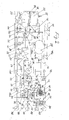
- the proposed solution in Fig. I drawn schematically and shows the first method according to claim 1 with an embodiment.
- the combustion gases are sent to the waste heat recovery 2, from there the exhaust gases are driven in the exhaust gas purification 3.
- the exhaust gases filtered in the exhaust gas purification are passed through the cooling tower 4 into the air and pollute, change the environment with the pollutants and especially the greenhouse gas carbon dioxide.
- the filtered and cooled combustion exhaust gas is moved from the cooling tower tip via a Abzugsersaugvorraum 5 through the intake manifold 6 by the negative pressure in the rotary swivel piston compressor 6.
- the compression system 6 pushes the exhaust gas through a highly effective working gas filter and gas separation plant 7. Pollutants and toxic gases such as carbon monoxide, benzenes, aerosols, nitrogen oxides, sulfur dioxide ust.
- Nitrogen and carbon dioxide are separated into one Gas liquefaction plant 8 driven.
- the liquefied gases are transported in cold-insulated tanks 9 and stored there. From the tanks 9, the liquid working fluid via pipes 10, tank container 11 and tanker 12 are distributed to the gas stations 13 and sold there via a secure tank technology to the consumer 14.
- the gas stations 13 are enriched the liquid working fluid nitrogen and carbon dioxide with liquid oxygen or compressed air from the compressor unit 15 and the gas pressure mixing station 16 and thus ent
- also controlled fuel media which promote a clean, economical and controlled oxidation of solid, liquid and gaseous biomass
- the working fluid is biased as compressed gas mixture with 200bar to 450bar and have a temperature of -60 ° C - 30 ° C.
- the working fluid carbon dioxide stands for this as an alternative, in liquid or solid matter, prepared as dry ice in pellet form in the dry ice plant 17 for use. All the above-mentioned tools can with the features of the 2nd method Fig.
- the working medium air and nitrogen can alternatively be stored in gaseous or liquid state, the working fluid carbon dioxide in liquid or solid state (dry ice) in tanks 20, 21.
- the storage pressure of the gaseous working medium air, nitrogen is up to 450bar the storage temperature to -60 ° C, in the saturated liquid state the storage temperature is up to minus 160 ° C.
- the storage pressure for the carbon dioxide is in the liquid state 20bar, the storage temperature -30 ° C , in the solid state in the form of dry ice, the storage pressure is a maximum of 15 bar, at a working temperature of minus 55 ° C.
- the average cooling capacity which is obtained in the system separate pore heat exchanger 24 via the volume flow and pressure control unit 22 and the expansion valve 23, is for the working fluid: gaseous air and nitrogen 11 KWh saturated liquid air and nitrogen 14KWh liquid carbon dioxide 19KWh solid (dry ice) 20KWh
- the carbon dioxide in pallet or granule form (eg 9mm ⁇ + 10-30mm long) is filled automatically via tank filler neck 95.
- tank filler neck 95 About the pressure control valve 97, the evaporator 98 and the three / two-way valve 99, the pressure in the storage tanks 20, 21 driven regulated.
- the energy for the evaporation pressure in the liquid working fluid and the sublimation pressure for the dry ice is free and environmentally friendly from the ambient air, which flows around the outside of the evaporator 98 forcibly.
- This ambient energy, from the ambient temperature, makes up to 12% of the mechanical kinetic energy, which is obtained at the end of the process according to the features of the second method according to claims 6 to 10.
- the heat recovery from the working fluid, which is in the cycle, at 3bär - 6bar and an operating temperature on average of 150 ° C, in a tube bundle countercurrent heat exchanger 28 is run in three separate systems.
- the working fluid from the circulation process isobar cooled to 15 to 40 ° C and heated from the storage tank 20, 21 working fluid heated to 100 ° C and thus increases the exergy and at the same time energy losses are avoided.
- the cooling process is supported by a heating water circuit 29 in counterflow.
- the working fluid in the circulation process reduces its volume flow by 30% with the same mass flow. This results in the compressor 31 30% less compression work.
- the advantages are an exergy increase for the working medium (proportional 5-20% of the circulatory mass flow) to be supplied and up to 30% less compaction work for the compressor 31.
- a car consumes 1500kg in city traffic for 100km ⁇ U> greenhouse ⁇ / u>
- 10 liters of gasoline 24kg CO 2
- 8 liters of diesel correspond 21 kg CO 2
- 10 liters of nitrogen correspond 0kg CO 2
- 10 liters of air 0kg CO 2
- the compressor 31 with its two-stage operation consists of three individual rotary swivel compressors 31, which are connected in series.
- the valve unit 35 switches the individual stages via three control valves and thus the compression acts like an elastically controlled delay.
- the working fluid he receives with a pre-pressure of 3 - 6bar from the countercurrent heat exchanger 28 via the third controlled system with the control valve 32 in the nominal load range.
- the working fluid he receives with a pre-pressure of 3 - 6bar from the countercurrent heat exchanger 28 via the third controlled system with the control valve 32 in the nominal load range.
- the compaction can take place via one stage, two stages or three stages.
- the compressor operates in single-load in the nominal load range, in two-stage in peak load and recuperation mode (braking energy) and in three stages in storage mode.
- the compressor 31 can store the working fluid air via the electric motor 36 and the energy medium current in the intermediate storage tank 37 via the thirteenth controlled system with the fourth pressure valve 38 at a storage pressure of up to 200bar.
- the tank 37 is insulated insulating and is additionally connected via the fourteenth controlled system with the first 3/2-way pressure valve 39 and the check valve 40 to the main storage tanks 20, 21, so that a cycle in the Häffugpli is possible.
- the power can be obtained via the existing power grid or generated via regenerative energy sources such as photovoltaic systems 41 or the fuel cell 42.
- regenerative energy sources such as photovoltaic systems 41 or the fuel cell 42.
- the waste heat of the oxidation is moved into the circulation process via the pipelines 34.
- Particularly consumer-friendly is when a small decentralized compressor system 44, the storage medium generates air and stored on the tanks 20, 21, 37, while the heat of compression can be used via a heating or hot water circuit 45.
- the compressor 44 If the compressor 44 generates compressed air of 300 liters, with 300 bar pressure, it pollutes 26KWh of work, stores 14KWh as exergy in the form of pressure energy and 8KWh in the form of thermal energy, the heating circuit 45 absorbs. Primary energy Energy + loss 26KWh 22 KWh + 4 KWh
- the compressor 31 is connected to the drive shaft 51 of the Rotationsschwenkkolbenmotors 50, with the drive gear 52, the drive axles 53 controlled by speed and torque via the control line 54.
- a high energy recovery rate is achieved, the braking energy via the torque circuit 55 effectively converted into pressure energy.
- the valve unit 35 of the compressor 31 is also controlled by the control power 54, that is, the operation of the compressor 31 in the step pressure ratio of single-stage, two-stage and three-stage operation.
- the compressor 31 operates polytropically and is cooled by the cooling circuit 26 of the consumer 45 and the countercurrent heat exchanger 56 of the preheating circuit 57 of the working fluid water.
- the compressor 31 From the compressor 31 is the biased working fluid of up to 150 ° C and a pressure of up to 14.5 bar through the three / two-way valve 58 in the flow compressor 48 via the pressure manifold 59 through the ring duffor 60 (flow delay) and the check flap 61st moved into the outer combustion chamber 62 of the expander unit 47.
- the function is that of a secondary current that protects the outer walls of the expander 47 from overheating. If the inert working medium nitrogen, carbon dioxide are stored in the tanks 20, 21, the second controlled system also drives the prestressed working medium into the secondary air flow.
- the second control path via the three / two-way valve 58 alternatively travels through the three / two-way valve 58 into the primary circuit into the internal heating combustion chamber 63 directly into the oxidation zones via a flow and pressure distributor 64.
- the expander unit 47 is a multi-fuel burner that can operate by hybrid operation with two different fuels.
- the internal heating combustion chamber 63 consists of a porous body 65 with effective heat transfer properties and the fuel distributor ring 66.
- the combustion system 65, 66 operates flameless with an oxidation temperature up to 1200 ° C.
- the oxidation time is up to 200 times greater than in the case of explosion combustion in a reciprocating engine.
- the continuous modulatable long-term combustion of the fuel in the combustion chambers 63, 62 is a thermodynamically favorable "contra-combustion" with a pulsed mode of operation that is electronically controlled.
- the flutter valve is designed according to fluid mechanical optimal requirements.
- the entire units are thermally insulated isolated.
- the fuel diversity is complemented by the solid alternative fuels such as wood, straw and waste in stationary operation.
- the expander unit 47 has two pore firing systems, a system separated atmosphere pore burner 69 up to 1 bar and a pulsed spore burner 62, 63 operating in the system under pressure up to 15 bar.
- Each burner system 62, 63 and 69 can operate individually or in parallel, as well different fuels of different consistency, in liquid form, solid or gaseous states are used.
- the pore burner systems proposed here can convert high-quality thermal energies over a wide power range with very low emissions into mechanical energy.
- the pulse sporeburn burner 62, 63 works with the biomass ethanol, methanol, biogas and biodiesel, the atmosphere pore burner 69 with the biomass wood straw and grass pellets also with biogas, hydrogen, natural gas, natural gases, biodiesel and all types of vegetable oil.
- the fuel is stored in tanks 70 and driven via a pressure pump with dosing unit 71 via the twelfth control path with the control valve 72 or optionally with the control valve 73 in the fuel distributor rings 66. The operation is controlled electronically.
- the atmosphere burner 69 from the fourth control line via the pressure control valve 43 from the primary circuit combustion air is controlled closed with overpressure.
- the waste heat of the expander unit 47 is recovered via the tube bundle exchanger 74 and the exhaust heat through the tube sheet heat exchanger 75 into useful thermal energy.
- the tenth controlled system runs the feed water from the tank 78 with the electronically controlled pump 79 through the Abgasrohrbündelpianoneter 75 via the volume control flow control valve 81 in the expansion valve 82 in the smallest cross section of the flow compressor 48.
- the gas pipe of the second controlled system which carries the primary gas stream, acts as an evaporation surface
- the waste heat of the expander unit 47 is systematically controlled by the feedwater circuit 76 through the tube bundle heat exchanger 74 via the eleventh controlled system and the volume flow valve 83 and the expansion valve 84 in the pore evaporator 85.
- a tube bundle heat exchanger 75 is integrated, it is connected to the heating water circuit 76 regulated by the consumer 77 via the circulation pump 80.
- the working fluid from the primary and secondary flow are mixed in the combustion chambers 63, 62 of the expander unit 47.
- the dosed injected water from the tenth controlled system is evaporated.
- the steam is superheated, then mixed with the combustion gases and the gaseous working fluid to a pulse-compressed gas mixture, driven at a working temperature of 750 ° C and a pulse-pressure operation of 6bar to 15bar via the flow compressor 67 in the pore evaporator 85.
- the mass fraction of the injected water over the tenth controlled system in expander unit 47 has the task and function of reducing and minimizing the material loading of the expander unit 47, achieving a high and rapid heat transfer between the working equipment and the oxidizing gases, having a higher energy density of the working equipment and to minimize the pollutants from the oxidation of oily and solid biomass.
- the void evaporator 85 is made of a foamed ceramic of silicon carbide or alternatively of foamed metal alloys of copper, iron, aluminum.
- the foam body 86 has open small pores through which flow the working fluid, there are and arise residence times for chemical physical and thermal reactions of the working materials with each other.
- the void evaporator 85 is also a mass converter, an oxidation catalyst, a denitrification catalyst, an exhaust gas cleaner and also a soot particle filter.
- a 1cm 3 foam body corresponds to up to 12cm 2 exchange surface for thermal and chemical reactions.
- the working medium gas mixture of air, nitrogen, carbon dioxide and water vapor leaves the pore evaporator 85 with a controlled temperature range of 350 ° C - 500 ° C and a mixed steam gas pressure of up to 15bar.
- the mass fraction of water is determined by the working flow process and the composition of the fuel gases.
- the pressure volume flow valve 87 the working fluid mixture is moved into the upper working chamber of the Rotationsschwenkkolbenmotors 50 and driven via the pressure control unit 88 in the lower working chamber of the Rotationsschwenkkolbenmotors.
- the inlet pressures are regulated differently, so the upper working chamber is operated from 4 to 8 bar, the lower working chamber with 8 to 15 bar inlet pressure.
- the rotary swivel piston engine 50 converts the thermal, rotational, kinetic and potential pressure energy of the working medium gas mixture into mechanical energy via motor shafts 53.
- the rotary swivel piston engine 50 converts the thermal, rotational, kinetic and potential pressure energy of the working medium gas mixture into mechanical energy via motor shafts 53.
- the rotary swivel piston motor 50 operates as an expansion motor simultaneously, controlled by the exhaust ports, exhaust ports, the pressure expansion valve 91, and the throttle, condenser and muffler exhaust units 92.
- the exhaust gas volumetric flow rate is electronically controlled via the parameters from the required performance data via the throttle unit 92.
- the versatile function of the unit 92 is made possible by a foam metal pore body 93.
- the compressed in Rotationsschwenkkolbenmotor work equipment is moved through the pipe 100 into the tube bundle heat exchanger 28 and with this step, the circulation process is closed. About the water cycle with the pump 95, the compressor zone is cooled and heated the expansion zone.
- the Rotationsschwenkkolbenmotor 50, the throttle unit 92 are thermally insulating and sound-insulating isolated.
- the controlled system sixteen with the control valve 94 carries ambient air into the rotary swivel piston engine 50. With the valve 94 open, the rotary swivel piston motor 50 operates as a first compression stage, for example in the recuperation of inertia forces and presses the prestressed air through the pipe 100 in the cycle process.
Landscapes
- Engineering & Computer Science (AREA)
- Mechanical Engineering (AREA)
- General Engineering & Computer Science (AREA)
- Chemical & Material Sciences (AREA)
- Combustion & Propulsion (AREA)
- Chemical Kinetics & Catalysis (AREA)
- Engine Equipment That Uses Special Cycles (AREA)
- Compressors, Vaccum Pumps And Other Relevant Systems (AREA)
Applications Claiming Priority (1)
| Application Number | Priority Date | Filing Date | Title |
|---|---|---|---|
| DE200610020875 DE102006020875A1 (de) | 2005-08-24 | 2006-05-05 | Verfahren zur Gewinnung, Speicherung und Nutzung von Arbeitsmitteln durch einen Rotationsschwenkkolbenmotor |
Publications (1)
| Publication Number | Publication Date |
|---|---|
| EP1852576A2 true EP1852576A2 (fr) | 2007-11-07 |
Family
ID=38331684
Family Applications (1)
| Application Number | Title | Priority Date | Filing Date |
|---|---|---|---|
| EP07009041A Withdrawn EP1852576A2 (fr) | 2006-05-05 | 2007-05-04 | Procédé de récupération, d' emmagasinage et de préparation d' agents de travail, procédé d' utilisation d' agents de travail avec un moteur à piston oscillant |
Country Status (2)
| Country | Link |
|---|---|
| EP (1) | EP1852576A2 (fr) |
| DE (1) | DE102006062741B4 (fr) |
Cited By (4)
| Publication number | Priority date | Publication date | Assignee | Title |
|---|---|---|---|---|
| WO2015169861A1 (fr) * | 2014-05-06 | 2015-11-12 | VBE Berlin-Mechanik GmbH | Moteur à pistons rotatifs, procédé pour faire fonctionner un moteur à pistons rotatifs, système de moteurs et véhicule à moteur |
| CN108170190A (zh) * | 2018-01-18 | 2018-06-15 | 南京航空航天大学 | 一种利用飞行器燃油箱惰化系统中废热发电的装置 |
| US11306591B2 (en) * | 2018-09-10 | 2022-04-19 | Vengeance Power Inc. | Rotary device |
| US12036507B2 (en) | 2022-02-15 | 2024-07-16 | International Business Machines Corporation | Compressible fluid separator pump |
Family Cites Families (6)
| Publication number | Priority date | Publication date | Assignee | Title |
|---|---|---|---|---|
| US3786631A (en) * | 1971-09-23 | 1974-01-22 | L Manning | Nitrogen vapor engine |
| US4990168A (en) * | 1989-07-17 | 1991-02-05 | Sauer Richard A | Recovery of carbon dioxide from a carbon dioxide plant vent gas using membranes |
| DE4422595C1 (de) * | 1994-06-28 | 1995-09-21 | Saarbergwerke Ag | Verfahren zur Verbesserung der Ausbreitung der in der Anfahrphase eines Kraftwerkes anfallenden und über den Kühlturm in die Atmosphäre abzuleitenden Rauchgase |
| EP0831205B1 (fr) * | 1996-09-20 | 2004-05-12 | Kabushiki Kaisha Toshiba | Système de production d'énergie capable de la séparation et de la récupération du dioxyde de carbone |
| DE10319895B4 (de) * | 2003-04-28 | 2009-05-07 | Bernau, Klaus-Jürgen | Rotationsschwenkkolbenmotor |
| DE10352520B4 (de) * | 2003-11-04 | 2006-11-02 | Klaus Herrmann | Verfahren zum Betreiben einer stationären oder mobilen Kraftmaschine mittels Druckgas und Einrichtung zur Durchführung des Verfahrens |
-
2006
- 2006-05-05 DE DE102006062741A patent/DE102006062741B4/de not_active Expired - Fee Related
-
2007
- 2007-05-04 EP EP07009041A patent/EP1852576A2/fr not_active Withdrawn
Cited By (4)
| Publication number | Priority date | Publication date | Assignee | Title |
|---|---|---|---|---|
| WO2015169861A1 (fr) * | 2014-05-06 | 2015-11-12 | VBE Berlin-Mechanik GmbH | Moteur à pistons rotatifs, procédé pour faire fonctionner un moteur à pistons rotatifs, système de moteurs et véhicule à moteur |
| CN108170190A (zh) * | 2018-01-18 | 2018-06-15 | 南京航空航天大学 | 一种利用飞行器燃油箱惰化系统中废热发电的装置 |
| US11306591B2 (en) * | 2018-09-10 | 2022-04-19 | Vengeance Power Inc. | Rotary device |
| US12036507B2 (en) | 2022-02-15 | 2024-07-16 | International Business Machines Corporation | Compressible fluid separator pump |
Also Published As
| Publication number | Publication date |
|---|---|
| DE102006062741A1 (de) | 2007-12-27 |
| DE102006062741B4 (de) | 2011-06-16 |
Similar Documents
| Publication | Publication Date | Title |
|---|---|---|
| DE69329459T2 (de) | Gaskompressor | |
| US6955052B2 (en) | Thermal gas compression engine | |
| EP0749521B1 (fr) | Procede pour une transformation faiblement polluante de combustibles fossiles en energie motrice | |
| CN204877548U (zh) | 经济利用压缩空气为汽车动力源的系统 | |
| DE69930423T2 (de) | Motor | |
| CN107407228B (zh) | 传递-膨胀和再生型热力发动机 | |
| DE10392525T5 (de) | Verfahren, Prozesse, Systeme und Vorrichtung mit Wasserverbrennungstechnologie zur Verbrennung von Wasserstoff und Sauerstoff | |
| WO2011066964A2 (fr) | Dispositif d'exploitation de la chaleur, alimenté par la chaleur dissipée | |
| EP4028489B1 (fr) | Dispositif et procédé comprenant deux sous-systèmes destinés à utiliser des combustibles à base de carbone dans des moteurs à combustion interne dans un fonctionnement en circuit, permettant de réutiliser le produit d'oxydation accumulé et d'entraîner un agent oxydant sur le moyen de transport | |
| DE102008050014A1 (de) | Zink'sche Tangential-Verbrennung Turbine | |
| EP4237668A1 (fr) | Ensemble turbine | |
| US8978619B1 (en) | Pistonless rotary engine with multi-vane compressor and combustion disk | |
| DE102006062741B4 (de) | Verfahren zur Gewinnung, Speicherung und Aufbereitung von flüssigen Arbeitsmitteln und ein Verfahren zur Nutzung der Arbeitsmittel über einem Rotationsschwenkkolbenmotor | |
| DE102006020875A1 (de) | Verfahren zur Gewinnung, Speicherung und Nutzung von Arbeitsmitteln durch einen Rotationsschwenkkolbenmotor | |
| RU193641U1 (ru) | Роторный пневматический двигатель-компрессор с функцией двигателя внутреннего сгорания | |
| EP2526177B1 (fr) | Dispositifs sans émission pour effectuer des travaux mécaniques | |
| EP1529928B1 (fr) | Moteur écocompatible à piston rotatif actionné par un gas sous pression et son procédé à cycle thermodynamique | |
| DE102017002286A1 (de) | Hydridwärmekraftanlage mit zwei Vorrichtungen zur Umwandlung von Wärme in mechanische Energie Ermöglicht mit einer isochor arbeitenden Arbeitsmaschine, einem Hybridwärmekreislaufprozess und einer isotherm arbeitenden Wärmekraftmaschine. | |
| EP2042688A2 (fr) | Appareil destiné à l'utilisation de la différence de pression de milieux gazeux ou liquides par leur conversion en rotation | |
| WO2007120074A2 (fr) | Moteur à turbo-piston et compresseur à turbo-piston | |
| DE102016008835A1 (de) | Integrierte Abgasverwertungs - und Kraftstoffvergasungsanlage für Verbrennungsmotoren aller Art | |
| DE102021001224A1 (de) | Drehkolben-Expander mit Kryo-Kraftstoffen, geeignet sowohl für die Mobilitätsindustrie als auch für andere Anwendungen, besonders als Kraftmaschine für Kern-Dampferzeuger | |
| DE4240871A1 (de) | Flüssiger Kolben in Arbeitsmaschinen, z. B. in Verdichtern und Antriebsmaschinen | |
| DE102005039993A1 (de) | Alternatives, umweltfreundliches Energiewandelsystem mit einem Rotationskreiskolbenmotor | |
| DE19954480A1 (de) | Rotationskolben-Verbrennungsmaschine |
Legal Events
| Date | Code | Title | Description |
|---|---|---|---|
| PUAI | Public reference made under article 153(3) epc to a published international application that has entered the european phase |
Free format text: ORIGINAL CODE: 0009012 |
|
| AK | Designated contracting states |
Kind code of ref document: A2 Designated state(s): AT BE BG CH CY CZ DE DK EE ES FI FR GB GR HU IE IS IT LI LT LU LV MC MT NL PL PT RO SE SI SK TR |
|
| AX | Request for extension of the european patent |
Extension state: AL BA HR MK YU |
|
| STAA | Information on the status of an ep patent application or granted ep patent |
Free format text: STATUS: THE APPLICATION IS DEEMED TO BE WITHDRAWN |
|
| 18D | Application deemed to be withdrawn |
Effective date: 20121201 |