EP1852385A2 - Steps for escalator with high speed inclined section - Google Patents
Steps for escalator with high speed inclined section Download PDFInfo
- Publication number
- EP1852385A2 EP1852385A2 EP07015889A EP07015889A EP1852385A2 EP 1852385 A2 EP1852385 A2 EP 1852385A2 EP 07015889 A EP07015889 A EP 07015889A EP 07015889 A EP07015889 A EP 07015889A EP 1852385 A2 EP1852385 A2 EP 1852385A2
- Authority
- EP
- European Patent Office
- Prior art keywords
- link
- section
- roller shaft
- steps
- link roller
- Prior art date
- Legal status (The legal status is an assumption and is not a legal conclusion. Google has not performed a legal analysis and makes no representation as to the accuracy of the status listed.)
- Granted
Links
Images


Classifications
-
- B—PERFORMING OPERATIONS; TRANSPORTING
- B66—HOISTING; LIFTING; HAULING
- B66B—ELEVATORS; ESCALATORS OR MOVING WALKWAYS
- B66B21/00—Kinds or types of escalators or moving walkways
- B66B21/02—Escalators
- B66B21/025—Escalators of variable speed type
-
- B—PERFORMING OPERATIONS; TRANSPORTING
- B66—HOISTING; LIFTING; HAULING
- B66B—ELEVATORS; ESCALATORS OR MOVING WALKWAYS
- B66B21/00—Kinds or types of escalators or moving walkways
- B66B21/10—Moving walkways
- B66B21/12—Moving walkways of variable speed type
-
- B—PERFORMING OPERATIONS; TRANSPORTING
- B66—HOISTING; LIFTING; HAULING
- B66B—ELEVATORS; ESCALATORS OR MOVING WALKWAYS
- B66B23/00—Component parts of escalators or moving walkways
- B66B23/08—Carrying surfaces
- B66B23/12—Steps
Definitions
- This invention relates to an escalator with a high speed inclined section in which the steps move faster in the intermediate inclined section than in the upper and lower landing sections.
- an escalator with a high speed inclined section which is driven at low speed in the upper and lower landing sections where the passenger gets on or off, accelerated or decelerated in the upper and lower curved sections, and driven at high speed in the intermediate inclined section, whereby the requisite time for the passenger to ride on the escalator is shortened.
- An example of such an escalator with a high speed inclined section is disclosed in Japanese Patent Application Laid-open No. Sho 51-116586 .
- the present invention has been made in view of the above-mentioned problems, and an object of the present invention is to obtain an escalator with a high speed inclined section which is capable of preventing interference of a tread with a riser of an adjacent step or generation of a gap between the riser and the tread in upper and lower landing sections and intermediate inclined sections.
- an escalator with a high speed inclined section wherein assuming that an upper-step-side end of a tread is the origin of a coordinate system when a step is seen from a side with the tread being horizontal and on the upper side, a riser passes a point whose horizontal and vertical coordinates can be expressed as follows: (where k is a speed change ratio; r is a distance between the step link roller shafts of the steps adjacent to each other in upper and lower landing sections; and ⁇ m is an inclination angle of a intermediate inclined section).
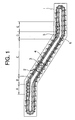
- Fig. 1 is a schematic side view of an escalator with a high speed inclined section according to an embodiment of this invention.
- a main frame 1 is provided with a plurality of steps 2 connected together in an endless fashion.
- the steps 2 are driven by a drive unit (step driving means) 3 and circulated.
- the main frame 1 is provided with a pair of main tracks 4 forming a loop track for the steps 2, a pair of trailing tracks 5 for controlling the attitude of the steps 2, and a pair of auxiliary tracks 6 for varying the distance between adjacent steps 2.
- the loop track for the steps 2 has a forward path section, a return track section, an upper reversing section, and a lower reversing section.
- the forward path section of the loop track has an upper landing section (upper horizontal section) A , an upper curved section B , an intermediate inclined section (fixed inclination section) C , a lower curved section D , and a lower landing section (lower horizontal section) E .
- the intermediate inclined section C is situated between the upper landing section A and the lower landing section E .
- the upper curved section B is situated between the upper landing section A and the intermediate inclined section C .
- the lower curved section D is situated between the lower landing section E and the intermediate inclined section C .
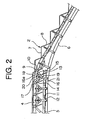
- Fig. 2 is an enlarged side view of the portion around the upper curved section B of Fig. 1.
- Each step 2 has a tread 7 for carrying the passenger, a riser 8 formed by bending the lower step side portion of the tread 7, a step link roller shaft 9 extending in the width direction of the tread 7, a pair of step link rollers 10 rotatable around the step link roller shaft 9, a trailing roller shaft 11 parallel to the step link roller shaft 9, and a pair of trailing rollers 12 rotatable around the trailing rollers 11.
- the step link rollers 10 roll on the main tracks 4.
- the trailing rollers 12 roll on the trailing tracks 5.
- step link roller shafts 9 of adjacent steps 2 are connected to each other by a pair of link mechanisms (folding links) 13.
- Each link mechanism 13 has first through fifth links 14 through 18.
- One end portion of the first link 14 is rotatably connected to the step link roller shaft 9.
- the other end portion of the first link 14 is rotatably connected to the middle portion of the third link 16 through a shaft 19.
- One end portion of the second link 15 is rotatably connected to the step link roller shaft 9 of the adjacent step 2.
- the other end portion of the second link 15 is rotatably connected to the middle portion of the third link 16 through the shaft 19.
- One end portion of the fourth link 17 is rotatably connected to the middle portion of the first link 14.
- One end portion of the fifth link 18 is rotatably connected to the middle portion of the second link 15.
- the other end portions of the fourth and fifth links 17 and 18 are connected to one end portion of the third link 16 through a slide shaft 20.
- a guide groove 16a for guiding the sliding of the slide shaft 20 in the longitudinal direction of the third link 16.
- a rotatable auxiliary roller 21 At the other end of the third link 16, there is provided a rotatable auxiliary roller 21. The auxiliary roller 21 is guided by the auxiliary track 6.
- the step speed changing means in Embodiment 1 has the auxiliary track 6, the link mechanism 13, and the auxiliary roller 21.
- the speed of the steps 2 is varied by varying the distance between the step link roller shafts 9 of the adjacent steps 2. That is, in the upper landing section A and the lower landing section E where the passenger gets on or off, the distance between the step link roller shafts 9 is minimum, and the steps 2 move at low speed. In the intermediate inclined section C , the distance between the step link roller shafts 9 is maximum, and the steps 2 move at high speed. In the upper curved section B and the lower curved section D constituting the speed changing portions, the distance between the step link roller shafts 9 is varied, and the steps 2 are accelerated or decelerated.
- the first, second, fourth, and fifth links 14, 15, 17, and 18 form a so-called pantograph type quadruple link mechanism, making it possible to increase or decrease the angle made by the first and second links 14 and 15, with the third link 16 serving as the axis of symmetry, whereby it is possible to vary the distance between the step link roller shafts 9 connected to the first and second links 14 and 15.
- the distance between the step link roller shafts 9 of the adjacent steps 2 is minimum.
- the link mechanism 13 operates like the framework of an umbrella when it is opened, and the distance between the step link roller shafts 9 of the adjacent steps 2 increases.
- the distance between the main track 4 and the auxiliary track 6 is minimum, and the distance between the step link roller shafts 9 of the adjacent steps 2 is maximum.
- the speed of the steps 2 is maximum.
- the first and second links 14 and 15 are substantially arranged in a straight line.
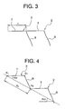
- Fig. 3 is an explanatory diagram showing the positional relationship between the adjacent steps 2 in the upper and lower landing sections A and E of Fig. 1
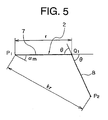
- Fig. 4 is an explanatory diagram showing the positional relationship between the adjacent steps 2 in the intermediate inclined section C of Fig. 1.
- the steps 2 are arranged horizontally with no gaps therebetween, and the distance between the step link roller shafts 9 of the adjacent steps 2 (or the distance between identical corresponding points) is r.
- the speed changing ratio (the ratio of the moving speed of the steps 2 in the intermediate inclined section C to the moving speed of the steps 2 in the upper and lower landing sections A and E) is k .
- the inclination angle of the intermediate inclined section is ⁇ m .
- the distance between the adjacent steps 2 in the intermediate inclined section C is kr.
- the coordinates of the upper-step-side end P 2 of the tread 7 of the step 2 situated on the lower step side can be expressed as follows: krcos ⁇ m , - krsin ⁇ m
- the configuration of the riser 8 is determined so as to be a straight line or a curved line passing the lower-step-side end Q 1 of the tread 7 and the upper-step-side end P 2 of the tread 7 of the step 2 adjacent on the lower step side, whereby it is possible to prevent the tread 7 from interfering with the riser 8 of the adjacent step 2 and to prevent generation of a gap between the riser 8 and the tread 7 in the upper and lower landing sections A and E and the intermediate inclined section C .
- Fig. 5 is an explanatory diagram showing the riser configuration in the escalator with a high speed inclined section of Embodiment 2 of this invention.
- the general construction of the escalator is the same as that of Embodiment 1.
- the riser 8 has a flat configuration. That is, when the step 2 is seen from the side, the riser 8 exhibits a straight line passing the lower-step-side end Q 1 of the tread 7 and the upper-step-side end P 2 of the tread 7 of the step 2 adjacent on the lower step side.
- ⁇ krsin ⁇ m / krcos ⁇ m - 1
- the angle ⁇ of the riser 8 with respect to the tread 7 is restricted by the speed changing ratio k and the inclination angle ⁇ m of the intermediate inclined section C , whereby it is possible to prevent the tread 7 from interfering with the riser 8 of the adjacent step 2 and to prevent generation of a gap between the riser 8 and the tread 7 in the upper and lower landing sections A and E and the intermediate inclined section C.
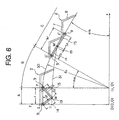
- Fig. 6 is an explanatory diagram showing the movement locus of the link connection point around the upper curved section of an escalator with a high speed inclined section according to Embodiment 3 of this invention.
- the general construction of the escalator is the same as that of Embodiment 1.
- the axis of the step link roller shaft 9 moves along the movement locus 30.
- the adjacent steps 2 are arranged horizontally without any gap therebetween, and the distance between the axes of the step link roller shafts 9 (which is substantially equal to the length of the tread 7) is r.
- the speed changing ratio (the ratio of the moving speed of the steps 2 in the intermediate inclined section C to the moving speed of the steps 2 in the upper and lower landing sections A and E ) is k .
- the inclination angle of the intermediate inclined section C is ⁇ m .
- the radius of curvature of the movement locus 30 in the upper curved section B is R 1 .
- the distance between the step link roller shafts 9 in the intermediate inclined section C is kr.
- the length of the portion of the first link 14 from the step link roller shaft 9 to the link connection point (which is substantially equal to the length of the first link 14) is L 1
- the length of the portion of the second link 15 from the step link roller shaft 9 to the link connection point (which is substantially equal to the length of the second link 15) is L 2 .
- the step link roller shaft 9 and the link connection point in the first link 14 and the step link roller shaft 9 in the second link 15 are defined to be in a straight line.
- the coordinates of one end M and the other end M' of the movement locus 31 of the link connection point in the speed changing region are obtained. It is to be assumed that the speed change in the upper portion of the escalator (the folding and stretching of the first link 14 and the second link 15) is completed exclusively in the upper curved section B . Further, the origin of the coordinate system is the point spaced apart horizontally (in the x-direction) by -r and vertically (in the y-direction) by -R 1 from the border point F which is in the movement locus 30 of the axis of the step link roller shaft 9 and which is between the upper landing section A and the upper curved section B.
- the step link roller shaft 9 and the link connection point in the first link 14 and the step link roller shaft 9 in the second link 15 are in a straight line, so that M' is a point which is in the movement locus 30 of the axis of the step link roller shaft 9 and in the intermediate inclined section C.
- the movement locus 31 of the link connection point in the speed change region of the upper portion of the escalator is a straight line or a curved line connecting the end points M and M'. That is, the positions of the end points of the link connection point are determined such that the speed change of the steps 2 in the upper portion of the escalator is effected exclusively in the upper curved section B (the region where the steps 2 undergo a change in difference in level).
- the upper and lower landing sections A and E and the intermediate inclined section C it is possible to prevent interference of the tread 7 with the riser 8 of the adjacent step 2 and generation of a gap between the riser 8 and the tread 7.
- Fig. 7 is an explanatory diagram showing the movement locus of the link connection point near the lower curved section of an escalator with a high speed inclined section according to Embodiment 4 of this invention.
- the general construction of the escalator is the same as that of Embodiment 1.
- the speed change in the lower portion of the escalator is completed exclusively in the lower curved section D .
- the radius of curvature of the movement locus 30 of the axis of the step link roller shaft 9 in the lower curved section D is R 2 .
- the origin of the coordinate system is the point spaced apart horizontally (in the x-direction) by r and vertically (in the y-direction) by R 2 from the border point I which is in the movement locus 30 and which is between the lower landing section E and the lower curved section D .
- the movement locus 31 of the link connection point in the speed changing region of the lower portion of the escalator is a straight line or a curved line having the points N and N' as its ends. That is, the positions of the end points of the link connection point are determined such that the speed change of the steps 2 in the lower portion of the escalator is effected exclusively in the lower curved section D (the region where the steps 2 undergo a change in difference in level).
- the upper and lower landing sections A and E and the intermediate inclined section C it is possible to prevent interference of the tread 7 with the riser 8 of the adjacent step 2 and generation of a gap between the riser 8 and the tread 7.
- Embodiments 3 and 4 While in Embodiments 3 and 4 the positions of the end points of the movement locus of the link connection point in the speed changing region (upper and lower curved sections) are obtained, it is also possible to geometrically obtain, from the positions of the points obtained, the positions of the end points of the movement locus of the axis of the auxiliary roller and the positions of the end points of the auxiliary track in the speed changing region.
- the link mechanism 41 has a first link 42 with a bent middle portion and a second link 43 of a linear configuration.
- One end portion of the first link 42 is connected to the step link roller shaft 9.
- An auxiliary roller 21 is mounted to the other end portion of the first link 42.
- One end portion of the second link 43 is connected to the step link roller shaft 9 of the adjacent step 2.
- the other end portion of the second link 43 is connected to the link connection point in the middle portion of the first link 42 through a shaft 44.
- the step speed changing means of Embodiment 5 has the auxiliary track 6, the link mechanism 41, and the auxiliary roller 21.
Landscapes
- Escalators And Moving Walkways (AREA)
Abstract
(krcosαm, -krsinαm) (where k is a speed change ratio; r is a distance between the step link roller shafts (9) of the steps adjacent to each other in upper and lower landing sections (A,E); and α m is an inclination angle of an intermediate inclined section C).
Description
- This invention relates to an escalator with a high speed inclined section in which the steps move faster in the intermediate inclined section than in the upper and lower landing sections.
- Nowadays, a large number of escalators of great height are installed in subway stations or the like. In an escalator of this type, the passenger is obliged to stand on a step for a long period of time, which is often rather uncomfortable. In view of this, a high-speed escalator has been developed. However, in such a high-speed escalator, there is a limitation regarding the traveling speed from the viewpoint of allowing the passengers to get off and on safely.
- In view of this, there has been proposed an escalator with a high speed inclined section which is driven at low speed in the upper and lower landing sections where the passenger gets on or off, accelerated or decelerated in the upper and lower curved sections, and driven at high speed in the intermediate inclined section, whereby the requisite time for the passenger to ride on the escalator is shortened. An example of such an escalator with a high speed inclined section is disclosed in
Japanese Patent Application Laid-open No. Sho 51-116586 - However, conventional escalators with a high speed inclined section only exhibit a mechanism for realizing a change in the speed of the steps. Thus, if this speed changing mechanism is simply applied to an ordinary escalator, there is the danger, for example, of a gap being generated between a tread and a riser of an upper adjacent step or interference occurring between adjacent steps.
- The present invention has been made in view of the above-mentioned problems, and an object of the present invention is to obtain an escalator with a high speed inclined section which is capable of preventing interference of a tread with a riser of an adjacent step or generation of a gap between the riser and the tread in upper and lower landing sections and intermediate inclined sections.
- To this end, according to one aspect of the present invention, there is provided an escalator with a high speed inclined section, wherein assuming that an upper-step-side end of a tread is the origin of a coordinate system when a step is seen from a side with the tread being horizontal and on the upper side, a riser passes a point whose horizontal and vertical coordinates can be expressed as follows: (where k is a speed change ratio; r is a distance between the step link roller shafts of the steps adjacent to each other in upper and lower landing sections; and αm is an inclination angle of a intermediate inclined section).
- Accordingly, it is possible to prevent the tread from interfering with the riser of the adjacent step and to prevent generation of a gap between the riser and the tread in the upper and lower landing sections and the intermediate inclined section.
- According to another aspect of the present invention, there is provided an escalator with a high speed inclined section, wherein assuming that, when steps are seen from a side, a point spaced apart horizontally by -r and vertically by -R1 from a border point which is in movement locus of an axis of a step link roller shaft and which is between an upper landing section and an upper curved section is the origin of a coordinate system and that the horizontal and vertical coordinates of one end M and the other end M' of a movement locus of a link connection point in a speed changing region of an upper curved section are:

the following equations hold true:


(where r is the distance between the step link roller shafts in the upper and lower landing sections; L1 is the length between the step link roller shaft and the link connection point in a first link; k is a speed change ratio; and R1 is a radius of curvature of the upper curved section in the movement locus of the axis of the step link roller shaft). - Accordingly, in the upper and lower landing sections and an intermediate inclined section, it is possible to prevent interference of the tread with a riser of the adjacent step and generation of a gap between the riser and the tread.
- According to a still further aspect of the present invention, there is provided an escalator with a high speed inclined section, wherein assuming that, when steps are seen from a side, a point spaced apart horizontally by r and vertically by R2 from a border point which is in movement locus of an axis of a step link roller shaft and which is between a lower landing section and a lower curved section is the origin of a coordinate system and that horizontal and vertical coordinates of one end N and the other end N' of a line indicating a movement locus of a link connection point in a speed changing region of the lower curved section are:

the following equations hold true:


(where r is the distance between the step link roller shafts in the upper and lower landing sections; L1 is the length between the step link roller shaft and the link connection point in a first link; k is a speed change ratio; and R2 is a radius of curvature of the lower curved section in the movement locus of the axis of the step link roller shaft). - Accordingly, in the upper and lower landing sections and an intermediate inclined section, it is possible to prevent interference of the tread with a riser of the adjacent step and generation of a gap between the riser and the tread.
- In the accompanying drawings:
- Fig. 1 is a schematic side view of an escalator with a high speed inclined section according to an embodiment of this invention;
- Fig. 2 is an enlarged side view of the portion around an upper curved section of Fig. 1;
- Fig. 3 is an explanatory diagram illustrating the positional relationship between adjacent steps in upper and lower landing sections of Fig. 1;
- Fig. 4 is an explanatory diagram illustrating the positional relationship between adjacent steps in the intermediate inclined section of Fig. 1;
- Fig. 5 is an explanatory diagram illustrating the riser configuration of a step according to
Embodiment 2 of this invention; - Fig. 6 is an explanatory diagram illustrating the movement track of a link connecting point near an upper curved section of an escalator with a high speed inclined section according to
Embodiment 3 of this invention; - Fig. 7 is an explanatory diagram illustrating the movement track of a link connecting point near a lower curved section of an escalator with a high speed inclined section according to
Embodiment 4 of this invention; and - Fig. 8 is a side view of an upper reversing section of an escalator with a high speed inclined section according to
Embodiment 5 of this invention. - Embodiments of this invention will be described with reference to the drawings.
- Fig. 1 is a schematic side view of an escalator with a high speed inclined section according to an embodiment of this invention. In the drawing, a main frame 1 is provided with a plurality of
steps 2 connected together in an endless fashion. Thesteps 2 are driven by a drive unit (step driving means) 3 and circulated. - The main frame 1 is provided with a pair of
main tracks 4 forming a loop track for thesteps 2, a pair oftrailing tracks 5 for controlling the attitude of thesteps 2, and a pair ofauxiliary tracks 6 for varying the distance betweenadjacent steps 2. - The loop track for the
steps 2 has a forward path section, a return track section, an upper reversing section, and a lower reversing section. The forward path section of the loop track has an upper landing section (upper horizontal section) A, an upper curved section B, an intermediate inclined section (fixed inclination section) C, a lower curved section D, and a lower landing section (lower horizontal section) E. The intermediate inclined section C is situated between the upper landing section A and the lower landing section E. The upper curved section B is situated between the upper landing section A and the intermediate inclined section C. The lower curved section D is situated between the lower landing section E and the intermediate inclined section C. - Next, Fig. 2 is an enlarged side view of the portion around the upper curved section B of Fig. 1. Each
step 2 has atread 7 for carrying the passenger, ariser 8 formed by bending the lower step side portion of thetread 7, a steplink roller shaft 9 extending in the width direction of thetread 7, a pair ofstep link rollers 10 rotatable around the steplink roller shaft 9, atrailing roller shaft 11 parallel to the steplink roller shaft 9, and a pair oftrailing rollers 12 rotatable around thetrailing rollers 11. Thestep link rollers 10 roll on themain tracks 4. Thetrailing rollers 12 roll on thetrailing tracks 5. - The step
link roller shafts 9 ofadjacent steps 2 are connected to each other by a pair of link mechanisms (folding links) 13. Eachlink mechanism 13 has first throughfifth links 14 through 18. - One end portion of the
first link 14 is rotatably connected to the steplink roller shaft 9. The other end portion of thefirst link 14 is rotatably connected to the middle portion of thethird link 16 through ashaft 19. One end portion of thesecond link 15 is rotatably connected to the steplink roller shaft 9 of theadjacent step 2. The other end portion of thesecond link 15 is rotatably connected to the middle portion of thethird link 16 through theshaft 19. - One end portion of the
fourth link 17 is rotatably connected to the middle portion of thefirst link 14. One end portion of the fifth link 18 is rotatably connected to the middle portion of thesecond link 15. The other end portions of the fourth andfifth links 17 and 18 are connected to one end portion of thethird link 16 through aslide shaft 20. - In one end portion of the
third link 16, there is provided a guide groove 16a for guiding the sliding of theslide shaft 20 in the longitudinal direction of thethird link 16. At the other end of thethird link 16, there is provided a rotatableauxiliary roller 21. Theauxiliary roller 21 is guided by theauxiliary track 6. - Through the guiding of the
auxiliary roller 21 by theauxiliary track 6, thelink mechanism 13 undergoes deformation so as to fold and stretch, and the distance between the steplink roller shafts 9, that is, the distance between theadjacent steps 2, is varied. In other words, the line of theauxiliary track 6 is designed such that the distance between theadjacent steps 2 varies. The step speed changing means in Embodiment 1 has theauxiliary track 6, thelink mechanism 13, and theauxiliary roller 21. - Next, the operation of this escalator will be described. The speed of the
steps 2 is varied by varying the distance between the steplink roller shafts 9 of theadjacent steps 2. That is, in the upper landing section A and the lower landing section E where the passenger gets on or off, the distance between the steplink roller shafts 9 is minimum, and thesteps 2 move at low speed. In the intermediate inclined section C, the distance between the steplink roller shafts 9 is maximum, and thesteps 2 move at high speed. In the upper curved section B and the lower curved section D constituting the speed changing portions, the distance between the steplink roller shafts 9 is varied, and thesteps 2 are accelerated or decelerated. - The first, second, fourth, and
fifth links second links third link 16 serving as the axis of symmetry, whereby it is possible to vary the distance between the steplink roller shafts 9 connected to the first andsecond links - In the landing sections A and E of Fig. 1, the distance between the step
link roller shafts 9 of theadjacent steps 2 is minimum. When, from this state, the distance between themain track 4 and theauxiliary track 6 is diminished, thelink mechanism 13 operates like the framework of an umbrella when it is opened, and the distance between the steplink roller shafts 9 of theadjacent steps 2 increases. - In the intermediate inclined section C of Fig. 1, the distance between the
main track 4 and theauxiliary track 6 is minimum, and the distance between the steplink roller shafts 9 of theadjacent steps 2 is maximum. Thus, in this region, the speed of thesteps 2 is maximum. Further, in this condition, the first andsecond links - Next, the method of determining the configuration of the
riser 8 according to Embodiment 1 will be described. Fig. 3 is an explanatory diagram showing the positional relationship between theadjacent steps 2 in the upper and lower landing sections A and E of Fig. 1, and Fig. 4 is an explanatory diagram showing the positional relationship between theadjacent steps 2 in the intermediate inclined section C of Fig. 1. - In the drawings, in the upper and lower landing sections A and E, the
steps 2 are arranged horizontally with no gaps therebetween, and the distance between the steplink roller shafts 9 of the adjacent steps 2 (or the distance between identical corresponding points) is r. Further, suppose the speed changing ratio (the ratio of the moving speed of thesteps 2 in the intermediate inclined section C to the moving speed of thesteps 2 in the upper and lower landing sections A and E) is k. Further, suppose the inclination angle of the intermediate inclined section is αm. - In this case, the distance between the
adjacent steps 2 in the intermediate inclined section C is kr. Further, assuming that the upper-step-side end P1 of thetread 7 of thestep 2 situated on the upper step side is the origin of an coordinate system, the coordinates of the upper-step-side end P2 of thetread 7 of thestep 2 situated on the lower step side can be expressed as follows:
- Further, when the
step 2 is seen from the side with thetread 7 being horizontal and on the upper side, the upper end of theriser 8 is situated at the lower-step-side end Q1 of thetread 7. Thus, the configuration of theriser 8 is determined so as to be a straight line or a curved line passing the lower-step-side end Q1 of thetread 7 and the upper-step-side end P2 of thetread 7 of thestep 2 adjacent on the lower step side, whereby it is possible to prevent thetread 7 from interfering with theriser 8 of theadjacent step 2 and to prevent generation of a gap between theriser 8 and thetread 7 in the upper and lower landing sections A and E and the intermediate inclined section C. - Next, Fig. 5 is an explanatory diagram showing the riser configuration in the escalator with a high speed inclined section of
Embodiment 2 of this invention. The general construction of the escalator is the same as that of Embodiment 1. InEmbodiment 2, theriser 8 has a flat configuration. That is, when thestep 2 is seen from the side, theriser 8 exhibits a straight line passing the lower-step-side end Q1 of thetread 7 and the upper-step-side end P2 of thetread 7 of thestep 2 adjacent on the lower step side. - Assuming that the angle made by the
tread 7 and theriser 8 is θ,
Thus, θ can be expressed as follows:
- In this way, when a
flat riser 8 is used, the angle θ of theriser 8 with respect to thetread 7 is restricted by the speed changing ratio k and the inclination angle αm of the intermediate inclined section C, whereby it is possible to prevent thetread 7 from interfering with theriser 8 of theadjacent step 2 and to prevent generation of a gap between theriser 8 and thetread 7 in the upper and lower landing sections A and E and the intermediate inclined section C. - Next, Fig. 6 is an explanatory diagram showing the movement locus of the link connection point around the upper curved section of an escalator with a high speed inclined section according to
Embodiment 3 of this invention. The general construction of the escalator is the same as that of Embodiment 1. In the drawing, the axis of the steplink roller shaft 9 moves along themovement locus 30. Theshaft 19, which is the link connection point (bending point) of thefirst link 14 and thesecond link 15, moves along themovement locus 31. - In the upper landing section A, the
adjacent steps 2 are arranged horizontally without any gap therebetween, and the distance between the axes of the step link roller shafts 9 (which is substantially equal to the length of the tread 7) is r. Further, suppose the speed changing ratio (the ratio of the moving speed of thesteps 2 in the intermediate inclined section C to the moving speed of thesteps 2 in the upper and lower landing sections A and E) is k. Further, suppose the inclination angle of the intermediate inclined section C is αm. And, further, suppose the radius of curvature of themovement locus 30 in the upper curved section B is R1. - In this case, the distance between the step
link roller shafts 9 in the intermediate inclined section C is kr. Further, suppose the length of the portion of thefirst link 14 from the steplink roller shaft 9 to the link connection point (which is substantially equal to the length of the first link 14) is L1, and suppose the length of the portion of thesecond link 15 from the steplink roller shaft 9 to the link connection point (which is substantially equal to the length of the second link 15) is L2. Further, in the intermediate inclined section C, the steplink roller shaft 9 and the link connection point in thefirst link 14 and the steplink roller shaft 9 in thesecond link 15 are defined to be in a straight line. In this case, the length L2 can be expressed as follows:
- Next, the coordinates of one end M and the other end M' of the
movement locus 31 of the link connection point in the speed changing region are obtained. It is to be assumed that the speed change in the upper portion of the escalator (the folding and stretching of thefirst link 14 and the second link 15) is completed exclusively in the upper curved section B. Further, the origin of the coordinate system is the point spaced apart horizontally (in the x-direction) by -r and vertically (in the y-direction) by -R1 from the border point F which is in themovement locus 30 of the axis of the steplink roller shaft 9 and which is between the upper landing section A and the upper curved section B. - Here, a case is considered in which the
steps 2 are accelerated from the upper landing section A toward the intermediate inclined section C. When the axis of the steplink roller shaft 9 of the lower-side step 2 of theadjacent steps 2 in the upper landing section A is positioned at the border point F (r, R1), which is the acceleration start point, the axis of the steplink roller shaft 9 of the upper-side step 2 is positioned at the point G(xG, yG) = (0, R1). At this time, the link connection point (shaft 19) is positioned at the start point M of the speed change region of themovement locus 31. - Assuming that the angle made by segment GF and segment GM is β, the following equation is derived from the second law of cosines regarding the triangle FGM:

Thus, the horizontal and vertical coordinates (xm, yM) of the point M are expressed as follows:

- When the axis of the step
link roller shaft 9 of the upper-side step 2 is positioned at the border point G' that is between the upper curved section B and the intermediate inclined section C, the acceleration of the lower-side step 2 has been completed, and the link connection point is positioned at the end point M' of themovement locus 31. At this time, the coordinates of the point G' , (xG', yG'), can be expressed as follows:

- Further, in the intermediate inclined section C, the step
link roller shaft 9 and the link connection point in thefirst link 14 and the steplink roller shaft 9 in thesecond link 15 are in a straight line, so that M' is a point which is in themovement locus 30 of the axis of the steplink roller shaft 9 and in the intermediate inclined section C. Thus, the coordinates of the point M', (xM', yM'), can be expressed as follows:

- In this escalator with a high speed inclined section, the
movement locus 31 of the link connection point in the speed change region of the upper portion of the escalator is a straight line or a curved line connecting the end points M and M'. That is, the positions of the end points of the link connection point are determined such that the speed change of thesteps 2 in the upper portion of the escalator is effected exclusively in the upper curved section B (the region where thesteps 2 undergo a change in difference in level). Thus, in the upper and lower landing sections A and E and the intermediate inclined section C, it is possible to prevent interference of thetread 7 with theriser 8 of theadjacent step 2 and generation of a gap between theriser 8 and thetread 7. - Next, Fig. 7 is an explanatory diagram showing the movement locus of the link connection point near the lower curved section of an escalator with a high speed inclined section according to
Embodiment 4 of this invention. The general construction of the escalator is the same as that of Embodiment 1. In the drawing, the speed change in the lower portion of the escalator is completed exclusively in the lower curved section D. Suppose the radius of curvature of themovement locus 30 of the axis of the steplink roller shaft 9 in the lower curved section D is R2. Further, the origin of the coordinate system is the point spaced apart horizontally (in the x-direction) by r and vertically (in the y-direction) by R2 from the border point I which is in themovement locus 30 and which is between the lower landing section E and the lower curved section D. - As in
Embodiment 3, one end N(xN, yN) and the other end N'(xN', yN') of themovement locus 31 of the link connection point in the speed changing region of the lower portion of the escalator are obtained as follows:



- In this escalator with a high speed inclined section, the
movement locus 31 of the link connection point in the speed changing region of the lower portion of the escalator is a straight line or a curved line having the points N and N' as its ends. That is, the positions of the end points of the link connection point are determined such that the speed change of thesteps 2 in the lower portion of the escalator is effected exclusively in the lower curved section D (the region where thesteps 2 undergo a change in difference in level). Thus, in the upper and lower landing sections A and E and the intermediate inclined section C, it is possible to prevent interference of thetread 7 with theriser 8 of theadjacent step 2 and generation of a gap between theriser 8 and thetread 7. - While in
Embodiments - Further, while in the above examples a pantograph type quadruple link mechanism is used, the construction of the link mechanism is not restricted to this; it is also possible, for example, to use a
link mechanism 41 as shown in Fig. 8. - The
link mechanism 41 has afirst link 42 with a bent middle portion and asecond link 43 of a linear configuration. One end portion of thefirst link 42 is connected to the steplink roller shaft 9. Anauxiliary roller 21 is mounted to the other end portion of thefirst link 42. One end portion of thesecond link 43 is connected to the steplink roller shaft 9 of theadjacent step 2. The other end portion of thesecond link 43 is connected to the link connection point in the middle portion of thefirst link 42 through ashaft 44. The step speed changing means ofEmbodiment 5 has theauxiliary track 6, thelink mechanism 41, and theauxiliary roller 21. - Even in the case in which this
link mechanism 41 is used, it is possible, as inEmbodiments tread 7 with theriser 8 of theadjacent step 2 and generation of a gap between theriser 8 and thetread 7 in the upper and lower landing sections and the intermediate inclined section.
Claims (2)
- An escalator with a high speed inclined section,
comprising:- a plurality of steps (2) each of which has a tread (7) for carrying a passenger, a riser (8) provided at a lower-step-side end of the tread (7), a step link roller shaft (9), and a step link roller (10) rotatable around the step link roller shaft (9) and which are connected together in an endless fashion for circulation;- a main track (4) which forms a loop track including an upper landing section (A), a lower landing section (E), an intermediate inclined section (C) situated between the upper landing section (A) and the lower landing section (E), an upper curved section situated between the upper landing section (A) and the intermediate inclined section (C), and a lower curved section situated between the lower landing section (E) and the intermediate inclined section (C) and which guides the main track (4); and- step speed changing means which have a plurality of link mechanisms (13) each of which has a first link (14) rotatably connected to the step link roller shaft (9) and a second link (15) rotatably connected to a link connection point of the first link (14) and the step link roller shaft (9) of an adjacent step and which vary a distance between the adjacent steps (2) to thereby vary a moving speed of the steps (2) such that a ratio of the moving speed in the intermediate inclined section (C) to the moving speed in the upper and lower landing section (A, E) (speed change ratio) is a predetermined value,characterized in that
assuming that, when the steps (2) are seen from a side, a point spaced apart horizontally by -r and vertically by -R1 from a border point which is in movement locus of an axis of the step link roller shaft (9) and which is between the upper landing section (A) and the upper curved section is the origin of a coordinate system and that the horizontal and vertical coordinates of one end M and the other end M' of the movement locus of the link connection point in a speed changing region of the upper curved section are:
the following equations hold true:


and
wherein
r is the distance between the step link roller shafts (9) in the upper and lower landing section (A, E);
L1 is the length between the step link roller shaft (9) and the link connection point in the first link (14);
k is the speed change ratio; and
R1 is a radius of curvature of the upper curved section in the movement locus of the axis of the step link roller shaft (9). - An escalator with a high speed inclined section,
comprising:- a plurality of steps (2) each of which has a tread (7) for carrying a passenger, a riser (8) provided at a lower-step-side end of the tread (7), a step link roller shaft (9), and a step link roller (10) rotatable around the step link roller shaft (9) and which are connected together in an endless fashion for circulation;- a main track (4) which forms a loop track including an upper landing section (A), a lower landing section (E), an intermediate inclined section (C) situated between the upper landing section (A) and the lower landing section (E), an upper curved section situated between the upper landing section (A) and the intermediate inclined section (C), and a lower curved section situated between the lower landing section (E) and the intermediate inclined section (C) and which guides the main track (4); and- step speed changing means which have a plurality of link mechanisms (13) each of which has a first link (14) rotatably connected to the step link roller shaft (9) and a second link (15) rotatably connected to a link connection point of the first link (14) and the step link roller shaft (9) of an adjacent step and which vary a distance between the adjacent steps (2) to thereby vary a moving speed of the steps (2) such that a ratio of the moving speed in the intermediate inclined section (C) to the moving speed in the upper and lower landing section (A, E) (speed change ratio) is a predetermined value,characterized in that
assuming that, when the steps (2) are seen from a side, a point spaced apart horizontally by r and vertically by R2 from a border point which is in movement locus of an axis of the step link roller shaft (9) and which is between the lower landing section (E) and the lower curved section is the origin of a coordinate system and that horizontal and vertical coordinates of one end N and the other end N' of a line indicating the movement locus of the link connection point in a speed changing region of the lower curved section are:
the following equations hold true:


and
wherein
r is the distance between the step link roller shafts (9) in the upper and lower landing section (A, E);
L1 is the length between the step link roller shaft (9) and the link connection point in the first link (14);
k is the speed change ratio; and
R2 is a radius of curvature of the lower curved section in the movement locus of the axis of the step link roller shaft (9).
Applications Claiming Priority (2)
| Application Number | Priority Date | Filing Date | Title |
|---|---|---|---|
| JP2002014674A JP4236846B2 (en) | 2002-01-23 | 2002-01-23 | Inclined part high-speed escalator |
| EP02023390A EP1331196A3 (en) | 2002-01-23 | 2002-10-18 | Steps for escalator with high speed inclined section |
Related Parent Applications (2)
| Application Number | Title | Priority Date | Filing Date |
|---|---|---|---|
| EP02023390A Division EP1331196A3 (en) | 2002-01-23 | 2002-10-18 | Steps for escalator with high speed inclined section |
| EP02023390.4 Division | 2002-10-18 |
Publications (3)
| Publication Number | Publication Date |
|---|---|
| EP1852385A2 true EP1852385A2 (en) | 2007-11-07 |
| EP1852385A3 EP1852385A3 (en) | 2013-07-03 |
| EP1852385B1 EP1852385B1 (en) | 2016-01-27 |
Family
ID=19191895
Family Applications (2)
| Application Number | Title | Priority Date | Filing Date |
|---|---|---|---|
| EP07015889.4A Expired - Lifetime EP1852385B1 (en) | 2002-01-23 | 2002-10-18 | Steps for escalator with high speed inclined section |
| EP02023390A Withdrawn EP1331196A3 (en) | 2002-01-23 | 2002-10-18 | Steps for escalator with high speed inclined section |
Family Applications After (1)
| Application Number | Title | Priority Date | Filing Date |
|---|---|---|---|
| EP02023390A Withdrawn EP1331196A3 (en) | 2002-01-23 | 2002-10-18 | Steps for escalator with high speed inclined section |
Country Status (5)
| Country | Link |
|---|---|
| US (1) | US6591959B1 (en) |
| EP (2) | EP1852385B1 (en) |
| JP (1) | JP4236846B2 (en) |
| KR (1) | KR100467548B1 (en) |
| CN (1) | CN1221460C (en) |
Families Citing this family (9)
| Publication number | Priority date | Publication date | Assignee | Title |
|---|---|---|---|---|
| JP4810030B2 (en) * | 2001-09-26 | 2011-11-09 | 三菱電機株式会社 | Inclined part high-speed escalator |
| JP4187971B2 (en) * | 2002-01-21 | 2008-11-26 | 三菱電機株式会社 | Inclined part high-speed escalator |
| US7124875B2 (en) * | 2002-01-23 | 2006-10-24 | Mitsubishi Denki Kabushiki Kaisha | Escalator with high speed inclined section |
| JP4236846B2 (en) * | 2002-01-23 | 2009-03-11 | 三菱電機株式会社 | Inclined part high-speed escalator |
| JP5276058B2 (en) * | 2010-06-25 | 2013-08-28 | 株式会社日立製作所 | Passenger conveyor |
| ES2534254B1 (en) * | 2013-07-25 | 2016-01-26 | Thyssenkrupp Elevator Innovation Center, S. A. | Safety chain for aisle pallets for the transport of people and goods |
| US10400879B2 (en) | 2016-02-15 | 2019-09-03 | Caterpillar Inc. | One way clutch operation monitoring in torque converter |
| EP3511284B1 (en) | 2018-01-10 | 2021-09-15 | Otis Elevator Company | Moving walkway |
| CN109484930A (en) * | 2018-12-03 | 2019-03-19 | 日立楼宇技术(广州)有限公司 | A kind of elevator control method, device, equipment and storage medium |
Family Cites Families (13)
| Publication number | Priority date | Publication date | Assignee | Title |
|---|---|---|---|---|
| BE759699A (en) * | 1969-12-02 | 1971-05-17 | Colombot Pierre | CONTINUOUS VARIABLE SPEED CONVEYOR |
| JPS51116586A (en) | 1975-04-07 | 1976-10-14 | Hitachi Ltd | Escalator |
| DE3764391D1 (en) * | 1986-02-07 | 1990-09-27 | Inventio Ag | ESCALATOR WITH VARIABLE SPEEDS. |
| US4953685A (en) * | 1989-08-10 | 1990-09-04 | Otis Elevator Company | Step chain for curved escalator |
| JP2540965B2 (en) * | 1990-01-16 | 1996-10-09 | 三菱電機株式会社 | Intermediate high-speed escalator |
| KR930011622A (en) * | 1991-11-26 | 1993-06-24 | 정용문 | How to Handle Forced Interruptions on Fax Devices |
| JP3772001B2 (en) * | 1997-08-20 | 2006-05-10 | 三菱電機株式会社 | Escalator steps |
| JP2001026389A (en) * | 1999-07-16 | 2001-01-30 | Mitsubishi Electric Building Techno Service Co Ltd | Method and apparatus for changing speed of carrying device |
| ES2179720B1 (en) | 1999-11-19 | 2004-03-16 | Thyssen Norte S A | ACCELERATION HALL. |
| JP3318749B2 (en) * | 2000-06-06 | 2002-08-26 | 有限会社宮下プラントエンジニアリング | High-speed escalator device |
| JP2003146569A (en) * | 2001-11-05 | 2003-05-21 | Mitsubishi Electric Corp | Inclined high-speed escalator |
| JP4187971B2 (en) * | 2002-01-21 | 2008-11-26 | 三菱電機株式会社 | Inclined part high-speed escalator |
| JP4236846B2 (en) * | 2002-01-23 | 2009-03-11 | 三菱電機株式会社 | Inclined part high-speed escalator |
-
2002
- 2002-01-23 JP JP2002014674A patent/JP4236846B2/en not_active Expired - Fee Related
- 2002-10-18 US US10/273,324 patent/US6591959B1/en not_active Expired - Fee Related
- 2002-10-18 EP EP07015889.4A patent/EP1852385B1/en not_active Expired - Lifetime
- 2002-10-18 CN CNB021472254A patent/CN1221460C/en not_active Expired - Fee Related
- 2002-10-18 EP EP02023390A patent/EP1331196A3/en not_active Withdrawn
- 2002-10-18 KR KR10-2002-0063744A patent/KR100467548B1/en not_active Expired - Fee Related
Also Published As
| Publication number | Publication date |
|---|---|
| KR20030064259A (en) | 2003-07-31 |
| CN1433954A (en) | 2003-08-06 |
| JP2003212466A (en) | 2003-07-30 |
| EP1852385A3 (en) | 2013-07-03 |
| CN1221460C (en) | 2005-10-05 |
| EP1331196A2 (en) | 2003-07-30 |
| EP1852385B1 (en) | 2016-01-27 |
| JP4236846B2 (en) | 2009-03-11 |
| US6591959B1 (en) | 2003-07-15 |
| US20030136633A1 (en) | 2003-07-24 |
| EP1331196A3 (en) | 2004-12-22 |
| KR100467548B1 (en) | 2005-01-24 |
Similar Documents
| Publication | Publication Date | Title |
|---|---|---|
| EP1852385B1 (en) | Steps for escalator with high speed inclined section | |
| EP1331195B1 (en) | Escalator with high speed inclined section | |
| EP1452476B1 (en) | High speed escalator for slope | |
| EP1331194B1 (en) | Escalator with high speed inclined section | |
| US7104386B2 (en) | Sloped part high-speed escalator | |
| JP4080753B2 (en) | Inclined part high-speed escalator | |
| EP1468953B1 (en) | Sloped part high-speed escalator | |
| EP1468951A1 (en) | Sloped part high-speed escalator | |
| WO2003062120A1 (en) | Sloped part high-speed escalator | |
| JP4029919B2 (en) | Inclined part high-speed escalator | |
| JP2005067878A (en) | Inclined part high-speed escalator | |
| EP1479639A1 (en) | Escalator with high-speed inclined section | |
| JP2006008308A (en) | Inclined part high-speed escalator |
Legal Events
| Date | Code | Title | Description |
|---|---|---|---|
| PUAI | Public reference made under article 153(3) epc to a published international application that has entered the european phase |
Free format text: ORIGINAL CODE: 0009012 |
|
| AC | Divisional application: reference to earlier application |
Ref document number: 1331196 Country of ref document: EP Kind code of ref document: P |
|
| AK | Designated contracting states |
Kind code of ref document: A2 Designated state(s): AT DE FR NL |
|
| PUAL | Search report despatched |
Free format text: ORIGINAL CODE: 0009013 |
|
| AK | Designated contracting states |
Kind code of ref document: A3 Designated state(s): AT DE FR NL |
|
| RIC1 | Information provided on ipc code assigned before grant |
Ipc: B66B 21/12 20060101ALI20130528BHEP Ipc: B66B 23/12 20060101AFI20130528BHEP Ipc: B66B 21/02 20060101ALI20130528BHEP |
|
| 17P | Request for examination filed |
Effective date: 20140102 |
|
| AKX | Designation fees paid |
Designated state(s): AT DE FR NL |
|
| GRAP | Despatch of communication of intention to grant a patent |
Free format text: ORIGINAL CODE: EPIDOSNIGR1 |
|
| INTG | Intention to grant announced |
Effective date: 20150720 |
|
| GRAS | Grant fee paid |
Free format text: ORIGINAL CODE: EPIDOSNIGR3 |
|
| GRAA | (expected) grant |
Free format text: ORIGINAL CODE: 0009210 |
|
| AC | Divisional application: reference to earlier application |
Ref document number: 1331196 Country of ref document: EP Kind code of ref document: P |
|
| AK | Designated contracting states |
Kind code of ref document: B1 Designated state(s): AT DE FR NL |
|
| REG | Reference to a national code |
Ref country code: AT Ref legal event code: REF Ref document number: 772584 Country of ref document: AT Kind code of ref document: T Effective date: 20160215 |
|
| REG | Reference to a national code |
Ref country code: DE Ref legal event code: R096 Ref document number: 60247765 Country of ref document: DE |
|
| REG | Reference to a national code |
Ref country code: NL Ref legal event code: MP Effective date: 20160127 |
|
| REG | Reference to a national code |
Ref country code: AT Ref legal event code: MK05 Ref document number: 772584 Country of ref document: AT Kind code of ref document: T Effective date: 20160127 |
|
| PG25 | Lapsed in a contracting state [announced via postgrant information from national office to epo] |
Ref country code: NL Free format text: LAPSE BECAUSE OF FAILURE TO SUBMIT A TRANSLATION OF THE DESCRIPTION OR TO PAY THE FEE WITHIN THE PRESCRIBED TIME-LIMIT Effective date: 20160127 |
|
| PG25 | Lapsed in a contracting state [announced via postgrant information from national office to epo] |
Ref country code: AT Free format text: LAPSE BECAUSE OF FAILURE TO SUBMIT A TRANSLATION OF THE DESCRIPTION OR TO PAY THE FEE WITHIN THE PRESCRIBED TIME-LIMIT Effective date: 20160127 |
|
| REG | Reference to a national code |
Ref country code: DE Ref legal event code: R097 Ref document number: 60247765 Country of ref document: DE |
|
| PLBE | No opposition filed within time limit |
Free format text: ORIGINAL CODE: 0009261 |
|
| STAA | Information on the status of an ep patent application or granted ep patent |
Free format text: STATUS: NO OPPOSITION FILED WITHIN TIME LIMIT |
|
| 26N | No opposition filed |
Effective date: 20161028 |
|
| REG | Reference to a national code |
Ref country code: FR Ref legal event code: ST Effective date: 20170630 |
|
| PG25 | Lapsed in a contracting state [announced via postgrant information from national office to epo] |
Ref country code: FR Free format text: LAPSE BECAUSE OF NON-PAYMENT OF DUE FEES Effective date: 20161102 |
|
| REG | Reference to a national code |
Ref country code: DE Ref legal event code: R084 Ref document number: 60247765 Country of ref document: DE |
|
| PGFP | Annual fee paid to national office [announced via postgrant information from national office to epo] |
Ref country code: DE Payment date: 20181002 Year of fee payment: 17 |
|
| REG | Reference to a national code |
Ref country code: DE Ref legal event code: R119 Ref document number: 60247765 Country of ref document: DE |
|
| PG25 | Lapsed in a contracting state [announced via postgrant information from national office to epo] |
Ref country code: DE Free format text: LAPSE BECAUSE OF NON-PAYMENT OF DUE FEES Effective date: 20200501 |