EP1852225A1 - Scara robot structure and corresponding robot - Google Patents
Scara robot structure and corresponding robot Download PDFInfo
- Publication number
- EP1852225A1 EP1852225A1 EP07356057A EP07356057A EP1852225A1 EP 1852225 A1 EP1852225 A1 EP 1852225A1 EP 07356057 A EP07356057 A EP 07356057A EP 07356057 A EP07356057 A EP 07356057A EP 1852225 A1 EP1852225 A1 EP 1852225A1
- Authority
- EP
- European Patent Office
- Prior art keywords
- arm
- frame
- displacement
- axis
- structure according
- Prior art date
- Legal status (The legal status is an assumption and is not a legal conclusion. Google has not performed a legal analysis and makes no representation as to the accuracy of the status listed.)
- Granted
Links
- 238000006073 displacement reaction Methods 0.000 claims abstract description 59
- 238000005096 rolling process Methods 0.000 claims description 3
- 230000033001 locomotion Effects 0.000 description 29
- 230000001681 protective effect Effects 0.000 description 6
- 230000005484 gravity Effects 0.000 description 4
- 239000000463 material Substances 0.000 description 3
- 240000008042 Zea mays Species 0.000 description 2
- 230000016571 aggressive behavior Effects 0.000 description 2
- 230000005540 biological transmission Effects 0.000 description 2
- 230000000694 effects Effects 0.000 description 2
- 238000005259 measurement Methods 0.000 description 2
- 210000000056 organ Anatomy 0.000 description 2
- 230000001133 acceleration Effects 0.000 description 1
- 230000015572 biosynthetic process Effects 0.000 description 1
- 230000006835 compression Effects 0.000 description 1
- 238000007906 compression Methods 0.000 description 1
- 230000009977 dual effect Effects 0.000 description 1
- 239000000428 dust Substances 0.000 description 1
- 238000005516 engineering process Methods 0.000 description 1
- 230000006870 function Effects 0.000 description 1
- 230000010354 integration Effects 0.000 description 1
- 239000007769 metal material Substances 0.000 description 1
- 230000002028 premature Effects 0.000 description 1
- 238000004804 winding Methods 0.000 description 1
Images


Classifications
-
- B—PERFORMING OPERATIONS; TRANSPORTING
- B25—HAND TOOLS; PORTABLE POWER-DRIVEN TOOLS; MANIPULATORS
- B25J—MANIPULATORS; CHAMBERS PROVIDED WITH MANIPULATION DEVICES
- B25J9/00—Programme-controlled manipulators
- B25J9/02—Programme-controlled manipulators characterised by movement of the arms, e.g. cartesian coordinate type
- B25J9/04—Programme-controlled manipulators characterised by movement of the arms, e.g. cartesian coordinate type by rotating at least one arm, excluding the head movement itself, e.g. cylindrical coordinate type or polar coordinate type
- B25J9/041—Cylindrical coordinate type
- B25J9/042—Cylindrical coordinate type comprising an articulated arm
- B25J9/044—Cylindrical coordinate type comprising an articulated arm with forearm providing vertical linear movement
-
- B—PERFORMING OPERATIONS; TRANSPORTING
- B25—HAND TOOLS; PORTABLE POWER-DRIVEN TOOLS; MANIPULATORS
- B25J—MANIPULATORS; CHAMBERS PROVIDED WITH MANIPULATION DEVICES
- B25J19/00—Accessories fitted to manipulators, e.g. for monitoring, for viewing; Safety devices combined with or specially adapted for use in connection with manipulators
- B25J19/0025—Means for supplying energy to the end effector
- B25J19/0029—Means for supplying energy to the end effector arranged within the different robot elements
-
- Y—GENERAL TAGGING OF NEW TECHNOLOGICAL DEVELOPMENTS; GENERAL TAGGING OF CROSS-SECTIONAL TECHNOLOGIES SPANNING OVER SEVERAL SECTIONS OF THE IPC; TECHNICAL SUBJECTS COVERED BY FORMER USPC CROSS-REFERENCE ART COLLECTIONS [XRACs] AND DIGESTS
- Y10—TECHNICAL SUBJECTS COVERED BY FORMER USPC
- Y10T—TECHNICAL SUBJECTS COVERED BY FORMER US CLASSIFICATION
- Y10T74/00—Machine element or mechanism
- Y10T74/20—Control lever and linkage systems
- Y10T74/20207—Multiple controlling elements for single controlled element
- Y10T74/20305—Robotic arm
- Y10T74/20311—Robotic arm including power cable or connector
-
- Y—GENERAL TAGGING OF NEW TECHNOLOGICAL DEVELOPMENTS; GENERAL TAGGING OF CROSS-SECTIONAL TECHNOLOGIES SPANNING OVER SEVERAL SECTIONS OF THE IPC; TECHNICAL SUBJECTS COVERED BY FORMER USPC CROSS-REFERENCE ART COLLECTIONS [XRACs] AND DIGESTS
- Y10—TECHNICAL SUBJECTS COVERED BY FORMER USPC
- Y10T—TECHNICAL SUBJECTS COVERED BY FORMER US CLASSIFICATION
- Y10T74/00—Machine element or mechanism
- Y10T74/20—Control lever and linkage systems
- Y10T74/20207—Multiple controlling elements for single controlled element
- Y10T74/20305—Robotic arm
- Y10T74/20317—Robotic arm including electric motor
-
- Y—GENERAL TAGGING OF NEW TECHNOLOGICAL DEVELOPMENTS; GENERAL TAGGING OF CROSS-SECTIONAL TECHNOLOGIES SPANNING OVER SEVERAL SECTIONS OF THE IPC; TECHNICAL SUBJECTS COVERED BY FORMER USPC CROSS-REFERENCE ART COLLECTIONS [XRACs] AND DIGESTS
- Y10—TECHNICAL SUBJECTS COVERED BY FORMER USPC
- Y10T—TECHNICAL SUBJECTS COVERED BY FORMER US CLASSIFICATION
- Y10T74/00—Machine element or mechanism
- Y10T74/20—Control lever and linkage systems
- Y10T74/20207—Multiple controlling elements for single controlled element
- Y10T74/20305—Robotic arm
- Y10T74/20329—Joint between elements
Definitions
- the present invention relates to a robot structure of the SCARA type, as well as to an SCARA type robot provided with such a structure.
- a robot type SCARA or "Selective Compliance Robot Arm Assembly” comprises first a fixed frame, for example likely to be placed on a table. There is further provided an arm movable relative to the frame, at least in rotation, especially around a vertical axis.
- this robot is equipped with a member, such as a flange, which allows the reception of a tool, which is for example a gripper or a grinding tool.
- a tool which is for example a gripper or a grinding tool.
- This receiving member of the tool is movable relative to the aforementioned arm. Thus, it can first be mounted directly on this arm, with the possibility of rotation.
- the receiving member of the tool can be mounted on an auxiliary arm, which is itself free to rotate relative to the first arm.
- the receiving member of the tool can be fixed or movable relative to the auxiliary arm.
- the receiving member of the tool is movable in translation relative to the frame, usually along a vertical axis.
- SCARA robots which perform well in terms of speed, reproducibility and accuracy, are used in many industrial operations such as loading and unloading, or assembly of parts.
- This type of robot is also advantageous, in comparison with other technologies, in that it lends itself easily to the learning operation.
- the latter consists in manually bringing the receiving member of the tool, robot, at a desired location, and then memorize this configuration, rather than programming it.
- This harness which is protected only by a sheath, is quickly altered to the extent that it is subject to tearing, premature wear during the movements of the robot, as well as potential damage when the robot is placed in aggressive working atmospheres, eg corrosive or dusty.
- the existence of a harness outside the hood is disadvantageous in terms of space, since the position of the harness is variable depending on the movements of the robot, so that the overall size of the latter is random.
- the second arm is equipped with three motors, as well as transmissions associated with them. This implies that this second arm has a necessarily large volume and a high inertia, which is disadvantageous in terms of performance.
- a first arm is rotatably mounted relative to the column, while there is provided a second arm, rotatable relative to the first arm, the second arm being itself provided with a body member. receiving a tool, rotatably mounted.
- the robot described in this US patent is not suitable for covering a large work area.
- the presence of the movable column implies that the rotation of the first arm is quickly limited by the presence of the frame, so that the movements of the robot do not have a large amplitude.
- SCARA robots described for example in JP-A-61 293691 , EP-A-1 646 455 and US-2005/193854 . These robots use a hollow organ, in which partially extends the harness mentioned above.
- the invention aims to remedy the various disadvantages of the state of the art mentioned above.
- a robot structure of the SCARA type comprising a frame, at least a first movable arm relative to this frame, both in translation along an axis of displacement and in rotation about the same axis.
- the displacement means comprise a hollow displacement member, which is movable in translation along said axis of displacement with respect to one of the frame and the first arm, and integral in translation relative to the other of the frame and the first arm, this hollow displacement member being rotatable, about the axis of displacement, relative to one of the frame and the
- the subject of the invention is also a robot of the SCARA type, which comprises a structure as defined above, and at least one clean tool to be reported removably on the receiving member of the tool.
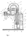
- the SCARA-type robot structure illustrated in particular in FIG. 1, firstly comprises a frame generally designated by the reference 2, capable of being placed on a working support, which is the occurrence a table 4 whose upper surface is horizontal in the example shown.
- This frame 2 is equipped with a protective cover 6, inside which is provided a foot 8, whose base 10 rests directly on the aforesaid table 4.
- This foot 8 initially supports a first motor 12, having a rotary axis 12 1 , pivotable about a vertical axis, which is adapted to cooperate with a belt 14, of a type known per se.
- the latter is adapted to drive a ring gear 16, the corresponding reduction depending on the ratio of teeth between the output of the motor 12 and the ring 16.
- This ring 16 is also integral with a bushing 18, called slideway, whose inner surface is provided with unrepresented balls, which are arranged axially, with reference to the main axis Z of a shaft which will be described in more detail in the following.
- this Z axis is vertical, namely perpendicular to the plane of the table 4.
- This slide sleeve 18 is guided in rotation, while being locked in translation, in a bearing 20 of the ball bearing type, which is of classical structure.
- the foot supports a second motor 22, also having a rotary axis 22 1 , adapted to pivot about a vertical axis.
- This motor 22 cooperates with a second belt 24, adapted to drive a second ring gear 26.
- the latter is secured to a second ball-type bushing 28, nut-type, whose inner surface is provided with balls, which are arranged so helical around the aforementioned Z axis.
- a hollow shaft 32 forming a displacement member as will be seen in what follows, is received in the interior volume of the frame 2.
- This shaft 32 which is placed vertically in use, extends outside the frame 2 through an opening 34 formed in the upper wall of the hood 6.
- the outer surface of the shaft 32 is hollowed with longitudinal grooves, for example three in number, which extend over a major part of the axial dimension of this shaft.
- This outer surface is further hollowed with a helical groove, extending at least in the upper part of the shaft 32, so as to cooperate with the nut sleeve 28.
- These grooves, respectively longitudinal and helical, which are not shown in the figures, are produced in a manner known per se, for example according to the embodiment of the shaft illustrated in FIG. EP-A-1,525,957 .
- the upper end of the shaft 32 is integral with the body 42 of a first arm 40, movable relative to the frame as will be seen in more detail in the following.
- This arm 40 is provided with a protective cover 44, while a bellows 46, expandable and retractable, seals between the first arm 40 and the frame 2, particularly with respect to external dust that may alter the operation of the sockets 18 and 28.
- This bellows 46 is also likely to improve the safety of use of the entire robot. Note that this bellows can be replaced by a system ensuring a high degree of tightness, compatible with cleanroom applications.
- the arm 40 is also provided with a motor 48, having a rotary axis 48 1 , pivotally mounted about a vertical axis, which drives via a belt 50 an additional shaft 52.
- the latter has a main axis Z ', parallel to that Z of the shaft 32 while being offset with respect to this last axis.
- the additional shaft 52 is integral with the body 62 of a second arm 60, also provided with a protective cover 64.
- This arm 60 is provided with a motor 66, having a rotary axis 66 1 , pivotable about a vertical axis, which drives via a belt 68 a member 70 for receiving a tool 72, which is provided with the robot according to the invention.
- This receiving member 70 of conventional type, is a flange in the illustrated example, while the tool 72 is for example a gripper or a grinding tool. It will be noted that, thanks to the motor 66, the receiving member 70 is able to pivot about an axis Z ", which is parallel to that Z 'of the shaft 52, while being offset with respect to this axis.
- the robot according to the invention also incorporates a harness 80, which is composed in a manner known per se of a set of cables, in particular of the electric or pneumatic type. These cables, which provide power to the various auxiliary elements of the robot, namely including the tool and embedded motors, are surrounded by a protective sheath.
- the harness 80 is received in a guide 82, fixed on the base 10 of the foot 8.
- the harness 80 is slidable through the guide 82, so as to compensate the movements of the arm 40 along the vertical axis Z.
- a reserve cable, belonging to the harness which is fed for example by a mechanical device reel type, in lower part of the building.
- the cables of this harness are also likely to be powered from outside the frame 2, by means not shown, such as a controller of conventional type.
- the harness 80 extends, from the guide 82, inside the hollow shaft 32, so as to penetrate into the interior volume of the first arm 40. Then, this harness describes a loop of about 180 ° and is received inside the additional shaft 52, also hollow, so as to penetrate the interior volume of the second arm 60. Some of the power cables, belonging to the harness 80, are connected to the motors 48 and 66 of the not shown, known per se.
- the tool-specific supply cables are connected thereto via an aperture 83, shown schematically, which is recessed in the receiving flange 70 of the tool. Since the latter is rotated by +/- 360 °, the cables form a winding 84, extending about two turns, which enters the aforementioned opening. This measurement, which is of conventional type, reduces the stresses to which its cables are subjected.
- the tool receiving member 70 is housed in the internal volume of the second arm 60, which is delimited by the protective cover 64.
- the opening 83 ensuring the passage of the power cables in the direction of the tool, is also integrated in this interior volume, which is advantageous in particular in terms of protection of these different cables against external aggression.
- the first arm 40 is movable relative to the frame 2, both in translation along the Z axis and in rotation about this same axis.
- motors 12 and 22 are selectively starting one and / or the other of motors 12 and 22, so as to cause the rotation of one and / or the other of the sockets 18 and 28.
- these motors 12 and 22 meshing with the shaft 32, in order to set it in rotation motion and / or in translation relative to the frame 2.
- the driving ring 16 is secured at its lower end to a bearing, said fixed 102, of known type, for example ball bearing.
- This fixed bearing 102 supports a ring 104, made for example of metal material, which is fixed relative to the bearing 102 in translation along the axis Z, but which is free to rotate relative thereto around the same axis Z.
- This ring 104 has a radially inner inclined surface 104 ', which flares downwards, namely opposite to the ring gear 16.
- the lower end of the shaft 32 is surrounded by a body 106, integral with the foot.
- This body 106 defines a first housing, radially internal, for receiving a spring 109 disposed immediately at the periphery of the shaft 32.
- This body 106 further defines a second housing, radially external, for receiving a coil electromagnetic 110, of a type known per se.
- annular plate 112 At the upper end of the body 106, that is to say turned towards the ring gear 16, there is provided an annular plate 112, capable of being displaced in translation along the axis Z relative to the body 106. This translation can be performed in both directions, as will be seen in the following, depending on whether the plate 112 is moved by the spring 109 or the coil 110.
- This plate 112 receives, at its end opposite the body 106, a second bearing 114, similar to the 102 described above.
- This bearing 114 said mobile, is secured to a second ring 116, similar to that described 104.
- This ring 116 has an inclined surface 116 ', which differs from that 104' in that it flares up, namely in the direction of the ring gear 16.
- this ring 118 is split, in that it does not extend 360 ° around the shaft 32. It is slidably mounted on this shaft 32, so that, in the absence of external action, this ring is not likely to affect the free movement of the tree.
- this ring 118 has two inclined surfaces 118 'and 118 ", which are respectively conjugate to that 104' of the ring 104 and 116 'of the ring 116. In other words, these two inclined surfaces 118 'and 118' affect, in longitudinal section, a chevron shape.
- FIG. 2A illustrates on a larger scale a normal operating position, for which it is not necessary to brake the shaft with respect to a translation along the Z axis.
- the coil 110 is activated. so that the plate 112, made of a suitable material, is pressed against this coil 110 and that the rings 104 and 116 are placed at a distance from the split intermediate ring 118.
- this shaft 32 If it is desired to brake this shaft 32, it is to disable the coil 110, so that the spring 109 pushes the plate 112, the bearing 114 and the ring 116 opposite the coil. There is then a clearance, noted j 2 , between the coil 110 and the plate 112. Under these conditions, this ring 116 is close to the fixed ring 104, so that it tends to jam the intermediate ring 118 against this fixed ring 104. Note that, in case of inadvertent power failure, the intermediate ring 118 is also stuck, which is advantageous in terms of safety since the main shaft and the two arms of the structure do not fall back under the effect of gravity.
- These braking means which include in particular the three rings 104, 116 and 118 described above, and allow to block the translation of the shaft 32 along the Z axis, while continuing to allow the rotation of this shaft around this same axis. Under these conditions, it is possible to perform a learning operation of the robot structure of the invention, since the two arms 40 and 60 can be moved in rotation relative to the frame 2.
- the fact that the shaft is locked in translation is advantageous, in particular insofar as it is not necessary for the operator to support the shaft 32, as well as the two arms 40 and 60, to the against gravity.
- the braking system described above is incorporated, not in the lower part of the frame, but in an intermediate zone located for example between the two sockets 18 and 28.
- FIGS. 3, 3A and 3B An additional variant of the braking means, explained above, will now be described with reference to FIGS. 3, 3A and 3B.
- the mechanical elements similar to those of Figure 1 are assigned the same reference numbers, increased by 200.
- the body 206 integral with the frame, in which is received an electromagnetic coil 210.
- the slide sleeve 218, and its ring gear 216 and its guide bearing 220 differ from those 16, 18 and 20 described in Figure 1, in that they are able to move in translation along the Z axis. Such a displacement has a small amplitude, of the order of a few tenths of a millimeter.
- the guide bearing 220 is mounted in the foot 208 with a sliding fit, allowing the aforementioned displacement while not disturbing the guide of the pivot shaft of the first arm 40, so as not to affect the accuracy in arm's length of the robot structure.
- the coil 210 is activated so that it attracts the bearing 220, made of a suitable material, against a compression spring 209, mounted around the shaft 232 similarly to the spring 109 described above.
- the socket slide 218 is spaced axially from the nut bushing 228, forming a set noted 3 , so that they are not mutually connected. The different movements of the shaft 232, both in rotation and in translation, are therefore permitted.
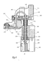
- FIG 4 illustrates an alternative embodiment of the invention.
- the mechanical elements similar to those in Figure 1 are assigned the same reference numbers, increased by 300.
- FIG. 4 differs from that of the preceding figures, in particular in that the frame 302 is provided with a single motor 322, of the same structure as that 22 of FIG. 1.
- This motor 322, which has an axis rotary 322 1 is associated with a belt 324, a ring gear 326, a nut bushing 328, and a bearing 330.
- This second embodiment also differs from the first embodiment, in that the shaft 332 is integral with the first arm 340 only in translation along the axis Z. Thus, this first arm 340 is able to pivot relative to this shaft 332. around this axis Z.
- this first arm 340 is provided with a motor 312 of the same structure as that fitted to the frame 2 of FIG. 1.
- This motor 312 which has a rotary axis 312 1 , is associated with a belt 314, which is adapted to mesh with a ring gear 316, integral with the shaft 332.
- the frame 302 is provided with a ball slide 335, of a type known per se, which is integral with this frame.
- the latter which is intended to prevent the rotation of the shaft 332 about the Z axis, is provided with unrepresented balls, which are adapted to penetrate into the or each longitudinal groove of the shaft 332.
- the second arm 360 and the receiving member of the tool 370 are similar to those described with reference to the first embodiment. In a way similar, we find the same mechanical elements, ensuring the rotation of the second arm 360 relative to the first arm 340, and the receiving member of the tool 370 relative to the second arm 360.
- a motor 348 is provided for driving the second arm 360 in rotation around the axis Z '. It should be emphasized that this motor 348 and the motor 312, intended to drive the rotation of the first arm 340 about the Z axis, are arranged on either side of the shaft 332. This measurement is advantageous, given that it allows to balance the general structure of the first arm 340.
- the operation of the robot structure is as follows.
- the motor 322 is adapted to drive the bushing 328, so as to impart a translational movement, along the Z axis, to the shaft 332. It will be recalled that, due to the presence of the slide 335, any rotation of this shaft 332 relative to frame 302 is prevented.
- the motor 312 when the motor 312 is actuated, the latter cooperates, via the belt 314, with the ring gear 316. Since the latter is secured to the shaft 332, itself linked in rotation with respect to the frame, the motor 312 is then constrained to pivot relative to the shaft 332, which induces the corresponding rotation of the first arm 340 around this shaft 332. Finally, the braking of the shaft, with respect to a translation according to the Z axis, is operated by acting directly on the motor 322, namely by stopping the latter.
- the Z axis is considered to be the direction of gravity. However, it can be expected that this is a another axis taken in space, as for the other axes Z 'and Z "Similarly, the various rotary axes of the motors may not extend vertically, unlike the embodiments of the examples illustrated.
- the position of the two sockets 18 and 28 could be interchanged, without modifying the operating principle of the robot structure according to the invention.
- the first arm 40 or 340 is disposed above the second arm 60 or 360.
- this second arm may be placed above this first arm.
- the recess of the hollow shaft extends centrally, i.e. in other words, the main axis of this recess corresponds to that of the shaft.
- this recess could be eccentric, namely that the walls of this tree could be asymmetrical in nature.
- the first arm is provided with two motors ensuring its movement relative to the hollow shaft.
- the latter is entirely integral with the frame, both in translation and in rotation.
- the two aforementioned motors, integral with the first arm are then adapted to move in translation and in rotation relative to the fixed shaft, so as to impart the movements of this first arm relative to the frame.
- the first arm is provided with the two aforementioned motors, as well as two sockets similar to those fitted to the frame of the first embodiment.
- the motor associated with the nut sleeve locked in translation relative to the first arm, while the other motor is locked in position.
- the motor associated with the nut sleeve must be actuated, so that this sleeve does not rotate relative to the fixed shaft.
- it is to operate the two motors to obtain a combined movement of translation and rotation of the first arm relative to the frame.
- this third embodiment is capable of integrating braking means, against a translation of the hollow shaft along its main axis.
- these braking means are similar to those described and shown with reference to the first embodiment.
- the motor allowing the rotation of the receiving member of the tool, relative to the second arm could be integrated with the first arm.
- a transmission system extending from the first arm to the second arm, while passing for example by the additional hollow shaft connecting these two arms.
- the robot structure of the invention involves two arms, and a receiving member of the movable tool relative to the second arm.
- it can be provided to use a single arm, or to provide that the tool is fixed relative to the second arm.
- the invention achieves the previously mentioned objectives.
- the invention uses a hollow member which provides a dual function, namely on the one hand the protection of the harness supply son and, secondly, the movement of the first arm relative to the frame. This therefore ensures a simplification of the overall structure of the robot, while providing satisfactory protection to this harness.
- the invention is first of all advantageous, insofar as it takes advantage of a relatively small number of onboard engines. These, which are integral with the moving parts of the robot structure, are indeed likely to penalize the performance of this robot, especially in the case where they are fixed on the second arm. This advantageous characteristic is particularly notable in the case of the first embodiment.
- the presence of a small number of onboard engines ensures a reduction in the number of moving cables. Moreover, this is accompanied by a reduction the diameter of the sheath of the harness, which allows a more pronounced curvature thereof.
- this hollow displacement member protects the harness against external aggression, since this harness extends into the overall interior volume of the robot structure.
- the invention has an additional advantage, particularly with respect to the teaching of EP-A-1,525,957 .
- the robot structure of the invention has a large work area, particularly in comparison with the teaching of US Patent 6,199,444 . Indeed, the arrangement of the invention overcomes the presence of an intermediate column, likely to restrict the size of this work area. Note that, in the case where the dimensions of the hollow displacement shaft allow to arrange the second arm above the foot, the pivoting of the first arm is likely to operate over 360 °, which allows to enlarge still this work area.
Landscapes
- Engineering & Computer Science (AREA)
- Robotics (AREA)
- Mechanical Engineering (AREA)
- Manipulator (AREA)
Abstract
Description
La présente invention concerne une structure de robot de type SCARA, ainsi qu'un robot de type SCARA pourvu d'une telle structure.The present invention relates to a robot structure of the SCARA type, as well as to an SCARA type robot provided with such a structure.
De façon classique un robot de type SCARA, ou « Selective Compliance Assembly Robot Arm », comprend tout d'abord un bâti fixe, susceptible par exemple d'être posé sur une table. Il est en outre prévu un bras mobile par rapport au bâti, au moins en rotation, notamment autour d'un axe vertical.Conventionally a robot type SCARA or "Selective Compliance Robot Arm Assembly" comprises first a fixed frame, for example likely to be placed on a table. There is further provided an arm movable relative to the frame, at least in rotation, especially around a vertical axis.
Enfin, ce robot est équipé d'un organe, tel une bride, qui permet la réception d'un outil, qui est par exemple une pince de préhension ou un outil de meulage. Cet organe de réception de l'outil est mobile par rapport au bras précité. Ainsi, il peut tout d'abord être monté directement sur ce bras, avec possibilité de rotation.Finally, this robot is equipped with a member, such as a flange, which allows the reception of a tool, which is for example a gripper or a grinding tool. This receiving member of the tool is movable relative to the aforementioned arm. Thus, it can first be mounted directly on this arm, with the possibility of rotation.
A titre d'alternative, l'organe de réception de l'outil peut être monté sur un bras auxiliaire, qui est lui même libre en rotation par rapport au premier bras. Dans ce dernier cas, l'organe de réception de l'outil peut être fixe, ou bien mobile, par rapport au bras auxiliaire. Enfin, l'organe de réception de l'outil est prévu mobile en translation par rapport au bâti, le plus souvent selon un axe vertical.As an alternative, the receiving member of the tool can be mounted on an auxiliary arm, which is itself free to rotate relative to the first arm. In the latter case, the receiving member of the tool can be fixed or movable relative to the auxiliary arm. Finally, the receiving member of the tool is movable in translation relative to the frame, usually along a vertical axis.
Les robots SCARA, qui présentent de bonnes performances en termes de vitesse, de reproductibilité et de précision, sont utilisés dans de nombreuses opérations industrielles telles que le chargement et le déchargement, ou encore l'assemblage de pièces. Ce type de robot est également avantageux, par comparaison avec d'autres technologies, en ce qu'il se prête de façon aisée à l'opération d'apprentissage. Cette dernière consiste à amener manuellement l'organe de réception de l'outil, appartenant au robot, à un emplacement souhaité, puis à mémoriser cette configuration, plutôt que de la programmer.SCARA robots, which perform well in terms of speed, reproducibility and accuracy, are used in many industrial operations such as loading and unloading, or assembly of parts. This type of robot is also advantageous, in comparison with other technologies, in that it lends itself easily to the learning operation. The latter consists in manually bringing the receiving member of the tool, robot, at a desired location, and then memorize this configuration, rather than programming it.
Afin de faciliter et de sécuriser cette manipulation, il s'agit dans un premier temps, en vue de réaliser cet apprentissage, de bloquer la translation de l'organe de réception de l'outil, tout en autorisant la rotation du premier bras, ainsi que du bras auxiliaire dans l'hypothèse ou ce dernier est présent. On débloque alors, dans un second temps, l'organe de réception de l'outil en translation, ce qui permet de placer cet outil dans sa position appropriée, puis d'enregistrer cette dernière.In order to facilitate and secure this manipulation, it is a first step, in order to achieve this learning, to block the translation of the receiving member of the tool, while allowing the rotation of the first arm, and auxiliary arm in the hypothesis where the latter is present. It is then unlocked, in a second step, the receiving member of the tool in translation, which allows to place this tool in its appropriate position, then to record the latter.
On connaît, par
Cette solution connue présente cependant certains inconvénients, liés en particulier à son encombrement important. Ainsi, la présence des deux moteurs dans le second bras, qui sont placés l'un au-dessus de l'autre, implique que ce second bras présente un encombrement substantiel, selon un axe vertical. Par ailleurs, l'arbre de réception de l'outil, monté sur ce second bras, fait nécessairement saillie par rapport à celui-ci, selon ce même axe. Enfin, il convient de tenir compte de la course de cet arbre, selon cette direction verticale.This known solution, however, has certain disadvantages, particularly related to its large size. Thus, the presence of the two motors in the second arm, which are placed one above the other, implies that the second arm has a substantial size, along a vertical axis. Moreover, the receiving shaft of the tool, mounted on the second arm, necessarily protrudes relative thereto along the same axis. Finally, it is advisable to take into account the race of this tree, according to this vertical direction.
Ces différentes raisons impliquent que le robot décrit dans
Par ailleurs, dans l'agencement décrit dans
Ce harnais, qui est protégé uniquement par une gaine, se trouve rapidement altéré dans la mesure où il est sujet à des arrachements, à une usure prématurée lors des mouvements du robot, ainsi qu'à des détériorations potentielles lorsque le robot est placé dans des atmosphères de travail agressives, par exemple corrosives ou riches en poussière. Par ailleurs, l'existence d'un harnais extérieur au capot est désavantageuse en termes d'encombrement, puisque la position du harnais est variable en fonction des mouvements du robot, de sorte que l'encombrement global de ce dernier est aléatoire.This harness, which is protected only by a sheath, is quickly altered to the extent that it is subject to tearing, premature wear during the movements of the robot, as well as potential damage when the robot is placed in aggressive working atmospheres, eg corrosive or dusty. Moreover, the existence of a harness outside the hood is disadvantageous in terms of space, since the position of the harness is variable depending on the movements of the robot, so that the overall size of the latter is random.
Enfin, on notera que le second bras est équipé de trois moteurs, ainsi que des transmissions qui leurs sont associées. Ceci implique que ce second bras présente un volume nécessairement important, ainsi qu'une inertie élevée, qui est désavantageuse en termes de performances.Finally, it should be noted that the second arm is equipped with three motors, as well as transmissions associated with them. This implies that this second arm has a necessarily large volume and a high inertia, which is disadvantageous in terms of performance.
On connaît également, par
En outre, un premier bras est monté mobile en rotation par rapport à celle colonne, alors qu'il est prévu un second bras, mobile en rotation par rapport à ce premier bras, ce second bras étant lui-même pourvu d'un organe de réception d'un outil, monté rotatif.In addition, a first arm is rotatably mounted relative to the column, while there is provided a second arm, rotatable relative to the first arm, the second arm being itself provided with a body member. receiving a tool, rotatably mounted.
Cette solution alternative résout, dans une certaine mesure, le problème d'encombrement lié à l'enseignement de
Cependant,
De plus, le robot décrit dans ce brevet américain n'est pas propre à couvrir une aire de travail de grande dimension. En effet, la présence de la colonne mobile implique que la rotation du premier bras se trouve rapidement limitée par la présence du bâti, de sorte que les mouvements du robot ne possèdent pas une grande amplitude.In addition, the robot described in this US patent is not suitable for covering a large work area. Indeed, the presence of the movable column implies that the rotation of the first arm is quickly limited by the presence of the frame, so that the movements of the robot do not have a large amplitude.
Enfin, on connaît des robots de type SCARA, décrits par exemple dans
L'enseignement de ces documents permet par conséquent de résoudre, dans une certaine mesure, le problème du harnais de fils d'alimentation. En revanche, la solution qu'ils décrivent présente des inconvénients liés au nombre élevé d'organes mécaniques nécessaires à la mise en mouvement des bras du robot, qui s'accompagne d'une inertie importante en mouvement ainsi que d'un encombrement substantiel.The teaching of these documents therefore makes it possible to solve, to a certain extent, the problem of the harness of supply wires. On the other hand, the solution that they describe has drawbacks related to the large number of mechanical parts necessary to set the arms of the robot in motion, which is accompanied by inertia. important in motion as well as a substantial footprint.
Ceci étant précisé, l'invention vise à remédier aux différents inconvénients de l'état de la technique évoqués ci-dessus.That being said, the invention aims to remedy the various disadvantages of the state of the art mentioned above.
A cet effet, elle a pour objet une structure de robot de type SCARA, comprenant un bâti, au moins un premier bras mobile par rapport à ce bâti, à la fois en translation selon un axe de déplacement et en rotation autour de ce même axe, des moyens de déplacement de ce premier bras par rapport au bâti, un organe de réception, en particulier une bride ou une broche, d'un outil, notamment une pince de préhension ou un outil de meulage, cet organe de réception de l'outil étant mobile par rapport au premier bras, ainsi qu'un ensemble d'alimentation, en particulier de type électrique et/ou pneumatique, des éléments auxiliaires de ladite structure de robot, une extrémité dudit ensemble d'alimentation étant placée au voisinage de l'organe de réception de l'outil,
caractérisée en ce que les moyens de déplacement comprennent un organe de déplacement creux, qui est mobile en translation selon ledit axe de déplacement par rapport à l'un parmi le bâti et le premier bras, et solidaire en translation par rapport à l'autre parmi le bâti et le premier bras, cet organe de déplacement creux étant mobile en rotation, autour de l'axe de déplacement, par rapport à l'un parmi le bâti et le premier bras, tout en étant solidaire en rotation de l'autre parmi le bâti et le premier bras, et en ce que l'ensemble d'alimentation s'étend, depuis le bâti vers le premier bras, au travers dudit organe de déplacement creux.For this purpose, it relates to a robot structure of the SCARA type, comprising a frame, at least a first movable arm relative to this frame, both in translation along an axis of displacement and in rotation about the same axis. , means for displacing said first arm relative to the frame, a receiving member, in particular a flange or a spindle, of a tool, in particular a gripper or a grinding tool, this receiving member of the tool being movable relative to the first arm, as well as a supply assembly, in particular of electric and / or pneumatic type, auxiliary elements of said robot structure, an end of said supply assembly being placed in the vicinity of the receiving member of the tool,
characterized in that the displacement means comprise a hollow displacement member, which is movable in translation along said axis of displacement with respect to one of the frame and the first arm, and integral in translation relative to the other of the frame and the first arm, this hollow displacement member being rotatable, about the axis of displacement, relative to one of the frame and the first arm, while being integral in rotation with the other of the frame and the first arm, and in that the supply assembly extends from the frame to the first arm, through said hollow displacement member.
L'invention a également pour objet un robot de type SCARA, qui comprend une structure telle que définie ci-dessus, ainsi qu'au moins un outil propre à être rapporté, de façon amovible, sur l'organe de réception de l'outil.The subject of the invention is also a robot of the SCARA type, which comprises a structure as defined above, and at least one clean tool to be reported removably on the receiving member of the tool.
L'invention sera mieux comprise et d'autres avantages de celle-ci apparaîtront plus clairement à la lumière de la description qui va suivre de deux modes de réalisation d'une structure de robot de type SCARA conforme à son principe, donnée uniquement à titre d'exemples non limitatifs et faite en référence aux dessins annexés dans lesquels :
- la figure 1 est une vue en coupe longitudinale d'une structure de robot de type SCARA conforme à l'invention ;
- la figure 2 est une vue en coupe longitudinale, illustrant des moyens de freinage d'un arbre appartenant à la structure de robot de la figure 1 ;
- les figures 2A et 2B sont des vues en coupe longitudinale, analogues à la figure 2 mais à plus grande échelle, illustrant de façon plus précise les moyens de freinage de l'arbre, dans deux positions différentes ;
- la figure 3 est une vue en coupe longitudinale, analogue à la figure 2, illustrant une variante de réalisation des moyens de freinage de l'arbre ;
- les figures 3A et 3B sont des vues en coupe longitudinale, analogues à la figure 3 mais à plus grande échelle, illustrant de façon plus précise les moyens de freinage de l'arbre, dans deux positions différentes ; et
- la figure 4 est une vue en coupe longitudinale, analogue à la figure 1, illustrant une variante de réalisation d'une structure de robot conforme à l'invention.
- Figure 1 is a longitudinal sectional view of a SCARA robot structure according to the invention;
- Figure 2 is a longitudinal sectional view illustrating braking means of a shaft belonging to the robot structure of Figure 1;
- Figures 2A and 2B are views in longitudinal section, similar to Figure 2 but on a larger scale, illustrating more precisely the braking means of the shaft, in two different positions;
- Figure 3 is a longitudinal sectional view, similar to Figure 2, illustrating an alternative embodiment of the braking means of the shaft;
- Figures 3A and 3B are longitudinal sectional views, similar to Figure 3 but on a larger scale, illustrating more precisely the braking means of the shaft, in two different positions; and
- Figure 4 is a longitudinal sectional view, similar to Figure 1, illustrating an alternative embodiment of a robot structure according to the invention.
La structure de robot de type SCARA, illustrée notamment à la figure 1, comprend tout d'abord un bâti désigné dans son ensemble par la référence 2, susceptible d'être disposé sur un support de travail, qui est en l'occurrence une table 4 dont la surface supérieure est horizontale dans l'exemple illustré. Ce bâti 2 est équipé d'un capot de protection 6, à l'intérieur duquel est prévu un pied 8, dont le socle 10 repose directement sur la table précitée 4.The SCARA-type robot structure, illustrated in particular in FIG. 1, firstly comprises a frame generally designated by the
Ce pied 8 supporte tout d'abord un premier moteur 12, possédant un axe rotatif 121, susceptible de pivoter autour d'un axe vertical, qui est propre à coopérer avec une courroie 14, de type connue en soi. Cette dernière est propre à entraîner une couronne dentée 16, la démultiplication correspondante étant fonction du rapport de dents entre la sortie du moteur 12 et cette couronne 16.This
Cette couronne 16 est par ailleurs solidaire d'une douille 18, dite glissière, dont la surface intérieure est munie de billes non représentées, qui sont disposées axialement, en référence à l'axe principal Z d'un arbre qui sera décrit plus en détail dans ce qui suit. Dans le cas d'espèce, cet axe Z est vertical, à savoir perpendiculaire au plan de la table 4. Cette douille glissière 18 se trouve guidée en rotation, tout en étant bloquée en translation, dans un palier 20 de type roulement à billes, qui est de structure classique.This
Au-dessus du premier moteur 12, le pied supporte un second moteur 22, présentant également un axe rotatif 221, propre à pivoter autour d'un axe vertical. Ce moteur 22 coopère avec une seconde courroie 24, propre à entraîner une seconde couronne dentée 26. Cette dernière est solidaire d'une seconde douille à billes 28, de type écrou, dont la surface intérieure est pourvue de billes, qui sont disposées de façon hélicoïdale autour de l'axe Z précité. Un second palier 30, par exemple de type à roulement à billes, qui est fixé sur le pied 8, assure le guidage en rotation, ainsi que le blocage suivant l'axe Z, de cette douille écrou 28.Above the
Un arbre creux 32, formant un organe de déplacement comme on le verra dans ce qui suit, est reçu dans le volume intérieur du bâti 2. Cet arbre 32, qui est placé verticalement en service, s'étend à l'extérieur du bâti 2 au travers d'une ouverture 34, ménagée dans la paroi supérieure du capot 6.A
La surface extérieure de l'arbre 32 est creusée de rainures longitudinales, prévues par exemple au nombre de trois, qui s'étendent sur une majeure partie de la dimension axiale de cet arbre. Cette surface extérieure est en outre creusée d'une rainure hélicoïdale, s'étendant au moins dans la partie supérieure de l'arbre 32, de manière à coopérer avec la douille écrou 28. Ces rainures, respectivement longitudinales et hélicoïdale, qui ne sont pas représentées sur les figures, sont réalisées de façon connue en soi, par exemple conformément au mode de réalisation de l'arbre illustré dans
Enfin, au voisinage de la partie basse de cet arbre, il est prévu des moyens de freinage de ce dernier, à l'égard d'un mouvement de translation selon l'axe Z, qui seront décrits plus en détail dans ce qui suit.Finally, in the vicinity of the lower part of this shaft, there are provided braking means of the latter, with respect to a translational movement along the Z axis, which will be described in more detail in what follows.
L'extrémité supérieure de l'arbre 32 est solidaire du corps 42 d'un premier bras 40, mobile par rapport au bâti comme on le verra plus en détail dans ce qui suit. Ce bras 40 est pourvu d'un capot de protection 44, alors qu'un soufflet 46, extensible et rétractable, assure l'étanchéité entre ce premier bras 40 et le bâti 2, notamment à l'égard des poussières extérieures susceptibles d'altérer le fonctionnement des douilles 18 et 28. Ce soufflet 46 est également de nature à améliorer la sécurité d'utilisation de l'ensemble du robot. On notera que ce soufflet peut être remplacé par un système garantissant un degré d'étanchéité élevé, compatible avec des applications en salle blanche.The upper end of the
Le bras 40 est par ailleurs pourvu d'un moteur 48, présentant un axe rotatif 481, monté pivotant autour d'un axe vertical, qui entraîne via une courroie 50 un arbre supplémentaire 52. Ce dernier présente un axe principal Z', parallèle à celui Z de l'arbre 32 tout en étant décalé par rapport à ce dernier axe.The
L'arbre supplémentaire 52 est solidaire du corps 62 d'un second bras 60, également pourvu d'un capot de protection 64. Ce bras 60 est muni d'un moteur 66, présentant un axe rotatif 661, susceptible de pivoter autour d'un axe vertical, qui entraîne via une courroie 68 un organe 70 de réception d'un outil 72, dont est pourvu le robot conforme à l'invention. Cet organe de réception 70, de type classique, est une bride dans l'exemple illustré, alors que l'outil 72 est par exemple une pince de préhension ou un outil de meulage. On notera que, grâce au moteur 66, l'organe de réception 70 est propre à pivoter autour d'un axe Z", qui est parallèle à celui Z' de l'arbre 52, tout en étant décalé par rapport à cet axe.The
Le robot conforme à l'invention intègre également un harnais 80, qui est composé de façon connue en tant que telle d'un ensemble de câbles, notamment de type électrique ou pneumatique. Ces câbles, qui assurent l'alimentation des différents éléments auxiliaires du robot, à savoir notamment de l'outil et des moteurs embarqués, sont entourés d'une gaine de protection.The robot according to the invention also incorporates a
A son extrémité inférieure, le harnais 80 est reçu dans un guide 82, fixé sur le socle 10 du pied 8. On notera que, selon une variante non représentée, le harnais 80 est susceptible de coulisser au travers du guide 82, de façon à compenser les mouvements du bras 40 selon l'axe vertical Z. On peut également prévoir de constituer une réserve de câbles, appartenant au harnais, qui est alimentée par exemple par un dispositif de mécanique du type dévidoir, en partie basse du bâti. Les câbles de ce harnais sont par ailleurs susceptibles d'être alimentés, depuis l'extérieur du bâti 2, par des moyens non représentés, tels qu'un contrôleur de type classique.At its lower end, the
Le harnais 80 s'étend, à partir du guide 82, à l'intérieur de l'arbre creux 32, de façon à pénétrer dans le volume intérieur du premier bras 40. Puis, ce harnais décrit une boucle d'environ 180° et se trouve reçu à l'intérieur de l'arbre supplémentaire 52, également creux, de manière à pénétrer dans le volume intérieur du second bras 60. Certains des câbles d'alimentation, appartenant au harnais 80, sont connectés aux moteurs 48 et 66 d'une manière non représentée, connue en soi.The
De plus, les câbles d'alimentation spécifiques à l'outil sont connectés à ce dernier par l'intermédiaire d'une ouverture 83, représentée de façon schématique, qui est creusée dans la bride de réception 70 de l'outil. Etant donné que cette dernière est soumise à une rotation de +/- 360°, les câbles forment un enroulement 84, s'étendant sur environ deux tours, qui pénètre dans l'ouverture précitée. Cette mesure, qui est de type classique, permet de réduire les sollicitations auxquelles sont soumis ses câbles.In addition, the tool-specific supply cables are connected thereto via an
On notera que l'organe 70 de réception de l'outil est logé dans le volume intérieur du second bras 60, qui est délimité par le capot de protection 64. L'ouverture 83, assurant le passage des câbles d'alimentation en direction de l'outil, est également intégrée dans ce volume intérieur, ce qui est avantageux notamment en termes de protection de ces différents câbles à l'égard des agressions extérieures.Note that the
En service, le premier bras 40 est mobile par rapport au bâti 2, à la fois en translation selon l'axe Z et en rotation autour de ce même axe. A cet effet, il s'agit de mettre en marche sélectivement l'un et/ou l'autre des moteurs 12 et 22, de manière à provoquer la rotation de l'une et/ou l'autre des douilles 18 et 28. Ainsi, ces moteurs 12 et 22 engrènent avec l'arbre 32, en vue de sa mise en mouvement en rotation et/ou en translation par rapport au bâti 2.In use, the
De façon plus précise, si l'on désire conférer à l'arbre un mouvement de translation pure, il s'agit d'actionner uniquement le moteur supérieur 22, l'autre moteur 12 étant bloqué en position, de façon à entraîner en rotation la douille à écrou 28. Le mouvement de rotation de cette douille 28, dont on rappelle qu'elle est bloquée en translation suivant l'axe Z, induit alors la translation de l'arbre 32 selon cet axe Z. De plus, si l'on désire conférer à l'arbre 32 un mouvement de rotation pure, il s'agit d'entraîner les deux douilles 18 et 28 dans le même sens de rotation, à la même vitesse de rotation.More specifically, if it is desired to give the shaft a pure translational movement, it is only to actuate the
Enfin, si l'on désire conférer un mouvement combiné de translation et de rotation à l'arbre 32, il s'agit d'entraîner les deux douilles 18 et 28 à des vitesses de rotation différentes. Dans cette optique, on peut également entraîner ces moteurs selon des sens de rotation contraires, en fonction de la nature du mouvement que l'on désire impartir à l'arbre 32.Finally, if it is desired to confer a combined movement of translation and rotation to the
Etant donné que, comme on l'a vu ci-dessus, l'arbre 32 est fixe par rapport au corps 42 du premier bras 40, cet arbre transmet ainsi à ce bras son mouvement de rotation et/ou de translation. Ainsi, dans la structure de robot SCARA décrite ci-dessus, non seulement l'outil 72, mais également les deux bras 40 et 60 sont mobiles en translation selon l'axe Z, par rapport au bâti 2.Since, as seen above, the
On va maintenant décrire, dans ce qui suit, une première variante de réalisation des moyens de freinage de l'arbre, à l'égard d'un mouvement de translation selon l'axe Z. Comme l'illustrent les figures 2, 2A et 2B, la couronne d'entraînement 16 est solidaire à son extrémité inférieure d'un palier, dit fixe 102, de type connu en soi, par exemple à roulement à billes. Ce palier fixe 102 supporte une bague 104, réalisée par exemple en matière métallique, qui est fixe par rapport au palier 102 en translation selon l'axe Z, mais qui est libre de tourner par rapport à celui-ci autour du même axe Z. Cette bague 104 présente une surface radiale interne inclinée 104', qui s'évase vers le bas, à savoir à l'opposé de la couronne dentée 16.We will now describe, in the following, a first embodiment of the braking means of the shaft, with respect to a translation movement along the axis Z. As illustrated in Figures 2, 2A and 2B, the driving
Par ailleurs, l'extrémité inférieure de l'arbre 32 est entourée par un corps 106, solidaire du pied. Ce corps 106 délimite un premier logement, radialement interne, permettant la réception d'un ressort 109 disposé immédiatement à la périphérie de cet arbre 32. Ce corps 106 définit en outre un second logement, radialement externe, destiné à la réception d'une bobine électromagnétique 110, de type connu en soi.Furthermore, the lower end of the
A l'extrémité supérieure du corps 106, c'est-à-dire tournée vers la couronne dentée 16, il est prévu une plaque annulaire 112, susceptible d'être déplacée en translation selon l'axe Z par rapport à ce corps 106. Cette translation peut être réalisée dans les deux sens, comme on le verra dans ce qui suit, selon que la plaque 112 est mise en mouvement par le ressort 109 ou la bobine 110.At the upper end of the
Cette plaque 112 reçoit, à son extrémité opposée au corps 106, un second palier 114, analogue à celui 102 décrit précédemment. Ce palier 114, dit mobile, est solidaire d'une seconde bague 116, analogue à celle décrite 104. Cette bague 116 possède une surface inclinée 116', qui diffère de celle 104' en ce qu'elle s'évase vers le haut, à savoir en direction de la couronne dentée 16.This
Il est enfin prévu une bague intermédiaire 118, réalisée de préférence en une matière plastique lui conférant des qualités de souplesse. Cette bague 118 est fendue, en ce sens qu'elle ne s'étend pas sur 360° autour de l'arbre 32. Elle est montée glissante sur cet arbre 32, de sorte que, en l'absence d'action extérieure, cette bague n'est pas de nature à affecter le libre déplacement de l'arbre. En coupe longitudinale, cette bague 118 présente deux surfaces inclinées 118' et 118" , qui sont conjuguées respectivement de celle 104' de la bague 104 et de celle 116' de la bague 116. En d'autres termes, ces deux surfaces inclinées 118' et 118" affectent, vues en coupe longitudinale, une forme de chevron.It is finally provided an
La figure 2A illustre à plus grande échelle une position de service normal, pour laquelle il n'est pas nécessaire de freiner l'arbre à l'égard d'une translation selon l'axe Z. Dans ce cas, la bobine 110 est activée de sorte que la plaque 112, réalisée en un matériau approprié, se trouve plaquée contre cette bobine 110 et que les bagues 104 et 116 se trouvent placées à distance de la bague intermédiaire fendue 118. Dans ces conditions, il existe des jeux notés j1 et j'1, à la fois de type axial et radial, entre les différentes surfaces inclinées, respectivement 104' et 118', ainsi que 118" et 116'. Par conséquent, la présence des différentes bagues 104, 116 et 118 n'est pas de nature à empêcher la libre translation de l'arbre 32 selon l'axe Z, ainsi que sa libre rotation autour de cet axe. Sur la figure 2A, ces jeux j1 et j'1 sont accentués pour une meilleure compréhension.FIG. 2A illustrates on a larger scale a normal operating position, for which it is not necessary to brake the shaft with respect to a translation along the Z axis. In this case, the
Si l'on désire freiner cet arbre 32, il s'agit de désactiver la bobine 110, de sorte que le ressort 109 repousse la plaque 112, le palier 114 et la bague 116 à l'opposé de la bobine. Il existe alors un jeu, noté j2, entre la bobine 110 et la plaque 112. Dans ces conditions, cette bague 116 se rapproche de la bague fixe 104, de sorte qu'elle tend à coincer la bague intermédiaire 118 contre cette bague fixe 104. On notera que, en cas de coupure intempestive d'alimentation électrique, cette bague intermédiaire 118 se trouve également coincée, ce qui avantageux en termes de sécurité puisque l'arbre principal et les deux bras de la structure ne retombent pas sous l'effet de la gravité.If it is desired to brake this
De façon plus précise, les surfaces inclinées respectives 104' et 116' des bagues 104 et 116 exercent un effort axial sur les surfaces inclinées 118' et 118'' de la bague intermédiaire 118. Ceci se traduit également par la formation d'une contrainte radiale, dirigée vers l'intérieur, exercée sur cette bague intérieure 118. Par conséquent, cette dernière se resserre, de manière à être solidarisée par adhérence avec l'arbre 32, comme illustré à la figure 2B.More specifically, the respective inclined surfaces 104 'and 116' of the
Dans ces conditions, ce dernier se trouve bloqué en translation, selon l'axe Z, par l'intermédiaire des différentes bagues 104, 116 et 118, qui se trouvent liées en translation par rapport au bâti 2. En revanche, l'arbre 32 est libre de pivoter autour de cet axe Z, du fait de la présence des paliers à roulements 102 et 114, dont les bagues internes ne sont pas montées au contact respectivement de la couronne 16 et de la plaque 112 du fait d'aménagements de formes sur les pièces 16 et 112.Under these conditions, the latter is locked in translation, along the Z axis, through the
Ces moyens de freinage, qui comprennent notamment les trois bagues 104, 116 et 118 décrites ci-dessus, permettent ainsi de bloquer la translation de l'arbre 32 selon l'axe Z, tout en continuant à autoriser la rotation de cet arbre autour de ce même axe. Dans ces conditions, il est possible de réaliser une opération d'apprentissage de la structure de robot de l'invention, étant donné que les deux bras 40 et 60 peuvent être déplacés en rotation par rapport au bâti 2.These braking means, which include in particular the three
Par ailleurs, le fait que l'arbre est bloqué en translation est avantageux, notamment dans la mesure où il n'est pas nécessaire pour l'opérateur de soutenir l'arbre 32, ainsi que les deux bras 40 et 60, à l'encontre de la gravité. A titre de variante non représentée, on peut prévoir que le système de freinage décrit ci-dessus est incorporé, non pas en partie basse du bâti, mais dans une zone intermédiaire située par exemple entre les deux douilles 18 et 28.Furthermore, the fact that the shaft is locked in translation is advantageous, in particular insofar as it is not necessary for the operator to support the
Une variante supplémentaire des moyens de freinage, explicités ci-dessus, va maintenant être décrite en référence aux figures 3, 3A et 3B. Sur ces figures, les éléments mécaniques analogues à ceux de la figure 1 y sont affectés des mêmes numéros de référence, augmentés de 200.An additional variant of the braking means, explained above, will now be described with reference to FIGS. 3, 3A and 3B. In these figures, the mechanical elements similar to those of Figure 1 are assigned the same reference numbers, increased by 200.
Dans cette variante, on retrouve un corps 206, solidaire du bâti, dans lequel est reçue une bobine électromagnétique 210. La douille glissière 218, ainsi que sa couronne dentée 216 et son palier de guidage 220 diffèrent de ceux 16, 18 et 20 décrits à la figure 1, en ce qu'ils sont susceptibles de se déplacer en translation selon l'axe Z. Un tel déplacement présente une faible amplitude, de l'ordre de quelques dixièmes de millimètres. A cet effet, le palier de guidage 220 est monté dans le pied 208 avec un ajustement glissement, autorisant le déplacement précité tout en ne perturbant pas le guidage de l'arbre de pivotement du premier bras 40, afin de ne pas affecter la précision en bout de bras de la structure de robot.In this variant, there is a
En service normal, comme le montre à plus grande échelle la figure 3A, la bobine 210 est activée de sorte qu'elle attire le palier 220, réalisé en matériau approprié, à l'encontre d'un ressort de compression 209, monté autour de l'arbre 232 de façon analogue au ressort 109 décrit ci-dessus. Dans ces conditions, la douille glissière 218 est distante axialement de la douille écrou 228, en formant un jeu noté j3, de sorte qu'elles ne sont pas liées mutuellement. Les différents mouvements de l'arbre 232, à la fois en rotation et en translation, sont donc permis.In normal operation, as shown on a larger scale in FIG. 3A, the
Si l'on désire exercer une action de freinage sur cet arbre 232, il s'agit de stopper l'alimentation de la bobine 210 de sorte que le ressort 209 repousse le palier 220, ainsi que la douille 218 en direction de l'autre douille 228. On note j4 le jeu ainsi créé entre la bobine 210 et le palier 220. Ceci n'a cependant aucune incidence sur la position axiale de l'arbre 232, puisque cette douille glissière 218 est libre en translation par rapport à cet arbre.If it is desired to exert a braking action on this
Au terme de ce mouvement, comme cela est illustré à la figure 3B, la douille glissière 218 vient au contact de la douille écrou 228, de sorte qu'elle en est désormais solidaire en rotation du fait de la friction ainsi générée. Dans ces conditions, ces deux douilles 218 et 228 sont nécessairement entraînées en rotation, dans le même sens et à la même vitesse angulaire. Or, comme on l'a vu ci-dessus, ceci implique que le seul mouvement possible de l'arbre 232 est une rotation autour de l'axe Z, toute translation selon ce même axe Z étant interdite.At the end of this movement, as illustrated in FIG. 3B, the
On notera également que, en cas de coupure intempestive de l'alimentation électrique, les deux douilles 218 et 228 viennent en contact mutuel, ce qui induit leur solidarisation. Ceci est avantageux en termes de sécurité puisque, dans l'occurrence d'une panne, l'arbre principal et les deux bras de la structure ne retombent pas sous l'effet de la gravité.It will also be noted that, in case of inadvertent power failure, the two
La figure 4 illustre une variante de réalisation de l'invention. Sur cette figure, les éléments mécaniques analogues à ceux de la figure 1 sont affectés des mêmes numéros de référence, augmentés de 300.Figure 4 illustrates an alternative embodiment of the invention. In this figure, the mechanical elements similar to those in Figure 1 are assigned the same reference numbers, increased by 300.
Le mode de réalisation de cette figure 4 diffère de celui des figures précédentes, notamment en ce que le bâti 302 est pourvu d'un seul moteur 322, de même structure que celui 22 de la figure 1. Ce moteur 322, qui possède un axe rotatif 3221, est associé à une courroie 324, à une couronne dentée 326, à une douille écrou 328, ainsi qu'à un palier 330.The embodiment of this FIG. 4 differs from that of the preceding figures, in particular in that the
Ce second mode de réalisation diffère en outre du premier mode, en ce que l'arbre 332 est solidaire du premier bras 340 uniquement en translation selon l'axe Z. Ainsi, ce premier bras 340 est propre à pivoter par rapport à cet arbre 332 autour de cet axe Z.This second embodiment also differs from the first embodiment, in that the
A cet effet, ce premier bras 340 est pourvu d'un moteur 312, de même structure que celui 12 équipant le bâti 2 de la figure 1. Ce moteur 312, qui possède un axe rotatif 3121, est associé à une courroie 314, qui est propre à engrener avec une couronne dentée 316, solidaire de l'arbre 332. On retrouve par ailleurs un palier 320, équipant ce premier bras 340, qui guide la rotation de ce premier bras 340 par rapport à l'arbre 332 désormais fixe en rotation.For this purpose, this
On notera également que, au voisinage de l'ouverture supérieure 334, le bâti 302 est pourvu d'une glissière à billes 335, de type connu en soi, qui est solidaire de ce bâti. Cette dernière, qui est destinée à empêcher la rotation de l'arbre 332 autour de l'axe Z, est pourvue de billes non représentées, qui sont propres à pénétrer dans la ou chaque rainure longitudinale de l'arbre 332. Ces rainures longitudinales, analogues à celle 36 de la figure 2, ne sont pas représentées sur la figure 4.It will also be noted that, in the vicinity of the
On notera en outre que le second bras 360 et l'organe de réception de l'outil 370 sont analogues à ceux décrits en référence au premier mode de réalisation. De façon similaire, on retrouve les mêmes éléments mécaniques, assurant la mise en rotation de ce second bras 360 par rapport au premier bras 340, ainsi que de l'organe de réception de l'outil 370 par rapport à ce second bras 360.Note further that the
Il est en particulier prévu un moteur 348, destiné à entraîner le second bras 360 en rotation autour de l'axe Z'. Il est à souligner que ce moteur 348 et le moteur 312, destiné à entraîner la rotation du premier bras 340 autour de l'axe Z, sont disposés de part et d'autre de l'arbre 332. Cette mesure est avantageuse, étant donné qu'elle permet d'équilibrer la structure générale du premier bras 340.In particular, a
Le fonctionnement de la structure de robot, décrite en référence à la figure 4, est le suivant. Le moteur 322 est propre à entraîner la douille 328, de manière à impartir un mouvement de translation, selon l'axe Z, à l'arbre 332. On rappellera que, du fait de la présence de la glissière 335, toute rotation de cet arbre 332 par rapport au bâti 302 est empêchée.The operation of the robot structure, described with reference to Figure 4, is as follows. The
De plus, lorsqu'on actionne le moteur 312, ce dernier coopère, via la courroie 314, avec la couronne dentée 316. Etant donné que cette dernière est solidaire de l'arbre 332, lui-même lié en rotation par rapport au bâti, le moteur 312 est alors astreint à pivoter par rapport à l'arbre 332, ce qui induit la rotation correspondante du premier bras 340 autour de cet arbre 332. Enfin, le freinage de l'arbre, à l'égard d'une translation selon l'axe Z, est opéré en agissant directement sur le moteur 322, à savoir en arrêtant ce dernier.In addition, when the
L'invention n'est pas limitée aux exemples décrits et représentés.The invention is not limited to the examples described and shown.
Ainsi, dans les deux modes de réalisation illustrés, l'axe Z est considéré comme étant la direction de la pesanteur. Cependant, on peut prévoir qu'il s'agit d'un autre axe pris dans l'espace, tout comme pour les autres axes Z' et Z". De façon similaire, les différents axes rotatifs des moteurs pourraient ne pas s'étendre de façon verticale, contrairement aux modes de réalisation des exemples illustrés.Thus, in both illustrated embodiments, the Z axis is considered to be the direction of gravity. However, it can be expected that this is a another axis taken in space, as for the other axes Z 'and Z "Similarly, the various rotary axes of the motors may not extend vertically, unlike the embodiments of the examples illustrated.
Dans le premier mode de réalisation, la position des deux douilles 18 et 28 pourrait être interchangée, sans modifier le principe de fonctionnement de la structure de robot conforme à l'invention.In the first embodiment, the position of the two
Dans les deux exemples de réalisation, le premier bras 40 ou 340 est disposé au-dessus du second bras 60 ou 360. Cependant, à titre de variante, ce second bras peut être placé au-dessus de ce premier bras.In both embodiments, the
Dans les exemples illustrés, l'évidement de l'arbre creux s'étend de manière centrale, à savoir que, en d'autres termes, l'axe principal de cet évidement correspond à celui de l'arbre. Cependant, cet évidement pourrait être excentré, à savoir que les parois de cet arbre pourraient être de nature dissymétrique.In the illustrated examples, the recess of the hollow shaft extends centrally, i.e. in other words, the main axis of this recess corresponds to that of the shaft. However, this recess could be eccentric, namely that the walls of this tree could be asymmetrical in nature.
A titre de variante supplémentaire, non représentée, on peut prévoir que le premier bras est pourvu des deux moteurs assurant sa mise en mouvement par rapport à l'arbre creux. Dans ce cas, ce dernier est entièrement solidaire du bâti, à la fois en translation et en rotation. En service, les deux moteurs précités, solidaires du premier bras, sont alors propres à se déplacer en translation et en rotation par rapport à l'arbre fixe, de manière à impartir les mouvements de ce premier bras par rapport au bâti.As a further variant, not shown, it can be provided that the first arm is provided with two motors ensuring its movement relative to the hollow shaft. In this case, the latter is entirely integral with the frame, both in translation and in rotation. In use, the two aforementioned motors, integral with the first arm, are then adapted to move in translation and in rotation relative to the fixed shaft, so as to impart the movements of this first arm relative to the frame.
De façon plus précise, dans ce troisième mode de réalisation, le premier bras est pourvu des deux moteurs précités, ainsi que de deux douilles similaires à celles équipant le bâti du premier mode de réalisation. En service, si l'on désire déplacer en translation pure le premier bras par rapport à l'arbre fixe et, par conséquent, par rapport au bâti, il s'agit d'entraîner le moteur associé à la douille écrou, bloquée en translation par rapport au premier bras, alors que l'autre moteur est bloqué en position.More precisely, in this third embodiment, the first arm is provided with the two aforementioned motors, as well as two sockets similar to those fitted to the frame of the first embodiment. In use, if it is desired to move in pure translation the first arm relative to the fixed shaft and, therefore, relative to the frame, it is to drive the motor associated with the nut sleeve, locked in translation relative to the first arm, while the other motor is locked in position.
En revanche, si l'on désire conférer un mouvement de rotation pure, on actionne le moteur associé à la douille glissière, qui est bloquée en rotation du fait de sa liaison glissière avec l'arbre, lui-même bloqué en rotation. Par conséquent, ce moteur entre en rotation autour de cette douille glissière, tout comme le premier bras solidaire du moteur précité.On the other hand, if it is desired to impart a pure rotational movement, the motor associated with the slide bushing is actuated, which is locked in rotation because of its sliding connection with the shaft, itself locked in rotation. Consequently, this motor rotates around this slide bushing, just like the first integral arm of the aforementioned motor.
On notera que dans ce cas, comme dans le premier mode de réalisation, le moteur associé à la douille écrou doit être actionné, de manière à ce que cette douille ne tourne pas par rapport à l'arbre fixe. Enfin, de manière similaire au premier mode de réalisation, il s'agit d'actionner les deux moteurs en vue d'obtenir un mouvement combiné de translation et de rotation du premier bras par rapport au bâti.Note that in this case, as in the first embodiment, the motor associated with the nut sleeve must be actuated, so that this sleeve does not rotate relative to the fixed shaft. Finally, similarly to the first embodiment, it is to operate the two motors to obtain a combined movement of translation and rotation of the first arm relative to the frame.
On notera également que ce troisième mode de réalisation est susceptible d'intégrer des moyens de freinage, à l'encontre d'une translation de l'arbre creux selon son axe principal. Dans ce cas, ces moyens de freinage sont analogues à ceux décrits et représentés en référence au premier mode de réalisation.It will also be noted that this third embodiment is capable of integrating braking means, against a translation of the hollow shaft along its main axis. In this case, these braking means are similar to those described and shown with reference to the first embodiment.
A titre de variante supplémentaire, également non représentée, le moteur permettant la rotation de l'organe de réception de l'outil, par rapport au second bras, pourrait être intégré au premier bras. Dans cette optique, on prévoit alors un système de transmission, s'étendant du premier bras vers le second bras, tout en passant par exemple par l'arbre supplémentaire creux reliant ces deux bras.As a further variant, also not shown, the motor allowing the rotation of the receiving member of the tool, relative to the second arm, could be integrated with the first arm. In this view, then provides a transmission system, extending from the first arm to the second arm, while passing for example by the additional hollow shaft connecting these two arms.
Dans les différents exemples, la structure de robot de l'invention fait intervenir deux bras, ainsi qu'un organe de réception de l'outil mobile par rapport au second bras. Cependant, à titre de variante, on peut prévoir de faire appel à un unique bras, ou bien encore prévoir que l'outil est fixe par rapport au second bras.In the various examples, the robot structure of the invention involves two arms, and a receiving member of the movable tool relative to the second arm. However, alternatively, it can be provided to use a single arm, or to provide that the tool is fixed relative to the second arm.
L'invention permet d'atteindre les objectifs précédemment mentionnés.The invention achieves the previously mentioned objectives.
L'invention fait appel à un organe creux qui assure une double fonction, à savoir d'une part la protection du harnais de fils d'alimentation et, d'autre part, le déplacement du premier bras par rapport au bâti. Ceci assure par conséquent une simplification de la structure globale du robot, tout en conférant une protection satisfaisante à ce harnais.The invention uses a hollow member which provides a dual function, namely on the one hand the protection of the harness supply son and, secondly, the movement of the first arm relative to the frame. This therefore ensures a simplification of the overall structure of the robot, while providing satisfactory protection to this harness.
Dans ces conditions, l'invention est tout d'abord avantageuse, dans la mesure où elle tire parti d'un nombre relativement réduit de moteurs embarqués. Ces derniers, qui sont solidaires des parties mobiles de la structure de robot, sont en effet de nature à pénaliser les performances de ce robot, en particulier dans le cas où ils sont fixés sur le second bras. Cette caractéristique avantageuse est tout particulièrement notable dans le cas du premier mode de réalisation.Under these conditions, the invention is first of all advantageous, insofar as it takes advantage of a relatively small number of onboard engines. These, which are integral with the moving parts of the robot structure, are indeed likely to penalize the performance of this robot, especially in the case where they are fixed on the second arm. This advantageous characteristic is particularly notable in the case of the first embodiment.
La diminution du nombre de ces moteurs embarqués présente des avantages spécifiques, puisqu'elle autorise une inertie peu élevée des différents bras. Cette diminution de l'inertie autorise des accélérations supérieures et, par conséquent, des déplacements plus rapides et plus performants de l'ensemble de la structure de robot.The reduction in the number of these onboard engines has specific advantages, since it allows a low inertia of the different arms. This decrease in inertia allows for greater acceleration and, consequently, faster and more efficient movements of the entire robot structure.
De plus, la présence d'un nombre restreint de moteurs embarqués garantit une diminution du nombre de câbles en mouvement. Par ailleurs, ceci s'accompagne d'une réduction du diamètre de la gaine du harnais, qui autorise une courbure plus prononcée de celui-ci.In addition, the presence of a small number of onboard engines ensures a reduction in the number of moving cables. Moreover, this is accompanied by a reduction the diameter of the sheath of the harness, which allows a more pronounced curvature thereof.
En outre, cet organe de déplacement creux permet de protéger le harnais à l'égard des agressions extérieures, puisque ce harnais s'étend dans le volume intérieur global de la structure de robot. Dans ces conditions, l'invention présente un avantage supplémentaire, notamment par rapport à l'enseignement de
Ceci permet également de maîtriser l'encombrement de ce harnais, puisque cet encombrement n'est pas susceptible de varier avec les mouvements du robot, ce qui est avantageux par rapport aux structures de l'état de la technique. Enfin, le passage par l'évidement central de cet arbre permet de minimiser les sollicitations sur le harnais, en service.This also makes it possible to control the bulk of this harness, since this size is not likely to vary with the movements of the robot, which is advantageous compared to the structures of the state of the art. Finally, the passage through the central recess of this tree minimizes the stresses on the harness, in use.
La structure de robot de l'invention possède une aire de travail de dimension importante, en particulier en comparaison avec l'enseignement de
Claims (23)
caractérisée en ce que les moyens de déplacement comprennent un organe de déplacement creux (32 ; 332), qui est mobile en translation selon ledit axe de déplacement (Z) par rapport à l'un parmi le bâti (2 ; 302) et le premier bras (40 ; 340), et solidaire en translation par rapport à l'autre parmi le bâti et le premier bras, cet organe de déplacement creux (32 ; 332) étant mobile en rotation, autour de l'axe de déplacement, par rapport à l'un parmi le bâti (2 ; 302) et le premier bras (40 ; 340), tout en étant solidaire en rotation de l'autre parmi le bâti et le premier bras, et en ce que l'ensemble d'alimentation (80 ; 380) s'étend, depuis le bâti vers le premier bras, au travers dudit organe de déplacement creux (32 ; 332).SCARA-type robot structure, comprising a frame (2; 302), at least one first arm (40; 340) movable relative to this frame, both in translation along an axis of displacement (Z) and in rotation around it of the same axis (Z), means for displacing (12, 22, 32, 312, 322, 332) of this first arm relative to the frame, a receiving member (70, 370), in particular a flange or a spindle, of a tool (72), in particular a gripper or a grinding tool, this tool receiving member being movable relative to the first arm (40; 340), as well as a feed assembly (80; 380), in particular electrical and / or pneumatic type, auxiliary elements (48, 66, 72; 312, 348, 366) of said robot structure, one end of said supply assembly being placed in the vicinity of the receiving member of the tool,
characterized in that the displacement means comprise a hollow displacement member (32; 332), which is movable in translation along said displacement axis (Z) with respect to one of the frame (2; 302) and the first arm (40; 340), and integral in translation with respect to the other of the frame and the first arm, this hollow displacement member (32; 332) being movable in rotation, about the axis of displacement, relative to to one of the frame (2; 302) and the first arm (40; 340), while being rotatably connected to the other of the frame and the first arm, and in that the feed assembly (80; 380) extends from the frame to the first arm through said hollow displacement member (32; 332).
Applications Claiming Priority (1)
| Application Number | Priority Date | Filing Date | Title |
|---|---|---|---|
| FR0603898A FR2900591B1 (en) | 2006-05-02 | 2006-05-02 | STRUCTURE OF SCARA-TYPE ROBOT AND CORRESPONDING ROBOT |
Publications (2)
| Publication Number | Publication Date |
|---|---|
| EP1852225A1 true EP1852225A1 (en) | 2007-11-07 |
| EP1852225B1 EP1852225B1 (en) | 2010-10-20 |
Family
ID=37667624
Family Applications (1)
| Application Number | Title | Priority Date | Filing Date |
|---|---|---|---|
| EP07356057A Active EP1852225B1 (en) | 2006-05-02 | 2007-04-30 | Scara robot structure and corresponding robot |
Country Status (7)
| Country | Link |
|---|---|
| US (1) | US8001868B2 (en) |
| EP (1) | EP1852225B1 (en) |
| JP (1) | JP5269344B2 (en) |
| CN (1) | CN101066590B (en) |
| AT (1) | ATE485135T1 (en) |
| DE (1) | DE602007009892D1 (en) |
| FR (1) | FR2900591B1 (en) |
Cited By (2)
| Publication number | Priority date | Publication date | Assignee | Title |
|---|---|---|---|---|
| WO2013007931A1 (en) | 2011-07-11 | 2013-01-17 | Universite Du Havre | Motor-driven table for micrometric positioning |
| EP2633962A1 (en) | 2012-03-02 | 2013-09-04 | Stäubli Faverges | Articulated structure for a multi-axis robot and robot with such a structure |
Families Citing this family (18)
| Publication number | Priority date | Publication date | Assignee | Title |
|---|---|---|---|---|
| CN102781632B (en) | 2010-03-02 | 2015-06-03 | Abb研究有限公司 | A robot wrist |
| JP5201186B2 (en) * | 2010-09-16 | 2013-06-05 | 株式会社安川電機 | robot |
| CN101983838B (en) * | 2010-10-14 | 2012-07-25 | 复旦大学 | Milling, grinding and polishing device based on intelligent numerically-controlled platform |
| JP5792988B2 (en) * | 2011-04-25 | 2015-10-14 | ヤマハ発動機株式会社 | SCARA robot |
| JP5845061B2 (en) * | 2011-11-07 | 2016-01-20 | ヤマハ発動機株式会社 | Clean robot |
| JP5850089B2 (en) * | 2014-05-13 | 2016-02-03 | セイコーエプソン株式会社 | robot |
| JP2016068200A (en) | 2014-09-30 | 2016-05-09 | セイコーエプソン株式会社 | robot |
| ITUB20159241A1 (en) * | 2015-12-23 | 2017-06-23 | Comau Spa | Multi-axis industrial robot, in particular of the SCARA type |
| JP2018122417A (en) * | 2017-02-02 | 2018-08-09 | セイコーエプソン株式会社 | robot |
| JP6904556B2 (en) * | 2017-02-27 | 2021-07-21 | 株式会社アイエイアイ | SCARA robot |
| CN107671836A (en) * | 2017-10-26 | 2018-02-09 | 上海新时达机器人有限公司 | A kind of plane articulation robot |
| CN107813298A (en) * | 2017-11-24 | 2018-03-20 | 魏传喆 | A kind of medical efficient mechanical hand and its application method |
| US11312006B2 (en) * | 2018-03-30 | 2022-04-26 | Fanuc Corporation | Robot drive unit and robot |
| US10933525B2 (en) * | 2018-07-04 | 2021-03-02 | Fanuc Corporation | Horizontal articulated robot |
| JP6793163B2 (en) * | 2018-09-20 | 2020-12-02 | 本田技研工業株式会社 | Resistance welding equipment |
| JP6923507B2 (en) * | 2018-12-27 | 2021-08-18 | ファナック株式会社 | Robot striatal processing structure |
| US10836052B2 (en) * | 2019-02-06 | 2020-11-17 | Hiwin Technologies Corp. | Connection module using in robot |
| TW202228961A (en) * | 2021-01-27 | 2022-08-01 | 日商發那科股份有限公司 | SCARA robot |
Citations (7)
| Publication number | Priority date | Publication date | Assignee | Title |
|---|---|---|---|---|
| JPS61293791A (en) * | 1985-05-30 | 1986-12-24 | ぺんてる株式会社 | Turning gerar for joint type robot using direct drive motor |
| JPS61293691A (en) | 1985-06-20 | 1986-12-24 | Riken Corp | Welding method by laser |
| EP0937550A1 (en) * | 1997-07-14 | 1999-08-25 | Fanuc Ltd | Industrial robot |
| US6199444B1 (en) | 1998-07-29 | 2001-03-13 | Janome Sewing Machine Co., Ltd. | Robot having multi-joint arms movable in horizontal plane |
| EP1464455A1 (en) | 2001-12-04 | 2004-10-06 | Rorze Corporation | Scalar type robot for carrying flat plate-like object; and flat plate-like object processing system |
| EP1525957A1 (en) | 2003-10-23 | 2005-04-27 | Bosch Rexroth AG | Scara-type robot |
| US20050193854A1 (en) | 2004-03-03 | 2005-09-08 | Kabushiki Kaisha Yaskawa Denki | Cable processor of robot |
Family Cites Families (8)
| Publication number | Priority date | Publication date | Assignee | Title |
|---|---|---|---|---|
| JPS61168478A (en) * | 1985-01-22 | 1986-07-30 | 株式会社三協精機製作所 | Multi-joint robot |
| JPS6362686A (en) * | 1986-08-30 | 1988-03-18 | フアナツク株式会社 | Multi-joint type robot |
| JPS63156676A (en) * | 1986-12-18 | 1988-06-29 | フアナツク株式会社 | Arm structure of horizontal joint type robot |
| JPH01146678A (en) * | 1987-12-02 | 1989-06-08 | Matsushita Electric Ind Co Ltd | Horizontal multi-joint robot |
| JP2509227Y2 (en) * | 1990-06-08 | 1996-08-28 | 大日本スクリーン製造株式会社 | Arm swivel type substrate transfer device |
| JPH0988954A (en) * | 1995-09-29 | 1997-03-31 | Thk Kk | Compound movement driving device |
| JPH1128691A (en) * | 1997-07-09 | 1999-02-02 | Yaskawa Electric Corp | Linear and rotary operating device |
| JP2002307365A (en) * | 2001-04-11 | 2002-10-23 | Aitec:Kk | Arm of scalar robot |
-
2006
- 2006-05-02 FR FR0603898A patent/FR2900591B1/en not_active Expired - Fee Related
-
2007
- 2007-04-30 EP EP07356057A patent/EP1852225B1/en active Active
- 2007-04-30 CN CN200710107144.7A patent/CN101066590B/en active Active
- 2007-04-30 DE DE602007009892T patent/DE602007009892D1/en active Active
- 2007-04-30 AT AT07356057T patent/ATE485135T1/en not_active IP Right Cessation
- 2007-05-01 JP JP2007120501A patent/JP5269344B2/en active Active
- 2007-05-02 US US11/797,361 patent/US8001868B2/en active Active
Patent Citations (7)
| Publication number | Priority date | Publication date | Assignee | Title |
|---|---|---|---|---|
| JPS61293791A (en) * | 1985-05-30 | 1986-12-24 | ぺんてる株式会社 | Turning gerar for joint type robot using direct drive motor |
| JPS61293691A (en) | 1985-06-20 | 1986-12-24 | Riken Corp | Welding method by laser |
| EP0937550A1 (en) * | 1997-07-14 | 1999-08-25 | Fanuc Ltd | Industrial robot |
| US6199444B1 (en) | 1998-07-29 | 2001-03-13 | Janome Sewing Machine Co., Ltd. | Robot having multi-joint arms movable in horizontal plane |
| EP1464455A1 (en) | 2001-12-04 | 2004-10-06 | Rorze Corporation | Scalar type robot for carrying flat plate-like object; and flat plate-like object processing system |
| EP1525957A1 (en) | 2003-10-23 | 2005-04-27 | Bosch Rexroth AG | Scara-type robot |
| US20050193854A1 (en) | 2004-03-03 | 2005-09-08 | Kabushiki Kaisha Yaskawa Denki | Cable processor of robot |
Cited By (4)
| Publication number | Priority date | Publication date | Assignee | Title |
|---|---|---|---|---|
| WO2013007931A1 (en) | 2011-07-11 | 2013-01-17 | Universite Du Havre | Motor-driven table for micrometric positioning |
| EP2633962A1 (en) | 2012-03-02 | 2013-09-04 | Stäubli Faverges | Articulated structure for a multi-axis robot and robot with such a structure |
| FR2987575A1 (en) * | 2012-03-02 | 2013-09-06 | Staubli Sa Ets | ARTICULATED MULTI-AXIS ROBOT STRUCTURE AND ROBOT COMPRISING SUCH A STRUCTURE |
| US9296114B2 (en) | 2012-03-02 | 2016-03-29 | Staubli Faverges | Articulated structure of a multiple-axis robot and robot comprising such a structure |
Also Published As
| Publication number | Publication date |
|---|---|
| FR2900591A1 (en) | 2007-11-09 |
| ATE485135T1 (en) | 2010-11-15 |
| CN101066590A (en) | 2007-11-07 |
| US8001868B2 (en) | 2011-08-23 |
| US20080148895A1 (en) | 2008-06-26 |
| EP1852225B1 (en) | 2010-10-20 |
| DE602007009892D1 (en) | 2010-12-02 |
| CN101066590B (en) | 2013-03-20 |
| FR2900591B1 (en) | 2008-06-20 |
| JP5269344B2 (en) | 2013-08-21 |
| JP2007296631A (en) | 2007-11-15 |
Similar Documents
| Publication | Publication Date | Title |
|---|---|---|
| EP1852225B1 (en) | Scara robot structure and corresponding robot | |
| EP3175146A1 (en) | Torque reducer | |
| EP3227167B1 (en) | Drive device for a trolley or similar | |
| WO2016207516A1 (en) | Portable power tool comprising an epicyclic reduction gear | |
| EP3099572B1 (en) | Rotation-blocking device with simplified structure, and actuator comprising such a device | |
| WO2016062964A1 (en) | Improved vibratory machining device | |
| EP0188164B1 (en) | Steering unit for an automotive vehicle with a fixed central cushion | |
| EP2313812B1 (en) | Movement for a timepiece with an integrated automatic winding device | |
| EP0869858B1 (en) | Machining unit with rotating head | |
| FR3006617A1 (en) | VIBRATION MACHINING DEVICE | |
| EP1178910A1 (en) | Neutral point setting device for steering wheel in particular | |
| EP3048045B1 (en) | Aircraft wheel rotation drive | |
| EP2998835A1 (en) | Data input device and braking means thereof | |
| WO1992021455A1 (en) | Multiple-tool bending head for wire bending machine | |
| FR2875163A1 (en) | CUTTING HEAD FOR MOTORIZED SCISSORS | |
| EP3654109B1 (en) | Timepiece comprising two energy sources | |
| EP3697194B1 (en) | Gearbox and wheeled vehicle provided with such a gearbox | |
| FR2926033A1 (en) | Rotating tool i.e. ratchet wrench, for assembly line, has orientation units and selection unit connected by connection units transforming translation movement of selection unit into pivoting movement of ratchet by orientation units | |
| EP1503482A1 (en) | A brake and an electrical machine fitted with such a brake | |
| FR2783451A1 (en) | ROBOT FOR HANDLING AN OBJECT | |
| EP1125661B1 (en) | Radial drilling device for a lathe | |
| FR3031962A1 (en) | METHOD FOR DRIVING ROTATION OF AN AIRCRAFT WHEEL | |
| EP2909070A1 (en) | Transmission assembly for a self-propelled machine, and machine fitted with such a transmission | |
| CH688715A5 (en) | Grinding machine for finishing moulded workpieces, e.g. watch cases | |
| FR2863325A1 (en) | Driving motor`s rotation movement transmitting device for motor vehicle, has flexible shaft with extreme part having maximum length housed in housing and twisted pyramid trunk geometry extending between base and free end of extreme part |
Legal Events
| Date | Code | Title | Description |
|---|---|---|---|
| PUAI | Public reference made under article 153(3) epc to a published international application that has entered the european phase |
Free format text: ORIGINAL CODE: 0009012 |
|
| AK | Designated contracting states |
Kind code of ref document: A1 Designated state(s): AT BE BG CH CY CZ DE DK EE ES FI FR GB GR HU IE IS IT LI LT LU LV MC MT NL PL PT RO SE SI SK TR |
|
| AX | Request for extension of the european patent |
Extension state: AL BA HR MK YU |
|
| 17P | Request for examination filed |
Effective date: 20080324 |
|
| 17Q | First examination report despatched |
Effective date: 20080428 |
|
| AKX | Designation fees paid |
Designated state(s): AT BE BG CH CY CZ DE DK EE ES FI FR GB GR HU IE IS IT LI LT LU LV MC MT NL PL PT RO SE SI SK TR |
|
| GRAP | Despatch of communication of intention to grant a patent |
Free format text: ORIGINAL CODE: EPIDOSNIGR1 |
|
| GRAS | Grant fee paid |
Free format text: ORIGINAL CODE: EPIDOSNIGR3 |
|
| GRAA | (expected) grant |
Free format text: ORIGINAL CODE: 0009210 |
|
| AK | Designated contracting states |
Kind code of ref document: B1 Designated state(s): AT BE BG CH CY CZ DE DK EE ES FI FR GB GR HU IE IS IT LI LT LU LV MC MT NL PL PT RO SE SI SK TR |
|
| REG | Reference to a national code |
Ref country code: GB Ref legal event code: FG4D Free format text: NOT ENGLISH |
|
| REG | Reference to a national code |
Ref country code: CH Ref legal event code: EP |
|
| REG | Reference to a national code |
Ref country code: IE Ref legal event code: FG4D Free format text: LANGUAGE OF EP DOCUMENT: FRENCH |
|
| REF | Corresponds to: |
Ref document number: 602007009892 Country of ref document: DE Date of ref document: 20101202 Kind code of ref document: P |
|
| REG | Reference to a national code |
Ref country code: SE Ref legal event code: TRGR |
|
| REG | Reference to a national code |
Ref country code: NL Ref legal event code: VDEP Effective date: 20101020 |
|
| LTIE | Lt: invalidation of european patent or patent extension |
Effective date: 20101020 |
|
| PG25 | Lapsed in a contracting state [announced via postgrant information from national office to epo] |
Ref country code: LT Free format text: LAPSE BECAUSE OF FAILURE TO SUBMIT A TRANSLATION OF THE DESCRIPTION OR TO PAY THE FEE WITHIN THE PRESCRIBED TIME-LIMIT Effective date: 20101020 |
|
| REG | Reference to a national code |
Ref country code: IE Ref legal event code: FD4D |
|
| PG25 | Lapsed in a contracting state [announced via postgrant information from national office to epo] |
Ref country code: LV Free format text: LAPSE BECAUSE OF FAILURE TO SUBMIT A TRANSLATION OF THE DESCRIPTION OR TO PAY THE FEE WITHIN THE PRESCRIBED TIME-LIMIT Effective date: 20101020 Ref country code: PT Free format text: LAPSE BECAUSE OF FAILURE TO SUBMIT A TRANSLATION OF THE DESCRIPTION OR TO PAY THE FEE WITHIN THE PRESCRIBED TIME-LIMIT Effective date: 20110221 Ref country code: IS Free format text: LAPSE BECAUSE OF FAILURE TO SUBMIT A TRANSLATION OF THE DESCRIPTION OR TO PAY THE FEE WITHIN THE PRESCRIBED TIME-LIMIT Effective date: 20110220 Ref country code: BG Free format text: LAPSE BECAUSE OF FAILURE TO SUBMIT A TRANSLATION OF THE DESCRIPTION OR TO PAY THE FEE WITHIN THE PRESCRIBED TIME-LIMIT Effective date: 20110120 Ref country code: AT Free format text: LAPSE BECAUSE OF FAILURE TO SUBMIT A TRANSLATION OF THE DESCRIPTION OR TO PAY THE FEE WITHIN THE PRESCRIBED TIME-LIMIT Effective date: 20101020 Ref country code: NL Free format text: LAPSE BECAUSE OF FAILURE TO SUBMIT A TRANSLATION OF THE DESCRIPTION OR TO PAY THE FEE WITHIN THE PRESCRIBED TIME-LIMIT Effective date: 20101020 Ref country code: FI Free format text: LAPSE BECAUSE OF FAILURE TO SUBMIT A TRANSLATION OF THE DESCRIPTION OR TO PAY THE FEE WITHIN THE PRESCRIBED TIME-LIMIT Effective date: 20101020 Ref country code: SI Free format text: LAPSE BECAUSE OF FAILURE TO SUBMIT A TRANSLATION OF THE DESCRIPTION OR TO PAY THE FEE WITHIN THE PRESCRIBED TIME-LIMIT Effective date: 20101020 |
|
| PG25 | Lapsed in a contracting state [announced via postgrant information from national office to epo] |
Ref country code: GR Free format text: LAPSE BECAUSE OF FAILURE TO SUBMIT A TRANSLATION OF THE DESCRIPTION OR TO PAY THE FEE WITHIN THE PRESCRIBED TIME-LIMIT Effective date: 20110121 |
|
| PG25 | Lapsed in a contracting state [announced via postgrant information from national office to epo] |
Ref country code: EE Free format text: LAPSE BECAUSE OF FAILURE TO SUBMIT A TRANSLATION OF THE DESCRIPTION OR TO PAY THE FEE WITHIN THE PRESCRIBED TIME-LIMIT Effective date: 20101020 Ref country code: IE Free format text: LAPSE BECAUSE OF FAILURE TO SUBMIT A TRANSLATION OF THE DESCRIPTION OR TO PAY THE FEE WITHIN THE PRESCRIBED TIME-LIMIT Effective date: 20101020 Ref country code: ES Free format text: LAPSE BECAUSE OF FAILURE TO SUBMIT A TRANSLATION OF THE DESCRIPTION OR TO PAY THE FEE WITHIN THE PRESCRIBED TIME-LIMIT Effective date: 20110131 |
|
| PLBE | No opposition filed within time limit |
Free format text: ORIGINAL CODE: 0009261 |
|
| STAA | Information on the status of an ep patent application or granted ep patent |
Free format text: STATUS: NO OPPOSITION FILED WITHIN TIME LIMIT |
|
| PG25 | Lapsed in a contracting state [announced via postgrant information from national office to epo] |
Ref country code: RO Free format text: LAPSE BECAUSE OF FAILURE TO SUBMIT A TRANSLATION OF THE DESCRIPTION OR TO PAY THE FEE WITHIN THE PRESCRIBED TIME-LIMIT Effective date: 20101020 Ref country code: DK Free format text: LAPSE BECAUSE OF FAILURE TO SUBMIT A TRANSLATION OF THE DESCRIPTION OR TO PAY THE FEE WITHIN THE PRESCRIBED TIME-LIMIT Effective date: 20101020 Ref country code: PL Free format text: LAPSE BECAUSE OF FAILURE TO SUBMIT A TRANSLATION OF THE DESCRIPTION OR TO PAY THE FEE WITHIN THE PRESCRIBED TIME-LIMIT Effective date: 20101020 Ref country code: SK Free format text: LAPSE BECAUSE OF FAILURE TO SUBMIT A TRANSLATION OF THE DESCRIPTION OR TO PAY THE FEE WITHIN THE PRESCRIBED TIME-LIMIT Effective date: 20101020 |
|
| 26N | No opposition filed |
Effective date: 20110721 |
|
| REG | Reference to a national code |
Ref country code: DE Ref legal event code: R097 Ref document number: 602007009892 Country of ref document: DE Effective date: 20110721 |
|
| PG25 | Lapsed in a contracting state [announced via postgrant information from national office to epo] |
Ref country code: MC Free format text: LAPSE BECAUSE OF NON-PAYMENT OF DUE FEES Effective date: 20110430 |
|
| PG25 | Lapsed in a contracting state [announced via postgrant information from national office to epo] |
Ref country code: MT Free format text: LAPSE BECAUSE OF FAILURE TO SUBMIT A TRANSLATION OF THE DESCRIPTION OR TO PAY THE FEE WITHIN THE PRESCRIBED TIME-LIMIT Effective date: 20101020 |
|
| PG25 | Lapsed in a contracting state [announced via postgrant information from national office to epo] |
Ref country code: CY Free format text: LAPSE BECAUSE OF FAILURE TO SUBMIT A TRANSLATION OF THE DESCRIPTION OR TO PAY THE FEE WITHIN THE PRESCRIBED TIME-LIMIT Effective date: 20101020 Ref country code: LU Free format text: LAPSE BECAUSE OF NON-PAYMENT OF DUE FEES Effective date: 20110430 |
|
| PG25 | Lapsed in a contracting state [announced via postgrant information from national office to epo] |
Ref country code: HU Free format text: LAPSE BECAUSE OF FAILURE TO SUBMIT A TRANSLATION OF THE DESCRIPTION OR TO PAY THE FEE WITHIN THE PRESCRIBED TIME-LIMIT Effective date: 20101020 |
|
| REG | Reference to a national code |
Ref country code: FR Ref legal event code: PLFP Year of fee payment: 10 |
|
| REG | Reference to a national code |
Ref country code: FR Ref legal event code: PLFP Year of fee payment: 11 |
|
| REG | Reference to a national code |
Ref country code: FR Ref legal event code: PLFP Year of fee payment: 12 |
|
| PGFP | Annual fee paid to national office [announced via postgrant information from national office to epo] |
Ref country code: GB Payment date: 20240429 Year of fee payment: 18 |
|
| PGFP | Annual fee paid to national office [announced via postgrant information from national office to epo] |
Ref country code: DE Payment date: 20240429 Year of fee payment: 18 |
|
| PGFP | Annual fee paid to national office [announced via postgrant information from national office to epo] |
Ref country code: CH Payment date: 20240501 Year of fee payment: 18 |
|
| PGFP | Annual fee paid to national office [announced via postgrant information from national office to epo] |
Ref country code: CZ Payment date: 20240408 Year of fee payment: 18 |
|
| PGFP | Annual fee paid to national office [announced via postgrant information from national office to epo] |
Ref country code: IT Payment date: 20240422 Year of fee payment: 18 Ref country code: FR Payment date: 20240425 Year of fee payment: 18 |
|
| PGFP | Annual fee paid to national office [announced via postgrant information from national office to epo] |
Ref country code: TR Payment date: 20240408 Year of fee payment: 18 Ref country code: SE Payment date: 20240427 Year of fee payment: 18 Ref country code: BE Payment date: 20240429 Year of fee payment: 18 |