EP1850752B1 - Urodynamische untersuchungssonde - Google Patents
Urodynamische untersuchungssonde Download PDFInfo
- Publication number
- EP1850752B1 EP1850752B1 EP06724834A EP06724834A EP1850752B1 EP 1850752 B1 EP1850752 B1 EP 1850752B1 EP 06724834 A EP06724834 A EP 06724834A EP 06724834 A EP06724834 A EP 06724834A EP 1850752 B1 EP1850752 B1 EP 1850752B1
- Authority
- EP
- European Patent Office
- Prior art keywords
- probe
- tube
- channel
- bladder
- urethral
- Prior art date
- Legal status (The legal status is an assumption and is not a legal conclusion. Google has not performed a legal analysis and makes no representation as to the accuracy of the status listed.)
- Ceased
Links
- 239000000523 sample Substances 0.000 title claims abstract description 165
- 230000003202 urodynamic effect Effects 0.000 title claims abstract description 25
- 210000003708 urethra Anatomy 0.000 claims abstract description 43
- 239000012530 fluid Substances 0.000 claims description 32
- 238000005259 measurement Methods 0.000 claims description 29
- 229920002614 Polyether block amide Polymers 0.000 claims description 8
- 230000010412 perfusion Effects 0.000 claims description 6
- 229920000139 polyethylene terephthalate Polymers 0.000 claims description 6
- 239000005020 polyethylene terephthalate Substances 0.000 claims description 6
- 229920001971 elastomer Polymers 0.000 claims description 4
- 239000000806 elastomer Substances 0.000 claims description 4
- 229920002635 polyurethane Polymers 0.000 claims description 4
- 239000004814 polyurethane Substances 0.000 claims description 4
- VPRUMANMDWQMNF-UHFFFAOYSA-N phenylethane boronic acid Chemical compound OB(O)CCC1=CC=CC=C1 VPRUMANMDWQMNF-UHFFFAOYSA-N 0.000 claims 1
- 239000004800 polyvinyl chloride Substances 0.000 claims 1
- 229910052710 silicon Inorganic materials 0.000 claims 1
- 239000010703 silicon Substances 0.000 claims 1
- XLYOFNOQVPJJNP-UHFFFAOYSA-N water Substances O XLYOFNOQVPJJNP-UHFFFAOYSA-N 0.000 description 17
- 238000001802 infusion Methods 0.000 description 9
- 238000009530 blood pressure measurement Methods 0.000 description 6
- 238000013016 damping Methods 0.000 description 6
- 238000012360 testing method Methods 0.000 description 6
- 235000019589 hardness Nutrition 0.000 description 4
- 239000000463 material Substances 0.000 description 4
- 229920001296 polysiloxane Polymers 0.000 description 4
- 229920000915 polyvinyl chloride Polymers 0.000 description 3
- 230000004044 response Effects 0.000 description 3
- 210000005070 sphincter Anatomy 0.000 description 3
- 239000004606 Fillers/Extenders Substances 0.000 description 2
- 230000004888 barrier function Effects 0.000 description 2
- 238000004891 communication Methods 0.000 description 2
- JHIVVAPYMSGYDF-UHFFFAOYSA-N cyclohexanone Chemical compound O=C1CCCCC1 JHIVVAPYMSGYDF-UHFFFAOYSA-N 0.000 description 2
- 208000014674 injury Diseases 0.000 description 2
- 238000000034 method Methods 0.000 description 2
- 230000009257 reactivity Effects 0.000 description 2
- 230000002787 reinforcement Effects 0.000 description 2
- 230000003068 static effect Effects 0.000 description 2
- 230000008733 trauma Effects 0.000 description 2
- 230000000472 traumatic effect Effects 0.000 description 2
- 238000011144 upstream manufacturing Methods 0.000 description 2
- -1 Polyethylene terephthalate Polymers 0.000 description 1
- 150000001408 amides Chemical class 0.000 description 1
- 230000008859 change Effects 0.000 description 1
- 230000000295 complement effect Effects 0.000 description 1
- 230000007547 defect Effects 0.000 description 1
- 238000001125 extrusion Methods 0.000 description 1
- 238000001727 in vivo Methods 0.000 description 1
- 238000003780 insertion Methods 0.000 description 1
- 230000037431 insertion Effects 0.000 description 1
- 238000009434 installation Methods 0.000 description 1
- 230000036724 intravesical pressure Effects 0.000 description 1
- 230000007935 neutral effect Effects 0.000 description 1
- 238000004080 punching Methods 0.000 description 1
- 230000035484 reaction time Effects 0.000 description 1
- 238000010079 rubber tapping Methods 0.000 description 1
- 238000007789 sealing Methods 0.000 description 1
- 238000004513 sizing Methods 0.000 description 1
- 239000007787 solid Substances 0.000 description 1
- 230000006641 stabilisation Effects 0.000 description 1
- 238000011105 stabilization Methods 0.000 description 1
- 238000011477 surgical intervention Methods 0.000 description 1
Images


Classifications
-
- A—HUMAN NECESSITIES
- A61—MEDICAL OR VETERINARY SCIENCE; HYGIENE
- A61B—DIAGNOSIS; SURGERY; IDENTIFICATION
- A61B5/00—Measuring for diagnostic purposes; Identification of persons
- A61B5/68—Arrangements of detecting, measuring or recording means, e.g. sensors, in relation to patient
- A61B5/6846—Arrangements of detecting, measuring or recording means, e.g. sensors, in relation to patient specially adapted to be brought in contact with an internal body part, i.e. invasive
- A61B5/6847—Arrangements of detecting, measuring or recording means, e.g. sensors, in relation to patient specially adapted to be brought in contact with an internal body part, i.e. invasive mounted on an invasive device
- A61B5/6852—Catheters
-
- A—HUMAN NECESSITIES
- A61—MEDICAL OR VETERINARY SCIENCE; HYGIENE
- A61B—DIAGNOSIS; SURGERY; IDENTIFICATION
- A61B5/00—Measuring for diagnostic purposes; Identification of persons
- A61B5/20—Measuring for diagnostic purposes; Identification of persons for measuring urological functions restricted to the evaluation of the urinary system
- A61B5/202—Assessing bladder functions, e.g. incontinence assessment
- A61B5/205—Determining bladder or urethral pressure
Definitions
- the invention relates to a urodynamic type urological catheter with a device for performing this examination.
- the urodynamic examination aims to study the dynamic behavior of the bladder and / or the urethra.
- fluid pressure measuring systems have a probe that measures the bladder and urethral pressures.
- the principle of bladder pressure measurement consists of filling the bladder with water and measuring the intravesical pressure.
- Urethral pressure is taken by infusing a fluid at a constant rate through a lateral orifice of a probe inserted into the urethra.
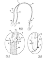
- This probe comprises a distal portion 50 intended to be introduced into the urethra of the patient, and a proximal portion 60 intended to be connected to measuring devices, infusion devices, or other devices used by the doctor, via bases 310, 320.
- the probe here comprises a urethral tube 110 and a bladder tube 120, the bladder tube 120 being intended to take the bladder pressure of the patient, the urethral tube 110 being intended to convey the fluid perfused to achieve a urethral pressure uptake or to convey the fluid to fill the bladder.
- the distal portion 50 comprises the distal portions of the two urethral tubes 110 and bladder 120, the bladder tube 120 extending inside the urethral tube 110, the insertion of the bladder tube 120 into the urethral tube 110 having been performed upstream (at the level of zone 51).
- the distal portion 50 is arranged so that it can be introduced into the patient's urethra and that its end zone 3 can reach the inside of the bladder.
- the space between the bladder tube 120 and the urethral tube 110 (in which the fluid perfused for urethral pressure uptake) is closed at the surface 15 by means of a shutter tube 140.
- the wall of the tube urethral 110 is further provided with eyes 11, 12, 13 and 14 in the vicinity of this end 15.
- FIG 3 which is an enlarged view of zone 3 of the figure 1 , is represented the end zone of the probe.
- the walls of the probe are provided at its end zone 3, with one or more eyes 21, 22, 23 provided for taking the bladder pressure with a fluid present in the bladder tube 120.
- this probe allows a circumferential pressure measurement to the urethral tube 110, distributing homogeneously the pressure on the circumference of the urethra, thus minimizing the losses of the charges for a better examination of the urethra.
- a first step is to fill the bladder through the urethral tube 110 by "lowering" the probe so that the pressure tapping zone (shown on the figure 2 ) is located in the bladder, then “back” the probe so that the pressure setting zone is this time in a certain area of the urethra and then take the urethral pressure in this area.
- the bladder pressure is then taken by means of the bladder tube 120.
- the urodynamic measurements are long and require additional manipulation consisting of disconnecting the urethral tube 110 from the system for bladder filling and then reconnecting it to urethral pressure measuring devices to then take the urethral pressure test.
- this probe does not allow simultaneous urethral pressure and bladder filling, since the urethral tube 110 has the function not only of allowing urethral pressure to be taken, but also of a bladder filling.
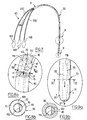
- 5 and 6 is represented another probe of the state of the art (see in particular the document US 5,385,563 ) trying to improve the situation compared to that previously discussed.
- the distal portion 50 consists of a single tube 160 solid provided with a urethral channel 10 and two bladder channels 20 and 30, the two bladder channels 20 and 30 extending to the zone d end of the distal portion 50 of the probe, as shown in FIG. figure 6 which is a sectional view along VI-VI of the figure 4 .
- the two bladder ducts 20 and 30 are respectively provided with eyes 21, 22, 23 and 31, 32, 33 in the end zone of the probe in order respectively to perform bladder filling and bladder pressure for the urodynamic measurement.
- the urethral channel 10 is of a length adapted for infusion of the fluid through it to be possible on an area of the urethra once the probe is in place.
- Extension tubes 210, 220, 230 are then fixed on the respective outputs of the channels 110, 120, 130, in the proximal portion 60 of the probe, to be then connected to measuring and pressure devices (via the bases 310, 320, 330)
- This probe makes it possible to perform simultaneous bladder and urethral pressure measurements, to reduce the measurement time, and to reduce the traumatic risks associated with the friction of the probe against the walls of the urethra.
- urethral fluid uptake is here performed only on a portion of the circumference of the urethra because of the vicinity with the bladder channels 20 and 30 which prevent the provision of eyes from the urethral canal 10 outwards on a significant portion of the circumference of the probe.
- this other probe of the state of the art measures urethral pressures only on a limited circumferential portion of the urethra, and therefore does not allow to account for the reactivity of the urethral surfaces along of the circumference of a given urethral section. This asymmetry or lateralization in the measurements can thus distort the results thereof.
- this configuration increases the risk of disturbance of the measurements due to pressure drop due to a low hydraulic diameter in this type of channel.
- EP 0878166 describes a urodynamic probe that requires the installation of a device for interconnecting fluid sources and sensors on the probe using a flow switch and valves. Nevertheless, these complementary elements induce defects in the measurement of urethral and bladder pressures.
- the probe described in the document GB 2123300 presents several disjointed channels. These channels allow connection of the probe to the sensors and to a fluid source simultaneously. Only one of these channels is dedicated to a measurement of urethral pressure. The presence of these multiple channels makes it impossible to open one of them on the circumference of the probe. Thus the measurement of the urethral pressure can only be made on a limited circumferential portion of the urethra.
- An object of the present invention is to homogeneously distribute the urethral pressure uptake on a circumference of the urethra.
- Another object of the invention is to minimize the problems of pressure drop.
- Another objective is to simultaneously perform a bladder filling and a bladder and urethral pressure measurement.
- Another objective is to minimize the friction of the probe against the walls of the urethra.
- Another objective is to minimize the urodynamic measurement time.
- Another objective is to provide a probe rigid enough to facilitate the introduction of the probe into the urethra, minimize the risk of blockage in the bladder sphincter, and reduce the pressure damping.
- the invention provides, in a first aspect, a probe for urodynamic examination of a patient, comprising a proximal portion, and a distal portion extending longitudinally so as to be housed in the patient's urethra. and for a length sufficient for an end zone to be located in the bladder of the patient, the distal portion comprising three independent internal channels, characterized in that it comprises, in its distal portion, an inner tube and an outer tube at least a portion of the inner tube extending longitudinally in the outer tube so as to define between them a first channel, the other two channels extending into the inner tube.
- the invention proposes an extension of said probe comprising two extension channels able to connect to the end of the proximal portion of the probe, arranged to extend two of said three channels of the probe intended respectively for urethral and bladder measurements, and having been calibrated so that the whole they form with these two channels has the properties described in the two preceding paragraphs.
- the invention proposes a probe assembly consisting of said probe and said extender.
- the proximal portion 60 may consist of three extension tubes 210, 220 and 230 for respectively elongate the channels 10, 20 and 30 of the distal portion of the probe.
- Connection means or bases 310, 320 and 330 may also be provided at the free end of the proximal portion 60 to facilitate the connection of the three extension tubes 210, 220 and 230 with said devices used.
- connection mode (at zone 51 of the figure 7 ) of the three extension tubes 210, 220 and 230 at the end of the three channels 10, 20 and 30 can be achieved by any means known to those skilled in the art.
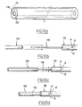
- the wall of the outer tube 110 is provided with one or more eyes 11, 12, 13 and 14 located in the zone 8 so as to communicate the urethral canal 10 with the medium outside the probe (ie the urethra once the probe set up), so that this perfused fluid exerts a pressure capable of serving a urethral measurement during a urodynamic examination.
- a number and a mode of distribution of the eyes 11, 12, 13, 14 are chosen so as to homogeneously distribute the pressure of the fluid on the circumference of the neighboring urethral walls. In this way, it is possible to minimize the pressure drops in the probe and to improve the quality of the measurements.
- the probe comprises means for closing (at the sealing surface 15) the urethral canal 10 in the vicinity of the eyes 11, 12, 13, 14 so that the single output channels for the perfused fluid in the urethral canal 10 are the eyes 11, 12, 13, 14.
- the inner tube 120 is provided with an inner wall 170 extending the entire length of the inner tube 120 and sealingly separating the interior of the inner tube 120 into two portions 20 and 30 defining two bladder channels 20 and 30.
- This internal wall 170 makes it possible in particular to define two channels 20, 30, for a minimum section of the inner tube 120.
- the section of the outer tube 110 is also minimized, and thus allows a probe structure according to the invention can be inserted into the patient's urethra by natural means without surgical intervention and minimizing pain in the patient.
- this inner tube 20 extends away from the proximal portion 60 so as to be sufficiently long, when the probe is placed in position in the urethra, to be able to open into the bladder.
- the first bladder channel 20 thus opens into the bladder via one or more eyes 21, 22 passing through the distal end of the probe in extension of the first bladder channel 20 (ie eye 21 on the bladder). figure 9a ) and / or traversing transversely the longitudinal wall of the end zone 9 of the probe (ie eye 22).
- the second bladder duct 30 opens preferentially through one or more eyes 31 passing through a longitudinal wall of the end zone 9 of the probe.
- the end zone 9 of the probe is arranged so that the only exit route for the fluid perfused into the second bladder canal 30 is the eye 31.
- the distal portion 50 of the probe may, for example, have a mean outside diameter between the carrier 7 and the carrier 12.
- this probe allows a simultaneous measurement of a urethral pressure via a fluid infused into the urethral canal 10, and a bladder pressure via a fluid infused into the second bladder canal 30.
- the particular configuration of the probe according to the invention comprising three channels and two tubes makes it possible to minimize the section of the distal portion 50 of the probe relative to, for example, the case where the three channels 10, 20, 30 have been defined by three different tubes.
- an outer tube 110 and an inner tube 120 are provided so that the section of the outer tube 110 is selected so that the outer tube can be introduced into the urethra of a patient for urodynamic examination.
- the inner diameter of the outer tube 110 and the outer diameter of the inner tube 120 are chosen so that, once the inner tube 120 is threaded into the outer tube 110, a space defined between these two surfaces is sufficient to allow a fluid therein would be infused to circulate at a suitable pressure for urodynamic examination.
- the inner tube 120 comprises an inner wall 170 extending over the entire length and then dividing (as seen previously) two channels vesical interiors 20 and 30.
- This type of tube existing on the market, can for example be obtained by extrusion.
- this inner tube 120 and the disposition of the wall 170 inside this inner tube 120 are chosen so that the second bladder channel 30 can convey a fluid and make it possible to transmit a sufficient bladder static pressure when a urodynamic examination, and so that the first bladder channel 20 has a sufficient section to fill the bladder sufficiently quickly without jolting.
- the eyes 11, 12, 13, 14 are formed in the longitudinal walls of the outer tube 110 located in an area of the tube at which it is desired to carry out the measurements.
- urethral These eyes 11, 12, 13, 14 may be for example made by punching, for example rotatably mounted, or by means of a suitable laser.
- the eyes 11, 12, 13, 14 will be appropriately distributed around the circumference of the outer tube 110 so that, once the probe has been placed in the urethra, the urethral pressure uptake is homogeneously distributed.
- the eyes 11, 12, 13, 14 are four in number, two adjacent eyes can be separated by 90 ° on the circumference of the outer tube 110.
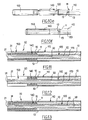
- a length of the outer tube 110 smaller than that of the inner tube 120 so as to leave a small portion of the outer tube 110 beyond the eyes 11, 12, 13, 14, and a remaining portion of the inner tube 120 outgoing (see figure 10b ).
- This tube is then threaded onto the free portion of the inner tube 120 to then congested the free space left between the outer tube 110 and the inner tube 120 until the end of the intermediate tube 140 arrives in the vicinity of the eyes 11, 12, 13, 14.
- the remaining part of the space left between the outer tube 110 and the tube 120 thus closed at one end by the intermediate tube 140, then defines the urethral channel 10.
- the intermediate tube 140 is finally attached to the outer tubes 110 and / or inner 120 by means known to those skilled in the art, such as for example cyclohexanone.
- a terminal tube 150 is chosen whose inner diameter is substantially identical to the outside diameter of the intermediate tube 140, the outside diameter of which is substantially equal to the outside diameter of the outer tube 110, and the length of which is substantially identical to the length of the part of the intermediate tube 140 coming out of the outer tube 110.
- the distal portion 50 of the probe then obtained is represented with reference to the figure 11 after an eye 31 has been made in the wall of the probe to be able to communicate the second bladder channel 30 with the outside in the end zone of the probe.
- this third probe according to the invention does not has no junction between a terminal tube 150 and the tube outside 110, unlike the first two probes according to the invention, which allows to have an outer surface of the probe completely uniform and smooth.
- These three probes according to the invention have in their end part suitable reinforcements (ie intermediate tube 140 and / or end tube 150) which will allow the probe to facilitate its introduction into the urethra, to limit the deformations during its guidance. in the urethra and in the bladder, to be able to pass the natural barriers such as for example the urethral sphincter, and to decrease the damping of the pressures by the probe.
- suitable reinforcements ie intermediate tube 140 and / or end tube 150
- the probe according to the invention is configured, dimensioned so as to improve the comfort for the patient during the urodynamic examination, and in addition to increase the accuracy, the quality of the measurement, as well as the speed and the reactivity of the probe to transmit the measurement.
- the probe is important to dimension the probe so as to avoid overpressures created by a flow in the urethral and bladder channels 30, and thus to reduce the pressure drop in these channels during measurements, for the flow rate values of infusion commonly used (of the order of 0 to 5 ml / min typically for the urethral canal 10 and of the order of 0 ml / min for the second bladder channel 30).
- the pressure drop depends mainly on the flow rate, the internal diameter of the channel considered and the length of the channel considered comprising both the portion of the channel located in the distal portion 50 of the probe and in the proximal portion 60 of the the probe.
- the probes 1 and 2 are also made mainly of PVC, silicone, polyurethane, elastomer, or PET (Polyethylene terephthalate) or PEBA (Polyether Block Amide).
- the proximal side 60 of the probe comprises as shown in the figure 1 , urethral extension tubes 210, and bladder tubes 220 and 230 each connected to the respective outputs of the channels 10, 20 and 30 and each terminating in connection means of the base type 310, 320, 330 respectively for connecting each channel ( urethral, first bladder and second bladder) to a source of fluid and a pressure sensor. These are electrically connected to a recorder not shown. Neutral calibration tests were then carried out by the Applicant to find the configurations and sizing of the probe applying in particular the least pressure losses and a minimum of depreciation.
- the tests consisted of immersing the distal end of the probe in a chamber containing water, then representing the bladder of the patient after filling via the first bladder channel 20, to fill the first bladder channel with water 20 , as well as to communicate the second bladder channel 30 and the urethral channel 10, also filled with water, with the enclosure.
- the urethral canal 10 and possibly the second bladder canal 30 are then perfused at determined flow rates.
- a specific pressure is then exerted on the water contained in the container and the pressure at the proximal end of the urethral 210 and bladder extension tubes 230 is recorded by means of said sensors arranged at their level.
- the probe will be considered as having a loss of load and a damping sufficiently low to be regarded as satisfactory.
- this error is mainly due to losses of loads and the depreciation relative to the probe itself and to the materials of which its tubes are constituted.
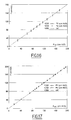
- the Applicant has carried out tests on probes Nos . 1 and 2 mentioned above for pressures exerted on the water contained in the enclosure comprised in the range from 0 to 200 cm 3 of water, for infusion rates in the urethral canal 10 of 1 ml / min and 2 ml / min, and for a perfusion rate of zero in the second bladder canal 30.
- the curves 1000, 1020 and 1030 respectively represent the pressures exerted on the container water, the urethral pressures and the bladder pressures as a function of the reference pressure (i.e. the pressure exerted on the water of the container).
- the Applicant has carried out measurements of the response time of the urethral canal 10, when a specific pressure is applied on the water contained in the chamber.
- the principle is therefore to apply this pressure to the water contained in the chamber for a predetermined time and to measure the time that the urethral channel 10 to transmit 95% of this pressure to its output. Again, measurements were made for Probe 1 and Probe 2
- probes No. 1 and 2 allow response times to 95% urethral lower or about 1 s.
- the relative errors are much less than 5% for the urethral canal 10 and for the second bladder channel 30. They are almost all less than or of the order of 1%.
- the lengths and diameters of the channels according to the invention have been advantageously selected so that the results of these measurements are optimized.
- the probe can also be calibrated in the same way when it is equipped with additional extensions coming to connect at the bases 310, 320, 330, by selecting the diameters and sections of the extensions so as to reduce the damping.
- the materials chosen for the probes such as PVC, silicone, polyurethane, an elastomer, a PET, PEBA (Polyether Block Amide) or any other type of material, as well as the wall thicknesses and their selected hardness, allow to have a satisfactory rigidity while having a fineness of wall, which allows to maintain a relatively small outer diameter.
- the particular configuration of the probe according to the invention in its distal zone 9 makes it possible to obtain rigidity facilitating the introduction of the probe in the urethra, in the passage of the natural biological barrier that is the sphincter vesical, and playing a role in the low damping measured by the Applicant.
Landscapes
- Health & Medical Sciences (AREA)
- Life Sciences & Earth Sciences (AREA)
- Biomedical Technology (AREA)
- Molecular Biology (AREA)
- Veterinary Medicine (AREA)
- Biophysics (AREA)
- Pathology (AREA)
- Engineering & Computer Science (AREA)
- Public Health (AREA)
- Heart & Thoracic Surgery (AREA)
- Medical Informatics (AREA)
- Physics & Mathematics (AREA)
- Surgery (AREA)
- Animal Behavior & Ethology (AREA)
- General Health & Medical Sciences (AREA)
- Physiology (AREA)
- Urology & Nephrology (AREA)
- Measuring And Recording Apparatus For Diagnosis (AREA)
- External Artificial Organs (AREA)
Claims (19)
- Für eine urodynamische Untersuchung eines Patienten vorgesehene Sonde, aufweisend einen proximalen Teil (60) und einen distalen Teil (50), der sich längs erstreckt, um in der Harnröhre des Patienten aufgenommen zu werden, und eine ausreichende Länge hat, so dass eine Endzone in der Harnblase des Patienten angeordnet ist, wobei der distale Teil drei unabhängige innere Kanäle (10,20,30) aufweist, dadurch gekennzeichnet, dass die Sonde in ihrem distalen Teil (50) ein Innenrohr (120) und ein Außenrohr (110) aufweist, wobei sich mindestens ein Teil des Innenrohrs (120) längs in dem Außenrohr (110) erstreckt, um dazwischen einen ersten Kanal (10) zu definieren, wobei sich die zwei anderen Kanäle (20, 30) in dem Innenrohr (120) erstrecken.
- Sonde nach dem vorstehenden Anspruch, dadurch gekennzeichnet, dass die innere Oberfläche des Außenrohrs (110) und die äußere Oberfläche des Innenrohrs (120) im Mittel ausreichend voneinander beabstandet sind, so dass in dem ersten Kanal (10) ein Infusionsfluid bei einem Druck, der geeignet ist, einer urodynamischen Messung zu dienen, zirkulieren kann.
- Sonde nach einem der zwei vorstehenden Ansprüche, dadurch gekennzeichnet, dass das Außenrohr (110) so konstruiert ist, dass in Verwendung der erste Kanal (10) in einer Zone der Harnröhre ausmündet, so dass ein Infusionsfluid in dem ersten Kanal (10) einen Druck auf die Wände der Harnröhre ausüben kann, der geeignet ist, einer urodynamischen Messung zu dienen, und dadurch, dass das Innenrohr (120) so konstruiert ist, dass die zwei anderen Kanäle (20,30) in der Endzone (9) des distalen Teils (50) ausmünden.
- Sonde nach dem vorstehenden Anspruch, dadurch gekennzeichnet, dass der erste Kanal (10) über mindestens ein durch eine Wand des Außenrohrs (110) hindurchgehendes Loch (11,12,13,14) ausmündet.
- Sonde nach Anspruch 3, dadurch gekennzeichnet, dass der erste Kanal (10) über mehrere durch die Wand des Außenrohrs (i10) hindurchgehende Löcher (11,12,13,14) ausmündet, und dadurch, dass diese Löcher so angeordnet sind, um einen Druckabgriff über den gesamten Umfang der Zone der Harnröhre zu verteilen.
- Sonde nach einem der drei vorstehenden Ansprüche, dadurch gekennzeichnet, dass das Innenrohr (120) so konstruiert ist, dass der zweite Kanal (20) ein Fluid transportieren kann, um die Harnblase zu füllen, dadurch, dass der dritte Kanal (30) in der Harnblase ausmünden kann, so dass ein Infusionsfluid in dem dritten Kanal (30) einen Druck auf ein die Harnblase füllendes Fluid ausüben kann, das geeignet ist, einer urodynamischen Messung zu dienen.
- Sonde nach dem vorstehenden Anspruch, dadurch gekennzeichnet, dass der dritte Kanal (30) über mindestens ein durch eine Wand des Innenrohrs (120) hindurchgehendes Loch (31) ausmündet.
- Sonde nach einem der vorstehenden Ansprüche, dadurch gekennzeichnet, dass das Innenrohr (120) eine Innenwand aufweist, die sich längs zu dem Innenrohr (120) erstreckt, um so die zwei anderen Kanäle (20,30) zu definieren.
- Sonde nach einem der zwei vorstehenden Ansprüche, dadurch gekennzeichnet, dass sie außerdem ein Zwischenrohr (140) aufweist, das sich zumindest teilweise zwischen dem Innenrohr (120) und dem Außenrohr (110) erstreckt und ein Ende dessen (15) den ersten Kanal (10) schließt.
- Sonde nach dem vorstehenden Anspruch, dadurch gekennzeichnet, dass sich das Zwischenrohr (140) bis zu dem Ende des Innenrohrs (120) erstreckt.
- Sonde nach dem vorstehenden Anspruch, dadurch gekennzeichnet, dass sich das Außenrohr (110) über einen Teil des Zwischenrohrs (140) erstreckt, und dadurch, dass die Sonde außerdem ein Rohrendstück (150) aufweist, das sich in Verlängerung des Außenrohrs (110) über den anderen Teil des Zwischenrohrs (140) erstreckt.
- Sonde nach Anspruch 10, dadurch gekennzeichnet, dass sich das Außenrohr (110) über das gesamte Zwischenrohr (140) erstreckt.
- Sonde nach Anspruch 9, dadurch gekennzeichnet, dass sich das Zwischenrohr (140) über einen Teil des Innenrohrs (120) erstreckt, dadurch, dass sich das Außenrohr (110) bis zu dem Ende des Zwischenrohrs (140) erstreckt, und dadurch, dass die Sonde ein an dem freien Teil des Innenrohrs (120) angebrachtes Rohrendstück (150) aufweist.
- Sonde nach einem der vorstehenden Ansprüche, dadurch gekennzeichnet, dass der proximale Teil (60) ein Harnröhre-Rohr (210), ein erstes Harnblase-Rohr (220) und ein zweites Harnblase-Rohr (230) aufweist, die jeweils in Verbindung mit dem ersten Kanal (10), dem zweiten Kanal (20) und dem dritten Kanal (30) sind.
- Sonde nach einem der vorstehenden Ansprüche, dadurch gekennzeichnet, dass sie außerdem Anschlussmittel (310,320,330) aufweist, die mit dem Ende des proximalen Teils der Sonde verbunden sind, wobei diese Anschlussmittel vorgesehen sind, um die Sonde an Infusionsgeräte, Geräte für urodynamische Messungen oder andere Vorrichtungen anzuschließen.
- Sonde nach einem der vorstehenden Ansprüche, dadurch gekennzeichnet, dass sie aus PVC, Silikon, Polyurethan, Elastomer, PET oder PEBA ist.
- Sonde nach einem der vorstehenden Ansprüche, dadurch gekennzeichnet, dass ihr distaler Teil (50) einen durchschnittlichen Durchmesser zwischen 7 Charrière und 12 Charrière hat.
- Sonde nach einem der vorstehenden Ansprüche, dadurch gekennzeichnet, dass sie außerdem eine Verlängerungseinrichtung aufweist, die zwei mit dem Ende des proximalen Teils (60) zu verbindende Verlängerungskanäle aufweist, die dazu dienen, zwei der drei Kanäle der Sonde zu verlängern, die jeweils für Harnröhre- und Harnblase-Messungen vorgesehen sind.
- Sonde nach dem vorstehenden Anspruch, dadurch gekennzeichnet, dass die Verlängerungseinrichtung einen dritten Verlängerungskanal aufweist, der von den vorstehend erwähnten zwei Kanälen unabhängig ist und mit dem Ende des proximalen Teils des dritten Kanals verbunden werden kann.
Applications Claiming Priority (2)
| Application Number | Priority Date | Filing Date | Title |
|---|---|---|---|
| FR0501246A FR2881658B1 (fr) | 2005-02-08 | 2005-02-08 | Sonde pour examen urodynamique |
| PCT/EP2006/050651 WO2006084824A1 (fr) | 2005-02-08 | 2006-02-03 | Sonde pour examen urodynamique |
Publications (2)
| Publication Number | Publication Date |
|---|---|
| EP1850752A1 EP1850752A1 (de) | 2007-11-07 |
| EP1850752B1 true EP1850752B1 (de) | 2011-04-06 |
Family
ID=34955504
Family Applications (1)
| Application Number | Title | Priority Date | Filing Date |
|---|---|---|---|
| EP06724834A Ceased EP1850752B1 (de) | 2005-02-08 | 2006-02-03 | Urodynamische untersuchungssonde |
Country Status (4)
| Country | Link |
|---|---|
| EP (1) | EP1850752B1 (de) |
| DE (1) | DE602006021145D1 (de) |
| FR (1) | FR2881658B1 (de) |
| WO (1) | WO2006084824A1 (de) |
Family Cites Families (4)
| Publication number | Priority date | Publication date | Assignee | Title |
|---|---|---|---|---|
| US4073287A (en) * | 1976-04-05 | 1978-02-14 | American Medical Systems, Inc. | Urethral profilometry catheter |
| CA1176929A (en) * | 1982-07-14 | 1984-10-30 | Urotek Inc. | Urodynamic catheter |
| FR2763235B1 (fr) * | 1997-05-15 | 1999-06-25 | Vermed Lab | Dispositif pour examen urodynamique et elements le composant |
| KR100517820B1 (ko) * | 2003-04-07 | 2005-09-29 | 주식회사 에이치엠티 | 실시간 양방향 데이터 검증 방법 및 장치 |
-
2005
- 2005-02-08 FR FR0501246A patent/FR2881658B1/fr not_active Expired - Fee Related
-
2006
- 2006-02-03 EP EP06724834A patent/EP1850752B1/de not_active Ceased
- 2006-02-03 DE DE602006021145T patent/DE602006021145D1/de not_active Expired - Lifetime
- 2006-02-03 WO PCT/EP2006/050651 patent/WO2006084824A1/fr not_active Ceased
Also Published As
| Publication number | Publication date |
|---|---|
| FR2881658A1 (fr) | 2006-08-11 |
| WO2006084824A1 (fr) | 2006-08-17 |
| DE602006021145D1 (de) | 2011-05-19 |
| EP1850752A1 (de) | 2007-11-07 |
| FR2881658B1 (fr) | 2007-04-27 |
Similar Documents
| Publication | Publication Date | Title |
|---|---|---|
| EP0621793B1 (de) | Dilatationskatheter | |
| FR2703592A1 (fr) | Cathéter à ballonnet du type enfilé. | |
| CH615819A5 (de) | ||
| EP1027091B1 (de) | Universalkatheter | |
| EP1070466A2 (de) | Vorrichtung zum Aufbewahren und Auftragen eines Produktes auf Wimpern oder Augenbrauen | |
| FR2920675A1 (fr) | Systeme de pipetage multicanaux comprenant un porte-pistons a guidage ameliore | |
| FR2569615A1 (fr) | Instrument d'ecriture | |
| FR2530149A1 (fr) | Catheter uretral destine notamment aux examens cystometriques | |
| EP2136676A2 (de) | Vorrichtung und vorrichtungssatz mit doppeltem tank für den einsatz im mund, patrone, tank und dazugehöriges herstellungs- und montageverfahren | |
| WO2013186289A1 (fr) | Dispositif d'injection d'un produit liquide comprenant deux demi-coques mobiles en rotation l'une par rapport a l'autre | |
| WO2004058331A1 (fr) | Dispositif de distribution pour un reseau d’acheminement de fluides medicaux vers un patient | |
| EP1850752B1 (de) | Urodynamische untersuchungssonde | |
| EP0748241A1 (de) | Schnelles dilatationskatheter-austauschsystem | |
| EP0762855B1 (de) | Zahnimplantat mit vorrichtung zu seiner einsetzung | |
| FR2754701A1 (fr) | Dispositif de mesure de compliance uretrale | |
| EP0878166B1 (de) | Vorrichtung zur urodynamischen Untersuchung und seine Komponenten | |
| FR2846128A1 (fr) | Paillette munie d'un tube exterieur de protection et d'identification | |
| FR2726476A1 (fr) | Embout de pulverisation d'un liquide a l'interieur du conduit auditif externe et dispositif de pulverisation correspondant | |
| FR3025712A1 (fr) | Sonde de mesure urodynamique. | |
| EP1013223B1 (de) | Harnröhrensonde für urodynamische Untersuchungen | |
| FR3042966A1 (fr) | Dispositif intra-uterin recuperable | |
| FR2932977A1 (fr) | Instrument de transfert intra-uterin par la voie naturelle vagino-uterine | |
| EP0048531B1 (de) | Druckmessvorrichtung für wenig zugängliche Stellen | |
| EP3297716B1 (de) | Gefässkatheter zur injektion eines pfropfartigen volumens | |
| FR2880542A1 (fr) | Sonde de drainage pourvue d'oeils |
Legal Events
| Date | Code | Title | Description |
|---|---|---|---|
| PUAI | Public reference made under article 153(3) epc to a published international application that has entered the european phase |
Free format text: ORIGINAL CODE: 0009012 |
|
| 17P | Request for examination filed |
Effective date: 20070907 |
|
| AK | Designated contracting states |
Kind code of ref document: A1 Designated state(s): DE ES GB IT |
|
| RBV | Designated contracting states (corrected) |
Designated state(s): DE ES GB IT |
|
| DAX | Request for extension of the european patent (deleted) | ||
| 17Q | First examination report despatched |
Effective date: 20090505 |
|
| GRAP | Despatch of communication of intention to grant a patent |
Free format text: ORIGINAL CODE: EPIDOSNIGR1 |
|
| GRAS | Grant fee paid |
Free format text: ORIGINAL CODE: EPIDOSNIGR3 |
|
| GRAA | (expected) grant |
Free format text: ORIGINAL CODE: 0009210 |
|
| AK | Designated contracting states |
Kind code of ref document: B1 Designated state(s): DE ES GB IT |
|
| REG | Reference to a national code |
Ref country code: GB Ref legal event code: FG4D Free format text: NOT ENGLISH |
|
| REF | Corresponds to: |
Ref document number: 602006021145 Country of ref document: DE Date of ref document: 20110519 Kind code of ref document: P |
|
| REG | Reference to a national code |
Ref country code: DE Ref legal event code: R096 Ref document number: 602006021145 Country of ref document: DE Effective date: 20110519 |
|
| PG25 | Lapsed in a contracting state [announced via postgrant information from national office to epo] |
Ref country code: ES Free format text: LAPSE BECAUSE OF FAILURE TO SUBMIT A TRANSLATION OF THE DESCRIPTION OR TO PAY THE FEE WITHIN THE PRESCRIBED TIME-LIMIT Effective date: 20110717 |
|
| PLBE | No opposition filed within time limit |
Free format text: ORIGINAL CODE: 0009261 |
|
| STAA | Information on the status of an ep patent application or granted ep patent |
Free format text: STATUS: NO OPPOSITION FILED WITHIN TIME LIMIT |
|
| 26N | No opposition filed |
Effective date: 20120110 |
|
| REG | Reference to a national code |
Ref country code: DE Ref legal event code: R097 Ref document number: 602006021145 Country of ref document: DE Effective date: 20120110 |
|
| PG25 | Lapsed in a contracting state [announced via postgrant information from national office to epo] |
Ref country code: IT Free format text: LAPSE BECAUSE OF FAILURE TO SUBMIT A TRANSLATION OF THE DESCRIPTION OR TO PAY THE FEE WITHIN THE PRESCRIBED TIME-LIMIT Effective date: 20110406 |
|
| PGFP | Annual fee paid to national office [announced via postgrant information from national office to epo] |
Ref country code: DE Payment date: 20190211 Year of fee payment: 14 Ref country code: GB Payment date: 20190215 Year of fee payment: 14 |
|
| REG | Reference to a national code |
Ref country code: DE Ref legal event code: R119 Ref document number: 602006021145 Country of ref document: DE |
|
| GBPC | Gb: european patent ceased through non-payment of renewal fee |
Effective date: 20200203 |
|
| PG25 | Lapsed in a contracting state [announced via postgrant information from national office to epo] |
Ref country code: DE Free format text: LAPSE BECAUSE OF NON-PAYMENT OF DUE FEES Effective date: 20200901 Ref country code: GB Free format text: LAPSE BECAUSE OF NON-PAYMENT OF DUE FEES Effective date: 20200203 |