EP1850444A2 - Battery charging systems - Google Patents
Battery charging systems Download PDFInfo
- Publication number
- EP1850444A2 EP1850444A2 EP07008439A EP07008439A EP1850444A2 EP 1850444 A2 EP1850444 A2 EP 1850444A2 EP 07008439 A EP07008439 A EP 07008439A EP 07008439 A EP07008439 A EP 07008439A EP 1850444 A2 EP1850444 A2 EP 1850444A2
- Authority
- EP
- European Patent Office
- Prior art keywords
- sound
- battery
- charging
- data
- selecting
- Prior art date
- Legal status (The legal status is an assumption and is not a legal conclusion. Google has not performed a legal analysis and makes no representation as to the accuracy of the status listed.)
- Granted
Links
Images



Classifications
-
- H—ELECTRICITY
- H02—GENERATION; CONVERSION OR DISTRIBUTION OF ELECTRIC POWER
- H02J—ELECTRIC POWER NETWORKS; CIRCUIT ARRANGEMENTS OR SYSTEMS FOR SUPPLYING OR DISTRIBUTING ELECTRIC POWER; SYSTEMS FOR STORING ELECTRIC ENERGY
- H02J7/00—Circuit arrangements for charging or discharging batteries or for supplying loads from batteries
- H02J7/80—Circuit arrangements for charging or discharging batteries or for supplying loads from batteries including monitoring or indicating arrangements
-
- H—ELECTRICITY
- H02—GENERATION; CONVERSION OR DISTRIBUTION OF ELECTRIC POWER
- H02J—ELECTRIC POWER NETWORKS; CIRCUIT ARRANGEMENTS OR SYSTEMS FOR SUPPLYING OR DISTRIBUTING ELECTRIC POWER; SYSTEMS FOR STORING ELECTRIC ENERGY
- H02J7/00—Circuit arrangements for charging or discharging batteries or for supplying loads from batteries
- H02J7/80—Circuit arrangements for charging or discharging batteries or for supplying loads from batteries including monitoring or indicating arrangements
- H02J7/82—Control of state of charge [SOC]
- H02J7/825—Detection of fully charged condition
Definitions
- the present invention relates to battery charging systems for charging batteries, such as batteries of power tools.
- Japanese Laid-Open Patent Publication No. 9-172742 teaches a known charging system for charging a battery of a power tool.
- the charging system includes a sound generator that can generate a sound when the charging operation has been completed. Therefore, an operator can recognize the completion of the charging operation by the sound even if he or she is working at a place away from the charging system.
- One aspect according to the present invention includes a system for charging a battery of a power tool.
- the system includes a battery side connector and a charger side connector electrically connectable to each other, a charging device capable of charging the battery when the battery side connector and the charger side connector are electrically connected, a memory device capable of storing data of a plurality of sound patterns, a selecting device enabling to select a desired sound pattern data from the data of the plurality of sound patterns stored in the memory device, and a sound generating device capable of generating a sound based on the selected sound pattern data when the charging operation of the battery by the charging device has been completed.
- the sound pattern selecting device enables selection of a desired sound pattern data from the data of a plurality of sound patterns. Therefore, in the event that a plurality of same or similar types of charging systems are used in the work cite, it is possible to select a sound pattern data for a particular charging system, which is different from selected sound pattern data for the other charging systems. Thus, when the charging operation has been completed, such a particular charging system generates a sound that is different from sounds that are generated by the other charging systems. Therefore, the operator can clearly recognize when the charging operation by the particular charging system has been completed.
- sound pattern is used to mean every kind of sounds, such as a melody sound, a voice sound, a buzzer sound and a sound of siren.
- the charging device starts the charging operation when a predetermined time has passed after the battery side connector and the charger side connector have been connected.
- the selecting device replaces the selected sound pattern data with the next sound pattern data stored in the memory device when the battery side connector and the charger side connector have been reconnected to each other after the battery side connector and the charger side connector were disconnected from each other.
- the sound generating device is also capable of generating the sound based on the selected sound pattern data during the selecting operation by the selecting device.
- a volume of the sound generated during the selecting operation is smaller than a volume of the sound generated when the charging operation of the battery by the charging device has been completed.
- the sound generating device includes a sound generating element that can generate a sound when a voltage is applied; so that a volume of the sound generated by the sound generating element can be varied in response to change of the voltage.
- the sound pattern memory device is configured such that sound pattern data from a personal computer can be written into the sound pattern memory device.
- the system further includes a lighting device including a light emitter that can emit light when the battery charging operation by the charging device has been completed. Therefore, the completion of the charging operation can be further clearly recognized.
- the system further includes a transmitter that can transmit a signal receivable by a communication terminal device when the charging operation by the charging device has been completed.
- the communication terminal device can be a cellular phone carried by the operator. Therefore, the completion of the charging operation can be recognized even if the operator is away from the work cite.
- Another aspect according to the present invention includes a system for charging a battery including a battery charger capable of charging the battery.
- the battery charger includes a first memory capable of storing sound data groups, a sound generating device capable of generating a sound, and a controller capable of selecting one of the sound data groups and instructing the sound generating device to generate the sound based on the selected sound data group when a charging operation of the battery has been completed.
- the controller is capable of instructing the sound generating device to generate the sound based on the selected sound data group when the sound data group has been selected.
- the system further includes a battery pack constructed to receive the battery, so that the battery is electrically connectable to the battery charger via the battery pack.
- the battery pack includes a second memory capable of storing the sound data groups.
- the controller is capable of copying the sound data stored within the second memory to the first memory.
- the controller is capable of selecting the sound data in response to the operation of electrically disconnecting and reconnecting between the battery charger and the battery.
- a further aspect according to the present invention includes a system for charging a battery, which includes a charging device capable of charging a battery; a memory device capable of storing data of a plurality of sound patterns; a selecting device capable of selecting a sound pattern data from the plurality of sound patterns; and a sound generating device capable of generating a sound based on the selected sound pattern data when the charging operation of the battery by the charging device has been completed.
- FIGS. 1(A) and 1(B) Embodiments according to the present invention will now be described with reference to FIGS. 1(A) and 1(B) to FIGS. 6(A) and 6(B).
- a charging system 10 can generally include a battery pack 20 and a charger 30.
- the battery pack 20 is adapted to receive a battery 22 that can serve as a power source of a power tool (not shown).
- the charger 30 serves to charge the battery 22.
- the battery pack 20 can have a substantially prism-like configuration and include a coupler 25 disposed on the upper surface of the battery pack 20.
- An electrical connector CN1 is provided at a suitable position of the coupler 25 and is electrically connected to the battery 22.
- the connector CN1 includes terminals connected to positive and negative electrodes of the battery 22 and a communication terminal T that serves as a terminal of a data memory section 27 that will be explained later.
- the coupler 25 can be coupled to a corresponding coupler (not shown) provided on the power tool, so that the battery pack 20 can be integrated with the power tool
- the positive and negative terminals of the connector CN1 of the battery pack 20 are electrically connected to the corresponding terminals (not shown) of the power tool, so that the power of the battery 22 can be supplied to a motor (not shown) of the power tool.
- a data memory section 27 is disposed within the battery pack 20.
- the data memory section 27 can store data of a variety of sound patters, such as melodies and buzzer sounds.
- the memory section 27 permits the stored data to be rewritten.
- the connector CN1 can be connected to a data conversion adaptor 43 that can be further connected to a personal computer 40 via a USB connector (not shown).
- the data conversion adapter 43 serves to connect the data memory section 27 of the battery pack 20 to the personal computer 40 in order to enable transmission of data stored in the personal computer 40 to the data memory section 27. Therefore, it is possible to write the data stored in the personal computer 40 into the data memory section 27 of the battery pack 20.
- the date stored in the personal computer 40 can include melody data that has been downloaded into the computer 40 via the internet.
- the charger 30 has a box-like housing 30x.
- a coupler 35 is disposed on the right side portion of the upper surface of the housing 30x and is adapted to be coupled to the battery pack 20.
- An electrical connector CN2 is disposed at a suitable position of the coupler 35 and can be electrically connected to the battery pack 20 for charging the battery 22.
- the connector CN2 includes terminals for connecting to the corresponding terminals of the connector CN1 and a communication terminal T1 for connecting to the terminal T.
- the coupler 25 of the battery pack 20 can be connected to the coupler 35 of the charger 30 by moving the battery pack 20 from the rear side of the charger 30. More specifically, the coupler 25 can engage the coupler 35 as the battery pack 20 is slidably moved along the upper surface of the charger 30 from the rear side of the charger 30 as shown in FIG. 2. At the same time that the coupler 25 is coupled to the coupler 35, the connector CN1 of the battery pack 20 can be electrically connected to the connector CN2 of the charger 30.
- the charger 30 has a power cord 30r that can be connected to an outlet of a household AC power source.
- the power cord 30r is electrically connected to input terminals 31a and 31b of a DC power source device 31 of the charger 30.
- the DC power source device 31 can convert the AC power into a first DC power (Vp volt power) used for a charging purpose and a second DC power (Vc volt power) used for a control purpose.
- the first DC power is outputted from first output terminals 31p and E of the power source device 31 and is connected to positive and negative terminals of the connector CN2 via a switch 36 that is controlled by a CPU 34.
- the first output terminal E is an earth terminal.
- the connector CN2 of the charger 30 is connected to the connector CN1 of the battery pack 20, so that the first DC power (Vp power) is supplied to the battery 22 of the battery pack 20 in order to charge the battery 22 when the switch 36 is turned on.
- the second DC power of the DC power source device 31 is outputted from second output terminals 31c and E to a controller power source device 33.
- the controller power source device 33 is used as a constant-voltage supply device for supplying the power to the CPU 34, 37, a sound generating element 37, etc.
- the charging operation of the battery 22 can be controlled based on a program stored in a memory 34a of the CPU 34. Also, the CPU 34 is configured to check the charging operation of the battery 22 using the voltage of the battery 22, the temperature of the battery 22, etc. When the CPU 34 determines that the charge to the battery 22 has been completed, the CPU 34 turns off the switch 36, so that the charging operation is terminated.
- the CPU 34 When the connector CN2 of the charger 30 is connected to the connector CN1 of the battery pack 20, the CPU 34 is connected to the data memory section 27 of the battery pack 20 via the communication terminals T and T1.
- the CPU 34 also store a program for selecting data from the data of melody (or the like) stored in the data memory section 27 of the battery pack 20 and for selecting data from the data of melody (or the like) stored in the CPU 34. Based on the selected data of melody or the like, the CPU 34 actuates a first driver 38a associated with the sound generating element 37 in order to generate the melody or the like by the sound generating element 37 when the operation for charging the battery 22 has been completed.
- the sound generating element 37 may be a piezoelectric buzzer, a piezoelectric speaker or the like. As shown in FIGS. 1(A) and 1(B), the sound generating element 37 generates sounds by the actuation of the first driver 38a or a second driver 38b.
- Each of the first and second drivers 38a and 38b is a switching element, such as a transistor, and is actuated by a signal S from the CPU 34.
- a power source terminal of the first driver 38a is connected to the positive terminal of the connector CN2, so that a battery voltage Vp is applied to the power source terminal of the first driver 38a.
- a power source terminal of the second driver 38b is connected to the controller power source device 33, so that a voltage Vc is applied to the power source terminal of the second driver 38b.
- the voltage Vc is set to be smaller than the voltage Vp. Therefore, when the first driver 38a is actuated, the voltage Vp is applied to the sound generating element 37, so that a large volume sound is produced. On the other hand, when the first driver 38b is actuated the voltage Vc is applied to the sound generating element 37, so that a small volume sound is produced.
- an LED 30e can be mounted to a circuit board to which the CPU is mounted.
- the LED 30e is actuated by a signal that is outputted from the CPU 34 when the charging operation has been completed.
- the LED 30e is covered by a housing 30x of the charger 30.
- the housing 30x has a transparent region, so that the light of the LED 30e can be emitted to the outside of the housing 30x of the charger 30 through the transparent region when the charging operation has been completed.
- the operation of the charging system 10 will now be described with reference to a flowchart shown in FIG. 4.
- the process of the flowchart is performed according to a program stored in the memory 34a of the CPU 34.
- the switch 36 is held in an off position as shown in FIG. 1(A) (see Step S101).
- the switch 36 is held in the off position unless the battery 22 is set to the charger 30 so as to be electrically connected to the charger 30.
- the determination as to whether or not the battery 22 is set can be made, for example, by monitoring the voltage at the positive terminal of the connector CN2 by the CPU 34.
- the CPU 34 determines that the positive terminal of the connector CN2 is not electrically connected to the battery 22, and therefore, the battery 22 is not set.
- Step S102 If the battery 20 has been set to the charger 30 in Step S102, the process then proceeds to Step S103 in which the CPU 34 sends a request for melody data to the data memory section 27 of the battery pack 20. Then, the process proceeds to Step S104 in which the CPU 34 determines whether or not the melody data is stored in the data memory section 27. If the determination in Step S104 is "YES", the process proceeds to Step S105 in which the stored melody data is copied to a data memory section 34c of the CPU 34. Then, the process proceeds to Step S106 in which a first sound code of the melody data or other sound data is copied from the data memory section 34a of the CPU 34 to a work area 34c of the CPU 34.
- Step S107 the CPU 34 determines if the copied first sound code designates a buzzer sound. If the determination is "YES”, the process proceeds to Step S108 in which the CPU 34 outputs a buzzer sound signal to the second driver 38b, so that the sound generating element 37 generates a buzzer or beeping sound. This buzzer or beeping sound is small because the voltage Vc is applied to the second driver 38b.
- Step S107 If the first sound code copied to the work area 34c does not designate a buzzer or beeping sound but designates a melody, determination "NO" is resulted in Step S107. Then, the process proceeds to Step S109 in which the CPU 34 outputs a melody signal corresponding to the copied first sound code to the second driver 38b, so that the sound generating element 37 generates a melody sound designated by the first sound code.
- Step S110 the CPU 34 determines if the battery 22 is set to the charger 30. If the operator wishes to change the buzzer (or beeping) sound or the melody sound to a different melody sound, the operator can disconnect the connector CN1 of the battery pack 20 from the connector CN2 of the charger 30 within three seconds after generation of the buzzer (or beeping) sound or the melody sound. Then, determination "NO" is resulted in Step S110 and the process proceeds to Step S120 in which the CPU 34 determines if the disconnected state has continued more than three seconds.
- Step S120 If the operator reconnects the connector CN1 to the connector CN2 within three seconds after the connector CN1 has been disconnected from the connector CN2, determination "NO” is resulted in Step S120 and the process proceeds to Step S123. Because the determination in Step S123 is "YES”, the process further proceeds to Step S124 where a next sound code of the stored data is copied to the work area 34c. Thereafter, the process returns to Step S107 in which the CPU 34 determines if the copied sound code designates a buzzer sound. As described previously, if the determination is "YES”, the process proceeds to Step S108 in which the CPU 34 outputs a buzzer sound signal to the second driver 38b, so that the sound generating element 37 generates a buzzer or beeping sound. If the determination in Step S107 is "NO”, the process proceeds to Step S 109 in which the sound generating element 37 receives a melody signal and generates a melody sound designated by the copied second sound code.
- the operator can again disconnect the connector CN1 from the connector CN2 and thereafter reconnects the connector CN1 to the connector CN2 in order to repeat the process of Steps S110-S120-S123-S124 and Steps S107-S108-S109-S110.
- Step S120 If the connector CN1 has been disconnected from the connector CN2 more than three seconds, determination "YES" results in Step S120. Then, the CPU 34 determines that the battery 22 is removed in Step S121 and the process returns to Step S101 in order to wait until the battery 22 is set.
- Step S111 the CPU 34 determines if three seconds has passed after the melody sound has been generated. If the determination in Step S111 is "YES”, the step proceeds to Step S112 in which the sound code of the lastly generated melody sound is written as a first sound code. Then, the generation of the melody sound is stopped
- the sound to be generated is selected by the process of Steps S110-S120-S123-S124 and Steps S107-S108-S109-S110 performed by the program stored in the CPU 34.
- the CPU 34 of the charger 30 serves to store various sound patterns or types, from which the sound to be generated is selected.
- Step S113 the CPU sends a signal to turn off the switch 36 in Step S114.
- Step S115 the CPU sends a signal corresponding to the selected sound to the first driver 38a, so that the sound generating element 37 generates the selected sound in Step S115. Because the first driver 38a applies the voltage Vp supplied from the battery 22, the sound generating element 37 generates a large sound. Simultaneously with the generation of the sound, the CPU 34 can send a signal to the LED 30e, so that the LED 30e emits the light.
- the DC power source device 31 supplying the first DC power, the CPU, and the switch 36 serve as a charge control device.
- the first driver 38a and the sound generating element 37 serve as a sound generation device for generating the sound when the charging operation has been completed.
- the CPU 34 and the LED 30e serve as a lighting device.
- the sound selecting function of the CPU 34 it is possible to select a desired sound from various sounds that are different in pattern or type and include various melody sounds and/or a buzzer (or beeping) sound. Therefore, even in the event that several charging systems are used at the same work cite, the selection of the sound enables the operator to easily reliably recognize the completion of the charging operation by a particular charging system. In addition, by selecting different sounds for different charging systems, it is possible to easily recognize which charging system has completed the charging operation.
- the sound generating element 27 generates the selected sound at a volume smaller than the volume of the selected sound that will be produced when the charging operation has been completed. This enables the operator to select the sound while he or she listens to the sound that is being selected. Therefore, the selection of the sound can be efficiently and reliably performed.
- the sound data can be written into the data memory section 27 of the battery pack 20 from the personal computer 40. Therefore, for example, if the operator downloads his or her favorite melody, music or any other sounds into the computer 40, the operator can select such a sound for generation by the sound generating element 27. Therefore, the operator can more clearly distinguish his or her charging system from other charging systems.
- the completion of the charging operation of the battery 22 can be easily visually recognized because the LED 30e emits light when the charging operation has been completed.
- the first driver 38a and the second driver 38b shown in FIG. 1(A) were used in order to change the voltage applied to the sound generating element 37 between the state where the sound is being selected and the state where the charging operation has been completed.
- FIGS. 6(A) and 6(B) the configuration shown in FIGS. 6(A) and 6(B).
- the voltage Vp from the battery 22 is supplied to a first rectifier 39a.
- a voltage Vh from another power source (not shown) is higher than the control voltage Vc and is supplied to a second rectifier 39b.
- the output side of each of the first rectifier 39a and the second rectifier 39b is connected to the sound generating element 37.
- a driver 38 is connected in series between the sound generating element 37 and the earth.
- the light can be emitted from the LED 30e simultaneously with generation of the sound when the charging operation has been completed.
- a transmitter 50 for transmitting a charge completion signal that can be received by a cellular phone 51 or other remote receiver (see FIG. 2). Therefore, the operator can recognize the completion of the charging operation even if he or she is away from the work cite.
- the sound is- selected by performing the operation of disconnecting the connector CN1 on the battery side from the connector CN2 on the charger side and subsequently reconnecting the connector CN1 to the connector CN2.
- a switch can be incorporated in order to select the sound.
Landscapes
- Engineering & Computer Science (AREA)
- Power Engineering (AREA)
- Charge And Discharge Circuits For Batteries Or The Like (AREA)
- Secondary Cells (AREA)
Abstract

Description
- This application claims priority to
Japanese patent application serial number 2006-121964 - The present invention relates to battery charging systems for charging batteries, such as batteries of power tools.
-
Japanese Laid-Open Patent Publication No. 9-172742 - However, when a plurality of charging systems that are of a same or similar type are used in the same working cite, it is difficult to recognize which sound originates from which charging system when the charging operation has been completed.
- Thus, there is a need in the art for a charging system that can provide identification of the charging system.
- One aspect according to the present invention includes a system for charging a battery of a power tool. The system includes a battery side connector and a charger side connector electrically connectable to each other, a charging device capable of charging the battery when the battery side connector and the charger side connector are electrically connected, a memory device capable of storing data of a plurality of sound patterns, a selecting device enabling to select a desired sound pattern data from the data of the plurality of sound patterns stored in the memory device, and a sound generating device capable of generating a sound based on the selected sound pattern data when the charging operation of the battery by the charging device has been completed.
- The sound pattern selecting device enables selection of a desired sound pattern data from the data of a plurality of sound patterns. Therefore, in the event that a plurality of same or similar types of charging systems are used in the work cite, it is possible to select a sound pattern data for a particular charging system, which is different from selected sound pattern data for the other charging systems. Thus, when the charging operation has been completed, such a particular charging system generates a sound that is different from sounds that are generated by the other charging systems. Therefore, the operator can clearly recognize when the charging operation by the particular charging system has been completed.
- In this specification, the language "sound pattern" is used to mean every kind of sounds, such as a melody sound, a voice sound, a buzzer sound and a sound of siren.
- In one embodiment, the charging device starts the charging operation when a predetermined time has passed after the battery side connector and the charger side connector have been connected. The selecting device replaces the selected sound pattern data with the next sound pattern data stored in the memory device when the battery side connector and the charger side connector have been reconnected to each other after the battery side connector and the charger side connector were disconnected from each other.
- With this arrangement, it is possible to change the selected sound pattern to the next sound pattern by disconnecting and reconnecting the connectors. Repeating the operation of disconnecting and reconnecting the connectors sequentially change the selected sound pattern to the subsequent sound patterns. Because no switch is required for changing the selected sound pattern, the manufacturing cost can be reduced.
- In another embodiment, the sound generating device is also capable of generating the sound based on the selected sound pattern data during the selecting operation by the selecting device. A volume of the sound generated during the selecting operation is smaller than a volume of the sound generated when the charging operation of the battery by the charging device has been completed.
- With this arrangement, it is possible to select the sound pattern while the operator listens to the selected sound pattern. Therefore, the sound selecting operation can be reliably performed.
- In a further embodiment, the sound generating device includes a sound generating element that can generate a sound when a voltage is applied; so that a volume of the sound generated by the sound generating element can be varied in response to change of the voltage.
- In a still further embodiment, the sound pattern memory device is configured such that sound pattern data from a personal computer can be written into the sound pattern memory device. With this arrangement, downloading sound patterns into the personal computer through internet enables the operator to select his or her favorite sound pattern for generation by the sound generating device. Therefore, the charging system that he or she is using can be clearly distinguished from the other charging systems.
- In a still further embodiment, the system further includes a lighting device including a light emitter that can emit light when the battery charging operation by the charging device has been completed. Therefore, the completion of the charging operation can be further clearly recognized.
- In a still further embodiment, the system further includes a transmitter that can transmit a signal receivable by a communication terminal device when the charging operation by the charging device has been completed. For example, the communication terminal device can be a cellular phone carried by the operator. Therefore, the completion of the charging operation can be recognized even if the operator is away from the work cite.
- Another aspect according to the present invention includes a system for charging a battery including a battery charger capable of charging the battery. The battery charger includes a first memory capable of storing sound data groups, a sound generating device capable of generating a sound, and a controller capable of selecting one of the sound data groups and instructing the sound generating device to generate the sound based on the selected sound data group when a charging operation of the battery has been completed.
- In one embodiment, the controller is capable of instructing the sound generating device to generate the sound based on the selected sound data group when the sound data group has been selected.
- In another embodiment, the system further includes a battery pack constructed to receive the battery, so that the battery is electrically connectable to the battery charger via the battery pack. The battery pack includes a second memory capable of storing the sound data groups. The controller is capable of copying the sound data stored within the second memory to the first memory.
- In a further embodiment, the controller is capable of selecting the sound data in response to the operation of electrically disconnecting and reconnecting between the battery charger and the battery.
- A further aspect according to the present invention includes a system for charging a battery, which includes a charging device capable of charging a battery; a memory device capable of storing data of a plurality of sound patterns; a selecting device capable of selecting a sound pattern data from the plurality of sound patterns; and a sound generating device capable of generating a sound based on the selected sound pattern data when the charging operation of the battery by the charging device has been completed.
- Additional objects, features, and advantages, of the present invention will be readily understood after reading the following detailed description together with the claims and the accompanying drawings, in which:
- FIG. 1(A) is a diagram showing a circuit configuration of a battery charging system according to an embodiment of the present invention;
- FIG. 1(B) is a detailed circuit configuration of a sound generating circuit shown in FIG. 1(A);
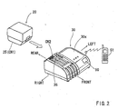
- FIG. 2 is a perspective view of a charger and a battery pack of the system;
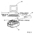
- FIG. 3 is a schematic perspective view showing the relation between the battery pack and a personal computer; and
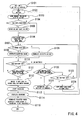
- FIG. 4 is a flowchart of showing the operation of the system;
- FIG. 5 is a schematic view of a lighting device;
- FIG. 6(A) is a diagram showing a circuit configuration of a battery charging system according to an alternative embodiment; and
- FIG. 6(B) is detailed circuit configuration of a sound generating circuit shown in FIG. 6(A).
- Each of the additional features and teachings disclosed above and below may be utilized separately or in conjunction with other features and teachings to provide improved charging systems. Representative examples of the present invention, which examples utilize many of these additional features and teachings both separately and in conjunction with one another, will now be described in detail with reference to the attached drawings. This detailed description is merely intended to teach a person of skill in the art further details for practicing preferred aspects of the present teachings and is not intended to limit the scope of the invention. Only the claims define the scope of the claimed invention. Therefore, combinations of features and steps disclosed in the following detailed description may not be necessary to practice the invention in the broadest sense, and are instead taught merely to particularly describe representative examples of the invention. Moreover, various features of the representative examples and the dependent claims may be combined in ways that are not specifically enumerated in order to provide additional useful embodiments of the present teachings.
- Embodiments according to the present invention will now be described with reference to FIGS. 1(A) and 1(B) to FIGS. 6(A) and 6(B).
- As shown in FIG(A), a
charging system 10 can generally include abattery pack 20 and acharger 30. Thebattery pack 20 is adapted to receive abattery 22 that can serve as a power source of a power tool (not shown). Thecharger 30 serves to charge thebattery 22. - As shown in FIG. 2, the
battery pack 20 can have a substantially prism-like configuration and include acoupler 25 disposed on the upper surface of thebattery pack 20. An electrical connector CN1 is provided at a suitable position of thecoupler 25 and is electrically connected to thebattery 22. The connector CN1 includes terminals connected to positive and negative electrodes of thebattery 22 and a communication terminal T that serves as a terminal of adata memory section 27 that will be explained later. - The
coupler 25 can be coupled to a corresponding coupler (not shown) provided on the power tool, so that thebattery pack 20 can be integrated with the power tool At the same that thecoupler 25 is coupled to the corresponding coupler, the positive and negative terminals of the connector CN1 of thebattery pack 20 are electrically connected to the corresponding terminals (not shown) of the power tool, so that the power of thebattery 22 can be supplied to a motor (not shown) of the power tool. - As shown in FIG. 1(A), a
data memory section 27 is disposed within thebattery pack 20. Thedata memory section 27 can store data of a variety of sound patters, such as melodies and buzzer sounds. Thememory section 27 permits the stored data to be rewritten. - Further, as shown in FIG. 3, the connector CN1 can be connected to a
data conversion adaptor 43 that can be further connected to apersonal computer 40 via a USB connector (not shown). Thedata conversion adapter 43 serves to connect thedata memory section 27 of thebattery pack 20 to thepersonal computer 40 in order to enable transmission of data stored in thepersonal computer 40 to thedata memory section 27. Therefore, it is possible to write the data stored in thepersonal computer 40 into thedata memory section 27 of thebattery pack 20. The date stored in thepersonal computer 40 can include melody data that has been downloaded into thecomputer 40 via the internet. - As shown in FIG. 2, the
charger 30 has a box-like housing 30x. Acoupler 35 is disposed on the right side portion of the upper surface of thehousing 30x and is adapted to be coupled to thebattery pack 20. An electrical connector CN2 is disposed at a suitable position of thecoupler 35 and can be electrically connected to thebattery pack 20 for charging thebattery 22. As shown in FIG. 1(A), similar to the connector CN1 of thebattery pack 20, the connector CN2 includes terminals for connecting to the corresponding terminals of the connector CN1 and a communication terminal T1 for connecting to the terminal T. - The
coupler 25 of thebattery pack 20 can be connected to thecoupler 35 of thecharger 30 by moving thebattery pack 20 from the rear side of thecharger 30. More specifically, thecoupler 25 can engage thecoupler 35 as thebattery pack 20 is slidably moved along the upper surface of thecharger 30 from the rear side of thecharger 30 as shown in FIG. 2. At the same time that thecoupler 25 is coupled to thecoupler 35, the connector CN1 of thebattery pack 20 can be electrically connected to the connector CN2 of thecharger 30. - As shown in FIG. 1(A), the
charger 30 has apower cord 30r that can be connected to an outlet of a household AC power source. Thepower cord 30r is electrically connected to inputterminals power source device 31 of thecharger 30. The DCpower source device 31 can convert the AC power into a first DC power (Vp volt power) used for a charging purpose and a second DC power (Vc volt power) used for a control purpose. - The first DC power is outputted from
first output terminals 31p and E of thepower source device 31 and is connected to positive and negative terminals of the connector CN2 via aswitch 36 that is controlled by aCPU 34. Here, the first output terminal E is an earth terminal. In this way, the connector CN2 of thecharger 30 is connected to the connector CN1 of thebattery pack 20, so that the first DC power (Vp power) is supplied to thebattery 22 of thebattery pack 20 in order to charge thebattery 22 when theswitch 36 is turned on. - The second DC power of the DC
power source device 31 is outputted fromsecond output terminals 31c and E to a controllerpower source device 33. The controllerpower source device 33 is used as a constant-voltage supply device for supplying the power to theCPU sound generating element 37, etc. - The charging operation of the
battery 22 can be controlled based on a program stored in amemory 34a of theCPU 34. Also, theCPU 34 is configured to check the charging operation of thebattery 22 using the voltage of thebattery 22, the temperature of thebattery 22, etc. When theCPU 34 determines that the charge to thebattery 22 has been completed, theCPU 34 turns off theswitch 36, so that the charging operation is terminated. - When the connector CN2 of the
charger 30 is connected to the connector CN1 of thebattery pack 20, theCPU 34 is connected to thedata memory section 27 of thebattery pack 20 via the communication terminals T and T1. TheCPU 34 also store a program for selecting data from the data of melody (or the like) stored in thedata memory section 27 of thebattery pack 20 and for selecting data from the data of melody (or the like) stored in theCPU 34. Based on the selected data of melody or the like, theCPU 34 actuates afirst driver 38a associated with thesound generating element 37 in order to generate the melody or the like by thesound generating element 37 when the operation for charging thebattery 22 has been completed. - The
sound generating element 37 may be a piezoelectric buzzer, a piezoelectric speaker or the like. As shown in FIGS. 1(A) and 1(B), thesound generating element 37 generates sounds by the actuation of thefirst driver 38a or asecond driver 38b. Each of the first andsecond drivers CPU 34. As shown in FIG. 1(B), a power source terminal of thefirst driver 38a is connected to the positive terminal of the connector CN2, so that a battery voltage Vp is applied to the power source terminal of thefirst driver 38a. A power source terminal of thesecond driver 38b is connected to the controllerpower source device 33, so that a voltage Vc is applied to the power source terminal of thesecond driver 38b. Here, the voltage Vc is set to be smaller than the voltage Vp. Therefore, when thefirst driver 38a is actuated, the voltage Vp is applied to thesound generating element 37, so that a large volume sound is produced. On the other hand, when thefirst driver 38b is actuated the voltage Vc is applied to thesound generating element 37, so that a small volume sound is produced. - Further, as shown in FIG. 5, an
LED 30e can be mounted to a circuit board to which the CPU is mounted. TheLED 30e is actuated by a signal that is outputted from theCPU 34 when the charging operation has been completed. TheLED 30e is covered by ahousing 30x of thecharger 30. Thehousing 30x has a transparent region, so that the light of theLED 30e can be emitted to the outside of thehousing 30x of thecharger 30 through the transparent region when the charging operation has been completed. - The operation of the charging
system 10 will now be described with reference to a flowchart shown in FIG. 4. The process of the flowchart is performed according to a program stored in thememory 34a of theCPU 34. - If the
coupler 25 of thebattery pack 20 is not coupled to thecouple 35 of thecharger 30, (i.e., if the connector CN2 of thecharger 30 is not electrically connected to the connector CN1 of the battery pack 20), theswitch 36 is held in an off position as shown in FIG. 1(A) (see Step S101). Thus, theswitch 36 is held in the off position unless thebattery 22 is set to thecharger 30 so as to be electrically connected to thecharger 30. The determination as to whether or not thebattery 22 is set can be made, for example, by monitoring the voltage at the positive terminal of the connector CN2 by theCPU 34. Thus, if the voltage value at the positive terminal of the connector CN2 is zero, theCPU 34 determines that the positive terminal of the connector CN2 is not electrically connected to thebattery 22, and therefore, thebattery 22 is not set. Alternatively, it is possible to determine that thebattery 22 is not set if a sensor or other suitable detector detects that theCPU 34 is not connected to thedata memory section 27 of thebattery pack 20. - If the
battery 20 has been set to thecharger 30 in Step S102, the process then proceeds to Step S103 in which theCPU 34 sends a request for melody data to thedata memory section 27 of thebattery pack 20. Then, the process proceeds to Step S104 in which theCPU 34 determines whether or not the melody data is stored in thedata memory section 27. If the determination in Step S104 is "YES", the process proceeds to Step S105 in which the stored melody data is copied to adata memory section 34c of theCPU 34. Then, the process proceeds to Step S106 in which a first sound code of the melody data or other sound data is copied from thedata memory section 34a of theCPU 34 to awork area 34c of theCPU 34. The process further proceeds to Step S107 in which theCPU 34 determines if the copied first sound code designates a buzzer sound. If the determination is "YES", the process proceeds to Step S108 in which theCPU 34 outputs a buzzer sound signal to thesecond driver 38b, so that thesound generating element 37 generates a buzzer or beeping sound. This buzzer or beeping sound is small because the voltage Vc is applied to thesecond driver 38b. - If the first sound code copied to the
work area 34c does not designate a buzzer or beeping sound but designates a melody, determination "NO" is resulted in Step S107. Then, the process proceeds to Step S109 in which theCPU 34 outputs a melody signal corresponding to the copied first sound code to thesecond driver 38b, so that thesound generating element 37 generates a melody sound designated by the first sound code. - From Step S108 and S109, the process proceeds to Step S110 in which the
CPU 34 determines if thebattery 22 is set to thecharger 30. If the operator wishes to change the buzzer (or beeping) sound or the melody sound to a different melody sound, the operator can disconnect the connector CN1 of thebattery pack 20 from the connector CN2 of thecharger 30 within three seconds after generation of the buzzer (or beeping) sound or the melody sound. Then, determination "NO" is resulted in Step S110 and the process proceeds to Step S120 in which theCPU 34 determines if the disconnected state has continued more than three seconds. If the operator reconnects the connector CN1 to the connector CN2 within three seconds after the connector CN1 has been disconnected from the connector CN2, determination "NO" is resulted in Step S120 and the process proceeds to Step S123. Because the determination in Step S123 is "YES", the process further proceeds to Step S124 where a next sound code of the stored data is copied to thework area 34c. Thereafter, the process returns to Step S107 in which theCPU 34 determines if the copied sound code designates a buzzer sound. As described previously, if the determination is "YES", the process proceeds to Step S108 in which theCPU 34 outputs a buzzer sound signal to thesecond driver 38b, so that thesound generating element 37 generates a buzzer or beeping sound. If the determination in Step S107 is "NO", the process proceeds to StepS 109 in which thesound generating element 37 receives a melody signal and generates a melody sound designated by the copied second sound code. - If the operator wishes to again change the melody sound, the operator can again disconnect the connector CN1 from the connector CN2 and thereafter reconnects the connector CN1 to the connector CN2 in order to repeat the process of Steps S110-S120-S123-S124 and Steps S107-S108-S109-S110.
- If the connector CN1 has been disconnected from the connector CN2 more than three seconds, determination "YES" results in Step S120. Then, the
CPU 34 determines that thebattery 22 is removed in Step S121 and the process returns to Step S101 in order to wait until thebattery 22 is set. - Further, if the operator does not wish to change the melody sound generated in Step S109, the operator is not required to take any action. Thus, the process proceeds to Step S111 in which the
CPU 34 determines if three seconds has passed after the melody sound has been generated. If the determination in Step S111 is "YES", the step proceeds to Step S112 in which the sound code of the lastly generated melody sound is written as a first sound code. Then, the generation of the melody sound is stopped - In this way, the sound to be generated is selected by the process of Steps S110-S120-S123-S124 and Steps S107-S108-S109-S110 performed by the program stored in the
CPU 34. TheCPU 34 of thecharger 30 serves to store various sound patterns or types, from which the sound to be generated is selected. - After completion of selection of the sound to be generated, the
CPU 34 sends a signal to theswitch 36 in order to turn on theswitch 36. Then, the voltage of the first DC power from the DCpower source device 31 is applied to thebattery 22 of thebattery pack 20. Thus, the charging of thebattery 22 is started in Step S113. When the charging operation has been completed, the CPU sends a signal to turn off theswitch 36 in Step S114. The process then proceeds to Step S115 in which the CPU sends a signal corresponding to the selected sound to thefirst driver 38a, so that thesound generating element 37 generates the selected sound in Step S115. Because thefirst driver 38a applies the voltage Vp supplied from thebattery 22, thesound generating element 37 generates a large sound. Simultaneously with the generation of the sound, theCPU 34 can send a signal to theLED 30e, so that theLED 30e emits the light. - Therefore, in this embodiment, the DC
power source device 31 supplying the first DC power, the CPU, and theswitch 36, serve as a charge control device. Thefirst driver 38a and thesound generating element 37 serve as a sound generation device for generating the sound when the charging operation has been completed. TheCPU 34 and theLED 30e serve as a lighting device. - With the charging
system 10 according to the embodiment, by virtue of the sound selecting function of theCPU 34, it is possible to select a desired sound from various sounds that are different in pattern or type and include various melody sounds and/or a buzzer (or beeping) sound. Therefore, even in the event that several charging systems are used at the same work cite, the selection of the sound enables the operator to easily reliably recognize the completion of the charging operation by a particular charging system. In addition, by selecting different sounds for different charging systems, it is possible to easily recognize which charging system has completed the charging operation. - In addition, by repeatedly performing the operation of disconnecting the connector CN1 on the battery side from the connector CN2 on the charger side and subsequently reconnecting the connector CN1 to the connector CN2 before the charging operation is started, it is possible to sequentially select the sound from several sounds that are stored in the
data memory section 27 of thebattery pack 20 in addition to the sounds previously stored in thedata memory section 34b of theCPU 34. Therefore, it is not necessary to provide an additional switch for selecting the sound. As a result, the manufacturing cost can be reduced. - Further, during the selection of the sound, the
sound generating element 27 generates the selected sound at a volume smaller than the volume of the selected sound that will be produced when the charging operation has been completed. This enables the operator to select the sound while he or she listens to the sound that is being selected. Therefore, the selection of the sound can be efficiently and reliably performed. - Furthermore, the sound data can be written into the
data memory section 27 of thebattery pack 20 from thepersonal computer 40. Therefore, for example, if the operator downloads his or her favorite melody, music or any other sounds into thecomputer 40, the operator can select such a sound for generation by thesound generating element 27. Therefore, the operator can more clearly distinguish his or her charging system from other charging systems. - Still furthermore, the completion of the charging operation of the
battery 22 can be easily visually recognized because theLED 30e emits light when the charging operation has been completed. - The present invention may not be limited to the above embodiment. Thus, the above embodiment may be modified in various ways without departing from the spirit of the invention. For example, the following modification can be made:
- In the above embodiment, the
first driver 38a and thesecond driver 38b shown in FIG. 1(A) were used in order to change the voltage applied to thesound generating element 37 between the state where the sound is being selected and the state where the charging operation has been completed. Alternatively, it is possible to use the configuration shown in FIGS. 6(A) and 6(B). In the configuration shown in FIGS. 6(A) and 6(B), the voltage Vp from thebattery 22 is supplied to afirst rectifier 39a. A voltage Vh from another power source (not shown) is higher than the control voltage Vc and is supplied to asecond rectifier 39b. The output side of each of thefirst rectifier 39a and thesecond rectifier 39b is connected to thesound generating element 37. In addition, adriver 38 is connected in series between thesound generating element 37 and the earth. With this arrangement, it is possible that one of the voltage Vp or the voltage Vh having a higher value than the other is applied to thesound generating element 37, so that it is possible to generate a sound as large as possible during the selection of the sound and when the charging operation has been completed. - In the above embodiment, the light can be emitted from the
LED 30e simultaneously with generation of the sound when the charging operation has been completed. However, in place of or in addition to theLED 30e, it is possible to provide atransmitter 50 for transmitting a charge completion signal that can be received by acellular phone 51 or other remote receiver (see FIG. 2). Therefore, the operator can recognize the completion of the charging operation even if he or she is away from the work cite. - In the above embodiment, the sound is- selected by performing the operation of disconnecting the connector CN1 on the battery side from the connector CN2 on the charger side and subsequently reconnecting the connector CN1 to the connector CN2. However, a switch can be incorporated in order to select the sound.
It is explicitly stated that all features disclosed in the description and/or the claims are intended to be disclosed separately and independently from each other for the purpose of original disclosure as well as for the purpose of restricting the claimed invention independent of the composition of the features in the embodiments and/or the claims. It is explicitly stated that all value ranges or indications of groups of entities disclose every possible intermediate value or intermediate entity for the purpose of original disclosure as well as for the purpose of restricting the claimed invention, in particular as limits of value ranges.
Claims (15)
- A system for charging a power tool battery (22), comprising:a battery side connector (CN1) and a charger side connector (CN2) electrically connectable to each other;a charging device (31, 34, 36) capable of charging the battery (22) when the battery side connector (CN1) and the charger side connector (CN2) are electrically connected;a memory device (34b) capable of storing data of a plurality of sound patterns;a selecting device (34) capable of selecting a sound pattern data from the data of the plurality of sound patterns stored in the memory device (34b);a sound generating device (38a, 37) capable of generating a sound based on the selected sound pattern data when the charging operation of the battery (22) by the charging device (31, 34, 36) has been completed.
- The system as in claim 1, wherein:the charging device (31, 34, 36) starts the charging operation when a predetermined time has passed after the battery side connector (CN1) and the charger side connector (CN2) has been connected.
- The system as in claim 2, wherein the selecting device (34) changes the selected sound pattern data with the next sound pattern data stored in the memory device (34b) when the battery side connector (CN1) and the charger side connector (CN2) have been disconnected and reconnected to each other.
- The system as in any one of the preceding claims, wherein:the sound generating device (38a, 37) is also capable of generating the sound based on the selected sound pattern data during the selecting operation by the selecting device (34).
- The system as in claim 4, wherein a volume of the sound generated during the selecting operation is smaller than a volume of the sound generated when the charging operation of the battery (22) by the charging device (31, 34, 36) has been completed.
- The system as in any one of the preceding claims, wherein:the sound generating device (38a, 37) comprises a sound generating element (37) that can generate a sound when a voltage is applied.
- The system as in claim 6, wherein a volume of the sound generated by the sound generating element (37) can be varied in response to a change of the voltage.
- The system as in any one of the preceding claims, wherein;the sound pattern memory device (34b) is configured such that sound pattern data from a personal computer (40) can be written into the sound pattern memory device (34b).
- The system as in any one of the preceding claims, further comprising a lighting device (34, 30e) including a light emitter (30e) that can emit light when the battery charging operation by the charging device (31, 34, 36) has been completed.
- The system as in any one of the preceding claims, further comprising a transmitter (50) that can transmit a signal receivable by a communication terminal device (51) when the charging operation by the charging device (31, 34, 36) has been completed.
- A system for charging a battery (22) comprising:a battery charger (30) capable of charging the battery (22) and comprising:a first memory (34b) capable of storing sound data groups;a sound generating device (38a, 37) capable of generating a sound;a controller (34) capable of selecting one of the sound data groups and instructing the sound generating device (38a, 37) to generate the sound based on the selected sound data group when a charging operation of the battery (22) has been completed.
- The system as in claim 11, wherein the controller (34) is capable of instructing the sound generating device (38a, 37) to generate the sound based on the selected sound data group when the sound data group has been selected.
- The system as in claim 11 or 12, further comprising a battery pack (20) constructed to receive the battery (22), so that the battery (22) is electrically connectable to the battery (22) charger via the battery pack (20),
wherein the battery pack (20) includes a second memory (27) capable of storing the sound data groups, and
wherein the controller (34) is capable of copying the sound data stored within the second memory (27) to the first memory (34b). - The system as in any one of claims 11 to 13, wherein the controller (34) is capable of selecting the sound data in response to the operation of electrically disconnecting and reconnecting between the battery charger (30) and the battery (22).
- A system for charging a battery (22) comprising:a charging device (31, 34, 36) capable of charging a battery (22);a memory device (34b) capable of storing data of a plurality of sound patterns;a selecting device (34) capable of selecting a sound pattern data from the plurality of sound patterns;a sound generating device (38a, 37) capable of generating a sound based on the selected sound pattern data when the charging operation of the battery (22) by the charging device (31, 34, 36) has been completed.
Applications Claiming Priority (1)
| Application Number | Priority Date | Filing Date | Title |
|---|---|---|---|
| JP2006121964A JP4566943B2 (en) | 2006-04-26 | 2006-04-26 | Charger |
Publications (3)
| Publication Number | Publication Date |
|---|---|
| EP1850444A2 true EP1850444A2 (en) | 2007-10-31 |
| EP1850444A3 EP1850444A3 (en) | 2008-11-12 |
| EP1850444B1 EP1850444B1 (en) | 2012-08-01 |
Family
ID=38235147
Family Applications (1)
| Application Number | Title | Priority Date | Filing Date |
|---|---|---|---|
| EP07008439A Active EP1850444B1 (en) | 2006-04-26 | 2007-04-25 | Battery charging systems |
Country Status (4)
| Country | Link |
|---|---|
| US (1) | US7944175B2 (en) |
| EP (1) | EP1850444B1 (en) |
| JP (1) | JP4566943B2 (en) |
| CN (1) | CN101064439B (en) |
Cited By (1)
| Publication number | Priority date | Publication date | Assignee | Title |
|---|---|---|---|---|
| US9813110B2 (en) | 2013-05-14 | 2017-11-07 | Robert Bosch Gmbh | Data transmission using an electrical machine |
Families Citing this family (511)
| Publication number | Priority date | Publication date | Assignee | Title |
|---|---|---|---|---|
| US20070084897A1 (en) | 2003-05-20 | 2007-04-19 | Shelton Frederick E Iv | Articulating surgical stapling instrument incorporating a two-piece e-beam firing mechanism |
| US9060770B2 (en) | 2003-05-20 | 2015-06-23 | Ethicon Endo-Surgery, Inc. | Robotically-driven surgical instrument with E-beam driver |
| US9072535B2 (en) | 2011-05-27 | 2015-07-07 | Ethicon Endo-Surgery, Inc. | Surgical stapling instruments with rotatable staple deployment arrangements |
| US8215531B2 (en) | 2004-07-28 | 2012-07-10 | Ethicon Endo-Surgery, Inc. | Surgical stapling instrument having a medical substance dispenser |
| US11890012B2 (en) | 2004-07-28 | 2024-02-06 | Cilag Gmbh International | Staple cartridge comprising cartridge body and attached support |
| US11998198B2 (en) | 2004-07-28 | 2024-06-04 | Cilag Gmbh International | Surgical stapling instrument incorporating a two-piece E-beam firing mechanism |
| US7673781B2 (en) | 2005-08-31 | 2010-03-09 | Ethicon Endo-Surgery, Inc. | Surgical stapling device with staple driver that supports multiple wire diameter staples |
| US7934630B2 (en) | 2005-08-31 | 2011-05-03 | Ethicon Endo-Surgery, Inc. | Staple cartridges for forming staples having differing formed staple heights |
| US10159482B2 (en) | 2005-08-31 | 2018-12-25 | Ethicon Llc | Fastener cartridge assembly comprising a fixed anvil and different staple heights |
| US11484312B2 (en) | 2005-08-31 | 2022-11-01 | Cilag Gmbh International | Staple cartridge comprising a staple driver arrangement |
| US11246590B2 (en) | 2005-08-31 | 2022-02-15 | Cilag Gmbh International | Staple cartridge including staple drivers having different unfired heights |
| US8800838B2 (en) | 2005-08-31 | 2014-08-12 | Ethicon Endo-Surgery, Inc. | Robotically-controlled cable-based surgical end effectors |
| US7669746B2 (en) | 2005-08-31 | 2010-03-02 | Ethicon Endo-Surgery, Inc. | Staple cartridges for forming staples having differing formed staple heights |
| US9237891B2 (en) | 2005-08-31 | 2016-01-19 | Ethicon Endo-Surgery, Inc. | Robotically-controlled surgical stapling devices that produce formed staples having different lengths |
| US20070106317A1 (en) | 2005-11-09 | 2007-05-10 | Shelton Frederick E Iv | Hydraulically and electrically actuated articulation joints for surgical instruments |
| US8763879B2 (en) | 2006-01-31 | 2014-07-01 | Ethicon Endo-Surgery, Inc. | Accessing data stored in a memory of surgical instrument |
| US11278279B2 (en) | 2006-01-31 | 2022-03-22 | Cilag Gmbh International | Surgical instrument assembly |
| US8708213B2 (en) | 2006-01-31 | 2014-04-29 | Ethicon Endo-Surgery, Inc. | Surgical instrument having a feedback system |
| US20120292367A1 (en) | 2006-01-31 | 2012-11-22 | Ethicon Endo-Surgery, Inc. | Robotically-controlled end effector |
| US8186555B2 (en) | 2006-01-31 | 2012-05-29 | Ethicon Endo-Surgery, Inc. | Motor-driven surgical cutting and fastening instrument with mechanical closure system |
| US8161977B2 (en) | 2006-01-31 | 2012-04-24 | Ethicon Endo-Surgery, Inc. | Accessing data stored in a memory of a surgical instrument |
| US7753904B2 (en) | 2006-01-31 | 2010-07-13 | Ethicon Endo-Surgery, Inc. | Endoscopic surgical instrument with a handle that can articulate with respect to the shaft |
| US9861359B2 (en) | 2006-01-31 | 2018-01-09 | Ethicon Llc | Powered surgical instruments with firing system lockout arrangements |
| US7845537B2 (en) | 2006-01-31 | 2010-12-07 | Ethicon Endo-Surgery, Inc. | Surgical instrument having recording capabilities |
| US8820603B2 (en) | 2006-01-31 | 2014-09-02 | Ethicon Endo-Surgery, Inc. | Accessing data stored in a memory of a surgical instrument |
| US20110006101A1 (en) | 2009-02-06 | 2011-01-13 | EthiconEndo-Surgery, Inc. | Motor driven surgical fastener device with cutting member lockout arrangements |
| US20110024477A1 (en) | 2009-02-06 | 2011-02-03 | Hall Steven G | Driven Surgical Stapler Improvements |
| US20110290856A1 (en) | 2006-01-31 | 2011-12-01 | Ethicon Endo-Surgery, Inc. | Robotically-controlled surgical instrument with force-feedback capabilities |
| US11224427B2 (en) | 2006-01-31 | 2022-01-18 | Cilag Gmbh International | Surgical stapling system including a console and retraction assembly |
| US11793518B2 (en) | 2006-01-31 | 2023-10-24 | Cilag Gmbh International | Powered surgical instruments with firing system lockout arrangements |
| US8992422B2 (en) | 2006-03-23 | 2015-03-31 | Ethicon Endo-Surgery, Inc. | Robotically-controlled endoscopic accessory channel |
| US20070225562A1 (en) | 2006-03-23 | 2007-09-27 | Ethicon Endo-Surgery, Inc. | Articulating endoscopic accessory channel |
| US8322455B2 (en) | 2006-06-27 | 2012-12-04 | Ethicon Endo-Surgery, Inc. | Manually driven surgical cutting and fastening instrument |
| US10130359B2 (en) | 2006-09-29 | 2018-11-20 | Ethicon Llc | Method for forming a staple |
| US8485412B2 (en) | 2006-09-29 | 2013-07-16 | Ethicon Endo-Surgery, Inc. | Surgical staples having attached drivers and stapling instruments for deploying the same |
| US10568652B2 (en) | 2006-09-29 | 2020-02-25 | Ethicon Llc | Surgical staples having attached drivers of different heights and stapling instruments for deploying the same |
| US11980366B2 (en) | 2006-10-03 | 2024-05-14 | Cilag Gmbh International | Surgical instrument |
| US8459520B2 (en) | 2007-01-10 | 2013-06-11 | Ethicon Endo-Surgery, Inc. | Surgical instrument with wireless communication between control unit and remote sensor |
| US8652120B2 (en) | 2007-01-10 | 2014-02-18 | Ethicon Endo-Surgery, Inc. | Surgical instrument with wireless communication between control unit and sensor transponders |
| US8632535B2 (en) | 2007-01-10 | 2014-01-21 | Ethicon Endo-Surgery, Inc. | Interlock and surgical instrument including same |
| US8684253B2 (en) | 2007-01-10 | 2014-04-01 | Ethicon Endo-Surgery, Inc. | Surgical instrument with wireless communication between a control unit of a robotic system and remote sensor |
| US11291441B2 (en) | 2007-01-10 | 2022-04-05 | Cilag Gmbh International | Surgical instrument with wireless communication between control unit and remote sensor |
| US20080169332A1 (en) | 2007-01-11 | 2008-07-17 | Shelton Frederick E | Surgical stapling device with a curved cutting member |
| US11039836B2 (en) | 2007-01-11 | 2021-06-22 | Cilag Gmbh International | Staple cartridge for use with a surgical stapling instrument |
| US8727197B2 (en) | 2007-03-15 | 2014-05-20 | Ethicon Endo-Surgery, Inc. | Staple cartridge cavity configuration with cooperative surgical staple |
| US8893946B2 (en) | 2007-03-28 | 2014-11-25 | Ethicon Endo-Surgery, Inc. | Laparoscopic tissue thickness and clamp load measuring devices |
| US8931682B2 (en) | 2007-06-04 | 2015-01-13 | Ethicon Endo-Surgery, Inc. | Robotically-controlled shaft based rotary drive systems for surgical instruments |
| US8534528B2 (en) | 2007-06-04 | 2013-09-17 | Ethicon Endo-Surgery, Inc. | Surgical instrument having a multiple rate directional switching mechanism |
| US11857181B2 (en) | 2007-06-04 | 2024-01-02 | Cilag Gmbh International | Robotically-controlled shaft based rotary drive systems for surgical instruments |
| US8308040B2 (en) | 2007-06-22 | 2012-11-13 | Ethicon Endo-Surgery, Inc. | Surgical stapling instrument with an articulatable end effector |
| US7753245B2 (en) | 2007-06-22 | 2010-07-13 | Ethicon Endo-Surgery, Inc. | Surgical stapling instruments |
| US11849941B2 (en) | 2007-06-29 | 2023-12-26 | Cilag Gmbh International | Staple cartridge having staple cavities extending at a transverse angle relative to a longitudinal cartridge axis |
| KR101474421B1 (en) * | 2007-11-23 | 2014-12-19 | 엘지전자 주식회사 | Mobile terminal having charging menu setting function and mutual charging method using the same |
| US8561870B2 (en) | 2008-02-13 | 2013-10-22 | Ethicon Endo-Surgery, Inc. | Surgical stapling instrument |
| US7819298B2 (en) | 2008-02-14 | 2010-10-26 | Ethicon Endo-Surgery, Inc. | Surgical stapling apparatus with control features operable with one hand |
| US8459525B2 (en) | 2008-02-14 | 2013-06-11 | Ethicon Endo-Sugery, Inc. | Motorized surgical cutting and fastening instrument having a magnetic drive train torque limiting device |
| US8622274B2 (en) | 2008-02-14 | 2014-01-07 | Ethicon Endo-Surgery, Inc. | Motorized cutting and fastening instrument having control circuit for optimizing battery usage |
| US8573465B2 (en) | 2008-02-14 | 2013-11-05 | Ethicon Endo-Surgery, Inc. | Robotically-controlled surgical end effector system with rotary actuated closure systems |
| US7866527B2 (en) | 2008-02-14 | 2011-01-11 | Ethicon Endo-Surgery, Inc. | Surgical stapling apparatus with interlockable firing system |
| US8657174B2 (en) | 2008-02-14 | 2014-02-25 | Ethicon Endo-Surgery, Inc. | Motorized surgical cutting and fastening instrument having handle based power source |
| US8636736B2 (en) | 2008-02-14 | 2014-01-28 | Ethicon Endo-Surgery, Inc. | Motorized surgical cutting and fastening instrument |
| US11986183B2 (en) | 2008-02-14 | 2024-05-21 | Cilag Gmbh International | Surgical cutting and fastening instrument comprising a plurality of sensors to measure an electrical parameter |
| US8752749B2 (en) | 2008-02-14 | 2014-06-17 | Ethicon Endo-Surgery, Inc. | Robotically-controlled disposable motor-driven loading unit |
| US8584919B2 (en) | 2008-02-14 | 2013-11-19 | Ethicon Endo-Sugery, Inc. | Surgical stapling apparatus with load-sensitive firing mechanism |
| US9179912B2 (en) * | 2008-02-14 | 2015-11-10 | Ethicon Endo-Surgery, Inc. | Robotically-controlled motorized surgical cutting and fastening instrument |
| RU2493788C2 (en) | 2008-02-14 | 2013-09-27 | Этикон Эндо-Серджери, Инк. | Surgical cutting and fixing instrument, which has radio-frequency electrodes |
| US7793812B2 (en) | 2008-02-14 | 2010-09-14 | Ethicon Endo-Surgery, Inc. | Disposable motor-driven loading unit for use with a surgical cutting and stapling apparatus |
| US8758391B2 (en) | 2008-02-14 | 2014-06-24 | Ethicon Endo-Surgery, Inc. | Interchangeable tools for surgical instruments |
| US11272927B2 (en) | 2008-02-15 | 2022-03-15 | Cilag Gmbh International | Layer arrangements for surgical staple cartridges |
| US20130153641A1 (en) | 2008-02-15 | 2013-06-20 | Ethicon Endo-Surgery, Inc. | Releasable layer of material and surgical end effector having the same |
| PL3476312T3 (en) | 2008-09-19 | 2024-03-11 | Ethicon Llc | Surgical stapler with apparatus for adjusting staple height |
| US7954686B2 (en) | 2008-09-19 | 2011-06-07 | Ethicon Endo-Surgery, Inc. | Surgical stapler with apparatus for adjusting staple height |
| US9005230B2 (en) | 2008-09-23 | 2015-04-14 | Ethicon Endo-Surgery, Inc. | Motorized surgical instrument |
| US11648005B2 (en) | 2008-09-23 | 2023-05-16 | Cilag Gmbh International | Robotically-controlled motorized surgical instrument with an end effector |
| US9050083B2 (en) | 2008-09-23 | 2015-06-09 | Ethicon Endo-Surgery, Inc. | Motorized surgical instrument |
| US8210411B2 (en) | 2008-09-23 | 2012-07-03 | Ethicon Endo-Surgery, Inc. | Motor-driven surgical cutting instrument |
| US9386983B2 (en) | 2008-09-23 | 2016-07-12 | Ethicon Endo-Surgery, Llc | Robotically-controlled motorized surgical instrument |
| US8608045B2 (en) | 2008-10-10 | 2013-12-17 | Ethicon Endo-Sugery, Inc. | Powered surgical cutting and stapling apparatus with manually retractable firing system |
| US8517239B2 (en) | 2009-02-05 | 2013-08-27 | Ethicon Endo-Surgery, Inc. | Surgical stapling instrument comprising a magnetic element driver |
| US8444036B2 (en) | 2009-02-06 | 2013-05-21 | Ethicon Endo-Surgery, Inc. | Motor driven surgical fastener device with mechanisms for adjusting a tissue gap within the end effector |
| JP2012517287A (en) | 2009-02-06 | 2012-08-02 | エシコン・エンド−サージェリィ・インコーポレイテッド | Improvement of driven surgical stapler |
| JP5432652B2 (en) * | 2009-09-25 | 2014-03-05 | パナソニック株式会社 | Battery charger for electric tools |
| US8220688B2 (en) | 2009-12-24 | 2012-07-17 | Ethicon Endo-Surgery, Inc. | Motor-driven surgical cutting instrument with electric actuator directional control assembly |
| US8851354B2 (en) | 2009-12-24 | 2014-10-07 | Ethicon Endo-Surgery, Inc. | Surgical cutting instrument that analyzes tissue thickness |
| JP5461221B2 (en) | 2010-02-12 | 2014-04-02 | 株式会社マキタ | Electric tool powered by multiple battery packs |
| JP5432761B2 (en) | 2010-02-12 | 2014-03-05 | 株式会社マキタ | Electric tool powered by multiple battery packs |
| US8783543B2 (en) | 2010-07-30 | 2014-07-22 | Ethicon Endo-Surgery, Inc. | Tissue acquisition arrangements and methods for surgical stapling devices |
| US9877720B2 (en) | 2010-09-24 | 2018-01-30 | Ethicon Llc | Control features for articulating surgical device |
| US11925354B2 (en) | 2010-09-30 | 2024-03-12 | Cilag Gmbh International | Staple cartridge comprising staples positioned within a compressible portion thereof |
| US10405854B2 (en) | 2010-09-30 | 2019-09-10 | Ethicon Llc | Surgical stapling cartridge with layer retention features |
| US9307989B2 (en) | 2012-03-28 | 2016-04-12 | Ethicon Endo-Surgery, Llc | Tissue stapler having a thickness compensator incorportating a hydrophobic agent |
| US9232941B2 (en) | 2010-09-30 | 2016-01-12 | Ethicon Endo-Surgery, Inc. | Tissue thickness compensator comprising a reservoir |
| US9320523B2 (en) | 2012-03-28 | 2016-04-26 | Ethicon Endo-Surgery, Llc | Tissue thickness compensator comprising tissue ingrowth features |
| US9364233B2 (en) | 2010-09-30 | 2016-06-14 | Ethicon Endo-Surgery, Llc | Tissue thickness compensators for circular surgical staplers |
| US9220501B2 (en) | 2010-09-30 | 2015-12-29 | Ethicon Endo-Surgery, Inc. | Tissue thickness compensators |
| US10945731B2 (en) | 2010-09-30 | 2021-03-16 | Ethicon Llc | Tissue thickness compensator comprising controlled release and expansion |
| US11298125B2 (en) | 2010-09-30 | 2022-04-12 | Cilag Gmbh International | Tissue stapler having a thickness compensator |
| US12213666B2 (en) | 2010-09-30 | 2025-02-04 | Cilag Gmbh International | Tissue thickness compensator comprising layers |
| US9301752B2 (en) | 2010-09-30 | 2016-04-05 | Ethicon Endo-Surgery, Llc | Tissue thickness compensator comprising a plurality of capsules |
| US9629814B2 (en) | 2010-09-30 | 2017-04-25 | Ethicon Endo-Surgery, Llc | Tissue thickness compensator configured to redistribute compressive forces |
| US9055941B2 (en) | 2011-09-23 | 2015-06-16 | Ethicon Endo-Surgery, Inc. | Staple cartridge including collapsible deck |
| AU2011308701B2 (en) | 2010-09-30 | 2013-11-14 | Ethicon Endo-Surgery, Inc. | Fastener system comprising a retention matrix and an alignment matrix |
| US9241714B2 (en) | 2011-04-29 | 2016-01-26 | Ethicon Endo-Surgery, Inc. | Tissue thickness compensator and method for making the same |
| US9314246B2 (en) | 2010-09-30 | 2016-04-19 | Ethicon Endo-Surgery, Llc | Tissue stapler having a thickness compensator incorporating an anti-inflammatory agent |
| US9332974B2 (en) | 2010-09-30 | 2016-05-10 | Ethicon Endo-Surgery, Llc | Layered tissue thickness compensator |
| US9220500B2 (en) | 2010-09-30 | 2015-12-29 | Ethicon Endo-Surgery, Inc. | Tissue thickness compensator comprising structure to produce a resilient load |
| US9301753B2 (en) | 2010-09-30 | 2016-04-05 | Ethicon Endo-Surgery, Llc | Expandable tissue thickness compensator |
| US8893949B2 (en) | 2010-09-30 | 2014-11-25 | Ethicon Endo-Surgery, Inc. | Surgical stapler with floating anvil |
| US11812965B2 (en) | 2010-09-30 | 2023-11-14 | Cilag Gmbh International | Layer of material for a surgical end effector |
| US9113865B2 (en) | 2010-09-30 | 2015-08-25 | Ethicon Endo-Surgery, Inc. | Staple cartridge comprising a layer |
| US8695866B2 (en) | 2010-10-01 | 2014-04-15 | Ethicon Endo-Surgery, Inc. | Surgical instrument having a power control circuit |
| BR112013027794B1 (en) | 2011-04-29 | 2020-12-15 | Ethicon Endo-Surgery, Inc | CLAMP CARTRIDGE SET |
| US11207064B2 (en) | 2011-05-27 | 2021-12-28 | Cilag Gmbh International | Automated end effector component reloading system for use with a robotic system |
| US8692509B2 (en) * | 2011-06-23 | 2014-04-08 | Black & Decker Inc. | Charge control scheme for use in power tools |
| CN108270271A (en) * | 2011-06-30 | 2018-07-10 | 松下知识产权经营株式会社 | Supply unit |
| EP2735077B1 (en) | 2011-07-24 | 2017-06-21 | Makita Corporation | Portable battery pack charging system and method for recharging a battery pack |
| US9050084B2 (en) | 2011-09-23 | 2015-06-09 | Ethicon Endo-Surgery, Inc. | Staple cartridge including collapsible deck arrangement |
| US9044230B2 (en) | 2012-02-13 | 2015-06-02 | Ethicon Endo-Surgery, Inc. | Surgical cutting and fastening instrument with apparatus for determining cartridge and firing motion status |
| MX350846B (en) | 2012-03-28 | 2017-09-22 | Ethicon Endo Surgery Inc | Tissue thickness compensator comprising capsules defining a low pressure environment. |
| US9198662B2 (en) | 2012-03-28 | 2015-12-01 | Ethicon Endo-Surgery, Inc. | Tissue thickness compensator having improved visibility |
| MX358135B (en) | 2012-03-28 | 2018-08-06 | Ethicon Endo Surgery Inc | Tissue thickness compensator comprising a plurality of layers. |
| CN104379068B (en) | 2012-03-28 | 2017-09-22 | 伊西康内外科公司 | Holding device assembly including tissue thickness compensation part |
| US9101358B2 (en) | 2012-06-15 | 2015-08-11 | Ethicon Endo-Surgery, Inc. | Articulatable surgical instrument comprising a firing drive |
| US9561038B2 (en) | 2012-06-28 | 2017-02-07 | Ethicon Endo-Surgery, Llc | Interchangeable clip applier |
| US9119657B2 (en) | 2012-06-28 | 2015-09-01 | Ethicon Endo-Surgery, Inc. | Rotary actuatable closure arrangement for surgical end effector |
| US9282974B2 (en) | 2012-06-28 | 2016-03-15 | Ethicon Endo-Surgery, Llc | Empty clip cartridge lockout |
| US12383267B2 (en) | 2012-06-28 | 2025-08-12 | Cilag Gmbh International | Robotically powered surgical device with manually-actuatable reversing system |
| US20140001231A1 (en) | 2012-06-28 | 2014-01-02 | Ethicon Endo-Surgery, Inc. | Firing system lockout arrangements for surgical instruments |
| JP6290201B2 (en) | 2012-06-28 | 2018-03-07 | エシコン・エンド−サージェリィ・インコーポレイテッドEthicon Endo−Surgery,Inc. | Lockout for empty clip cartridge |
| US9028494B2 (en) | 2012-06-28 | 2015-05-12 | Ethicon Endo-Surgery, Inc. | Interchangeable end effector coupling arrangement |
| US9125662B2 (en) | 2012-06-28 | 2015-09-08 | Ethicon Endo-Surgery, Inc. | Multi-axis articulating and rotating surgical tools |
| BR112014032776B1 (en) | 2012-06-28 | 2021-09-08 | Ethicon Endo-Surgery, Inc | SURGICAL INSTRUMENT SYSTEM AND SURGICAL KIT FOR USE WITH A SURGICAL INSTRUMENT SYSTEM |
| US11197671B2 (en) | 2012-06-28 | 2021-12-14 | Cilag Gmbh International | Stapling assembly comprising a lockout |
| US9289256B2 (en) | 2012-06-28 | 2016-03-22 | Ethicon Endo-Surgery, Llc | Surgical end effectors having angled tissue-contacting surfaces |
| US9226751B2 (en) | 2012-06-28 | 2016-01-05 | Ethicon Endo-Surgery, Inc. | Surgical instrument system including replaceable end effectors |
| US9101385B2 (en) | 2012-06-28 | 2015-08-11 | Ethicon Endo-Surgery, Inc. | Electrode connections for rotary driven surgical tools |
| US9072536B2 (en) | 2012-06-28 | 2015-07-07 | Ethicon Endo-Surgery, Inc. | Differential locking arrangements for rotary powered surgical instruments |
| US8747238B2 (en) | 2012-06-28 | 2014-06-10 | Ethicon Endo-Surgery, Inc. | Rotary drive shaft assemblies for surgical instruments with articulatable end effectors |
| US9204879B2 (en) | 2012-06-28 | 2015-12-08 | Ethicon Endo-Surgery, Inc. | Flexible drive member |
| US9386984B2 (en) | 2013-02-08 | 2016-07-12 | Ethicon Endo-Surgery, Llc | Staple cartridge comprising a releasable cover |
| US10092292B2 (en) | 2013-02-28 | 2018-10-09 | Ethicon Llc | Staple forming features for surgical stapling instrument |
| US9307986B2 (en) | 2013-03-01 | 2016-04-12 | Ethicon Endo-Surgery, Llc | Surgical instrument soft stop |
| MX368026B (en) | 2013-03-01 | 2019-09-12 | Ethicon Endo Surgery Inc | Articulatable surgical instruments with conductive pathways for signal communication. |
| RU2669463C2 (en) | 2013-03-01 | 2018-10-11 | Этикон Эндо-Серджери, Инк. | Surgical instrument with soft stop |
| US9345481B2 (en) | 2013-03-13 | 2016-05-24 | Ethicon Endo-Surgery, Llc | Staple cartridge tissue thickness sensor system |
| US9351726B2 (en) | 2013-03-14 | 2016-05-31 | Ethicon Endo-Surgery, Llc | Articulation control system for articulatable surgical instruments |
| US9629629B2 (en) | 2013-03-14 | 2017-04-25 | Ethicon Endo-Surgey, LLC | Control systems for surgical instruments |
| US9572577B2 (en) | 2013-03-27 | 2017-02-21 | Ethicon Endo-Surgery, Llc | Fastener cartridge comprising a tissue thickness compensator including openings therein |
| US9795384B2 (en) | 2013-03-27 | 2017-10-24 | Ethicon Llc | Fastener cartridge comprising a tissue thickness compensator and a gap setting element |
| US9332984B2 (en) | 2013-03-27 | 2016-05-10 | Ethicon Endo-Surgery, Llc | Fastener cartridge assemblies |
| BR112015026109B1 (en) | 2013-04-16 | 2022-02-22 | Ethicon Endo-Surgery, Inc | surgical instrument |
| US9801626B2 (en) | 2013-04-16 | 2017-10-31 | Ethicon Llc | Modular motor driven surgical instruments with alignment features for aligning rotary drive shafts with surgical end effector shafts |
| US9574644B2 (en) | 2013-05-30 | 2017-02-21 | Ethicon Endo-Surgery, Llc | Power module for use with a surgical instrument |
| MX369362B (en) | 2013-08-23 | 2019-11-06 | Ethicon Endo Surgery Llc | Firing member retraction devices for powered surgical instruments. |
| US20150053737A1 (en) | 2013-08-23 | 2015-02-26 | Ethicon Endo-Surgery, Inc. | End effector detection systems for surgical instruments |
| US9724092B2 (en) | 2013-12-23 | 2017-08-08 | Ethicon Llc | Modular surgical instruments |
| US20150173756A1 (en) | 2013-12-23 | 2015-06-25 | Ethicon Endo-Surgery, Inc. | Surgical cutting and stapling methods |
| US9839428B2 (en) | 2013-12-23 | 2017-12-12 | Ethicon Llc | Surgical cutting and stapling instruments with independent jaw control features |
| US9687232B2 (en) | 2013-12-23 | 2017-06-27 | Ethicon Llc | Surgical staples |
| US9962161B2 (en) | 2014-02-12 | 2018-05-08 | Ethicon Llc | Deliverable surgical instrument |
| BR112016019387B1 (en) | 2014-02-24 | 2022-11-29 | Ethicon Endo-Surgery, Llc | SURGICAL INSTRUMENT SYSTEM AND FASTENER CARTRIDGE FOR USE WITH A SURGICAL FIXING INSTRUMENT |
| US9757124B2 (en) | 2014-02-24 | 2017-09-12 | Ethicon Llc | Implantable layer assemblies |
| US20150272557A1 (en) | 2014-03-26 | 2015-10-01 | Ethicon Endo-Surgery, Inc. | Modular surgical instrument system |
| US9913642B2 (en) | 2014-03-26 | 2018-03-13 | Ethicon Llc | Surgical instrument comprising a sensor system |
| US9750499B2 (en) | 2014-03-26 | 2017-09-05 | Ethicon Llc | Surgical stapling instrument system |
| US10013049B2 (en) | 2014-03-26 | 2018-07-03 | Ethicon Llc | Power management through sleep options of segmented circuit and wake up control |
| BR112016021943B1 (en) | 2014-03-26 | 2022-06-14 | Ethicon Endo-Surgery, Llc | SURGICAL INSTRUMENT FOR USE BY AN OPERATOR IN A SURGICAL PROCEDURE |
| US12232723B2 (en) | 2014-03-26 | 2025-02-25 | Cilag Gmbh International | Systems and methods for controlling a segmented circuit |
| JP6532889B2 (en) | 2014-04-16 | 2019-06-19 | エシコン エルエルシーEthicon LLC | Fastener cartridge assembly and staple holder cover arrangement |
| US20150297223A1 (en) | 2014-04-16 | 2015-10-22 | Ethicon Endo-Surgery, Inc. | Fastener cartridges including extensions having different configurations |
| US10561422B2 (en) | 2014-04-16 | 2020-02-18 | Ethicon Llc | Fastener cartridge comprising deployable tissue engaging members |
| CN106456158B (en) | 2014-04-16 | 2019-02-05 | 伊西康内外科有限责任公司 | Fastener magazines including non-conforming fasteners |
| CN106456176B (en) | 2014-04-16 | 2019-06-28 | 伊西康内外科有限责任公司 | Fastener Cartridge Including Extensions With Different Configurations |
| US10327764B2 (en) | 2014-09-26 | 2019-06-25 | Ethicon Llc | Method for creating a flexible staple line |
| US10045781B2 (en) | 2014-06-13 | 2018-08-14 | Ethicon Llc | Closure lockout systems for surgical instruments |
| JP6300271B2 (en) * | 2014-07-22 | 2018-03-28 | 株式会社マキタ | Chainsaw |
| US11311294B2 (en) | 2014-09-05 | 2022-04-26 | Cilag Gmbh International | Powered medical device including measurement of closure state of jaws |
| BR112017004361B1 (en) | 2014-09-05 | 2023-04-11 | Ethicon Llc | ELECTRONIC SYSTEM FOR A SURGICAL INSTRUMENT |
| US9724094B2 (en) | 2014-09-05 | 2017-08-08 | Ethicon Llc | Adjunct with integrated sensors to quantify tissue compression |
| US10105142B2 (en) | 2014-09-18 | 2018-10-23 | Ethicon Llc | Surgical stapler with plurality of cutting elements |
| US11523821B2 (en) | 2014-09-26 | 2022-12-13 | Cilag Gmbh International | Method for creating a flexible staple line |
| JP6648119B2 (en) | 2014-09-26 | 2020-02-14 | エシコン エルエルシーEthicon LLC | Surgical stapling buttress and accessory materials |
| US10076325B2 (en) | 2014-10-13 | 2018-09-18 | Ethicon Llc | Surgical stapling apparatus comprising a tissue stop |
| US9924944B2 (en) | 2014-10-16 | 2018-03-27 | Ethicon Llc | Staple cartridge comprising an adjunct material |
| US11141153B2 (en) | 2014-10-29 | 2021-10-12 | Cilag Gmbh International | Staple cartridges comprising driver arrangements |
| US10517594B2 (en) | 2014-10-29 | 2019-12-31 | Ethicon Llc | Cartridge assemblies for surgical staplers |
| US9844376B2 (en) | 2014-11-06 | 2017-12-19 | Ethicon Llc | Staple cartridge comprising a releasable adjunct material |
| US10736636B2 (en) | 2014-12-10 | 2020-08-11 | Ethicon Llc | Articulatable surgical instrument system |
| US10117649B2 (en) | 2014-12-18 | 2018-11-06 | Ethicon Llc | Surgical instrument assembly comprising a lockable articulation system |
| US9987000B2 (en) | 2014-12-18 | 2018-06-05 | Ethicon Llc | Surgical instrument assembly comprising a flexible articulation system |
| US9844374B2 (en) | 2014-12-18 | 2017-12-19 | Ethicon Llc | Surgical instrument systems comprising an articulatable end effector and means for adjusting the firing stroke of a firing member |
| US10085748B2 (en) | 2014-12-18 | 2018-10-02 | Ethicon Llc | Locking arrangements for detachable shaft assemblies with articulatable surgical end effectors |
| US9844375B2 (en) | 2014-12-18 | 2017-12-19 | Ethicon Llc | Drive arrangements for articulatable surgical instruments |
| US10245027B2 (en) | 2014-12-18 | 2019-04-02 | Ethicon Llc | Surgical instrument with an anvil that is selectively movable about a discrete non-movable axis relative to a staple cartridge |
| US10188385B2 (en) | 2014-12-18 | 2019-01-29 | Ethicon Llc | Surgical instrument system comprising lockable systems |
| RU2703684C2 (en) | 2014-12-18 | 2019-10-21 | ЭТИКОН ЭНДО-СЕРДЖЕРИ, ЭлЭлСи | Surgical instrument with anvil which is selectively movable relative to staple cartridge around discrete fixed axis |
| US10159483B2 (en) | 2015-02-27 | 2018-12-25 | Ethicon Llc | Surgical apparatus configured to track an end-of-life parameter |
| US11154301B2 (en) | 2015-02-27 | 2021-10-26 | Cilag Gmbh International | Modular stapling assembly |
| US10226250B2 (en) | 2015-02-27 | 2019-03-12 | Ethicon Llc | Modular stapling assembly |
| US10180463B2 (en) | 2015-02-27 | 2019-01-15 | Ethicon Llc | Surgical apparatus configured to assess whether a performance parameter of the surgical apparatus is within an acceptable performance band |
| JP2020121162A (en) | 2015-03-06 | 2020-08-13 | エシコン エルエルシーEthicon LLC | Time dependent evaluation of sensor data to determine stability element, creep element and viscoelastic element of measurement |
| US9924961B2 (en) | 2015-03-06 | 2018-03-27 | Ethicon Endo-Surgery, Llc | Interactive feedback system for powered surgical instruments |
| US9901342B2 (en) | 2015-03-06 | 2018-02-27 | Ethicon Endo-Surgery, Llc | Signal and power communication system positioned on a rotatable shaft |
| US9808246B2 (en) | 2015-03-06 | 2017-11-07 | Ethicon Endo-Surgery, Llc | Method of operating a powered surgical instrument |
| US10548504B2 (en) | 2015-03-06 | 2020-02-04 | Ethicon Llc | Overlaid multi sensor radio frequency (RF) electrode system to measure tissue compression |
| US10245033B2 (en) | 2015-03-06 | 2019-04-02 | Ethicon Llc | Surgical instrument comprising a lockable battery housing |
| US10687806B2 (en) | 2015-03-06 | 2020-06-23 | Ethicon Llc | Adaptive tissue compression techniques to adjust closure rates for multiple tissue types |
| US10617412B2 (en) | 2015-03-06 | 2020-04-14 | Ethicon Llc | System for detecting the mis-insertion of a staple cartridge into a surgical stapler |
| US9993248B2 (en) | 2015-03-06 | 2018-06-12 | Ethicon Endo-Surgery, Llc | Smart sensors with local signal processing |
| US10045776B2 (en) | 2015-03-06 | 2018-08-14 | Ethicon Llc | Control techniques and sub-processor contained within modular shaft with select control processing from handle |
| US10441279B2 (en) | 2015-03-06 | 2019-10-15 | Ethicon Llc | Multiple level thresholds to modify operation of powered surgical instruments |
| US9895148B2 (en) | 2015-03-06 | 2018-02-20 | Ethicon Endo-Surgery, Llc | Monitoring speed control and precision incrementing of motor for powered surgical instruments |
| US10390825B2 (en) | 2015-03-31 | 2019-08-27 | Ethicon Llc | Surgical instrument with progressive rotary drive systems |
| US10335149B2 (en) | 2015-06-18 | 2019-07-02 | Ethicon Llc | Articulatable surgical instruments with composite firing beam structures with center firing support member for articulation support |
| US11058425B2 (en) | 2015-08-17 | 2021-07-13 | Ethicon Llc | Implantable layers for a surgical instrument |
| US11103248B2 (en) | 2015-08-26 | 2021-08-31 | Cilag Gmbh International | Surgical staples for minimizing staple roll |
| MX2022009705A (en) | 2015-08-26 | 2022-11-07 | Ethicon Llc | Surgical staples comprising hardness variations for improved fastening of tissue. |
| MX2018002388A (en) | 2015-08-26 | 2018-08-01 | Ethicon Llc | Surgical staple strips for permitting varying staple properties and enabling easy cartridge loading. |
| JP6858754B2 (en) | 2015-08-26 | 2021-04-14 | エシコン エルエルシーEthicon LLC | Staple cartridge assembly with various tissue compression gaps and staple molding gaps |
| MX2022006189A (en) | 2015-09-02 | 2022-06-16 | Ethicon Llc | Surgical staple configurations with camming surfaces located between portions supporting surgical staples. |
| US10251648B2 (en) | 2015-09-02 | 2019-04-09 | Ethicon Llc | Surgical staple cartridge staple drivers with central support features |
| US10238386B2 (en) | 2015-09-23 | 2019-03-26 | Ethicon Llc | Surgical stapler having motor control based on an electrical parameter related to a motor current |
| US10076326B2 (en) | 2015-09-23 | 2018-09-18 | Ethicon Llc | Surgical stapler having current mirror-based motor control |
| US10105139B2 (en) | 2015-09-23 | 2018-10-23 | Ethicon Llc | Surgical stapler having downstream current-based motor control |
| US10363036B2 (en) | 2015-09-23 | 2019-07-30 | Ethicon Llc | Surgical stapler having force-based motor control |
| US10085751B2 (en) | 2015-09-23 | 2018-10-02 | Ethicon Llc | Surgical stapler having temperature-based motor control |
| US10327769B2 (en) | 2015-09-23 | 2019-06-25 | Ethicon Llc | Surgical stapler having motor control based on a drive system component |
| US10299878B2 (en) | 2015-09-25 | 2019-05-28 | Ethicon Llc | Implantable adjunct systems for determining adjunct skew |
| US10736633B2 (en) | 2015-09-30 | 2020-08-11 | Ethicon Llc | Compressible adjunct with looping members |
| US11890015B2 (en) | 2015-09-30 | 2024-02-06 | Cilag Gmbh International | Compressible adjunct with crossing spacer fibers |
| US10172620B2 (en) | 2015-09-30 | 2019-01-08 | Ethicon Llc | Compressible adjuncts with bonding nodes |
| US10980539B2 (en) | 2015-09-30 | 2021-04-20 | Ethicon Llc | Implantable adjunct comprising bonded layers |
| US10368865B2 (en) | 2015-12-30 | 2019-08-06 | Ethicon Llc | Mechanisms for compensating for drivetrain failure in powered surgical instruments |
| US10292704B2 (en) | 2015-12-30 | 2019-05-21 | Ethicon Llc | Mechanisms for compensating for battery pack failure in powered surgical instruments |
| US10265068B2 (en) | 2015-12-30 | 2019-04-23 | Ethicon Llc | Surgical instruments with separable motors and motor control circuits |
| US11213293B2 (en) | 2016-02-09 | 2022-01-04 | Cilag Gmbh International | Articulatable surgical instruments with single articulation link arrangements |
| US10413291B2 (en) | 2016-02-09 | 2019-09-17 | Ethicon Llc | Surgical instrument articulation mechanism with slotted secondary constraint |
| BR112018016098B1 (en) | 2016-02-09 | 2023-02-23 | Ethicon Llc | SURGICAL INSTRUMENT |
| US10258331B2 (en) | 2016-02-12 | 2019-04-16 | Ethicon Llc | Mechanisms for compensating for drivetrain failure in powered surgical instruments |
| US10448948B2 (en) | 2016-02-12 | 2019-10-22 | Ethicon Llc | Mechanisms for compensating for drivetrain failure in powered surgical instruments |
| US11224426B2 (en) | 2016-02-12 | 2022-01-18 | Cilag Gmbh International | Mechanisms for compensating for drivetrain failure in powered surgical instruments |
| US10617413B2 (en) | 2016-04-01 | 2020-04-14 | Ethicon Llc | Closure system arrangements for surgical cutting and stapling devices with separate and distinct firing shafts |
| US11064997B2 (en) | 2016-04-01 | 2021-07-20 | Cilag Gmbh International | Surgical stapling instrument |
| US11179150B2 (en) | 2016-04-15 | 2021-11-23 | Cilag Gmbh International | Systems and methods for controlling a surgical stapling and cutting instrument |
| US11607239B2 (en) | 2016-04-15 | 2023-03-21 | Cilag Gmbh International | Systems and methods for controlling a surgical stapling and cutting instrument |
| US10492783B2 (en) | 2016-04-15 | 2019-12-03 | Ethicon, Llc | Surgical instrument with improved stop/start control during a firing motion |
| US10335145B2 (en) | 2016-04-15 | 2019-07-02 | Ethicon Llc | Modular surgical instrument with configurable operating mode |
| US10426467B2 (en) | 2016-04-15 | 2019-10-01 | Ethicon Llc | Surgical instrument with detection sensors |
| US10456137B2 (en) | 2016-04-15 | 2019-10-29 | Ethicon Llc | Staple formation detection mechanisms |
| US10405859B2 (en) | 2016-04-15 | 2019-09-10 | Ethicon Llc | Surgical instrument with adjustable stop/start control during a firing motion |
| US10828028B2 (en) | 2016-04-15 | 2020-11-10 | Ethicon Llc | Surgical instrument with multiple program responses during a firing motion |
| US10357247B2 (en) | 2016-04-15 | 2019-07-23 | Ethicon Llc | Surgical instrument with multiple program responses during a firing motion |
| US11317917B2 (en) | 2016-04-18 | 2022-05-03 | Cilag Gmbh International | Surgical stapling system comprising a lockable firing assembly |
| US20170296173A1 (en) | 2016-04-18 | 2017-10-19 | Ethicon Endo-Surgery, Llc | Method for operating a surgical instrument |
| US10433840B2 (en) | 2016-04-18 | 2019-10-08 | Ethicon Llc | Surgical instrument comprising a replaceable cartridge jaw |
| US10675024B2 (en) | 2016-06-24 | 2020-06-09 | Ethicon Llc | Staple cartridge comprising overdriven staples |
| USD847989S1 (en) | 2016-06-24 | 2019-05-07 | Ethicon Llc | Surgical fastener cartridge |
| JP6957532B2 (en) | 2016-06-24 | 2021-11-02 | エシコン エルエルシーEthicon LLC | Staple cartridges including wire staples and punched staples |
| BR112018076831B1 (en) | 2016-06-24 | 2023-01-31 | Ethicon Llc | SURGICAL STAPPING SYSTEM |
| USD850617S1 (en) | 2016-06-24 | 2019-06-04 | Ethicon Llc | Surgical fastener cartridge |
| USD826405S1 (en) | 2016-06-24 | 2018-08-21 | Ethicon Llc | Surgical fastener |
| US10500000B2 (en) | 2016-08-16 | 2019-12-10 | Ethicon Llc | Surgical tool with manual control of end effector jaws |
| US10617414B2 (en) | 2016-12-21 | 2020-04-14 | Ethicon Llc | Closure member arrangements for surgical instruments |
| US20180168615A1 (en) | 2016-12-21 | 2018-06-21 | Ethicon Endo-Surgery, Llc | Method of deforming staples from two different types of staple cartridges with the same surgical stapling instrument |
| US10667811B2 (en) | 2016-12-21 | 2020-06-02 | Ethicon Llc | Surgical stapling instruments and staple-forming anvils |
| US11419606B2 (en) | 2016-12-21 | 2022-08-23 | Cilag Gmbh International | Shaft assembly comprising a clutch configured to adapt the output of a rotary firing member to two different systems |
| US10568626B2 (en) | 2016-12-21 | 2020-02-25 | Ethicon Llc | Surgical instruments with jaw opening features for increasing a jaw opening distance |
| CN110099619B (en) | 2016-12-21 | 2022-07-15 | 爱惜康有限责任公司 | Latching device for surgical end effector and replaceable tool assembly |
| JP7010956B2 (en) | 2016-12-21 | 2022-01-26 | エシコン エルエルシー | How to staple tissue |
| US11134942B2 (en) | 2016-12-21 | 2021-10-05 | Cilag Gmbh International | Surgical stapling instruments and staple-forming anvils |
| US10758230B2 (en) | 2016-12-21 | 2020-09-01 | Ethicon Llc | Surgical instrument with primary and safety processors |
| US10687810B2 (en) | 2016-12-21 | 2020-06-23 | Ethicon Llc | Stepped staple cartridge with tissue retention and gap setting features |
| JP2020501815A (en) | 2016-12-21 | 2020-01-23 | エシコン エルエルシーEthicon LLC | Surgical stapling system |
| US10639035B2 (en) | 2016-12-21 | 2020-05-05 | Ethicon Llc | Surgical stapling instruments and replaceable tool assemblies thereof |
| US10499914B2 (en) | 2016-12-21 | 2019-12-10 | Ethicon Llc | Staple forming pocket arrangements |
| US10918385B2 (en) | 2016-12-21 | 2021-02-16 | Ethicon Llc | Surgical system comprising a firing member rotatable into an articulation state to articulate an end effector of the surgical system |
| US10779823B2 (en) | 2016-12-21 | 2020-09-22 | Ethicon Llc | Firing member pin angle |
| US11090048B2 (en) | 2016-12-21 | 2021-08-17 | Cilag Gmbh International | Method for resetting a fuse of a surgical instrument shaft |
| US10993715B2 (en) | 2016-12-21 | 2021-05-04 | Ethicon Llc | Staple cartridge comprising staples with different clamping breadths |
| JP7010957B2 (en) | 2016-12-21 | 2022-01-26 | エシコン エルエルシー | Shaft assembly with lockout |
| US10881401B2 (en) | 2016-12-21 | 2021-01-05 | Ethicon Llc | Staple firing member comprising a missing cartridge and/or spent cartridge lockout |
| US20180168623A1 (en) | 2016-12-21 | 2018-06-21 | Ethicon Endo-Surgery, Llc | Surgical stapling systems |
| US10537324B2 (en) | 2016-12-21 | 2020-01-21 | Ethicon Llc | Stepped staple cartridge with asymmetrical staples |
| US20180168609A1 (en) | 2016-12-21 | 2018-06-21 | Ethicon Endo-Surgery, Llc | Firing assembly comprising a fuse |
| US10945727B2 (en) | 2016-12-21 | 2021-03-16 | Ethicon Llc | Staple cartridge with deformable driver retention features |
| CN110114014B (en) | 2016-12-21 | 2022-08-09 | 爱惜康有限责任公司 | Surgical instrument system including end effector and firing assembly lockout |
| MX2019007311A (en) | 2016-12-21 | 2019-11-18 | Ethicon Llc | Surgical stapling systems. |
| US10426471B2 (en) | 2016-12-21 | 2019-10-01 | Ethicon Llc | Surgical instrument with multiple failure response modes |
| US11684367B2 (en) | 2016-12-21 | 2023-06-27 | Cilag Gmbh International | Stepped assembly having and end-of-life indicator |
| USD879808S1 (en) | 2017-06-20 | 2020-03-31 | Ethicon Llc | Display panel with graphical user interface |
| US11090046B2 (en) | 2017-06-20 | 2021-08-17 | Cilag Gmbh International | Systems and methods for controlling displacement member motion of a surgical stapling and cutting instrument |
| US10813639B2 (en) | 2017-06-20 | 2020-10-27 | Ethicon Llc | Closed loop feedback control of motor velocity of a surgical stapling and cutting instrument based on system conditions |
| US12490980B2 (en) | 2017-06-20 | 2025-12-09 | Cilag Gmbh International | Surgical instrument having controllable articulation velocity |
| US10390841B2 (en) | 2017-06-20 | 2019-08-27 | Ethicon Llc | Control of motor velocity of a surgical stapling and cutting instrument based on angle of articulation |
| US11517325B2 (en) | 2017-06-20 | 2022-12-06 | Cilag Gmbh International | Closed loop feedback control of motor velocity of a surgical stapling and cutting instrument based on measured displacement distance traveled over a specified time interval |
| USD879809S1 (en) | 2017-06-20 | 2020-03-31 | Ethicon Llc | Display panel with changeable graphical user interface |
| US10646220B2 (en) | 2017-06-20 | 2020-05-12 | Ethicon Llc | Systems and methods for controlling displacement member velocity for a surgical instrument |
| US10881399B2 (en) | 2017-06-20 | 2021-01-05 | Ethicon Llc | Techniques for adaptive control of motor velocity of a surgical stapling and cutting instrument |
| US10779820B2 (en) | 2017-06-20 | 2020-09-22 | Ethicon Llc | Systems and methods for controlling motor speed according to user input for a surgical instrument |
| US10307170B2 (en) | 2017-06-20 | 2019-06-04 | Ethicon Llc | Method for closed loop control of motor velocity of a surgical stapling and cutting instrument |
| USD890784S1 (en) | 2017-06-20 | 2020-07-21 | Ethicon Llc | Display panel with changeable graphical user interface |
| US11071554B2 (en) | 2017-06-20 | 2021-07-27 | Cilag Gmbh International | Closed loop feedback control of motor velocity of a surgical stapling and cutting instrument based on magnitude of velocity error measurements |
| US10368864B2 (en) | 2017-06-20 | 2019-08-06 | Ethicon Llc | Systems and methods for controlling displaying motor velocity for a surgical instrument |
| US10888321B2 (en) | 2017-06-20 | 2021-01-12 | Ethicon Llc | Systems and methods for controlling velocity of a displacement member of a surgical stapling and cutting instrument |
| US10624633B2 (en) | 2017-06-20 | 2020-04-21 | Ethicon Llc | Systems and methods for controlling motor velocity of a surgical stapling and cutting instrument |
| US10881396B2 (en) | 2017-06-20 | 2021-01-05 | Ethicon Llc | Surgical instrument with variable duration trigger arrangement |
| US10327767B2 (en) | 2017-06-20 | 2019-06-25 | Ethicon Llc | Control of motor velocity of a surgical stapling and cutting instrument based on angle of articulation |
| US10980537B2 (en) | 2017-06-20 | 2021-04-20 | Ethicon Llc | Closed loop feedback control of motor velocity of a surgical stapling and cutting instrument based on measured time over a specified number of shaft rotations |
| US11653914B2 (en) | 2017-06-20 | 2023-05-23 | Cilag Gmbh International | Systems and methods for controlling motor velocity of a surgical stapling and cutting instrument according to articulation angle of end effector |
| US11382638B2 (en) | 2017-06-20 | 2022-07-12 | Cilag Gmbh International | Closed loop feedback control of motor velocity of a surgical stapling and cutting instrument based on measured time over a specified displacement distance |
| US11090049B2 (en) | 2017-06-27 | 2021-08-17 | Cilag Gmbh International | Staple forming pocket arrangements |
| US10993716B2 (en) | 2017-06-27 | 2021-05-04 | Ethicon Llc | Surgical anvil arrangements |
| US10772629B2 (en) | 2017-06-27 | 2020-09-15 | Ethicon Llc | Surgical anvil arrangements |
| US11324503B2 (en) | 2017-06-27 | 2022-05-10 | Cilag Gmbh International | Surgical firing member arrangements |
| US11266405B2 (en) | 2017-06-27 | 2022-03-08 | Cilag Gmbh International | Surgical anvil manufacturing methods |
| US10856869B2 (en) | 2017-06-27 | 2020-12-08 | Ethicon Llc | Surgical anvil arrangements |
| USD906355S1 (en) | 2017-06-28 | 2020-12-29 | Ethicon Llc | Display screen or portion thereof with a graphical user interface for a surgical instrument |
| US20190000461A1 (en) | 2017-06-28 | 2019-01-03 | Ethicon Llc | Surgical cutting and fastening devices with pivotable anvil with a tissue locating arrangement in close proximity to an anvil pivot axis |
| US11246592B2 (en) | 2017-06-28 | 2022-02-15 | Cilag Gmbh International | Surgical instrument comprising an articulation system lockable to a frame |
| USD851762S1 (en) | 2017-06-28 | 2019-06-18 | Ethicon Llc | Anvil |
| US11259805B2 (en) | 2017-06-28 | 2022-03-01 | Cilag Gmbh International | Surgical instrument comprising firing member supports |
| BR112019027065B1 (en) | 2017-06-28 | 2023-12-26 | Ethicon Llc | SURGICAL INSTRUMENT AND SURGICAL SYSTEM |
| US10211586B2 (en) | 2017-06-28 | 2019-02-19 | Ethicon Llc | Surgical shaft assemblies with watertight housings |
| US11000279B2 (en) | 2017-06-28 | 2021-05-11 | Ethicon Llc | Surgical instrument comprising an articulation system ratio |
| US10765427B2 (en) | 2017-06-28 | 2020-09-08 | Ethicon Llc | Method for articulating a surgical instrument |
| US10903685B2 (en) | 2017-06-28 | 2021-01-26 | Ethicon Llc | Surgical shaft assemblies with slip ring assemblies forming capacitive channels |
| US10716614B2 (en) | 2017-06-28 | 2020-07-21 | Ethicon Llc | Surgical shaft assemblies with slip ring assemblies with increased contact pressure |
| USD869655S1 (en) | 2017-06-28 | 2019-12-10 | Ethicon Llc | Surgical fastener cartridge |
| US11564686B2 (en) | 2017-06-28 | 2023-01-31 | Cilag Gmbh International | Surgical shaft assemblies with flexible interfaces |
| USD854151S1 (en) | 2017-06-28 | 2019-07-16 | Ethicon Llc | Surgical instrument shaft |
| EP4070740B1 (en) | 2017-06-28 | 2025-03-26 | Cilag GmbH International | Surgical instrument comprising selectively actuatable rotatable couplers |
| US10932772B2 (en) | 2017-06-29 | 2021-03-02 | Ethicon Llc | Methods for closed loop velocity control for robotic surgical instrument |
| US10258418B2 (en) | 2017-06-29 | 2019-04-16 | Ethicon Llc | System for controlling articulation forces |
| US10398434B2 (en) | 2017-06-29 | 2019-09-03 | Ethicon Llc | Closed loop velocity control of closure member for robotic surgical instrument |
| US11007022B2 (en) | 2017-06-29 | 2021-05-18 | Ethicon Llc | Closed loop velocity control techniques based on sensed tissue parameters for robotic surgical instrument |
| US10898183B2 (en) | 2017-06-29 | 2021-01-26 | Ethicon Llc | Robotic surgical instrument with closed loop feedback techniques for advancement of closure member during firing |
| US11944300B2 (en) | 2017-08-03 | 2024-04-02 | Cilag Gmbh International | Method for operating a surgical system bailout |
| US11471155B2 (en) | 2017-08-03 | 2022-10-18 | Cilag Gmbh International | Surgical system bailout |
| US11304695B2 (en) | 2017-08-03 | 2022-04-19 | Cilag Gmbh International | Surgical system shaft interconnection |
| US11974742B2 (en) | 2017-08-03 | 2024-05-07 | Cilag Gmbh International | Surgical system comprising an articulation bailout |
| US10765429B2 (en) | 2017-09-29 | 2020-09-08 | Ethicon Llc | Systems and methods for providing alerts according to the operational state of a surgical instrument |
| USD907647S1 (en) | 2017-09-29 | 2021-01-12 | Ethicon Llc | Display screen or portion thereof with animated graphical user interface |
| USD907648S1 (en) | 2017-09-29 | 2021-01-12 | Ethicon Llc | Display screen or portion thereof with animated graphical user interface |
| US10743872B2 (en) | 2017-09-29 | 2020-08-18 | Ethicon Llc | System and methods for controlling a display of a surgical instrument |
| USD917500S1 (en) | 2017-09-29 | 2021-04-27 | Ethicon Llc | Display screen or portion thereof with graphical user interface |
| US10729501B2 (en) | 2017-09-29 | 2020-08-04 | Ethicon Llc | Systems and methods for language selection of a surgical instrument |
| US11399829B2 (en) | 2017-09-29 | 2022-08-02 | Cilag Gmbh International | Systems and methods of initiating a power shutdown mode for a surgical instrument |
| US10796471B2 (en) | 2017-09-29 | 2020-10-06 | Ethicon Llc | Systems and methods of displaying a knife position for a surgical instrument |
| US11134944B2 (en) | 2017-10-30 | 2021-10-05 | Cilag Gmbh International | Surgical stapler knife motion controls |
| US11090075B2 (en) | 2017-10-30 | 2021-08-17 | Cilag Gmbh International | Articulation features for surgical end effector |
| US10779903B2 (en) | 2017-10-31 | 2020-09-22 | Ethicon Llc | Positive shaft rotation lock activated by jaw closure |
| US10842490B2 (en) | 2017-10-31 | 2020-11-24 | Ethicon Llc | Cartridge body design with force reduction based on firing completion |
| US10869666B2 (en) | 2017-12-15 | 2020-12-22 | Ethicon Llc | Adapters with control systems for controlling multiple motors of an electromechanical surgical instrument |
| US10779826B2 (en) | 2017-12-15 | 2020-09-22 | Ethicon Llc | Methods of operating surgical end effectors |
| US10779825B2 (en) | 2017-12-15 | 2020-09-22 | Ethicon Llc | Adapters with end effector position sensing and control arrangements for use in connection with electromechanical surgical instruments |
| US10828033B2 (en) | 2017-12-15 | 2020-11-10 | Ethicon Llc | Handheld electromechanical surgical instruments with improved motor control arrangements for positioning components of an adapter coupled thereto |
| US10966718B2 (en) | 2017-12-15 | 2021-04-06 | Ethicon Llc | Dynamic clamping assemblies with improved wear characteristics for use in connection with electromechanical surgical instruments |
| US11071543B2 (en) | 2017-12-15 | 2021-07-27 | Cilag Gmbh International | Surgical end effectors with clamping assemblies configured to increase jaw aperture ranges |
| US11197670B2 (en) | 2017-12-15 | 2021-12-14 | Cilag Gmbh International | Surgical end effectors with pivotal jaws configured to touch at their respective distal ends when fully closed |
| US10687813B2 (en) | 2017-12-15 | 2020-06-23 | Ethicon Llc | Adapters with firing stroke sensing arrangements for use in connection with electromechanical surgical instruments |
| US11033267B2 (en) | 2017-12-15 | 2021-06-15 | Ethicon Llc | Systems and methods of controlling a clamping member firing rate of a surgical instrument |
| US10743875B2 (en) | 2017-12-15 | 2020-08-18 | Ethicon Llc | Surgical end effectors with jaw stiffener arrangements configured to permit monitoring of firing member |
| US11006955B2 (en) | 2017-12-15 | 2021-05-18 | Ethicon Llc | End effectors with positive jaw opening features for use with adapters for electromechanical surgical instruments |
| US10743874B2 (en) | 2017-12-15 | 2020-08-18 | Ethicon Llc | Sealed adapters for use with electromechanical surgical instruments |
| US11020112B2 (en) | 2017-12-19 | 2021-06-01 | Ethicon Llc | Surgical tools configured for interchangeable use with different controller interfaces |
| US10729509B2 (en) | 2017-12-19 | 2020-08-04 | Ethicon Llc | Surgical instrument comprising closure and firing locking mechanism |
| US10716565B2 (en) | 2017-12-19 | 2020-07-21 | Ethicon Llc | Surgical instruments with dual articulation drivers |
| US10835330B2 (en) | 2017-12-19 | 2020-11-17 | Ethicon Llc | Method for determining the position of a rotatable jaw of a surgical instrument attachment assembly |
| USD910847S1 (en) | 2017-12-19 | 2021-02-16 | Ethicon Llc | Surgical instrument assembly |
| US11045270B2 (en) | 2017-12-19 | 2021-06-29 | Cilag Gmbh International | Robotic attachment comprising exterior drive actuator |
| US12336705B2 (en) | 2017-12-21 | 2025-06-24 | Cilag Gmbh International | Continuous use self-propelled stapling instrument |
| US11751867B2 (en) | 2017-12-21 | 2023-09-12 | Cilag Gmbh International | Surgical instrument comprising sequenced systems |
| US11311290B2 (en) | 2017-12-21 | 2022-04-26 | Cilag Gmbh International | Surgical instrument comprising an end effector dampener |
| US11129680B2 (en) | 2017-12-21 | 2021-09-28 | Cilag Gmbh International | Surgical instrument comprising a projector |
| US11076853B2 (en) | 2017-12-21 | 2021-08-03 | Cilag Gmbh International | Systems and methods of displaying a knife position during transection for a surgical instrument |
| US10912559B2 (en) | 2018-08-20 | 2021-02-09 | Ethicon Llc | Reinforced deformable anvil tip for surgical stapler anvil |
| US20200054321A1 (en) | 2018-08-20 | 2020-02-20 | Ethicon Llc | Surgical instruments with progressive jaw closure arrangements |
| US10842492B2 (en) | 2018-08-20 | 2020-11-24 | Ethicon Llc | Powered articulatable surgical instruments with clutching and locking arrangements for linking an articulation drive system to a firing drive system |
| US11291440B2 (en) | 2018-08-20 | 2022-04-05 | Cilag Gmbh International | Method for operating a powered articulatable surgical instrument |
| US11324501B2 (en) | 2018-08-20 | 2022-05-10 | Cilag Gmbh International | Surgical stapling devices with improved closure members |
| US10856870B2 (en) | 2018-08-20 | 2020-12-08 | Ethicon Llc | Switching arrangements for motor powered articulatable surgical instruments |
| US11039834B2 (en) | 2018-08-20 | 2021-06-22 | Cilag Gmbh International | Surgical stapler anvils with staple directing protrusions and tissue stability features |
| US11207065B2 (en) | 2018-08-20 | 2021-12-28 | Cilag Gmbh International | Method for fabricating surgical stapler anvils |
| US11045192B2 (en) | 2018-08-20 | 2021-06-29 | Cilag Gmbh International | Fabricating techniques for surgical stapler anvils |
| US10779821B2 (en) | 2018-08-20 | 2020-09-22 | Ethicon Llc | Surgical stapler anvils with tissue stop features configured to avoid tissue pinch |
| US11083458B2 (en) | 2018-08-20 | 2021-08-10 | Cilag Gmbh International | Powered surgical instruments with clutching arrangements to convert linear drive motions to rotary drive motions |
| USD914878S1 (en) | 2018-08-20 | 2021-03-30 | Ethicon Llc | Surgical instrument anvil |
| US11253256B2 (en) | 2018-08-20 | 2022-02-22 | Cilag Gmbh International | Articulatable motor powered surgical instruments with dedicated articulation motor arrangements |
| US11696761B2 (en) | 2019-03-25 | 2023-07-11 | Cilag Gmbh International | Firing drive arrangements for surgical systems |
| US11172929B2 (en) | 2019-03-25 | 2021-11-16 | Cilag Gmbh International | Articulation drive arrangements for surgical systems |
| US11147551B2 (en) | 2019-03-25 | 2021-10-19 | Cilag Gmbh International | Firing drive arrangements for surgical systems |
| US11147553B2 (en) | 2019-03-25 | 2021-10-19 | Cilag Gmbh International | Firing drive arrangements for surgical systems |
| US11253254B2 (en) | 2019-04-30 | 2022-02-22 | Cilag Gmbh International | Shaft rotation actuator on a surgical instrument |
| US11648009B2 (en) | 2019-04-30 | 2023-05-16 | Cilag Gmbh International | Rotatable jaw tip for a surgical instrument |
| US11452528B2 (en) | 2019-04-30 | 2022-09-27 | Cilag Gmbh International | Articulation actuators for a surgical instrument |
| US11471157B2 (en) | 2019-04-30 | 2022-10-18 | Cilag Gmbh International | Articulation control mapping for a surgical instrument |
| US11426251B2 (en) | 2019-04-30 | 2022-08-30 | Cilag Gmbh International | Articulation directional lights on a surgical instrument |
| US11903581B2 (en) | 2019-04-30 | 2024-02-20 | Cilag Gmbh International | Methods for stapling tissue using a surgical instrument |
| US11432816B2 (en) | 2019-04-30 | 2022-09-06 | Cilag Gmbh International | Articulation pin for a surgical instrument |
| US11771419B2 (en) | 2019-06-28 | 2023-10-03 | Cilag Gmbh International | Packaging for a replaceable component of a surgical stapling system |
| US11684434B2 (en) | 2019-06-28 | 2023-06-27 | Cilag Gmbh International | Surgical RFID assemblies for instrument operational setting control |
| US11259803B2 (en) | 2019-06-28 | 2022-03-01 | Cilag Gmbh International | Surgical stapling system having an information encryption protocol |
| US11246678B2 (en) | 2019-06-28 | 2022-02-15 | Cilag Gmbh International | Surgical stapling system having a frangible RFID tag |
| US11426167B2 (en) | 2019-06-28 | 2022-08-30 | Cilag Gmbh International | Mechanisms for proper anvil attachment surgical stapling head assembly |
| US11553971B2 (en) | 2019-06-28 | 2023-01-17 | Cilag Gmbh International | Surgical RFID assemblies for display and communication |
| US11298127B2 (en) | 2019-06-28 | 2022-04-12 | Cilag GmbH Interational | Surgical stapling system having a lockout mechanism for an incompatible cartridge |
| US11224497B2 (en) | 2019-06-28 | 2022-01-18 | Cilag Gmbh International | Surgical systems with multiple RFID tags |
| US11523822B2 (en) | 2019-06-28 | 2022-12-13 | Cilag Gmbh International | Battery pack including a circuit interrupter |
| US11241235B2 (en) | 2019-06-28 | 2022-02-08 | Cilag Gmbh International | Method of using multiple RFID chips with a surgical assembly |
| US11051807B2 (en) | 2019-06-28 | 2021-07-06 | Cilag Gmbh International | Packaging assembly including a particulate trap |
| US11291451B2 (en) | 2019-06-28 | 2022-04-05 | Cilag Gmbh International | Surgical instrument with battery compatibility verification functionality |
| US11638587B2 (en) | 2019-06-28 | 2023-05-02 | Cilag Gmbh International | RFID identification systems for surgical instruments |
| US11399837B2 (en) | 2019-06-28 | 2022-08-02 | Cilag Gmbh International | Mechanisms for motor control adjustments of a motorized surgical instrument |
| US11464601B2 (en) | 2019-06-28 | 2022-10-11 | Cilag Gmbh International | Surgical instrument comprising an RFID system for tracking a movable component |
| US11376098B2 (en) | 2019-06-28 | 2022-07-05 | Cilag Gmbh International | Surgical instrument system comprising an RFID system |
| US11660163B2 (en) | 2019-06-28 | 2023-05-30 | Cilag Gmbh International | Surgical system with RFID tags for updating motor assembly parameters |
| US11497492B2 (en) | 2019-06-28 | 2022-11-15 | Cilag Gmbh International | Surgical instrument including an articulation lock |
| US11298132B2 (en) | 2019-06-28 | 2022-04-12 | Cilag GmbH Inlernational | Staple cartridge including a honeycomb extension |
| US11219455B2 (en) | 2019-06-28 | 2022-01-11 | Cilag Gmbh International | Surgical instrument including a lockout key |
| US12004740B2 (en) | 2019-06-28 | 2024-06-11 | Cilag Gmbh International | Surgical stapling system having an information decryption protocol |
| US11627959B2 (en) | 2019-06-28 | 2023-04-18 | Cilag Gmbh International | Surgical instruments including manual and powered system lockouts |
| US11478241B2 (en) | 2019-06-28 | 2022-10-25 | Cilag Gmbh International | Staple cartridge including projections |
| US11844520B2 (en) | 2019-12-19 | 2023-12-19 | Cilag Gmbh International | Staple cartridge comprising driver retention members |
| US11607219B2 (en) | 2019-12-19 | 2023-03-21 | Cilag Gmbh International | Staple cartridge comprising a detachable tissue cutting knife |
| US11504122B2 (en) | 2019-12-19 | 2022-11-22 | Cilag Gmbh International | Surgical instrument comprising a nested firing member |
| US11931033B2 (en) | 2019-12-19 | 2024-03-19 | Cilag Gmbh International | Staple cartridge comprising a latch lockout |
| US11234698B2 (en) | 2019-12-19 | 2022-02-01 | Cilag Gmbh International | Stapling system comprising a clamp lockout and a firing lockout |
| US11446029B2 (en) | 2019-12-19 | 2022-09-20 | Cilag Gmbh International | Staple cartridge comprising projections extending from a curved deck surface |
| US11529139B2 (en) | 2019-12-19 | 2022-12-20 | Cilag Gmbh International | Motor driven surgical instrument |
| US11291447B2 (en) | 2019-12-19 | 2022-04-05 | Cilag Gmbh International | Stapling instrument comprising independent jaw closing and staple firing systems |
| US11576672B2 (en) | 2019-12-19 | 2023-02-14 | Cilag Gmbh International | Surgical instrument comprising a closure system including a closure member and an opening member driven by a drive screw |
| US11911032B2 (en) | 2019-12-19 | 2024-02-27 | Cilag Gmbh International | Staple cartridge comprising a seating cam |
| US11464512B2 (en) | 2019-12-19 | 2022-10-11 | Cilag Gmbh International | Staple cartridge comprising a curved deck surface |
| US11529137B2 (en) | 2019-12-19 | 2022-12-20 | Cilag Gmbh International | Staple cartridge comprising driver retention members |
| US11304696B2 (en) | 2019-12-19 | 2022-04-19 | Cilag Gmbh International | Surgical instrument comprising a powered articulation system |
| US12035913B2 (en) | 2019-12-19 | 2024-07-16 | Cilag Gmbh International | Staple cartridge comprising a deployable knife |
| US11701111B2 (en) | 2019-12-19 | 2023-07-18 | Cilag Gmbh International | Method for operating a surgical stapling instrument |
| US11559304B2 (en) | 2019-12-19 | 2023-01-24 | Cilag Gmbh International | Surgical instrument comprising a rapid closure mechanism |
| USD976401S1 (en) | 2020-06-02 | 2023-01-24 | Cilag Gmbh International | Staple cartridge |
| USD975850S1 (en) | 2020-06-02 | 2023-01-17 | Cilag Gmbh International | Staple cartridge |
| USD975278S1 (en) | 2020-06-02 | 2023-01-10 | Cilag Gmbh International | Staple cartridge |
| USD966512S1 (en) | 2020-06-02 | 2022-10-11 | Cilag Gmbh International | Staple cartridge |
| USD974560S1 (en) | 2020-06-02 | 2023-01-03 | Cilag Gmbh International | Staple cartridge |
| USD975851S1 (en) | 2020-06-02 | 2023-01-17 | Cilag Gmbh International | Staple cartridge |
| USD967421S1 (en) | 2020-06-02 | 2022-10-18 | Cilag Gmbh International | Staple cartridge |
| US11638582B2 (en) | 2020-07-28 | 2023-05-02 | Cilag Gmbh International | Surgical instruments with torsion spine drive arrangements |
| US11931025B2 (en) | 2020-10-29 | 2024-03-19 | Cilag Gmbh International | Surgical instrument comprising a releasable closure drive lock |
| US11779330B2 (en) | 2020-10-29 | 2023-10-10 | Cilag Gmbh International | Surgical instrument comprising a jaw alignment system |
| US11717289B2 (en) | 2020-10-29 | 2023-08-08 | Cilag Gmbh International | Surgical instrument comprising an indicator which indicates that an articulation drive is actuatable |
| US11452526B2 (en) | 2020-10-29 | 2022-09-27 | Cilag Gmbh International | Surgical instrument comprising a staged voltage regulation start-up system |
| US11896217B2 (en) | 2020-10-29 | 2024-02-13 | Cilag Gmbh International | Surgical instrument comprising an articulation lock |
| US12053175B2 (en) | 2020-10-29 | 2024-08-06 | Cilag Gmbh International | Surgical instrument comprising a stowed closure actuator stop |
| US11844518B2 (en) | 2020-10-29 | 2023-12-19 | Cilag Gmbh International | Method for operating a surgical instrument |
| USD980425S1 (en) | 2020-10-29 | 2023-03-07 | Cilag Gmbh International | Surgical instrument assembly |
| US11517390B2 (en) | 2020-10-29 | 2022-12-06 | Cilag Gmbh International | Surgical instrument comprising a limited travel switch |
| USD1013170S1 (en) | 2020-10-29 | 2024-01-30 | Cilag Gmbh International | Surgical instrument assembly |
| US11617577B2 (en) | 2020-10-29 | 2023-04-04 | Cilag Gmbh International | Surgical instrument comprising a sensor configured to sense whether an articulation drive of the surgical instrument is actuatable |
| US11534259B2 (en) | 2020-10-29 | 2022-12-27 | Cilag Gmbh International | Surgical instrument comprising an articulation indicator |
| US11849943B2 (en) | 2020-12-02 | 2023-12-26 | Cilag Gmbh International | Surgical instrument with cartridge release mechanisms |
| US11737751B2 (en) | 2020-12-02 | 2023-08-29 | Cilag Gmbh International | Devices and methods of managing energy dissipated within sterile barriers of surgical instrument housings |
| US12471982B2 (en) | 2020-12-02 | 2025-11-18 | Cilag Gmbh International | Method for tissue treatment by surgical instrument |
| US11744581B2 (en) | 2020-12-02 | 2023-09-05 | Cilag Gmbh International | Powered surgical instruments with multi-phase tissue treatment |
| US11678882B2 (en) | 2020-12-02 | 2023-06-20 | Cilag Gmbh International | Surgical instruments with interactive features to remedy incidental sled movements |
| US11653915B2 (en) | 2020-12-02 | 2023-05-23 | Cilag Gmbh International | Surgical instruments with sled location detection and adjustment features |
| US11627960B2 (en) | 2020-12-02 | 2023-04-18 | Cilag Gmbh International | Powered surgical instruments with smart reload with separately attachable exteriorly mounted wiring connections |
| US11944296B2 (en) | 2020-12-02 | 2024-04-02 | Cilag Gmbh International | Powered surgical instruments with external connectors |
| US11653920B2 (en) | 2020-12-02 | 2023-05-23 | Cilag Gmbh International | Powered surgical instruments with communication interfaces through sterile barrier |
| US11890010B2 (en) | 2020-12-02 | 2024-02-06 | Cllag GmbH International | Dual-sided reinforced reload for surgical instruments |
| US11980362B2 (en) | 2021-02-26 | 2024-05-14 | Cilag Gmbh International | Surgical instrument system comprising a power transfer coil |
| US12324580B2 (en) | 2021-02-26 | 2025-06-10 | Cilag Gmbh International | Method of powering and communicating with a staple cartridge |
| US11749877B2 (en) | 2021-02-26 | 2023-09-05 | Cilag Gmbh International | Stapling instrument comprising a signal antenna |
| US11751869B2 (en) | 2021-02-26 | 2023-09-12 | Cilag Gmbh International | Monitoring of multiple sensors over time to detect moving characteristics of tissue |
| US11696757B2 (en) | 2021-02-26 | 2023-07-11 | Cilag Gmbh International | Monitoring of internal systems to detect and track cartridge motion status |
| US11950777B2 (en) | 2021-02-26 | 2024-04-09 | Cilag Gmbh International | Staple cartridge comprising an information access control system |
| US11925349B2 (en) | 2021-02-26 | 2024-03-12 | Cilag Gmbh International | Adjustment to transfer parameters to improve available power |
| US11793514B2 (en) | 2021-02-26 | 2023-10-24 | Cilag Gmbh International | Staple cartridge comprising sensor array which may be embedded in cartridge body |
| US11701113B2 (en) | 2021-02-26 | 2023-07-18 | Cilag Gmbh International | Stapling instrument comprising a separate power antenna and a data transfer antenna |
| US11723657B2 (en) | 2021-02-26 | 2023-08-15 | Cilag Gmbh International | Adjustable communication based on available bandwidth and power capacity |
| US11950779B2 (en) | 2021-02-26 | 2024-04-09 | Cilag Gmbh International | Method of powering and communicating with a staple cartridge |
| US11730473B2 (en) | 2021-02-26 | 2023-08-22 | Cilag Gmbh International | Monitoring of manufacturing life-cycle |
| US12108951B2 (en) | 2021-02-26 | 2024-10-08 | Cilag Gmbh International | Staple cartridge comprising a sensing array and a temperature control system |
| US11744583B2 (en) | 2021-02-26 | 2023-09-05 | Cilag Gmbh International | Distal communication array to tune frequency of RF systems |
| US11812964B2 (en) | 2021-02-26 | 2023-11-14 | Cilag Gmbh International | Staple cartridge comprising a power management circuit |
| US11806011B2 (en) | 2021-03-22 | 2023-11-07 | Cilag Gmbh International | Stapling instrument comprising tissue compression systems |
| US11759202B2 (en) | 2021-03-22 | 2023-09-19 | Cilag Gmbh International | Staple cartridge comprising an implantable layer |
| US11737749B2 (en) | 2021-03-22 | 2023-08-29 | Cilag Gmbh International | Surgical stapling instrument comprising a retraction system |
| US11826012B2 (en) | 2021-03-22 | 2023-11-28 | Cilag Gmbh International | Stapling instrument comprising a pulsed motor-driven firing rack |
| US11717291B2 (en) | 2021-03-22 | 2023-08-08 | Cilag Gmbh International | Staple cartridge comprising staples configured to apply different tissue compression |
| US11826042B2 (en) | 2021-03-22 | 2023-11-28 | Cilag Gmbh International | Surgical instrument comprising a firing drive including a selectable leverage mechanism |
| US11723658B2 (en) | 2021-03-22 | 2023-08-15 | Cilag Gmbh International | Staple cartridge comprising a firing lockout |
| US11849944B2 (en) | 2021-03-24 | 2023-12-26 | Cilag Gmbh International | Drivers for fastener cartridge assemblies having rotary drive screws |
| US12102323B2 (en) | 2021-03-24 | 2024-10-01 | Cilag Gmbh International | Rotary-driven surgical stapling assembly comprising a floatable component |
| US11786243B2 (en) | 2021-03-24 | 2023-10-17 | Cilag Gmbh International | Firing members having flexible portions for adapting to a load during a surgical firing stroke |
| US11786239B2 (en) | 2021-03-24 | 2023-10-17 | Cilag Gmbh International | Surgical instrument articulation joint arrangements comprising multiple moving linkage features |
| US11896218B2 (en) | 2021-03-24 | 2024-02-13 | Cilag Gmbh International | Method of using a powered stapling device |
| US11944336B2 (en) | 2021-03-24 | 2024-04-02 | Cilag Gmbh International | Joint arrangements for multi-planar alignment and support of operational drive shafts in articulatable surgical instruments |
| US11903582B2 (en) | 2021-03-24 | 2024-02-20 | Cilag Gmbh International | Leveraging surfaces for cartridge installation |
| US11744603B2 (en) | 2021-03-24 | 2023-09-05 | Cilag Gmbh International | Multi-axis pivot joints for surgical instruments and methods for manufacturing same |
| US11832816B2 (en) | 2021-03-24 | 2023-12-05 | Cilag Gmbh International | Surgical stapling assembly comprising nonplanar staples and planar staples |
| US11857183B2 (en) | 2021-03-24 | 2024-01-02 | Cilag Gmbh International | Stapling assembly components having metal substrates and plastic bodies |
| US11849945B2 (en) | 2021-03-24 | 2023-12-26 | Cilag Gmbh International | Rotary-driven surgical stapling assembly comprising eccentrically driven firing member |
| US11896219B2 (en) | 2021-03-24 | 2024-02-13 | Cilag Gmbh International | Mating features between drivers and underside of a cartridge deck |
| US11793516B2 (en) | 2021-03-24 | 2023-10-24 | Cilag Gmbh International | Surgical staple cartridge comprising longitudinal support beam |
| US20220378425A1 (en) | 2021-05-28 | 2022-12-01 | Cilag Gmbh International | Stapling instrument comprising a control system that controls a firing stroke length |
| US11877745B2 (en) | 2021-10-18 | 2024-01-23 | Cilag Gmbh International | Surgical stapling assembly having longitudinally-repeating staple leg clusters |
| US11957337B2 (en) | 2021-10-18 | 2024-04-16 | Cilag Gmbh International | Surgical stapling assembly with offset ramped drive surfaces |
| US12239317B2 (en) | 2021-10-18 | 2025-03-04 | Cilag Gmbh International | Anvil comprising an arrangement of forming pockets proximal to tissue stop |
| US11980363B2 (en) | 2021-10-18 | 2024-05-14 | Cilag Gmbh International | Row-to-row staple array variations |
| US12089841B2 (en) | 2021-10-28 | 2024-09-17 | Cilag CmbH International | Staple cartridge identification systems |
| US12432790B2 (en) | 2021-10-28 | 2025-09-30 | Cilag Gmbh International | Method and device for transmitting UART communications over a security short range wireless communication |
| US11937816B2 (en) | 2021-10-28 | 2024-03-26 | Cilag Gmbh International | Electrical lead arrangements for surgical instruments |
Family Cites Families (19)
| Publication number | Priority date | Publication date | Assignee | Title |
|---|---|---|---|---|
| DE68923369T2 (en) * | 1988-05-20 | 1996-02-29 | Matson Automotive Ind Pty Ltd | VOLTAGE CONTROL AND DISPLAY ARRANGEMENT. |
| JPH09172742A (en) * | 1995-12-15 | 1997-06-30 | Shibaura Eng Works Co Ltd | Charger |
| US5767778A (en) * | 1996-03-06 | 1998-06-16 | Aspire Corporation | Event sensing circuit and alert generator |
| US5896024A (en) * | 1998-03-24 | 1999-04-20 | Black & Decker, Inc. | Method and apparatus for manually selecting battery charging process |
| JP2000032093A (en) * | 1998-07-14 | 2000-01-28 | Matsushita Electric Ind Co Ltd | Mobile phone equipment |
| JP2000214965A (en) * | 1999-01-25 | 2000-08-04 | Toshiba Corp | Computer system and battery event management method |
| JP2000295782A (en) * | 1999-04-05 | 2000-10-20 | Nec Saitama Ltd | Communication terminal with charge informing function |
| US6218812B1 (en) * | 1999-05-17 | 2001-04-17 | Mark E. Hanson | Solid state battery charger |
| TW428832U (en) * | 1999-06-29 | 2001-04-01 | Long Sail Electronic Co Ltd | Compound battery charger |
| EP1100172A3 (en) * | 1999-11-10 | 2004-10-13 | Makita Corporation | Battery charging device |
| US6344733B1 (en) * | 2000-01-31 | 2002-02-05 | Snap-On Technologies, Inc. | Portable jump-starting battery pack with charge monitoring system |
| JP2001236935A (en) * | 2000-02-24 | 2001-08-31 | Sony Corp | Battery pack and mobile phone device |
| JP3659156B2 (en) * | 2000-10-11 | 2005-06-15 | ヤマハ株式会社 | Charger |
| US6429625B1 (en) * | 2001-05-18 | 2002-08-06 | Palm, Inc. | Method and apparatus for indicating battery charge status |
| US7277734B1 (en) * | 2001-09-28 | 2007-10-02 | At&T Bls Intellectual Property, Inc. | Device, system and method for augmenting cellular telephone audio signals |
| US6888468B2 (en) * | 2003-01-22 | 2005-05-03 | Midtronics, Inc. | Apparatus and method for protecting a battery from overdischarge |
| FI20030960A0 (en) * | 2003-06-27 | 2003-06-27 | Nokia Corp | Procedure for monitoring the characteristics of a battery and a radio terminal equipment |
| US20050206346A1 (en) * | 2004-03-18 | 2005-09-22 | Midtronics, Inc. | Battery charger with automatic customer notification system |
| JP2005295751A (en) * | 2004-04-02 | 2005-10-20 | Hitachi Koki Co Ltd | Charger |
-
2006
- 2006-04-26 JP JP2006121964A patent/JP4566943B2/en not_active Expired - Lifetime
- 2006-12-29 CN CN2006101564098A patent/CN101064439B/en active Active
-
2007
- 2007-04-24 US US11/790,228 patent/US7944175B2/en active Active
- 2007-04-25 EP EP07008439A patent/EP1850444B1/en active Active
Non-Patent Citations (1)
| Title |
|---|
| None |
Cited By (1)
| Publication number | Priority date | Publication date | Assignee | Title |
|---|---|---|---|---|
| US9813110B2 (en) | 2013-05-14 | 2017-11-07 | Robert Bosch Gmbh | Data transmission using an electrical machine |
Also Published As
| Publication number | Publication date |
|---|---|
| CN101064439A (en) | 2007-10-31 |
| EP1850444A3 (en) | 2008-11-12 |
| JP4566943B2 (en) | 2010-10-20 |
| US20070252553A1 (en) | 2007-11-01 |
| US7944175B2 (en) | 2011-05-17 |
| JP2007295741A (en) | 2007-11-08 |
| EP1850444B1 (en) | 2012-08-01 |
| CN101064439B (en) | 2010-06-23 |
Similar Documents
| Publication | Publication Date | Title |
|---|---|---|
| EP1850444B1 (en) | Battery charging systems | |
| CN204833259U (en) | Electric tool and electric tool system | |
| US20070126290A1 (en) | Systems and methods for powering an electronic device from selectable power sources | |
| EP2148405B1 (en) | A charging system capable for information rewriting | |
| CN1354958A (en) | System and method for automatic identification of accessories coupled to wireless communication device | |
| JP2011135740A (en) | Battery pack for power tool and battery connection device | |
| CN103906659A (en) | Device for displaying state of battery for starting engine and vehicle provided therewith | |
| US20220190612A1 (en) | Multi-Port Charger and Battery Pack Multi-Port Charger Set | |
| CN213565687U (en) | Intelligent vehicle-mounted voice device | |
| JP2024509425A (en) | Expansion unit for aerosol generator | |
| JP2010206948A (en) | Information apparatus and charging method of information apparatus | |
| CA2788296A1 (en) | Welding -type systems with usb host and/or a non volatile removable memory; methods of storing data using such welding systems and method of updating code in such welding systems | |
| CN101923004B (en) | Portable USB power mode simulator tool | |
| KR100557163B1 (en) | Apparatus and method for implementing an alarm function in a charging device of a mobile terminal | |
| JP7611266B2 (en) | Modular accessory device for transmitter devices | |
| JP2008086065A (en) | Charging device | |
| CN113595167A (en) | Electronic apparatus, control method, and storage medium | |
| CN117206884A (en) | Power tools and power tool systems | |
| JP4459939B2 (en) | Charger | |
| JP2004029885A (en) | Connection device | |
| JP7687758B2 (en) | Headphone system, headphones and headphone charger | |
| CN220305658U (en) | Wireless pedal control circuit of semiconductor laser therapeutic apparatus | |
| KR101322934B1 (en) | Battery module for car equiment and method of driving the same | |
| US11663316B2 (en) | Electronic device and control method | |
| WO2007053743A9 (en) | Systems and methods for powering an electronic device from selectable power sources |
Legal Events
| Date | Code | Title | Description |
|---|---|---|---|
| PUAI | Public reference made under article 153(3) epc to a published international application that has entered the european phase |
Free format text: ORIGINAL CODE: 0009012 |
|
| AK | Designated contracting states |
Kind code of ref document: A2 Designated state(s): AT BE BG CH CY CZ DE DK EE ES FI FR GB GR HU IE IS IT LI LT LU LV MC MT NL PL PT RO SE SI SK TR |
|
| AX | Request for extension of the european patent |
Extension state: AL BA HR MK YU |
|
| PUAL | Search report despatched |
Free format text: ORIGINAL CODE: 0009013 |
|
| AK | Designated contracting states |
Kind code of ref document: A3 Designated state(s): AT BE BG CH CY CZ DE DK EE ES FI FR GB GR HU IE IS IT LI LT LU LV MC MT NL PL PT RO SE SI SK TR |
|
| AX | Request for extension of the european patent |
Extension state: AL BA HR MK RS |
|
| 17P | Request for examination filed |
Effective date: 20090417 |
|
| AKX | Designation fees paid |
Designated state(s): DE FR GB |
|
| 17Q | First examination report despatched |
Effective date: 20110725 |
|
| GRAP | Despatch of communication of intention to grant a patent |
Free format text: ORIGINAL CODE: EPIDOSNIGR1 |
|
| GRAS | Grant fee paid |
Free format text: ORIGINAL CODE: EPIDOSNIGR3 |
|
| GRAA | (expected) grant |
Free format text: ORIGINAL CODE: 0009210 |
|
| AK | Designated contracting states |
Kind code of ref document: B1 Designated state(s): DE FR GB |
|
| REG | Reference to a national code |
Ref country code: GB Ref legal event code: FG4D |
|
| REG | Reference to a national code |
Ref country code: DE Ref legal event code: R096 Ref document number: 602007024258 Country of ref document: DE Effective date: 20120927 |
|
| PLBE | No opposition filed within time limit |
Free format text: ORIGINAL CODE: 0009261 |
|
| STAA | Information on the status of an ep patent application or granted ep patent |
Free format text: STATUS: NO OPPOSITION FILED WITHIN TIME LIMIT |
|
| 26N | No opposition filed |
Effective date: 20130503 |
|
| REG | Reference to a national code |
Ref country code: DE Ref legal event code: R097 Ref document number: 602007024258 Country of ref document: DE Effective date: 20130503 |
|
| REG | Reference to a national code |
Ref country code: FR Ref legal event code: PLFP Year of fee payment: 10 |
|
| REG | Reference to a national code |
Ref country code: FR Ref legal event code: PLFP Year of fee payment: 11 |
|
| REG | Reference to a national code |
Ref country code: FR Ref legal event code: PLFP Year of fee payment: 12 |
|
| PGFP | Annual fee paid to national office [announced via postgrant information from national office to epo] |
Ref country code: DE Payment date: 20250305 Year of fee payment: 19 |
|
| PGFP | Annual fee paid to national office [announced via postgrant information from national office to epo] |
Ref country code: GB Payment date: 20260313 Year of fee payment: 20 |
|
| PGFP | Annual fee paid to national office [announced via postgrant information from national office to epo] |
Ref country code: FR Payment date: 20260309 Year of fee payment: 20 |