EP1850438A2 - Protection device for load circuits - Google Patents
Protection device for load circuits Download PDFInfo
- Publication number
- EP1850438A2 EP1850438A2 EP07008524A EP07008524A EP1850438A2 EP 1850438 A2 EP1850438 A2 EP 1850438A2 EP 07008524 A EP07008524 A EP 07008524A EP 07008524 A EP07008524 A EP 07008524A EP 1850438 A2 EP1850438 A2 EP 1850438A2
- Authority
- EP
- European Patent Office
- Prior art keywords
- temperature
- current
- conductor
- wire
- estimated
- Prior art date
- Legal status (The legal status is an assumption and is not a legal conclusion. Google has not performed a legal analysis and makes no representation as to the accuracy of the status listed.)
- Granted
Links
- 239000004020 conductor Substances 0.000 claims abstract description 61
- 230000000630 rising effect Effects 0.000 claims abstract description 27
- 230000003247 decreasing effect Effects 0.000 claims description 29
- 238000001514 detection method Methods 0.000 claims description 11
- 230000007423 decrease Effects 0.000 claims description 10
- 229920006395 saturated elastomer Polymers 0.000 description 14
- 238000000034 method Methods 0.000 description 7
- 238000005070 sampling Methods 0.000 description 7
- 239000000779 smoke Substances 0.000 description 5
- 238000010586 diagram Methods 0.000 description 4
- 230000002123 temporal effect Effects 0.000 description 4
- 230000006870 function Effects 0.000 description 3
- 230000005855 radiation Effects 0.000 description 3
- 230000006399 behavior Effects 0.000 description 1
- 238000001816 cooling Methods 0.000 description 1
- 230000001186 cumulative effect Effects 0.000 description 1
- 230000020169 heat generation Effects 0.000 description 1
- 238000010438 heat treatment Methods 0.000 description 1
- 239000000463 material Substances 0.000 description 1
- 238000005259 measurement Methods 0.000 description 1
- 239000004065 semiconductor Substances 0.000 description 1
Images



Classifications
-
- H—ELECTRICITY
- H02—GENERATION; CONVERSION OR DISTRIBUTION OF ELECTRIC POWER
- H02H—EMERGENCY PROTECTIVE CIRCUIT ARRANGEMENTS
- H02H7/00—Emergency protective circuit arrangements specially adapted for specific types of electric machines or apparatus or for sectionalised protection of cable or line systems, and effecting automatic switching in the event of an undesired change from normal working conditions
- H02H7/22—Emergency protective circuit arrangements specially adapted for specific types of electric machines or apparatus or for sectionalised protection of cable or line systems, and effecting automatic switching in the event of an undesired change from normal working conditions for distribution gear, e.g. bus-bar systems; for switching devices
- H02H7/228—Emergency protective circuit arrangements specially adapted for specific types of electric machines or apparatus or for sectionalised protection of cable or line systems, and effecting automatic switching in the event of an undesired change from normal working conditions for distribution gear, e.g. bus-bar systems; for switching devices for covered wires or cables
-
- G—PHYSICS
- G01—MEASURING; TESTING
- G01K—MEASURING TEMPERATURE; MEASURING QUANTITY OF HEAT; THERMALLY-SENSITIVE ELEMENTS NOT OTHERWISE PROVIDED FOR
- G01K3/00—Thermometers giving results other than momentary value of temperature
- G01K3/005—Circuits arrangements for indicating a predetermined temperature
-
- G—PHYSICS
- G01—MEASURING; TESTING
- G01K—MEASURING TEMPERATURE; MEASURING QUANTITY OF HEAT; THERMALLY-SENSITIVE ELEMENTS NOT OTHERWISE PROVIDED FOR
- G01K7/00—Measuring temperature based on the use of electric or magnetic elements directly sensitive to heat ; Power supply therefor, e.g. using thermoelectric elements
- G01K7/42—Circuits effecting compensation of thermal inertia; Circuits for predicting the stationary value of a temperature
-
- H—ELECTRICITY
- H02—GENERATION; CONVERSION OR DISTRIBUTION OF ELECTRIC POWER
- H02H—EMERGENCY PROTECTIVE CIRCUIT ARRANGEMENTS
- H02H1/00—Details of emergency protective circuit arrangements
- H02H1/0007—Details of emergency protective circuit arrangements concerning the detecting means
- H02H1/0015—Using arc detectors
-
- H—ELECTRICITY
- H02—GENERATION; CONVERSION OR DISTRIBUTION OF ELECTRIC POWER
- H02H—EMERGENCY PROTECTIVE CIRCUIT ARRANGEMENTS
- H02H5/00—Emergency protective circuit arrangements for automatic disconnection directly responsive to an undesired change from normal non-electric working conditions with or without subsequent reconnection
- H02H5/04—Emergency protective circuit arrangements for automatic disconnection directly responsive to an undesired change from normal non-electric working conditions with or without subsequent reconnection responsive to abnormal temperature
-
- H—ELECTRICITY
- H02—GENERATION; CONVERSION OR DISTRIBUTION OF ELECTRIC POWER
- H02H—EMERGENCY PROTECTIVE CIRCUIT ARRANGEMENTS
- H02H6/00—Emergency protective circuit arrangements responsive to undesired changes from normal non-electric working conditions using simulators of the apparatus being protected, e.g. using thermal images
- H02H6/005—Emergency protective circuit arrangements responsive to undesired changes from normal non-electric working conditions using simulators of the apparatus being protected, e.g. using thermal images using digital thermal images
-
- H—ELECTRICITY
- H01—ELECTRIC ELEMENTS
- H01H—ELECTRIC SWITCHES; RELAYS; SELECTORS; EMERGENCY PROTECTIVE DEVICES
- H01H11/00—Apparatus or processes specially adapted for the manufacture of electric switches
- H01H11/0062—Testing or measuring non-electrical properties of switches, e.g. contact velocity
- H01H2011/0068—Testing or measuring non-electrical properties of switches, e.g. contact velocity measuring the temperature of the switch or parts thereof
-
- H—ELECTRICITY
- H01—ELECTRIC ELEMENTS
- H01H—ELECTRIC SWITCHES; RELAYS; SELECTORS; EMERGENCY PROTECTIVE DEVICES
- H01H83/00—Protective switches, e.g. circuit-breaking switches, or protective relays operated by abnormal electrical conditions otherwise than solely by excess current
- H01H83/20—Protective switches, e.g. circuit-breaking switches, or protective relays operated by abnormal electrical conditions otherwise than solely by excess current operated by excess current as well as by some other abnormal electrical condition
- H01H2083/201—Protective switches, e.g. circuit-breaking switches, or protective relays operated by abnormal electrical conditions otherwise than solely by excess current operated by excess current as well as by some other abnormal electrical condition the other abnormal electrical condition being an arc fault
Definitions
- the present invention is directed to a protection circuit for protecting a load circuit having a power supply, a switch, and a load.
- the protection device detects an increase of temperature of a conductive wire used therein.
- a conventional load circuit supplying power to a load such as a bulb, a motor or the like has a battery and an electric switch (semiconductor switch, etc.) provided between the battery and the load. These components are connected by conductive wires.
- the load circuit further has a control device to turn on/off the electric switch. Specifically, the control device outputs a drive signal or a stop signal to the electric switch so that the load is driven or stopped.
- a protection function provided by a fuse or the like so as to shut down the power immediately when a current flowing in the load exceeds a predetermined threshold value of the current, so that damage to the load, the wire, the electric switch and the like is avoided.
- the protection function as described above can protect the load circuit itself only in a dead short circuit, that is, when the current has apparently exceeds the threshold value. However, it cannot do so in a rare short circuit, which is a state where the current is larger than a normal value, but does not exceed the threshold value.
- a protection apparatus is known in Japanese Patent Laid-Open Publication 2002-084654 .
- the device calculates Joule heat based on the measured current.
- the current does not flow, it calculates radiated heat, and further it calculates heat generated by arcing which occurs just after a power supply has been shut down. If the total heat calculated from the sum of the radiated heat and the generated heat exceeds a predetermined value, the device would shut down a circuit supplying power to the load.
- the protection apparatus for the load circuit as disclosed above determines whether the load circuit is shut down or not depending on cumulative heat of generated and radiated heat and it does not take into account an effective rate of increase of temperature. That is, if a thick wire was used and the generated heat therefrom was large, temperature of the wire would not rise very much because the heat radiated from the wire sufficiently exceeds the heat generated therein. Consequently, a problem would occur, in which the circuit would be forcibly shut down irrespective of the fact that power can still be applied to the load device.
- an objective of the present invention is to provide a protection device for a load circuit, which determines shutdown of the load circuit depending on the temperature of the wire connecting to a load when the above-described rare shot circuit situation occurs.
- An aspect of the present invention is to provide a protection device for a load circuit having a power supply, a switch and a load, comprising a current detection device detecting and measuring a current in a conductor connected between the power supply and the load; a first temperature estimation device estimating an increasing temperature of the conductor, when the current is detected by a current detection device; a second temperature estimation device estimating a decreasing temperature of the conductor when the current detection device does not detect the current or detects that the current is being decreased, a third temperature estimation device estimating an arc-induced increase of temperature of the conductor caused by arcing which occurs just after the current has returned to a normal current; a fourth temperature estimation device estimating a present temperature of the conductor based on the estimated increasing, decreasing, and arc-induced increase temperatures; a temperature determination device determining whether the present temperature of the conductor estimated by the fourth temperature estimation device exceeds a predetermined threshold temperature; and a control device that shuts off power to the load circuit when the temperature determination device determines that the present temperature of the
- the thermal properties of the conductor which is used for estimation of the increasing and decreasing temperatures may be a thermal resistivity R thereof and a heat capacity C thereof.
- the rising/increasing temperature of the conductor can be estimated based on both the measured current and the thermal properties of the conductor.
- the falling/decreasing temperature of the wire can be estimated based on the thermal properties of the conductor.
- the arc-induced rising/increasing temperature is induced by the arcing that occurs when the current increases and then returns to the normal current.
- the present temperature of the wire can be estimated by use of the three estimated temperatures described above.
- the protection circuit determines that the wire could be burned out. If so, it will shut down the power of the load circuit. Accordingly, since this protection circuit's determination is derived from the estimated present temperature of the wire, the shutdown of the load circuit can be accurately performed.
- thermal resistance R and the heat capacity C of the conductor including the wire which vary depending on the conductor, is used for the thermal properties for the above estimations, these four temperatures can be accurately estimated, so that it is possible to precisely control the shutdown of the load circuit.
- the estimations of the rising/increasing and the falling/decreasing temperatures of the wire may be estimated based on formulas which show heat generation and heat radiation of the conductor while taking into account the thermal resistance and the heat capacity thereof, the four temperatures can be accurately estimated, so that it is possible to more precisely control the shutdown of the load circuit.
- FIG. 1 is a circuit diagram of a load circuit in which a protection circuit is used.
- the load circuit may be used in a vehicle so that a battery provided in the vehicle to supplies power to a load, such as a bulb, a motor or the like.
- the load circuit 1 is provided between a battery 2 in a vehicle and a load 4, such as a bulb, a motor and the like.
- the load circuit 1 has an electrical switch (switch) 3 such as a MOSFET to supply power from the battery 2 to the load 4.
- the load circuit 1 further has an ammeter (a current detection device) 5 for detecting and measuring a current flowing to the load 4, and a control circuit 6 for controlling ON and OFF states of the electrical switch 3.
- the battery 2 is electrically connected to the electrical switch 3 by a wire 7.
- the electrical switch 3 is electrically connected to the load 4 by the wire 7.
- a protection circuit 10 for the load circuit includes the electrical switch 3, the ammeter 5 and the control circuit 6.
- FIG. 2 is a functional block diagram showing a detailed configuration of the control circuit 6.
- the control circuit 6 comprises a rising/increasing temperature estimation device (a first temperature estimation device) 61, a falling/decreasing temperature estimation device (a second temperature estimation device) 62, an arc-induced rising/increasing temperature estimation device (a third temperature estimation device) 63, a present temperature estimation device (a fourth temperature estimation device) 64, a temperature determination device 65, and a switch control device (a shutoff control device) 66.
- the rising/increasing temperature estimation device 61 estimates a temperature increase of the wire 7 at a predetermined sampling rate (e.g. 5msec). The estimation is based on both a value of the current flowing to the load 4, as measured by the ammeter 5 when the electrical switch is turned ON, and predetermined thermal properties (a thermal resistivity R and a thermal capacity C, as described below) of a conductor including the wire 7 and a contact conductor.
- a predetermined sampling rate e.g. 5msec
- the falling/decreasing temperature estimation device 62 estimates a decrease of temperature of the wire 7 in the predetermined sampling rate. The estimation is based on both an estimated present temperature of the wire 7 and the predetermined thermal properties.
- the estimated present temperature is determined when the ammeter 5 does not detect the current due to a disconnection between the wire 7 and the contact conductor in the circuit, when the ammeter 5 cannot detect the current after the current is decreased, or when the current starts to decrease.
- the temperature of the wire 7 is occasionally increased by arcing which occurs just after the normal current in the load has recovered following a connection between the wire 7 and the contact conductor.
- the arc-induced temperature estimation device 63 estimates an arc-induced rising/increasing temperature of the wire 7 that is induced by the arcing, based on the current measured just before the normal current has been recovered.
- the present temperature estimation device 64 estimates a present temperature of the wire 7 by estimation that is based on temperatures estimated by the rising/increasing temperature estimation device 61, the falling/decreasing temperature estimation device 62, and the arc-induced rising/increasing temperature estimation device 63.
- the present temperature estimation device 64 includes a memory 64a to store the estimated present temperature.
- the temperature determination device 65 compares the present temperature Tnow estimated by the present temperature estimation device 64 with a predetermined maximum allowable temperature (a predetermined threshold temperature), Tth. If the temperature determination device 65 determines that Tnow is higher than Tth, the device 65 outputs a circuit-shutoff signal to the switch control device 66.
- a predetermined threshold temperature a predetermined maximum allowable temperature
- the switch control device (shutoff control device) 66 receives the circuit-shutoff signal and then turns off the electrical switch 3 so as to stop supplying power and protect a circuit.
- control circuit 6 as described above is related only to a configuration applied when the so-called rare-short circuit occurs in the load circuit, and description of the dead-short circuit configuration is omitted.
- T 1 T 2 + i 2 ⁇ r ⁇ R ⁇ 1 - e 1 C ⁇ R ⁇ t
- T1 is a temperature of the wire [°C]
- T2 is an ambient temperature [°C]
- i is a current [A]
- r is an electric resistance in the conductor [ ⁇ ]
- R is a thermal resistance of the conductor [°C/W]
- C is a heat capacity of the conductor [J/°C or W ⁇ sec/°C]
- t transit time [sec].
- the ambient temperature T2 is an initial temperature of the wire 7 when the electrical switch 3 is turn on.
- T2 may be 25°C in normal circumstances and it may be 85°C in an engine compartment where an engine in a vehicle is running.
- the current i is determined by a measurement obtained from the ammeter 5.
- the electrical resistance r is a resistance of the conductor including the wire 7, and is constant.
- the thermal resistance R is a value indicating the conductor's ability to conduct heat.
- the thermal resistance R depends on intrinsic properties such as the conductor's material, thickness, and shape.
- the heat capacity C represents an amount of heat which is required to increase the temperature of the conductor by 1°C. The heat capacity also depends on the intrinsic properties of the conductor.
- the ambient temperature T2 is the temperature of the wire 7 determined when the ammeter 5 does not detect the current or detects that the current is decreasing. If the temperature of the wire 7 is not saturated, the current i in the formula (2) is defined as a current which would be flowing at this temperature which is assumed to be a saturated temperature in the formula (1). If the temperature of the wire 7 is saturated when the ammeter 5 does not detect the current or detects that the current is decreased, the current i in the formula (2) is defined as a current which is measured just before the ammeter 5 does not detect the current or detects that the current has decreased. Consequently, if the current i and transit time, t, are determined as described above, the present temperature of the wire 7 is estimated by the formula (2).
- the memory 64a preliminarily stores data as a arc-related map shown in FIG. 6, which includes a temporal high current i which flows just before the normal current is recovered following connection of the wire 7 with the contact conductor, and a temperature increment Q(i) caused by the temporal high current.
- each process shown in this chart is carried out periodically in a predetermined sampling rate (e.g. 5msec).
- step S1 the ammeter 5 determines if a load current is flowing to the load 4. In other words, it is determined if the load current is flowing after the electrical switch 3 is turned on and an electrical connection between the battery 2 and the load 4 is established.
- step S2 the load current presently measured is compared with the load current previously measured in a previous sampling sequence.
- the first temperature estimation device 61 starts a timer to record the transit time and estimates the temperature of the wire 7 using the formula (1) (step 4). This estimation is carried out based on both the current measured by the ammeter 5 and the transit time counted by the timer. Meanwhile, the ambient temperature T2 is set to be 25 °C as an initial value, for example.
- step S7 the fourth temperature estimation device 64 stores the temperature T1 estimated in the step S4 in the memory 64a as the estimated present temperature of the wire 7, Tnow.
- step S8 the temperature determination device 65 compares Tnow stored in the memory 64a with the predetermined allowable temperature Tth. Then, if Tnow is less than or equal to Tth, the process returns to the step S 1 (i.e. "YES" in the step S8).
- the switch control device 66 turns off the electrical switch 3 so as to stop supplying the power to the circuit for protection device.
- step S3 If the presently measured current of the present sampling is less than the previously measured current in the previous sampling (i.e. "NO" in the step S2), it is determined in step S3 if the previously measured current is outside of the range of current in the normal operation and the presently measured current is within the range of current in the normal operation. If arcing has occurred, the answer becomes "YES” and the arc-induced rising/increasing temperature estimation device 63 estimates the arc-induced rising temperature, based on the formula (3) described above with reference to the arc-related map (step S5). That is, the temperature increment Q(i) is determined by applying the measured current, which flows just before the normal current is recovered, to the arc-related map.
- the present temperature estimation device 64 adds the estimated temperature increment Q(i) resulting from the above process, to the stored temperature of the wire 7 in the memory 64a, thereby the temperature of the wire 7 is updated.
- the temperature stored in the memory 64a in the previous sampling sequence is regarded as the ambient temperature T2, and based on the formula (3) the sum of T2 plus the temperature increment Q(i) becomes the present temperature T1 of the wire. Accordingly, this T1 is stored in the memory 64a as the estimated present temperature Tnow of the wire 7.
- step S8 if the estimated temperature Tnow is less than or equal to the allowable temperature (i.e. "YES” in step S8), the process returns to the step S1. On the contrary, if "No" is determined in the step S8, the switch control device 66 turns off the electrical switch 3 to shut off the power for the circuit to prevent the load circuit 1 from being overheated.
- step S3 If “NO” is determined in the step S3, that is, if a condition where the previously measured current is outside of the range of current in the normal operation and the presently measured current is within the range of current in the normal operation (in other words, the condition where the current is steadly decreased without any increase of the current by arcing or the like and "NO" is determined in the step S 1 (i.e. no current flowing in the load 4), is not satisfied) the process proceeds to step S6.
- the falling/decreasing temperature estimation device 62 initially resets and restarts the timer. Further, it estimates the present temperature of the wire 7, T1, from the formula (2) by substituting the transit time, t, counted by the timer.
- the current i used in the formula (2) is defined as a current which would be flowing at this temperature which is assumed as a saturated temperature. If the temperature of the wire 7 is saturated when the ammeter 5 does not detect the current or detects that the current is decreased, the current i in the formula (2) is defined as a current which is measured just before the ammeter 5 does not detect the current or detects that the current has decreased.
- FIG. 4a shows this behavior of the temperature by a curve s1. As seen in this figure, the temperature gradually increases from T21 and is finally saturated at a temperature T11.
- the ammeter 5 does not detect the current or detects that the current decreases after the temperature of the wire 7 is already saturated to the temperature T11, a current which saturates the temperature of the wire 7 to a temperature T11, and which is measured just before the ammeter 5 does not detect the current or detect that the current is decreased, that is, the current i1 is used as "i" in the formula (2).
- the temperature of the wire 7 starts gradually decreasing as a curve s2 obtained by vertical flip of the curve s1. Finally, the temperature is fallen asymptotically to the ambient temperature T21.
- the ammeter 5 does not detect the current or detects that the current is decreased when the temperature of the wire 7 is not saturated yet, that is, as shown in FIG. 5a, if the current is not detected or is decreased at time t1 before the temperature is saturated to the temperature T11, the current, which saturates the temperature of the wire 7 to an instant temperature, is set to be "i" in the formula (2). That is, the current i2 which saturates the temperature of the wire 7 to the instant temperature T12, is estimated (c.f. a curve s3), then this current i2 is used as "i" in the formula (2).
- the heat radiation property follows a curve obtained by vertical flip of the curve s3 and the temperature of the wire 7 decreases as a curve s4 shown in FIG. 5b.
- the estimated present temperature Tnow which is stored in the memory 64a of the fourth temperature estimation device 64, is updated in step 7.
- the estimated present temperature of the wire 7 Tnow which is determined by taking into account all of the rising/increasing temperature when the current is increasing, the arc-induced rising/increasing temperature when the arcing occurs, and the heat radiation when the load current is zero or is decreased, is stored in the memory 64a.
- this estimated present temperature Tnow is compared with the allowable temperature Tth. If Tnow is higher than or equal to Tth, the electrical switch 3 is turned off to shut off the power for the load circuit. Consequently, if the rare-short circuit occurs and the temperature of the wire 7 increases, the power for the load circuit can be immediately shut off.
- the protection device for the load circuit when the current flowing to the load 4 is increased, it estimates the temperature of the wire 7 based on the formula (1), when the current is zero or the current is decreased, it estimates the temperature of the wire 7 based on the formula (2). When the arcing occurs, it estimates the arc-induced rising/increasing temperature based on the formula (3). Consequently, the device comprehensively estimates the present temperature of the wire 7 from these temperatures described above.
- the electrical switch 3 is turned off to protect the load circuit.
- the protection device estimates the present temperature of the wire 7 based on the intrinsic properties of the wire and determines if the power for the load circuit should be shut off based on the estimated present temperature, it can positively shut off the power to protect the load circuit from emitting smoke from the wire and burnout thereof. Further, the device can prevent unexpected shutoff of the power for the load circuit 1 due to quite low heat generated in the wire 7 by the current flowing to the load circuit 1.
- the protection device precisely estimates the falling/decreasing temperature due to the heat radiated from the wire because this estimation is carried out based on the formula (2) in which the current, which is required to be saturated to the temperature just before the current has varied, is used. Consequently, even when the rare-short circuit accidentally occurs, the protection device can positively shut off the power for the load circuit before smoke is emitted from the wire 7 and subsequent burnout thereof.
- the protection device for the load circuit by the present invention is explained by the embodiment as shown in the figures.
- the present invention is not limited by the embodiment and each configuration in the present invention may be replaced any one which has same function.
- the embodiment described above is used for the load circuit 1 for bulbs, motors and the like in vehicles, however, it may be used for other load circuits.
Landscapes
- Physics & Mathematics (AREA)
- General Physics & Mathematics (AREA)
- Emergency Protection Circuit Devices (AREA)
- Measurement Of Current Or Voltage (AREA)
- Testing Of Short-Circuits, Discontinuities, Leakage, Or Incorrect Line Connections (AREA)
Abstract
Description
- The present invention is directed to a protection circuit for protecting a load circuit having a power supply, a switch, and a load. The protection device detects an increase of temperature of a conductive wire used therein.
- A conventional load circuit supplying power to a load such as a bulb, a motor or the like, has a battery and an electric switch (semiconductor switch, etc.) provided between the battery and the load. These components are connected by conductive wires. The load circuit further has a control device to turn on/off the electric switch. Specifically, the control device outputs a drive signal or a stop signal to the electric switch so that the load is driven or stopped.
- In the load circuit as described above, a protection function provided by a fuse or the like so as to shut down the power immediately when a current flowing in the load exceeds a predetermined threshold value of the current, so that damage to the load, the wire, the electric switch and the like is avoided.
- The protection function as described above can protect the load circuit itself only in a dead short circuit, that is, when the current has apparently exceeds the threshold value. However, it cannot do so in a rare short circuit, which is a state where the current is larger than a normal value, but does not exceed the threshold value.
- Under such a rare short circuit condition, temperature of the conductive wire would rise due to Joule heat generated therein. If a heating rate of the wire exceeds a cooling rate thereof, problems such as smoke emission from the wire or burnout of the wire may occur.
- To solve such a problem, a protection apparatus is known in
Japanese Patent Laid-Open Publication 2002-084654 - However, the protection apparatus for the load circuit as disclosed above determines whether the load circuit is shut down or not depending on cumulative heat of generated and radiated heat and it does not take into account an effective rate of increase of temperature. That is, if a thick wire was used and the generated heat therefrom was large, temperature of the wire would not rise very much because the heat radiated from the wire sufficiently exceeds the heat generated therein. Consequently, a problem would occur, in which the circuit would be forcibly shut down irrespective of the fact that power can still be applied to the load device.
- On the contrary, if a thin wire was used and the amount of generated heat was small, temperature of the wire would unexpectedly rise but the circuit would not be shut down irrespective of substantial smoke emission from the wire and burnout thereof.
- In light of the above-described problems, an objective of the present invention is to provide a protection device for a load circuit, which determines shutdown of the load circuit depending on the temperature of the wire connecting to a load when the above-described rare shot circuit situation occurs.
- An aspect of the present invention is to provide a protection device for a load circuit having a power supply, a switch and a load, comprising a current detection device detecting and measuring a current in a conductor connected between the power supply and the load; a first temperature estimation device estimating an increasing temperature of the conductor, when the current is detected by a current detection device; a second temperature estimation device estimating a decreasing temperature of the conductor when the current detection device does not detect the current or detects that the current is being decreased, a third temperature estimation device estimating an arc-induced increase of temperature of the conductor caused by arcing which occurs just after the current has returned to a normal current; a fourth temperature estimation device estimating a present temperature of the conductor based on the estimated increasing, decreasing, and arc-induced increase temperatures; a temperature determination device determining whether the present temperature of the conductor estimated by the fourth temperature estimation device exceeds a predetermined threshold temperature; and a control device that shuts off power to the load circuit when the temperature determination device determines that the present temperature of the conductor exceeds the predetermined threshold temperature, wherein the increasing temperature is estimated base on both the current measured by the current detection device and thermal properties of the conductor; the decreasing temperature of the conductor estimated based on the thermal properties of the conductor; and the arc-induced increase of temperature is estimated based on the current just before the current has returns to normal current.
- Further, the thermal properties of the conductor which is used for estimation of the increasing and decreasing temperatures may be a thermal resistivity R thereof and a heat capacity C thereof.
- According to the above configuration, when the current measured by the current detection device would increase or be constant, the rising/increasing temperature of the conductor, including a wire and a contact conductor, can be estimated based on both the measured current and the thermal properties of the conductor. When the current detection device does not detect the current or detect the current decreases, the falling/decreasing temperature of the wire can be estimated based on the thermal properties of the conductor. Further, the arc-induced rising/increasing temperature is induced by the arcing that occurs when the current increases and then returns to the normal current. Furthermore, the present temperature of the wire can be estimated by use of the three estimated temperatures described above. If the present temperature of the wire exceeds the predetermined threshold value, the protection circuit determines that the wire could be burned out. If so, it will shut down the power of the load circuit. Accordingly, since this protection circuit's determination is derived from the estimated present temperature of the wire, the shutdown of the load circuit can be accurately performed.
- Further, since the thermal resistance R and the heat capacity C of the conductor including the wire, which vary depending on the conductor, is used for the thermal properties for the above estimations, these four temperatures can be accurately estimated, so that it is possible to precisely control the shutdown of the load circuit.
- Furthermore, since the estimations of the rising/increasing and the falling/decreasing temperatures of the wire may be estimated based on formulas which show heat generation and heat radiation of the conductor while taking into account the thermal resistance and the heat capacity thereof, the four temperatures can be accurately estimated, so that it is possible to more precisely control the shutdown of the load circuit.
-
- FIG. 1 is a schematic circuit diagram of a load circuit in which an embodiment of a protection device is used.
- FIG. 2 is a functional block diagram of a control circuit shown in FIG. 1
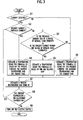
- FIG. 3 is a flowchart showing processes performed in the protection device.
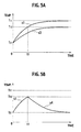
- FIG. 4A is a chart indicating variation of a temperature of a wire from in transit time from when a current starts flowing or is increasing in the wire; and FIG. 4B is a chart indicating variation of the same when the current becomes zero or decreases after the temperature is saturated.
- FIG. 5A is a chart indicating variation of the temperature of the wire from in transit time from when a current starts flowing or is increasing in the wire; and FIG. 5B is a chart indicating variation of the same when the current decreases before the temperature is saturated.
- FIG. 6 is an arc-related map stored in a third temperature estimation device.
- An embodiment of the present invention will be explained hereinafter with reference to the drawings. FIG. 1 is a circuit diagram of a load circuit in which a protection circuit is used. The load circuit may be used in a vehicle so that a battery provided in the vehicle to supplies power to a load, such as a bulb, a motor or the like.
- As shown in the same figure, the
load circuit 1 is provided between abattery 2 in a vehicle and aload 4, such as a bulb, a motor and the like. Theload circuit 1 has an electrical switch (switch) 3 such as a MOSFET to supply power from thebattery 2 to theload 4. - The
load circuit 1 further has an ammeter (a current detection device) 5 for detecting and measuring a current flowing to theload 4, and acontrol circuit 6 for controlling ON and OFF states of theelectrical switch 3. Here, thebattery 2 is electrically connected to theelectrical switch 3 by awire 7. In the same way, theelectrical switch 3 is electrically connected to theload 4 by thewire 7. Accordingly, in this embodiment, aprotection circuit 10 for the load circuit includes theelectrical switch 3, theammeter 5 and thecontrol circuit 6. - FIG. 2 is a functional block diagram showing a detailed configuration of the
control circuit 6. As seen in this figure, thecontrol circuit 6 comprises a rising/increasing temperature estimation device (a first temperature estimation device) 61, a falling/decreasing temperature estimation device (a second temperature estimation device) 62, an arc-induced rising/increasing temperature estimation device (a third temperature estimation device) 63, a present temperature estimation device (a fourth temperature estimation device) 64, atemperature determination device 65, and a switch control device (a shutoff control device) 66. - The rising/increasing
temperature estimation device 61 estimates a temperature increase of thewire 7 at a predetermined sampling rate (e.g. 5msec). The estimation is based on both a value of the current flowing to theload 4, as measured by theammeter 5 when the electrical switch is turned ON, and predetermined thermal properties (a thermal resistivity R and a thermal capacity C, as described below) of a conductor including thewire 7 and a contact conductor. - The falling/decreasing
temperature estimation device 62 estimates a decrease of temperature of thewire 7 in the predetermined sampling rate. The estimation is based on both an estimated present temperature of thewire 7 and the predetermined thermal properties. Here, the estimated present temperature is determined when theammeter 5 does not detect the current due to a disconnection between thewire 7 and the contact conductor in the circuit, when theammeter 5 cannot detect the current after the current is decreased, or when the current starts to decrease. - The temperature of the
wire 7 is occasionally increased by arcing which occurs just after the normal current in the load has recovered following a connection between thewire 7 and the contact conductor. The arc-inducedtemperature estimation device 63 estimates an arc-induced rising/increasing temperature of thewire 7 that is induced by the arcing, based on the current measured just before the normal current has been recovered. - The present
temperature estimation device 64 estimates a present temperature of thewire 7 by estimation that is based on temperatures estimated by the rising/increasingtemperature estimation device 61, the falling/decreasingtemperature estimation device 62, and the arc-induced rising/increasingtemperature estimation device 63. The presenttemperature estimation device 64 includes amemory 64a to store the estimated present temperature. - The
temperature determination device 65 compares the present temperature Tnow estimated by the presenttemperature estimation device 64 with a predetermined maximum allowable temperature (a predetermined threshold temperature), Tth. If thetemperature determination device 65 determines that Tnow is higher than Tth, thedevice 65 outputs a circuit-shutoff signal to theswitch control device 66. - The switch control device (shutoff control device) 66 receives the circuit-shutoff signal and then turns off the
electrical switch 3 so as to stop supplying power and protect a circuit. - The functional configuration of the
control circuit 6 as described above is related only to a configuration applied when the so-called rare-short circuit occurs in the load circuit, and description of the dead-short circuit configuration is omitted. - Next, estimation methods of the rising/increasing or falling/decreasing temperature by the first, second and third temperature estimation devices are explained below.
- The temperature of the
wire 7 increases by the current flowing therein, this temperature is determined from the formula (1) as follows;
wherein T1 is a temperature of the wire [°C]; T2 is an ambient temperature [°C]; i is a current [A]; r is an electric resistance in the conductor [Ω]; R is a thermal resistance of the conductor [°C/W]; C is a heat capacity of the conductor [J/°C or W·sec/°C]; and t is transit time [sec]. - In the above formula, the ambient temperature T2 is an initial temperature of the
wire 7 when theelectrical switch 3 is turn on. For example, T2 may be 25°C in normal circumstances and it may be 85°C in an engine compartment where an engine in a vehicle is running. The current i is determined by a measurement obtained from theammeter 5. The electrical resistance r is a resistance of the conductor including thewire 7, and is constant. The thermal resistance R is a value indicating the conductor's ability to conduct heat. The thermal resistance R depends on intrinsic properties such as the conductor's material, thickness, and shape. The heat capacity C represents an amount of heat which is required to increase the temperature of the conductor by 1°C. The heat capacity also depends on the intrinsic properties of the conductor. - Consequently, if the current i, and transit time t, are determined the present temperature is estimated by the formula (1).
- If the
ammeter 5 does not detect a current or detects that the current decreases, the temperature T1 is determined by taking into account heat radiated from the conductor by a formula (2) as follows;
- In the formula (2), the ambient temperature T2 is the temperature of the
wire 7 determined when theammeter 5 does not detect the current or detects that the current is decreasing. If the temperature of thewire 7 is not saturated, the current i in the formula (2) is defined as a current which would be flowing at this temperature which is assumed to be a saturated temperature in the formula (1). If the temperature of thewire 7 is saturated when theammeter 5 does not detect the current or detects that the current is decreased, the current i in the formula (2) is defined as a current which is measured just before theammeter 5 does not detect the current or detects that the current has decreased. Consequently, if the current i and transit time, t, are determined as described above, the present temperature of thewire 7 is estimated by the formula (2). - The
memory 64a preliminarily stores data as a arc-related map shown in FIG. 6, which includes a temporal high current i which flows just before the normal current is recovered following connection of thewire 7 with the contact conductor, and a temperature increment Q(i) caused by the temporal high current. Consequently, when the temporal high current i is measured before the normal current is recovered following connection of thewire 7 with the contact conductor, the arc-inducedtemperature estimation device 63 finds the temperature increment Q(i) from the data, based on the measured temporal high current i , and estimates the arc-induced rising/increasing temperature of thewire 7 based on the following formula (3);
where the ambient temperature T2 is determined when the normal current is recovered following connection of thewire 7 with the contact conductor. - Next, an operation of the
load circuit 1, according to the embodiment described above, is explained hereinafter with reference to the flowchart shown in FIG. 3. Here, each process shown in this chart is carried out periodically in a predetermined sampling rate (e.g. 5msec). - First, in step S1, the
ammeter 5 determines if a load current is flowing to theload 4. In other words, it is determined if the load current is flowing after theelectrical switch 3 is turned on and an electrical connection between thebattery 2 and theload 4 is established. - If the
ammeter 5 detects the flow of the load current (i.e. "YES" in step S1), in step S2 the load current presently measured is compared with the load current previously measured in a previous sampling sequence. - If the presently measured current is higher than or equal to the previously measured current (i.e. "YES" in the step S2), that is, if it is determined that the present current flowing to the
load 4 has been increased or it is constant, the firsttemperature estimation device 61 starts a timer to record the transit time and estimates the temperature of thewire 7 using the formula (1) (step 4). This estimation is carried out based on both the current measured by theammeter 5 and the transit time counted by the timer. Meanwhile, the ambient temperature T2 is set to be 25 °C as an initial value, for example. - In step S7, the fourth
temperature estimation device 64 stores the temperature T1 estimated in the step S4 in thememory 64a as the estimated present temperature of thewire 7, Tnow. - In step S8, the
temperature determination device 65 compares Tnow stored in thememory 64a with the predetermined allowable temperature Tth. Then, if Tnow is less than or equal to Tth, the process returns to the step S 1 (i.e. "YES" in the step S8). - According to the above steps, if the current flowing to the
load 4 is increasing or stable, the successive steps (S1, S2, S4, and S7) are repeated and the temperature of thewire 7 is saturated to temperature T1 as related in the formula (4) described below, which is obtained from the formula (1) by substituting an infinite value in the transit time thereof;
- If the so-called rare-short circuit occurs in the
load circuit 1 and the current flowing to theload 4 is increased, the temperature of thewire 7 is increased and Tnow will exceed Tth. In this case, the decision in the step S8 becomes "NO". Accordingly, theswitch control device 66 turns off theelectrical switch 3 so as to stop supplying the power to the circuit for protection device. - If the presently measured current of the present sampling is less than the previously measured current in the previous sampling (i.e. "NO" in the step S2), it is determined in step S3 if the previously measured current is outside of the range of current in the normal operation and the presently measured current is within the range of current in the normal operation. If arcing has occurred, the answer becomes "YES" and the arc-induced rising/increasing
temperature estimation device 63 estimates the arc-induced rising temperature, based on the formula (3) described above with reference to the arc-related map (step S5). That is, the temperature increment Q(i) is determined by applying the measured current, which flows just before the normal current is recovered, to the arc-related map. - In the step S7, the present
temperature estimation device 64 adds the estimated temperature increment Q(i) resulting from the above process, to the stored temperature of thewire 7 in thememory 64a, thereby the temperature of thewire 7 is updated. In other words, the temperature stored in thememory 64a in the previous sampling sequence is regarded as the ambient temperature T2, and based on the formula (3) the sum of T2 plus the temperature increment Q(i) becomes the present temperature T1 of the wire. Accordingly, this T1 is stored in thememory 64a as the estimated present temperature Tnow of thewire 7. - Next, if the estimated temperature Tnow is less than or equal to the allowable temperature (i.e. "YES" in step S8), the process returns to the step S1. On the contrary, if "No" is determined in the step S8, the
switch control device 66 turns off theelectrical switch 3 to shut off the power for the circuit to prevent theload circuit 1 from being overheated. - If "NO" is determined in the step S3, that is, if a condition where the previously measured current is outside of the range of current in the normal operation and the presently measured current is within the range of current in the normal operation (in other words, the condition where the current is steadly decreased without any increase of the current by arcing or the like and "NO" is determined in the step S 1 (i.e. no current flowing in the load 4), is not satisfied) the process proceeds to step S6.
- In the step S6, the falling/decreasing
temperature estimation device 62 initially resets and restarts the timer. Further, it estimates the present temperature of thewire 7, T1, from the formula (2) by substituting the transit time, t, counted by the timer. Here, as described above, the current i used in the formula (2) is defined as a current which would be flowing at this temperature which is assumed as a saturated temperature. If the temperature of thewire 7 is saturated when theammeter 5 does not detect the current or detects that the current is decreased, the current i in the formula (2) is defined as a current which is measured just before theammeter 5 does not detect the current or detects that the current has decreased. - Hereinafter, the current i in the formula (2) will be explained in detail. Now it is assumed that the ambient temperature (as an initial temperature of the wire 7) is T21. Next, when a constant current i1 starts flowing continuously, the temperature of the
wire 7 starts to increase and it is finally saturated. FIG. 4a shows this behavior of the temperature by a curve s1. As seen in this figure, the temperature gradually increases from T21 and is finally saturated at a temperature T11. - Next, if the
ammeter 5 does not detect the current or detects that the current decreases after the temperature of thewire 7 is already saturated to the temperature T11, a current which saturates the temperature of thewire 7 to a temperature T11, and which is measured just before theammeter 5 does not detect the current or detect that the current is decreased, that is, the current i1 is used as "i" in the formula (2). In this case, as seen in FIG. 4b, the temperature of thewire 7 starts gradually decreasing as a curve s2 obtained by vertical flip of the curve s1. Finally, the temperature is fallen asymptotically to the ambient temperature T21. - If the
ammeter 5 does not detect the current or detects that the current is decreased when the temperature of thewire 7 is not saturated yet, that is, as shown in FIG. 5a, if the current is not detected or is decreased at time t1 before the temperature is saturated to the temperature T11, the current, which saturates the temperature of thewire 7 to an instant temperature, is set to be "i" in the formula (2). That is, the current i2 which saturates the temperature of thewire 7 to the instant temperature T12, is estimated (c.f. a curve s3), then this current i2 is used as "i" in the formula (2). - Accordingly, the heat radiation property follows a curve obtained by vertical flip of the curve s3 and the temperature of the
wire 7 decreases as a curve s4 shown in FIG. 5b. - Further, if the falling/decreasing temperature is estimated based on the formula (2) in the step S6, the estimated present temperature Tnow, which is stored in the
memory 64a of the fourthtemperature estimation device 64, is updated instep 7. - That is, the estimated present temperature of the
wire 7 Tnow, which is determined by taking into account all of the rising/increasing temperature when the current is increasing, the arc-induced rising/increasing temperature when the arcing occurs, and the heat radiation when the load current is zero or is decreased, is stored in thememory 64a. In the step S8, this estimated present temperature Tnow is compared with the allowable temperature Tth. If Tnow is higher than or equal to Tth, theelectrical switch 3 is turned off to shut off the power for the load circuit. Consequently, if the rare-short circuit occurs and the temperature of thewire 7 increases, the power for the load circuit can be immediately shut off. - According to the embodiment of the protection device for the load circuit, when the current flowing to the
load 4 is increased, it estimates the temperature of thewire 7 based on the formula (1), when the current is zero or the current is decreased, it estimates the temperature of thewire 7 based on the formula (2). When the arcing occurs, it estimates the arc-induced rising/increasing temperature based on the formula (3). Consequently, the device comprehensively estimates the present temperature of thewire 7 from these temperatures described above. - As soon as the estimated present temperature of the
wire 7 Tnow achieves the allowable temperature Tth at which a smoke emission from thewire 7 and burnout thereof is induced in the load circuit, theelectrical switch 3 is turned off to protect the load circuit. IN more detail, since the protection device estimates the present temperature of thewire 7 based on the intrinsic properties of the wire and determines if the power for the load circuit should be shut off based on the estimated present temperature, it can positively shut off the power to protect the load circuit from emitting smoke from the wire and burnout thereof. Further, the device can prevent unexpected shutoff of the power for theload circuit 1 due to quite low heat generated in thewire 7 by the current flowing to theload circuit 1. - Further, when the current flowing to the
load 4 becomes zero or the current starts to decrease, the protection device precisely estimates the falling/decreasing temperature due to the heat radiated from the wire because this estimation is carried out based on the formula (2) in which the current, which is required to be saturated to the temperature just before the current has varied, is used. Consequently, even when the rare-short circuit accidentally occurs, the protection device can positively shut off the power for the load circuit before smoke is emitted from thewire 7 and subsequent burnout thereof. - The protection device for the load circuit by the present invention is explained by the embodiment as shown in the figures. However, the present invention is not limited by the embodiment and each configuration in the present invention may be replaced any one which has same function. For example, the embodiment described above is used for the
load circuit 1 for bulbs, motors and the like in vehicles, however, it may be used for other load circuits.
Claims (4)
- A protection device for a load circuit including a power supply, a switch and a load, comprising:a current detection device detecting and measuring a current in a conductor connected between the power supply and the load;a first temperature estimation device that estimates a rising temperature of the conductor, when the current is detected by the current detection device;a second temperature estimation device that estimates a falling temperature of the conductor when the current detection device fails to detect the current or detects that the current is being decreased,a third temperature estimation device that estimates an arc-induced rising temperature of the conductor that is induced by arcing that occurs just after the current has returned to a normal current;a fourth temperature estimation device that estimates a present temperature of the conductor based on the estimated rising, falling, and arc-induced rising temperatures;a temperature determination device that determines whether the present temperature of the conductor estimated by the fourth temperature estimation device exceeds a predetermined threshold temperature;a shutoff control device that shuts off power to the load circuit when the temperature determination device determines that the present temperature of the conductor exceeds the predetermined threshold temperature, andwherein the rising temperature is estimated base on both the current measured by the current detection device and thermal properties of the conductor;
the falling temperature of the conductor is estimated based on the thermal properties of the conductor; and
the arc-induced rising temperature is estimated based on the current just before the current returns to the normal current. - The protection device according to claim 1,
wherein the thermal properties are thermal resistivity R and heat capacity C. - The protection device according to claim 2,
wherein the rising temperature estimated by the first temperature estimation device is determined by the following formula;
- The protection device according to claim 2,
wherein the falling temperature estimated by the second temperature estimation device is determined by the following formula;
Applications Claiming Priority (1)
| Application Number | Priority Date | Filing Date | Title |
|---|---|---|---|
| JP2006123544A JP4762044B2 (en) | 2006-04-27 | 2006-04-27 | Load circuit protection device |
Publications (3)
| Publication Number | Publication Date |
|---|---|
| EP1850438A2 true EP1850438A2 (en) | 2007-10-31 |
| EP1850438A3 EP1850438A3 (en) | 2016-11-09 |
| EP1850438B1 EP1850438B1 (en) | 2020-10-28 |
Family
ID=38293120
Family Applications (1)
| Application Number | Title | Priority Date | Filing Date |
|---|---|---|---|
| EP07008524.6A Ceased EP1850438B1 (en) | 2006-04-27 | 2007-04-26 | Protection device for load circuits |
Country Status (3)
| Country | Link |
|---|---|
| US (1) | US7640080B2 (en) |
| EP (1) | EP1850438B1 (en) |
| JP (2) | JP4762044B2 (en) |
Cited By (13)
| Publication number | Priority date | Publication date | Assignee | Title |
|---|---|---|---|---|
| WO2009119002A1 (en) * | 2008-03-24 | 2009-10-01 | Yazaki Corporation | Protection apparatus of load circuit |
| WO2009119001A1 (en) * | 2008-03-28 | 2009-10-01 | Yazaki Corporation | Protection apparatus of load circuit |
| FR2936468A1 (en) * | 2008-09-26 | 2010-04-02 | Peugeot Citroen Automobiles Sa | Motor vehicle e.g. car, fabricating method, involves calculating value of temperature in each of tracks based on values of characteristic quantities of cable, selecting cable based on calculated value, and placing cable in electric network |
| WO2011005254A1 (en) * | 2009-07-08 | 2011-01-13 | Abb Research Ltd | Bus condition monitoring system |
| EP2276135A1 (en) | 2008-04-15 | 2011-01-19 | Yazaki Corporation | Load circuit protection device |
| EP2439828A1 (en) | 2009-06-04 | 2012-04-11 | Yazaki Corporation | Protection device for load circuits |
| WO2012077297A1 (en) * | 2010-12-09 | 2012-06-14 | Yazaki Corporation | Load circuit disconnection detector |
| CN103066571A (en) * | 2012-12-21 | 2013-04-24 | 广西诺斯贝电气有限公司 | Overload protection method and device of combination switch |
| EP2768286A3 (en) * | 2013-02-18 | 2016-02-24 | Panasonic Intellectual Property Management Co., Ltd. | Lighting device and lighting fixture |
| CN104269818B (en) * | 2008-06-13 | 2017-08-18 | 矢崎总业株式会社 | The protection device of load circuit |
| EP3249658A3 (en) * | 2016-05-24 | 2018-03-28 | Yazaki Systems Technologies GmbH | Vehicle wiring harness, assembly comprising such a vehicle wire harness and method |
| WO2020099412A1 (en) * | 2018-11-13 | 2020-05-22 | Brose Fahrzeugteile SE & Co. Kommanditgesellschaft, Würzburg | Electric motor assembly having fault identification, and method for operating an electric motor assembly |
| CN114460997A (en) * | 2021-12-24 | 2022-05-10 | 珠海格力电器股份有限公司 | Circuit for improving temperature detection accuracy, temperature detection circuit, method and device |
Families Citing this family (36)
| Publication number | Priority date | Publication date | Assignee | Title |
|---|---|---|---|---|
| US7966587B2 (en) * | 2006-05-18 | 2011-06-21 | Renesas Electronics Corporation | Information storage medium on which is stored an interconnection program, interconnection method, interconnection apparatus, and semiconductor device |
| US7880340B2 (en) * | 2007-04-27 | 2011-02-01 | Advanced Micro Devices, Inc. | Radiation-triggered semiconductor shutdown device |
| JP5323451B2 (en) * | 2007-11-16 | 2013-10-23 | 古河電気工業株式会社 | Power supply device and power supply method |
| JP4624400B2 (en) * | 2007-11-19 | 2011-02-02 | 株式会社オートネットワーク技術研究所 | Electric wire protection method and electric wire protection device for vehicle |
| KR100952222B1 (en) * | 2007-12-18 | 2010-04-09 | 주식회사 에너테크 | Arc current breaker and method |
| JP5158948B2 (en) * | 2008-03-11 | 2013-03-06 | 矢崎総業株式会社 | Electrical junction box, power supply cutoff method, and program |
| JP2009261088A (en) * | 2008-04-15 | 2009-11-05 | Yazaki Corp | Device for protecting load circuit |
| JP5390837B2 (en) * | 2008-11-14 | 2014-01-15 | 矢崎総業株式会社 | Load circuit protection device |
| JP5271619B2 (en) * | 2008-06-30 | 2013-08-21 | 矢崎総業株式会社 | Load circuit protection device |
| DE102008039334B4 (en) * | 2008-08-22 | 2016-01-14 | Airbus Defence and Space GmbH | Method and device for optimized energy management |
| JP2010158108A (en) * | 2008-12-26 | 2010-07-15 | Yazaki Corp | Protector for load circuits |
| US8504213B2 (en) * | 2009-06-26 | 2013-08-06 | General Electric Company | Regulation of generating plant |
| DE112010003777B4 (en) * | 2009-09-25 | 2021-01-14 | Autonetworks Technologies, Ltd. | Power supply controller |
| JP5660358B2 (en) | 2009-09-25 | 2015-01-28 | 株式会社オートネットワーク技術研究所 | Power supply control device |
| JP5482055B2 (en) * | 2009-09-25 | 2014-04-23 | 株式会社オートネットワーク技術研究所 | Power supply control device |
| JP5684871B2 (en) * | 2010-02-26 | 2015-03-18 | 矢崎総業株式会社 | Load circuit protection device |
| JP5639868B2 (en) * | 2010-12-06 | 2014-12-10 | 矢崎総業株式会社 | Load circuit protection device |
| JP5944729B2 (en) | 2012-04-24 | 2016-07-05 | 矢崎総業株式会社 | Protection device for energization circuit |
| JP5876367B2 (en) * | 2012-04-24 | 2016-03-02 | 矢崎総業株式会社 | Protection device for energization circuit |
| US9129510B2 (en) * | 2012-11-28 | 2015-09-08 | Abb Technology Ag | Monitoring operating condition of electrical component |
| CN103247999B (en) * | 2013-04-25 | 2015-11-18 | 国家电网公司 | A kind of emulation mode that adopts is to realize the electrical fuse device of fuse real physical characteristics |
| CN103248001A (en) * | 2013-04-25 | 2013-08-14 | 国家电网公司 | Electronic type low-pressure distribution transformer fuse case provided with inverse-time characteristic |
| JP6128055B2 (en) | 2014-05-22 | 2017-05-17 | 住友電装株式会社 | Wire protector |
| JP6247199B2 (en) | 2014-12-09 | 2017-12-13 | 株式会社トンボ鉛筆 | Film transfer tool |
| JP6148266B2 (en) * | 2015-02-16 | 2017-06-14 | ファナック株式会社 | Motor control device with function to detect miswiring |
| JP6304072B2 (en) * | 2015-02-27 | 2018-04-04 | 株式会社オートネットワーク技術研究所 | Shut-off device, shut-off method, and computer program |
| JP6339617B2 (en) | 2016-03-28 | 2018-06-06 | 矢崎総業株式会社 | Power shut-off device |
| JP6846244B2 (en) | 2017-03-13 | 2021-03-24 | 矢崎総業株式会社 | Wire protection device |
| JP6882023B2 (en) | 2017-03-13 | 2021-06-02 | 矢崎総業株式会社 | Wire protection device |
| JP6808547B2 (en) | 2017-03-13 | 2021-01-06 | 矢崎総業株式会社 | Wire protection device and control method of wire protection device |
| US10690704B2 (en) * | 2017-05-18 | 2020-06-23 | I.D. Systems, Inc. | Multi-access control and multi-relay systems and methods |
| JP7095856B2 (en) | 2017-07-04 | 2022-07-05 | 株式会社トンボ鉛筆 | Coating film transfer tool |
| WO2019008687A1 (en) | 2017-07-04 | 2019-01-10 | 株式会社トンボ鉛筆 | Coating film transfer tool |
| US12353199B2 (en) * | 2020-01-17 | 2025-07-08 | Nippon Telegraph And Telephone Corporation | Communication apparatus and temperature monitoring method |
| JP7605603B2 (en) * | 2020-09-23 | 2024-12-24 | 株式会社日本クライメイトシステムズ | Vehicle air conditioning system |
| DE102022132531A1 (en) | 2022-12-07 | 2024-06-13 | Cariad Se | Method and control circuit for operating a switch element of an electrical component to prevent it from overheating due to electrical heat loss, and electrical component with the control circuit |
Family Cites Families (23)
| Publication number | Priority date | Publication date | Assignee | Title |
|---|---|---|---|---|
| US5418677A (en) * | 1990-12-28 | 1995-05-23 | Eaton Corporation | Thermal modeling of overcurrent trip during power loss |
| US5644510A (en) * | 1994-11-25 | 1997-07-01 | General Electric Company | Apparatus and method for motor overload protection using an elapsed-time signal for enabling computation of motor temperature data independently of temporary power interruption |
| JP3127768B2 (en) * | 1995-02-28 | 2001-01-29 | 日新電機株式会社 | Monitoring method of electric wire temperature |
| JP3908805B2 (en) * | 1996-06-20 | 2007-04-25 | ブラザー工業株式会社 | Motor temperature control device |
| US5875087A (en) * | 1996-08-08 | 1999-02-23 | George A. Spencer | Circuit breaker with integrated control features |
| JP3568722B2 (en) * | 1997-01-13 | 2004-09-22 | 日野自動車株式会社 | Overcurrent cutoff circuit |
| US6167525A (en) * | 1997-02-26 | 2000-12-26 | Pirelli Cavi E Sistemi S.P.A. | Method and system for analysis of electric power transmission link status |
| US5861610A (en) * | 1997-03-21 | 1999-01-19 | Micro Weiss Electronics | Heater wire with integral sensor wire and improved controller for same |
| JP3465569B2 (en) * | 1998-01-26 | 2003-11-10 | 日産自動車株式会社 | Electric vehicle overload prevention device |
| JP3656412B2 (en) * | 1998-07-03 | 2005-06-08 | 株式会社日立製作所 | Vehicle power control device |
| JP2000299922A (en) * | 1999-02-12 | 2000-10-24 | Yazaki Corp | Power supply control device and power supply control method |
| JP2000299924A (en) * | 1999-02-14 | 2000-10-24 | Yazaki Corp | Power supply control device and method |
| JP4153624B2 (en) * | 1999-07-29 | 2008-09-24 | 太平洋精工株式会社 | Fuse element with rare short judgment function |
| FR2802019B1 (en) * | 1999-12-06 | 2002-01-18 | Schneider Electric Ind Sa | THERMAL PROTECTION RELAY |
| JP2002010471A (en) * | 2000-06-19 | 2002-01-11 | Yazaki Corp | Overcurrent interrupter |
| JP4443744B2 (en) * | 2000-09-04 | 2010-03-31 | 太平洋精工株式会社 | Rare short judging device and rare short judging method |
| JP3914004B2 (en) * | 2001-05-25 | 2007-05-16 | 矢崎総業株式会社 | Overcurrent detection / protection device for semiconductor elements |
| US6870720B2 (en) * | 2002-01-25 | 2005-03-22 | Pacific Engineering Corp. | Device and method for determining intermittent short circuit |
| US7019951B2 (en) * | 2004-06-03 | 2006-03-28 | Rockwell Automation Technologies, Inc. | Extended trip range motor control system and method |
| US7394629B2 (en) * | 2003-10-16 | 2008-07-01 | Rockwell Automation Technologies, Inc. | Motor overload tripping system and method with multi-function circuit interrupter |
| US6903533B1 (en) * | 2003-12-16 | 2005-06-07 | Motorola, Inc. | Power fault battery protection circuit |
| US7161775B2 (en) * | 2004-05-21 | 2007-01-09 | Eaton Corporation | Arc fault circuit breaker and apparatus for detecting wet track arc fault |
| US7268989B2 (en) * | 2005-04-11 | 2007-09-11 | Eaton Corporation | Arc fault circuit interrupter for a compressor load |
-
2006
- 2006-04-27 JP JP2006123544A patent/JP4762044B2/en not_active Expired - Fee Related
-
2007
- 2007-04-13 US US11/783,931 patent/US7640080B2/en not_active Expired - Fee Related
- 2007-04-26 EP EP07008524.6A patent/EP1850438B1/en not_active Ceased
-
2010
- 2010-02-26 JP JP2010042802A patent/JP5377362B2/en not_active Expired - Fee Related
Cited By (31)
| Publication number | Priority date | Publication date | Assignee | Title |
|---|---|---|---|---|
| WO2009119002A1 (en) * | 2008-03-24 | 2009-10-01 | Yazaki Corporation | Protection apparatus of load circuit |
| US20110019325A1 (en) * | 2008-03-24 | 2011-01-27 | Yazaki Corporation | Protection apparatus of load circuit |
| CN101978568A (en) * | 2008-03-24 | 2011-02-16 | 矢崎总业株式会社 | Protection device for load circuit |
| CN101981775A (en) * | 2008-03-28 | 2011-02-23 | 矢崎总业株式会社 | Protection apparatus of load circuit |
| WO2009119001A1 (en) * | 2008-03-28 | 2009-10-01 | Yazaki Corporation | Protection apparatus of load circuit |
| CN101981775B (en) * | 2008-03-28 | 2013-07-10 | 矢崎总业株式会社 | Protection apparatus of load circuit |
| US8432657B2 (en) | 2008-03-28 | 2013-04-30 | Yazaki Corporation | Protection apparatus of load circuit |
| US8437110B2 (en) | 2008-04-15 | 2013-05-07 | Yazaki Corporation | Protection apparatus of load circuit |
| EP2276135A1 (en) | 2008-04-15 | 2011-01-19 | Yazaki Corporation | Load circuit protection device |
| EP2717403A1 (en) * | 2008-04-15 | 2014-04-09 | Yasaki Corporation | Protection apparatus of load circuit |
| EP2276135A4 (en) * | 2008-04-15 | 2013-06-26 | Yazaki Corp | LOAD CIRCUIT PROTECTION DEVICE |
| CN104269818B (en) * | 2008-06-13 | 2017-08-18 | 矢崎总业株式会社 | The protection device of load circuit |
| FR2936468A1 (en) * | 2008-09-26 | 2010-04-02 | Peugeot Citroen Automobiles Sa | Motor vehicle e.g. car, fabricating method, involves calculating value of temperature in each of tracks based on values of characteristic quantities of cable, selecting cable based on calculated value, and placing cable in electric network |
| US8693156B2 (en) | 2009-06-04 | 2014-04-08 | Yazaki Corporation | Protection apparatus for load circuit |
| EP2439828A4 (en) * | 2009-06-04 | 2017-07-12 | Yazaki Corporation | Protection device for load circuits |
| EP2439828A1 (en) | 2009-06-04 | 2012-04-11 | Yazaki Corporation | Protection device for load circuits |
| WO2011005254A1 (en) * | 2009-07-08 | 2011-01-13 | Abb Research Ltd | Bus condition monitoring system |
| CN102474130A (en) * | 2009-07-08 | 2012-05-23 | Abb研究有限公司 | Bus condition monitoring system |
| CN102474130B (en) * | 2009-07-08 | 2014-10-15 | Abb研究有限公司 | Bus condition monitoring system |
| US8981945B2 (en) * | 2009-07-08 | 2015-03-17 | Abb Research Ltd. | Bus condition monitoring system |
| US20120194344A1 (en) * | 2009-07-08 | 2012-08-02 | Abb Research Ltd | Bus condition monitoring system |
| CN103262374A (en) * | 2010-12-09 | 2013-08-21 | 矢崎总业株式会社 | Load circuit disconnection detector |
| WO2012077297A1 (en) * | 2010-12-09 | 2012-06-14 | Yazaki Corporation | Load circuit disconnection detector |
| US9083179B2 (en) | 2010-12-09 | 2015-07-14 | Yazaki Corporation | Load circuit disconnection detector |
| CN103262374B (en) * | 2010-12-09 | 2015-11-25 | 矢崎总业株式会社 | Load circuit disconnection detector |
| CN103066571B (en) * | 2012-12-21 | 2015-06-03 | 广西诺思贝电气股份有限公司 | Overload protection method and device of combination switch |
| CN103066571A (en) * | 2012-12-21 | 2013-04-24 | 广西诺斯贝电气有限公司 | Overload protection method and device of combination switch |
| EP2768286A3 (en) * | 2013-02-18 | 2016-02-24 | Panasonic Intellectual Property Management Co., Ltd. | Lighting device and lighting fixture |
| EP3249658A3 (en) * | 2016-05-24 | 2018-03-28 | Yazaki Systems Technologies GmbH | Vehicle wiring harness, assembly comprising such a vehicle wire harness and method |
| WO2020099412A1 (en) * | 2018-11-13 | 2020-05-22 | Brose Fahrzeugteile SE & Co. Kommanditgesellschaft, Würzburg | Electric motor assembly having fault identification, and method for operating an electric motor assembly |
| CN114460997A (en) * | 2021-12-24 | 2022-05-10 | 珠海格力电器股份有限公司 | Circuit for improving temperature detection accuracy, temperature detection circuit, method and device |
Also Published As
| Publication number | Publication date |
|---|---|
| JP5377362B2 (en) | 2013-12-25 |
| JP2010172191A (en) | 2010-08-05 |
| JP4762044B2 (en) | 2011-08-31 |
| EP1850438B1 (en) | 2020-10-28 |
| US7640080B2 (en) | 2009-12-29 |
| US20070253132A1 (en) | 2007-11-01 |
| JP2007295776A (en) | 2007-11-08 |
| EP1850438A3 (en) | 2016-11-09 |
Similar Documents
| Publication | Publication Date | Title |
|---|---|---|
| US7640080B2 (en) | Protection device for load circuits | |
| EP1993182A2 (en) | Protection device for load circuits | |
| US8767367B2 (en) | Wire protection method and wire protection device | |
| US11114711B2 (en) | Rapid low-temperature self-heating method and device for battery | |
| US8437110B2 (en) | Protection apparatus of load circuit | |
| JP5274254B2 (en) | Method and apparatus for detecting overload in a tool | |
| JP4275078B2 (en) | Battery current limit control method | |
| US9746526B2 (en) | Battery cell unit and method for determining a complex impedance of a battery cell arranged in a battery cell unit | |
| US9293907B2 (en) | Protective device for load circuit | |
| US20110019325A1 (en) | Protection apparatus of load circuit | |
| CA2431159A1 (en) | Battery pack charging system | |
| US12341165B2 (en) | Method for monitoring a battery system | |
| CN111584816A (en) | Protection device, battery, motor vehicle, and method for shutting down battery cells | |
| WO2018168981A1 (en) | Current detector | |
| US8432657B2 (en) | Protection apparatus of load circuit | |
| KR20160040886A (en) | Apparatus and method for detecting degradation of switch | |
| US6380717B2 (en) | Device and method for controlling charging of secondary battery | |
| JPH09266634A (en) | Secondary battery protection circuit | |
| US8751175B2 (en) | Method and device for overload detection in battery-operated devices having an electric motor | |
| KR20200007295A (en) | Inverter apparatus of electric vehicle | |
| WO2016157731A1 (en) | Secondary battery status estimation device and status estimation method | |
| US11283115B2 (en) | Method for determining a status of the thermal connection of at least one component within an electrical energy storage system to a heat source or heat sink | |
| WO2018179855A1 (en) | Battery control device | |
| JP2017147844A (en) | Power supply | |
| JP3817863B2 (en) | Alkaline battery charger |
Legal Events
| Date | Code | Title | Description |
|---|---|---|---|
| PUAI | Public reference made under article 153(3) epc to a published international application that has entered the european phase |
Free format text: ORIGINAL CODE: 0009012 |
|
| 17P | Request for examination filed |
Effective date: 20070426 |
|
| AK | Designated contracting states |
Kind code of ref document: A2 Designated state(s): AT BE BG CH CY CZ DE DK EE ES FI FR GB GR HU IE IS IT LI LT LU LV MC MT NL PL PT RO SE SI SK TR |
|
| AX | Request for extension of the european patent |
Extension state: AL BA HR MK YU |
|
| PUAL | Search report despatched |
Free format text: ORIGINAL CODE: 0009013 |
|
| AK | Designated contracting states |
Kind code of ref document: A3 Designated state(s): AT BE BG CH CY CZ DE DK EE ES FI FR GB GR HU IE IS IT LI LT LU LV MC MT NL PL PT RO SE SI SK TR |
|
| AX | Request for extension of the european patent |
Extension state: AL BA HR MK RS |
|
| RIC1 | Information provided on ipc code assigned before grant |
Ipc: H02H 6/00 20060101AFI20161005BHEP Ipc: H02H 7/22 20060101ALI20161005BHEP Ipc: G01K 7/42 20060101ALI20161005BHEP Ipc: H02H 1/00 20060101ALI20161005BHEP Ipc: H02H 5/04 20060101ALI20161005BHEP Ipc: H01H 83/20 20060101ALI20161005BHEP Ipc: G01K 3/00 20060101ALI20161005BHEP |
|
| AKX | Designation fees paid |
Designated state(s): DE FR GB |
|
| AXX | Extension fees paid |
Extension state: AL Extension state: BA Extension state: RS Extension state: MK Extension state: HR |
|
| REG | Reference to a national code |
Ref country code: DE Ref legal event code: R079 Ref document number: 602007060731 Country of ref document: DE Free format text: PREVIOUS MAIN CLASS: H02H0006000000 Ipc: H01H0011000000 |
|
| GRAP | Despatch of communication of intention to grant a patent |
Free format text: ORIGINAL CODE: EPIDOSNIGR1 |
|
| STAA | Information on the status of an ep patent application or granted ep patent |
Free format text: STATUS: GRANT OF PATENT IS INTENDED |
|
| RIC1 | Information provided on ipc code assigned before grant |
Ipc: H01H 11/00 20060101AFI20200703BHEP Ipc: H02H 6/00 20060101ALI20200703BHEP Ipc: H02H 7/22 20060101ALI20200703BHEP Ipc: G01K 3/00 20060101ALI20200703BHEP Ipc: H01H 83/20 20060101ALI20200703BHEP Ipc: H02H 1/00 20060101ALI20200703BHEP Ipc: G01K 7/42 20060101ALI20200703BHEP Ipc: H02H 5/04 20060101ALI20200703BHEP |
|
| INTG | Intention to grant announced |
Effective date: 20200729 |
|
| GRAS | Grant fee paid |
Free format text: ORIGINAL CODE: EPIDOSNIGR3 |
|
| GRAA | (expected) grant |
Free format text: ORIGINAL CODE: 0009210 |
|
| STAA | Information on the status of an ep patent application or granted ep patent |
Free format text: STATUS: THE PATENT HAS BEEN GRANTED |
|
| AK | Designated contracting states |
Kind code of ref document: B1 Designated state(s): DE FR GB |
|
| REG | Reference to a national code |
Ref country code: GB Ref legal event code: FG4D |
|
| REG | Reference to a national code |
Ref country code: DE Ref legal event code: R096 Ref document number: 602007060731 Country of ref document: DE |
|
| REG | Reference to a national code |
Ref country code: DE Ref legal event code: R097 Ref document number: 602007060731 Country of ref document: DE |
|
| PLBE | No opposition filed within time limit |
Free format text: ORIGINAL CODE: 0009261 |
|
| STAA | Information on the status of an ep patent application or granted ep patent |
Free format text: STATUS: NO OPPOSITION FILED WITHIN TIME LIMIT |
|
| 26N | No opposition filed |
Effective date: 20210729 |
|
| GBPC | Gb: european patent ceased through non-payment of renewal fee |
Effective date: 20210426 |
|
| PG25 | Lapsed in a contracting state [announced via postgrant information from national office to epo] |
Ref country code: GB Free format text: LAPSE BECAUSE OF NON-PAYMENT OF DUE FEES Effective date: 20210426 Ref country code: FR Free format text: LAPSE BECAUSE OF NON-PAYMENT OF DUE FEES Effective date: 20210430 |
|
| PGFP | Annual fee paid to national office [announced via postgrant information from national office to epo] |
Ref country code: DE Payment date: 20220302 Year of fee payment: 16 |
|
| REG | Reference to a national code |
Ref country code: DE Ref legal event code: R119 Ref document number: 602007060731 Country of ref document: DE |
|
| PG25 | Lapsed in a contracting state [announced via postgrant information from national office to epo] |
Ref country code: DE Free format text: LAPSE BECAUSE OF NON-PAYMENT OF DUE FEES Effective date: 20231103 |