EP1850146A1 - Arriving direction estimator - Google Patents
Arriving direction estimator Download PDFInfo
- Publication number
- EP1850146A1 EP1850146A1 EP05719250A EP05719250A EP1850146A1 EP 1850146 A1 EP1850146 A1 EP 1850146A1 EP 05719250 A EP05719250 A EP 05719250A EP 05719250 A EP05719250 A EP 05719250A EP 1850146 A1 EP1850146 A1 EP 1850146A1
- Authority
- EP
- European Patent Office
- Prior art keywords
- incoming direction
- sensors
- sin
- estimation apparatus
- signal
- Prior art date
- Legal status (The legal status is an assumption and is not a legal conclusion. Google has not performed a legal analysis and makes no representation as to the accuracy of the status listed.)
- Granted
Links
Images




Classifications
-
- G—PHYSICS
- G01—MEASURING; TESTING
- G01S—RADIO DIRECTION-FINDING; RADIO NAVIGATION; DETERMINING DISTANCE OR VELOCITY BY USE OF RADIO WAVES; LOCATING OR PRESENCE-DETECTING BY USE OF THE REFLECTION OR RERADIATION OF RADIO WAVES; ANALOGOUS ARRANGEMENTS USING OTHER WAVES
- G01S13/00—Systems using the reflection or reradiation of radio waves, e.g. radar systems; Analogous systems using reflection or reradiation of waves whose nature or wavelength is irrelevant or unspecified
- G01S13/02—Systems using reflection of radio waves, e.g. primary radar systems; Analogous systems
- G01S13/06—Systems determining position data of a target
- G01S13/42—Simultaneous measurement of distance and other co-ordinates
- G01S13/44—Monopulse radar, i.e. simultaneous lobing
-
- H—ELECTRICITY
- H01—ELECTRIC ELEMENTS
- H01Q—ANTENNAS, i.e. RADIO AERIALS
- H01Q21/00—Antenna arrays or systems
- H01Q21/06—Arrays of individually energised antenna units similarly polarised and spaced apart
Definitions
- the present invention relates to an incoming direction estimation apparatus.
- Fig. 1 is a diagram showing a mono-pulse radar as an example of a conventional incoming direction estimation apparatus.
- This apparatus is a system comprising one transmission antenna AT, two reception antennas A R0 and A R1 , an interface module (this comprisal adopts a single-pole, double-throw (SPDT)), which interfaces the reception antennas, and a radio frequency (RF) unit, an RF unit constituted by a transceiver and receiver, an RF oscillator, a base band (BB) oscillator, a BB module (not shown herein) comprising an analog to digital (A/D) converter, et cetera, and a signal processing apparatus (also not shown herein) comprising a central processing unit (CPU) and such.
- a radar wave transmitted from the antenna AT is received by the antennas A R0 and A R1 after being reflected on an angle measurement target.
- the radar wave transmitted from the antenna AT uses an RF signal that is a resultant of an oscillation frequency of the RF oscillator RF-VCO being modified by a signal of a triangular wave oscillated and emitted by the base band oscillator BB-OSC, or the like wave, followed by being amplified by a high power amplifier (HPA).
- HPA high power amplifier
- the radar wave received by the antennas A R0 and A R1 is led by way of the switch SPDT, amplified by the low noise amplifier (LNA), mixed with the transmission radar wave by the multiplier M and converted into a base band signal BB.
- LNA low noise amplifier
- BB base band signal
- Too small an antenna interval generates an electromagnetic coupling between the two antennas, losing an independence of two reception signals that are supposed to be obtained by essentially maintaining an exact phase difference indicated by the above expressions 1.1 and 1.2, and therefore an approximation represented by the expression 1.5 is no longer applicable even if ⁇ y/ ⁇ y is forcibly transformed, resulting in making it difficult to estimate the ⁇ accurately.
- a try to obtain a sufficient system gain needs to take a sufficient gain of the antennas, generally requiring a large area size for each antenna. Consequently, a try to obtain a sufficient system gain makes the antennas become large, creating a situation of making it impossible to minimize the antenna interval.
- tan -1 is a nonlinear function in which a derivative becomes smaller than "1" with a distance from the original point, and the nonlinearity of the tan -1 ( ⁇ ) further influences the sin -1 that is also a nonlinear function adversely to a large ⁇ (i.e., to a signal incoming from an angle close to an FOV limit), thus resulting in fundamentally degrading accuracy of a measurement angle.
- the object for the present invention is to provide an incoming direction estimation apparatus capable of obtaining a wide field of view (FOV) and providing a high accuracy of angle measurement.
- FOV wide field of view
- An incoming direction estimation apparatus comprises: at least three sensors for receiving a signal from a target by being placed so as to make
- the present invention is contrived to reduce an apparent value range of tan -1 ( ⁇ ) included in an arithmetic expression used for estimating a direction by using signals from three (or more) sensors simultaneously and bring a necessary field of view into a zone where a calculation error is fundamentally small. This in turn makes it possible to widen an FOV per se.
- Fig. 2 is a diagram of an outline comprisal of a mono-pulse radar incoming direction estimation apparatus according to a preferred embodiment of the present invention.
- the configuration shown by Fig. 2 is equipped with three reception antennas.
- a switch SP3T single-pole, 3-throw changes over radar wave reception signals from the three antennas sequentially and transmits them to a later stage.
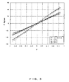
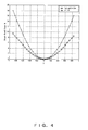
- Figs. 3 and 4 each is a diagram showing a comparison of the preferred embodiment (o:
- the vertical axis of Fig. 3 is a mono-pulse angle measurement value ⁇ (i.e., the range of the top to bottom of each characteristic line is an FOV), and ⁇ est shown in Fig. 4 is a calculated value by means of a mono-pulse angle measurement, and ⁇ ref is a physical angle (i.e., the conventional method: ref-c and the present invention: ref-n in the showing of Fig.
- the ⁇ at around 20° that is the FOV limit accomplished by the conventional method is about 0.6 for example, whereas the ⁇ in the case of measuring an angle at around 20° is about 0.4 according to the present invention, meaning that a relative error of the ⁇ when measuring the same angle of 20° is about 9% for the conventional method, whereas it is 2% for the embodiment of the present invention, thus an improvement of about 1/5 reduction.
- the conventional method is a mono-pulse angle measurement using two sets of antenna
- the only way to extend the FOV is to narrow the absolute interval between the individual antennas, while is faced with a difficulty in avoiding a degradation of angle measurement accuracy nearby the end of the FOV.
- narrowing the absolute interval between the antennas is faced with serious problems in consideration of the physical size limit, electromagnetic coupling and gain, and an improvement of angle measurement accuracy by just averaging can never provide a fundamental solution.
- the preferred embodiment of the present invention has no problem with the absolute interval between antennas and therefore enables a setup for a highly flexible performance (e.g., an FOV can remain wide even if the absolute interval between antennas becomes large as a result of obtaining a large gain by designing large individual antennas). It is also easy to improve the angle measurement accuracy as shown in Fig. 4.
- the present embodiment can be implemented by a program or circuit.
- an inverse trigonometric function is usually incorporated as a scheme of a Taylor expansion (refer to the second term of left-hand side of the expression 2.2.1); it may, however, be substituted by a Pade expansion (refer to the third term of the left-hand side of the aforementioned expression).
- the Pade expansion is well known to provide a numerical stability and high accuracy than the Taylor expansion (e.g., set for M ⁇ N+1 or such), possibly providing a compensation effect in a calculation in the case in which a normal calculation could result in an error by exceeding a domain of a trigonometric function due to an influence of a noise or such.
- Figs. 5 and 6 each is a diagram describing the case of applying the preferred embodiment of the present invention to a regular-interval array sensor.
- an angle formed by a straight line passing z, z* and "0" in terms of a method of least squares and a real or imaginary axis is regarded as 2 ⁇ asin ⁇ .
- z and z* which are obtained by an n-time of measurements, on a unit circle, two circles defined by
- Fig. 6 is a process flow in the case of a regular interval array.
- the error limit ⁇ is calculated by min (S/N), the minimum value of S/N ratio, or such for example.
- the step S11 measures a signal and the step S12 judges whether or not the absolute value of the difference between the absolute value of arg (Zn) and that of arg (Zn*) is less than or equal to the ⁇ . If the judgment of the step S12 is "yes", an incoming angle is determined to be an sin -1 ((1/2na)arg(Zn)).
- step S12 If the judgment of the step S12 is "no", the step S14 stores the arg (Zn) and arg(Zn*), and the step S15 judges whether the number of measurement times n is equal to or more than a specified number of times, e.g., "3". If the judgment of the step S15 is "no", the process returns to the step S11 for measuring a signal.
- step S15 calculates the centers z 0 and z 0 * of a circle passing the Zn and Zn* by applying a method of least squares
- step S17 calculates a straight line L passing the z 0 , z 0 * and "0" by applying a method of least squares
- step S18 determines the incoming angle to be sin -1 ((1/2 ⁇ a)arg(L)).
- the expression 2.7.1 is obtained by changing a phase reference and an angle ⁇ is calculated by using the expression 2.7.2.
- the same trigonometric function that requires a relatively large load among the elementary function can be used satisfactorily and therefore a program size can be a little smaller.
- Such a configuration determines an FOV by a relative interval between sensors, instead of an absolute interval therebetween, thereby making it possible to secure an extremely wide FOV which used to be very difficult by employing the conventional mono-pulse apparatus.
- Fig. 7 is a block configuration diagram of a mono-pulse radar incorporating an incoming direction estimation apparatus according to the preferred embodiment of the present invention.
- a radar wave received by these antennas is converted into a baseband signal by an RF receiver 10.
- the baseband signal is converted into a digital signal by a BB circuit and an analog-to-digital (A/D) converter 11, and also subjected to processing as a baseband signal.
- a distance/speed estimator 12 estimates a distance to a target and a speed thereof by using the processed baseband signal, and the incoming direction estimation apparatus 13 according to the present embodiment estimates an incoming direction of the radar wave from the target.
- the incoming direction of the radar wave is used as a direction of the target.
Landscapes
- Engineering & Computer Science (AREA)
- Radar, Positioning & Navigation (AREA)
- Remote Sensing (AREA)
- Computer Networks & Wireless Communication (AREA)
- Physics & Mathematics (AREA)
- General Physics & Mathematics (AREA)
- Radar Systems Or Details Thereof (AREA)
Abstract
Description
- The present invention relates to an incoming direction estimation apparatus.
- Fig. 1 is a diagram showing a mono-pulse radar as an example of a conventional incoming direction estimation apparatus.
- This apparatus is a system comprising one transmission antenna AT, two reception antennas AR0 and AR1, an interface module (this comprisal adopts a single-pole, double-throw (SPDT)), which interfaces the reception antennas, and a radio frequency (RF) unit, an RF unit constituted by a transceiver and receiver, an RF oscillator, a base band (BB) oscillator, a BB module (not shown herein) comprising an analog to digital (A/D) converter, et cetera, and a signal processing apparatus (also not shown herein) comprising a central processing unit (CPU) and such. A radar wave transmitted from the antenna AT is received by the antennas AR0 and AR1 after being reflected on an angle measurement target. The radar wave transmitted from the antenna AT uses an RF signal that is a resultant of an oscillation frequency of the RF oscillator RF-VCO being modified by a signal of a triangular wave oscillated and emitted by the base band oscillator BB-OSC, or the like wave, followed by being amplified by a high power amplifier (HPA). The radar wave received by the antennas AR0 and AR1 is led by way of the switch SPDT, amplified by the low noise amplifier (LNA), mixed with the transmission radar wave by the multiplier M and converted into a base band signal BB. Thus obtained base band signal BB is processed by the BB module and CPU that are placed in the later stage, and an incoming direction of the radar wave (named simply as "radar wave" hereinafter) reflected on the angle measurement target is estimated.
- Assuming that the angle measurement target is positioned at an angle θ relative to the normal line direction of the antenna surface (angle measurements are made clockwise with illustrated normal line as 0 degrees), a signal x (t) incoming from the target at a clock time t is received by the antennas AR0 and AR1, and down-converted, thereby becoming a base band signals y0 (t) and y1(t) as the following expressions:


where n0(t) and n1(t) are noise components and t is omitted for simplicity of an expression; and α is d/λ assuming that the antenna interval is d, the wavelength of an un-modulated output signal (named as "carrier signal" hereinafter) from the RF-VCO is λ, and j is an imaginary unit. In this case, the simplest method for calculating the θ among conceivable methods is defining
followed by calculating a ratio of Δy to Σy to obtain:
and therefore the θ can be calculated by using the following expression provided that Δε and Σε are sufficiently small.
where the following is defined:

- Note that Im takes an imaginary number part of an argument in the above expression. Now, let it be assumed that γ is expressed by γ= -Im(Δy/Σy), then it is necessary to set it at α= 1/2 in order to be able to use the entirety of a domain of sin-1 (where sin-1 (x) ; |x| ≤ 1) if tan-1 (γ) changes when trying to obtain a maximum field of view (FOV) (i.e., a field angle of a radar) because the value range of the tan-1 (γ) determining the domain of definition of sin-1 is |tan-1(γ)| ≤ n/2. It is, however, difficult to set the α at such a value because of a consideration of a system gain and an electromagnetic coupling between the antennas, and therefore the α is usually set at about 1 to 2. That is, α= d/λ where the antenna interval is d and a wavelength of the carrier signal is λ, and therefore the antennas must be placed in an extremely small interval in the unit of millimeter in order to accomplish a value such as α= 1/2 by a short wave signal especially a radar or such. Too small an antenna interval, however, generates an electromagnetic coupling between the two antennas, losing an independence of two reception signals that are supposed to be obtained by essentially maintaining an exact phase difference indicated by the above expressions 1.1 and 1.2, and therefore an approximation represented by the expression 1.5 is no longer applicable even if Δy/Σy is forcibly transformed, resulting in making it difficult to estimate the θ accurately. Meanwhile, a try to obtain a sufficient system gain needs to take a sufficient gain of the antennas, generally requiring a large area size for each antenna. Consequently, a try to obtain a sufficient system gain makes the antennas become large, creating a situation of making it impossible to minimize the antenna interval.
- Accordingly, one considers a way of obtaining a maximum FOV based on such an α (e.g., FOV ≈ ±23° in the case of α = 1.25), in which case, however, an angle must be measured by using the entire value zone of tan-1(γ). The tan-1(γ), however, is a nonlinear function in which a derivative becomes smaller than "1" with a distance from the original point, and the nonlinearity of the tan-1(γ) further influences the sin-1 that is also a nonlinear function adversely to a large γ (i.e., to a signal incoming from an angle close to an FOV limit), thus resulting in fundamentally degrading accuracy of a measurement angle.
- Incidentally, there is a known technique (per
reference patent documents 1 and 2) of configuring an array by placing three element antennas in irregular intervals, carrying out a conventional mono-pulse angle measurement by using two sets of antennas, and applying an averaging operation and such, in order to reduce an error nearby the FOV. Except that the error reduction method of the known technique is an extension of the conventional mono-pulse method using two signals after all. - In summary, the conventional incoming direction estimation apparatus has been faced with the following problems:
- 1. A mono-pulse apparatus employing two reception-use sensors are commonly used for an apparatus estimating a direction of arrival (DOA) of a single signal by using a signal sensor comprising a sensor array. The apparatus, however, has a limited field of view (FOV) constrained by an absolute interval between the sensors and, moreover, a direction estimation error increases toward the edges of the FOV in terms of the primary value of an inverse triangular function. Meanwhile, a try to increase the FOV is limited by a difficulty of setting individual sensors less than a certain interval due to the problem of physical size, gain or electromagnetic coupling of the individual sensors.
- 2. There is a known technique (per
reference patent documents 1 and 2) as a proposal for correcting a DOA error nearby the FOV among the problems noted in theabove paragraph 1. These apparatuses place three or more antennas in irregular intervals, configures two sets of common mono-pulse apparatuses by selecting two antennas among the three or more antennas, applies to averaging or such to two DOAs θ0 and θ1 that are obtained from each mono-pulse apparatus and judges that a correct DOA is obtained only if the both of them are identical. In this method, however, the FOV per se is still controlled by the absolute interval between the antennas, thus failing to provide a fundamental solution to the problem of theabove paragraph 1. Another problem is that an essential degradation of an accuracy of measurement angle cannot be avoided because it is basically a simple combination of two sets of conventional mono-pulse apparatuses. - The object for the present invention is to provide an incoming direction estimation apparatus capable of obtaining a wide field of view (FOV) and providing a high accuracy of angle measurement.
- An incoming direction estimation apparatus according to the present invention comprises: at least three sensors for receiving a signal from a target by being placed so as to make |a1-a0| equal to or less than 1/4 when defining a distance between first sensors as do = a0*λ and a distance between second sensors as d1 = a1*λ, where the a0 and a1 are set as constant and the λ is defined as wavelength of a carrier, or such, carrying a reception signal; and an estimation unit for estimating an incoming direction of the signal by using the at least three sensors simultaneously.
- The present invention is contrived to reduce an apparent value range of tan-1(γ) included in an arithmetic expression used for estimating a direction by using signals from three (or more) sensors simultaneously and bring a necessary field of view into a zone where a calculation error is fundamentally small. This in turn makes it possible to widen an FOV per se.
-
- Fig. 1 is a diagram showing a mono-pulse radar as an example of a conventional incoming direction estimation apparatus;
- Fig. 2 is a diagram of an outline comprisal of a mono-pulse radar incoming direction estimation apparatus according to a preferred embodiment of the present invention;
- Fig. 3 is a diagram showing a comparison of the preferred embodiment (O: |a1-a0|= 1/2Π) of the present invention with a conventional system (x: a= 1/4) (part 1);
- Fig. 4 is a diagram showing a comparison of the preferred embodiment (o: |a1-a0|= 1/2Π) of the present invention with a conventional system (x: a= 1/4) (part 2);
- Fig. 5 is a diagram describing the case of applying the preferred embodiment of the present invention to a regular-interval array sensor (part 1);
- Fig. 6 is a diagram describing the case of applying the preferred embodiment of the present invention to a regular-interval array sensor (part 2); and
- Fig. 7 is a block configuration diagram of a mono-pulse radar incorporating an incoming direction estimation apparatus according to the preferred embodiment of the present invention.
- While the present invention is applicable to other incoming direction estimation apparatuses such as a sonar in lieu of a mono-pulse radar described above, a description herein exemplifies a mono-pulse radar in terms of a comparison of the conventional technique, and exemplifies the case of N= 3, where N is the number of sensors.
- Fig. 2 is a diagram of an outline comprisal of a mono-pulse radar incoming direction estimation apparatus according to a preferred embodiment of the present invention.
- In the showing of Fig. 2, the same component sign is assigned to the same constituent component as one shown in Fig. 1 and the description thereof is omitted here.
- The configuration shown by Fig. 2 is equipped with three reception antennas. A switch SP3T (single-pole, 3-throw) changes over radar wave reception signals from the three antennas sequentially and transmits them to a later stage.
- Where defining antenna intervals of three antennas (A0, A1 and A2) as: d0= a0λ between the A0 and A1, and d1= a1λ between the A1 and A2, a baseband component of a signal received at each antenna is given by the following expression (See Fig. 1, expressions 1.1 and 1.2.) :


- Then, calculations of


obtains
- Therefore, if an S/N ratio is sufficiently large, the following is
possible 
and accordingly proceeding to calculate an angle of a target by the following expression 2.1.8, and: -- - (1) First, defining as |a1-a0| ≥ 1/4 makes it possible to expand only an FOV without excluding an angle measurement by using all value zone of tan-1(γ) as in the case of the conventional technique when calculating arg(y2y0/y1 2) substituted by γ= Im(y2y0/y1 2) /Re (y2y0/y1 2) and by using arg(γ)=tan-1(γ). Note that it means the Im takes an imaginary part of an argumant and the Re takes a real part of the argumant. The arg represents an angle on a complex plane.
- (2) Moreover, the domain of sin-1(x) is |x|≤ 1, and therefore it is possible to improve angle measurement accuracy while securing a larger FOV than the conventional method by limiting to a zone where a relationship of γ-tan-1(γ) is relatively highly linear, e.g., excluding a zone outside the good-linearity-domain of sin-1(x) by setting, for example, |a1-a0|≤ 1/4, i.e., |a1-a0| = 1/2π for example, or multiplying tan -1(γ) by a scaling.
- That is, a degradation of angle estimation accuracy caused by a problem of a principal value of a trigonometric function can be compensated and also an FOV can be expanded. Nor is there a necessity of correcting by obtaining a difference between DOAs by using an individual set of antennas.
- Figs. 3 and 4 each is a diagram showing a comparison of the preferred embodiment (o: |a1-a0| = 1/2Π) of the present invention with a conventional system (x: a= 1/4).
- The horizontal axis of Figs. 3 and 4 shows γ= -Im (Δy/Σy) for the conventional method and γ= Im(y2y0/y1 2) /Re (y2y0/y1 2) for the preferred embodiment of the present invention. The vertical axis of Fig. 3 is a mono-pulse angle measurement value θ (i.e., the range of the top to bottom of each characteristic line is an FOV), and θest shown in Fig. 4 is a calculated value by means of a mono-pulse angle measurement, and θref is a physical angle (i.e., the conventional method: ref-c and the present invention: ref-n in the showing of Fig. 3) of an angle measurement target in each method. Comparing the method of the embodiment of the present invention with the conventional method shown in Fig. 3, the method of the embodiment of the present invention apparently achieves a wider FOV (this example shows a measurement angle range of about two times of the conventional method) for a value of each γ, also obtaining the angle close to the actual angle (i.e., the physical angle). Meanwhile, Fig. 4 shows that a value of error for a value of each γ increases with the absolute value of γ for both of the methods. Describing another benefit of the present invention by referring to Fig. 3 and Fig. 4, the γ at around 20° that is the FOV limit accomplished by the conventional method is about 0.6 for example, whereas the γ in the case of measuring an angle at around 20° is about 0.4 according to the present invention, meaning that a relative error of the θ when measuring the same angle of 20° is about 9% for the conventional method, whereas it is 2% for the embodiment of the present invention, thus an improvement of about 1/5 reduction.
- Since the conventional method is a mono-pulse angle measurement using two sets of antenna, the only way to extend the FOV is to narrow the absolute interval between the individual antennas, while is faced with a difficulty in avoiding a degradation of angle measurement accuracy nearby the end of the FOV. As for the FOV, furthermore, narrowing the absolute interval between the antennas is faced with serious problems in consideration of the physical size limit, electromagnetic coupling and gain, and an improvement of angle measurement accuracy by just averaging can never provide a fundamental solution. Contrarily, the preferred embodiment of the present invention has no problem with the absolute interval between antennas and therefore enables a setup for a highly flexible performance (e.g., an FOV can remain wide even if the absolute interval between antennas becomes large as a result of obtaining a large gain by designing large individual antennas). It is also easy to improve the angle measurement accuracy as shown in Fig. 4.
- The present embodiment can be implemented by a program or circuit. In the case of implementing by a program, an inverse trigonometric function is usually incorporated as a scheme of a Taylor expansion (refer to the second term of left-hand side of the expression 2.2.1); it may, however, be substituted by a Pade expansion (refer to the third term of the left-hand side of the aforementioned expression). The Pade expansion is well known to provide a numerical stability and high accuracy than the Taylor expansion (e.g., set for M ≤ N+1 or such), possibly providing a compensation effect in a calculation in the case in which a normal calculation could result in an error by exceeding a domain of a trigonometric function due to an influence of a noise or such. Note that a Pade approximation (expansion) can be implemented by a filter and therefore a hardware configuration makes it possible to reduce a calculation load.

- While the argument of sin-1 excluding coefficients of the expression 2.1.8 is

however, paying attention to the fact that
calculating the θ by using a correction coefficients {βi} determined by a method of least squares or such to define such as:
makes it possible to further improve accuracy of an angle estimation because it is possible to give a correction only to the numerator. Incidentally, the range of integer i may be arbitrarily determined in consideration of accuracy, calculation load, et cetera. - Figs. 5 and 6 each is a diagram describing the case of applying the preferred embodiment of the present invention to a regular-interval array sensor.
- In the case of a regular-interval array sensor, when S/N ratio is sufficiently large, the expression is
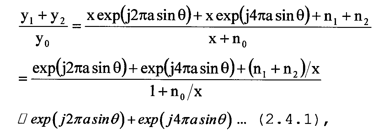
substituting z= exp(j2Πasinθ) and (y2+y1)/y0= b makes solutions z and z* (* means taking a complex conjugate) of a quadratic equation z2+z-b=0 appear at the position of a conjugate symmetry on a Gauss plane. Accordingly, if the θs given by the following expression become identical while ignoring a sign, it is regarded as an appropriate value:
- If both of them are not identical due to an influence of a calculation error and such, an angle formed by a straight line passing z, z* and "0" in terms of a method of least squares and a real or imaginary axis is regarded as 2πasinθ. Or, plotting z and z*, which are obtained by an n-time of measurements, on a unit circle, two circles defined by |zn-z0|≤ ε and |zn*-z0*|≤ ε' are obtained related to certain deviations (ε, ε') and true solutions (z0, z0*) as shown in Fig. 5. It is followed by calculating the center of them (z0, z0*) by using a method of least squares or such, and an angle formed by a straight line, which passes these points and "0" in terms of a method of least squares, and a real axis or imaginary axis is regarded as 2Πasinθ.
- Fig. 6 is a process flow in the case of a regular interval array.
- The step S10 sets an error limit σ and the number of measurement times n= 0. The error limit σ is calculated by min (S/N), the minimum value of S/N ratio, or such for example. The step S11 measures a signal and the step S12 judges whether or not the absolute value of the difference between the absolute value of arg (Zn) and that of arg (Zn*) is less than or equal to the σ. If the judgment of the step S12 is "yes", an incoming angle is determined to be an sin-1((1/2na)arg(Zn)). If the judgment of the step S12 is "no", the step S14 stores the arg (Zn) and arg(Zn*), and the step S15 judges whether the number of measurement times n is equal to or more than a specified number of times, e.g., "3". If the judgment of the step S15 is "no", the process returns to the step S11 for measuring a signal. If the judgment of the step S15 is "yes", then the step S16 calculates the centers z0 and z0* of a circle passing the Zn and Zn* by applying a method of least squares, the step S17 calculates a straight line L passing the z0, z0* and "0" by applying a method of least squares, and the step S18 determines the incoming angle to be sin-1((1/2Πa)arg(L)).
- In the case of a regular interval array, the expression 2.7.1 is obtained by changing a phase reference and an angle θ is calculated by using the expression 2.7.2. The same trigonometric function that requires a relatively large load among the elementary function can be used satisfactorily and therefore a program size can be a little smaller.


- By configuring a sensor array (where |ai-aj|≥1/4, or |ai-aj|≤1/4 for ∀i and j (where j≠i); either may be determined in consideration of a balance between an expansion of FOV and angle measurement accuracy) by lining up an N-piece of sensors (where N ≥ 3) receiving a signal in an interval of d0= a0λ through dN-2= a N-2λ, where the wavelength of a carrier signal is λ, and setting three signals as one set (which is indicated by i, j, k) of all signals y1 through yN-1 that have been received by the individual sensors, a θ of the DOA is calculated by the following expression:

- Such a configuration determines an FOV by a relative interval between sensors, instead of an absolute interval therebetween, thereby making it possible to secure an extremely wide FOV which used to be very difficult by employing the conventional mono-pulse apparatus.
- Meanwhile, setting |aj-ai|= 1/2Π for example makes it possible to measure an angle in a zone where the arg( ) and sin-1( ), which are nonlinear functions, indicate a good linearity, by measuring angle by using a part of a value zone of arg(ykyi/yj 2), thereby enabling a fundamental reduction of an angle measurement error nearby the end of the FOV. Meanwhile, it is a relative interval between sensors that determines an FOV, and therefore it is also easy to make a high gain apparatus by enlarging an individual sensor area size of such without changing an FOV.
- Fig. 7 is a block configuration diagram of a mono-pulse radar incorporating an incoming direction estimation apparatus according to the preferred embodiment of the present invention.
- The assumption is that N pieces of antennas (i.e., A0 through AN-1) are equipped, in lieu of limiting to three antennas. A radar wave received by these antennas is converted into a baseband signal by an
RF receiver 10. The baseband signal is converted into a digital signal by a BB circuit and an analog-to-digital (A/D)converter 11, and also subjected to processing as a baseband signal. Then a distance/speed estimator 12 estimates a distance to a target and a speed thereof by using the processed baseband signal, and the incomingdirection estimation apparatus 13 according to the present embodiment estimates an incoming direction of the radar wave from the target. The incoming direction of the radar wave is used as a direction of the target. Once the estimation value of the distance, speed and incoming direction is obtained, it is output to a display or such for presenting to a user or such.
Patent document 2: Laid-Open

Claims (13)
- An incoming direction estimation apparatus, comprising:
at least three sensors for receiving a signal from a target by being placed so as to make |a1-a0| equal to or less than 1/4 when setting a distance between first sensors as do = a0*λ and a distance between second sensors as d1 = a1*λ, where a0 and a1 are set as constant and λ is defined as wavelength of a carrier, or such, carrying a reception signal; and
an estimation means for estimating an incoming direction of the signal by using the at least three sensors simultaneously. - The incoming direction estimation apparatus according to claim 1, wherein
said estimation means estimates an incoming direction of a signal based on
where y0 is a signal received by first sensors, y1 is a signal received by second sensors and y2 is a signal received by third sensors. - The incoming direction estimation apparatus according to claim 1, wherein
said estimation means estimates an incoming direction of a signal based on
by using βi (where i is an integer) that is set for best estimating an actual incoming angle,
where using y0: a signal received by first sensors, y1: a signal received by second sensors and y2: a signal received by third sensors, γ is defined as
- The incoming direction estimation apparatus according to claim 3, wherein
said βi is determined based on a method of least squares so as to best estimate an actual incoming direction. - The incoming direction estimation apparatus according to claim 1, wherein
said estimation means estimates an incoming direction of a signal based on
by setting (y2+y1)/y0 = b and a= d/λ where y0 is a signal received by first sensors, y1 is a signal received by second sensors and y2 is a signal received by third sensors, and d1= d0= d. - The incoming direction estimation apparatus according to claim 5,
defining an angle:L formed between a straight line, which passes z= (-1+√(1+4b) /2, z*= (-1-√(1+4b))/2 and "0" in terms of a method of least squares, and a real axis or imaginary axis on a complex plane as 2Πasinθ, and an angle of an incoming direction is estimated based on:
if calculated angle of two incoming directions using z and z* are not identical. - The incoming direction estimation apparatus according to claim 6,
carrying out a plurality of measurements, calculating a center point of a distribution of values of said z and that of a distribution of said z* by using a method of least squares and defining an angle:L formed between a straight line on a complex plane, which passes the z, z* and "0" in terms of a method of least squares, and a real axis or imaginary axis as 2Πasinθ, and an incoming direction is estimated based on:
- The incoming direction estimation apparatus according to claim 1,
estimating an incoming direction of a signal based on
when defining a= d/λ where y0 is a signal received by first sensors, Y1 is a signal received by second sensors and y2 is a signal received by third sensors, and d1= d0= d. - The incoming direction estimation apparatus according to any one of claims 1 through 8, wherein
an arithmetic operation of said inverse trigonometric function is performed by using a Pade expansion. - The incoming direction estimation apparatus according to any one of claims 1 through 8, wherein
an arithmetic operation of said inverse trigonometric function is implemented by a filter incorporating an expression of inverse trigonometric function applied by a Pade expansion. - The incoming direction estimation apparatus according to claim 1,
setting as |a1-a0| = 1/2n. - The incoming direction estimation apparatus according to claim 1, wherein
the incoming direction estimation apparatus is applied to a mono-pulse radar. - An incoming direction estimation method, comprising:
equipping at least three sensors for receiving a signal from a target by being placed so as to make an |a1-a0| equal to or less than 1/4 when defining a distance between first sensors as do = a0*λ and a distance between second sensors as d1 = a1*λ, where the a0 and a1 are set as constant and the λ is defined as wavelength of a carrier, or such, carrying a reception signal; and
estimating an incoming direction of the signal by using the at least three sensors simultaneously.
Priority Applications (1)
| Application Number | Priority Date | Filing Date | Title |
|---|---|---|---|
| EP09166013A EP2113783B1 (en) | 2005-02-17 | 2005-02-17 | Incoming direction estimation apparatus |
Applications Claiming Priority (1)
| Application Number | Priority Date | Filing Date | Title |
|---|---|---|---|
| PCT/JP2005/002448 WO2006087783A1 (en) | 2005-02-17 | 2005-02-17 | Arriving direction estimator |
Related Child Applications (2)
| Application Number | Title | Priority Date | Filing Date |
|---|---|---|---|
| EP09166013A Division EP2113783B1 (en) | 2005-02-17 | 2005-02-17 | Incoming direction estimation apparatus |
| EP09166013.4 Division-Into | 2009-07-21 |
Publications (3)
| Publication Number | Publication Date |
|---|---|
| EP1850146A1 true EP1850146A1 (en) | 2007-10-31 |
| EP1850146A4 EP1850146A4 (en) | 2008-10-01 |
| EP1850146B1 EP1850146B1 (en) | 2010-08-04 |
Family
ID=36916199
Family Applications (2)
| Application Number | Title | Priority Date | Filing Date |
|---|---|---|---|
| EP09166013A Expired - Lifetime EP2113783B1 (en) | 2005-02-17 | 2005-02-17 | Incoming direction estimation apparatus |
| EP05719250A Expired - Lifetime EP1850146B1 (en) | 2005-02-17 | 2005-02-17 | Arriving direction estimator |
Family Applications Before (1)
| Application Number | Title | Priority Date | Filing Date |
|---|---|---|---|
| EP09166013A Expired - Lifetime EP2113783B1 (en) | 2005-02-17 | 2005-02-17 | Incoming direction estimation apparatus |
Country Status (5)
| Country | Link |
|---|---|
| US (1) | US7663549B2 (en) |
| EP (2) | EP2113783B1 (en) |
| JP (1) | JP4681599B2 (en) |
| DE (1) | DE602005022773D1 (en) |
| WO (1) | WO2006087783A1 (en) |
Cited By (1)
| Publication number | Priority date | Publication date | Assignee | Title |
|---|---|---|---|---|
| RU2367973C1 (en) * | 2008-03-26 | 2009-09-20 | Открытое Акционерное Общество "Научно-Исследовательский Институт Измерительных Приборов" /Оао "Нииип"/ | Method for radar surveillance of space (versions) |
Families Citing this family (11)
| Publication number | Priority date | Publication date | Assignee | Title |
|---|---|---|---|---|
| RU2450283C1 (en) * | 2011-02-08 | 2012-05-10 | Открытое акционерное общество "Авангард" | Direction finding phase method and phase direction finder for implementing said method |
| US8451164B2 (en) | 2011-02-09 | 2013-05-28 | Lawrence Livermore National Security, Llc. | Radar network communication through sensing of frequency hopping |
| RU2458355C1 (en) * | 2011-04-29 | 2012-08-10 | Открытое акционерное общество "Центральное конструкторское бюро автоматики" | Phase direction finder |
| US8849229B2 (en) | 2012-06-01 | 2014-09-30 | Wisconsin Alumni Research Foundation | Electrically small, super directive antennas |
| RU2526533C2 (en) * | 2012-12-03 | 2014-08-27 | Открытое акционерное общество "Омский научно-исследовательский институт приборостроения" (ОАО "ОНИИП") | Phase-based direction-finder |
| RU2532259C2 (en) * | 2013-01-09 | 2014-11-10 | Открытое акционерное общество "Омский научно-исследовательский институт приборостроения" (ОАО "ОНИИП") | Phase-based direction finding method |
| RU2536440C1 (en) * | 2013-05-29 | 2014-12-27 | Открытое акционерное общество "Центральное конструкторское бюро автоматики" | Phase-based direction-finder |
| RU2543065C1 (en) * | 2013-12-20 | 2015-02-27 | Открытое акционерное общество "Центральное конструкторское бюро автоматики" | Phase-based direction-finder |
| RU2599257C1 (en) * | 2015-11-30 | 2016-10-10 | Борис Николаевич Горевич | Method of radio signals spatial processing |
| CN113412433A (en) * | 2019-01-31 | 2021-09-17 | 三菱电机株式会社 | Angle measuring device, angle measuring method and vehicle-mounted device |
| CN113777555A (en) * | 2021-08-26 | 2021-12-10 | 南京航空航天大学 | DOA tracking method based on sparse array |
Family Cites Families (10)
| Publication number | Priority date | Publication date | Assignee | Title |
|---|---|---|---|---|
| US3633205A (en) * | 1969-06-30 | 1972-01-04 | Loral Electronics Corp | Wideband interferometer type antenna systems |
| US5600326A (en) * | 1991-12-16 | 1997-02-04 | Martin Marietta Corp. | Adaptive digital beamforming architecture and algorithm for nulling mainlobe and multiple sidelobe radar jammers while preserving monopulse ratio angle estimation accuracy |
| DE19543813A1 (en) * | 1995-11-24 | 1997-05-28 | Bosch Gmbh Robert | Radar system, in particular motor vehicle radar system |
| US5657027A (en) * | 1996-06-02 | 1997-08-12 | Hughes Electronics | Two dimensional interferometer array |
| JP2000230974A (en) | 1999-02-09 | 2000-08-22 | Toyota Motor Corp | Radar equipment |
| JP2001091616A (en) * | 1999-09-22 | 2001-04-06 | Mitsubishi Electric Corp | Incident angle estimating apparatus and element antenna array method of incident angle estimating apparatus |
| CN1280640C (en) | 2000-06-05 | 2006-10-18 | Tc许可有限公司 | Method and apparatus for determining the direction of a transponder in a modulated backscatter communication system |
| JP2004228615A (en) | 2003-01-17 | 2004-08-12 | Ntt Docomo Inc | Key isolation type encryption method using secret information unique to user, key isolation type encryption system, and external auxiliary device |
| EP2977783B1 (en) * | 2003-04-10 | 2020-06-24 | Leonardo Mw Ltd | Interferometers |
| JP4681664B2 (en) * | 2009-10-05 | 2011-05-11 | 富士通株式会社 | Direction of arrival estimation device |
-
2005
- 2005-02-17 WO PCT/JP2005/002448 patent/WO2006087783A1/en not_active Ceased
- 2005-02-17 JP JP2007503523A patent/JP4681599B2/en not_active Expired - Fee Related
- 2005-02-17 EP EP09166013A patent/EP2113783B1/en not_active Expired - Lifetime
- 2005-02-17 DE DE602005022773T patent/DE602005022773D1/en not_active Expired - Lifetime
- 2005-02-17 EP EP05719250A patent/EP1850146B1/en not_active Expired - Lifetime
-
2007
- 2007-08-17 US US11/889,903 patent/US7663549B2/en not_active Expired - Fee Related
Cited By (1)
| Publication number | Priority date | Publication date | Assignee | Title |
|---|---|---|---|---|
| RU2367973C1 (en) * | 2008-03-26 | 2009-09-20 | Открытое Акционерное Общество "Научно-Исследовательский Институт Измерительных Приборов" /Оао "Нииип"/ | Method for radar surveillance of space (versions) |
Also Published As
| Publication number | Publication date |
|---|---|
| EP1850146A4 (en) | 2008-10-01 |
| EP2113783A1 (en) | 2009-11-04 |
| US7663549B2 (en) | 2010-02-16 |
| EP2113783B1 (en) | 2011-09-28 |
| US20080007455A1 (en) | 2008-01-10 |
| JP4681599B2 (en) | 2011-05-11 |
| DE602005022773D1 (en) | 2010-09-16 |
| WO2006087783A1 (en) | 2006-08-24 |
| EP1850146B1 (en) | 2010-08-04 |
| JPWO2006087783A1 (en) | 2008-07-03 |
Similar Documents
| Publication | Publication Date | Title |
|---|---|---|
| US7663549B2 (en) | Incoming direction estimation apparatus | |
| US7825858B2 (en) | Methods and systems for frequency independent bearing detection | |
| JP4232570B2 (en) | Radar equipment for vehicles | |
| EP1760488B1 (en) | Radar apparatus | |
| JP4737165B2 (en) | Radar target detection method and radar apparatus using the target detection method | |
| US8049662B2 (en) | Systems and methods for antenna calibration | |
| US9234956B2 (en) | Radar device | |
| US9024812B2 (en) | Systems and methods for providing antenna calibration | |
| EP2386871B1 (en) | Radar apparatus | |
| US8884810B2 (en) | Compact beacon radar and full ATC services system | |
| EP2482097B1 (en) | Radar device and method of calculation of receive power in radar device | |
| KR20160134436A (en) | Method for estimating direction of arrival and apparatus for estimating direction of arrival using the same | |
| WO2008015883A1 (en) | Radar target detecting method, and radar device using the method | |
| JP3918573B2 (en) | Radar equipment | |
| JP2018116000A (en) | Radar device and object recognition method | |
| EP2096457B1 (en) | Digital beam forming using frequency-modulated signals | |
| JP2001201526A (en) | Antenna measuring device and antenna measuring method | |
| US20170016985A1 (en) | Positioning system | |
| KR101770097B1 (en) | Interferometry based angle estimation apparatus using direct phase difference comparison and method therefore | |
| JP7396128B2 (en) | Calibration device, calibration system, and calibration method for antenna device | |
| JP4681664B2 (en) | Direction of arrival estimation device | |
| EP3792642B1 (en) | Measuring antenna array beam synthesis method and apparatus | |
| JP2001201525A (en) | Antenna measuring device and antenna measuring method | |
| JP7164714B2 (en) | radar equipment | |
| US20240036183A1 (en) | Radar method and radar system for a phase-coherent analysis |
Legal Events
| Date | Code | Title | Description |
|---|---|---|---|
| PUAI | Public reference made under article 153(3) epc to a published international application that has entered the european phase |
Free format text: ORIGINAL CODE: 0009012 |
|
| 17P | Request for examination filed |
Effective date: 20070830 |
|
| AK | Designated contracting states |
Kind code of ref document: A1 Designated state(s): DE FR GB |
|
| DAX | Request for extension of the european patent (deleted) | ||
| RBV | Designated contracting states (corrected) |
Designated state(s): DE FR GB |
|
| A4 | Supplementary search report drawn up and despatched |
Effective date: 20080903 |
|
| 17Q | First examination report despatched |
Effective date: 20081119 |
|
| GRAP | Despatch of communication of intention to grant a patent |
Free format text: ORIGINAL CODE: EPIDOSNIGR1 |
|
| GRAS | Grant fee paid |
Free format text: ORIGINAL CODE: EPIDOSNIGR3 |
|
| GRAA | (expected) grant |
Free format text: ORIGINAL CODE: 0009210 |
|
| AK | Designated contracting states |
Kind code of ref document: B1 Designated state(s): DE FR GB |
|
| REG | Reference to a national code |
Ref country code: GB Ref legal event code: FG4D |
|
| REF | Corresponds to: |
Ref document number: 602005022773 Country of ref document: DE Date of ref document: 20100916 Kind code of ref document: P |
|
| PLBE | No opposition filed within time limit |
Free format text: ORIGINAL CODE: 0009261 |
|
| STAA | Information on the status of an ep patent application or granted ep patent |
Free format text: STATUS: NO OPPOSITION FILED WITHIN TIME LIMIT |
|
| 26N | No opposition filed |
Effective date: 20110506 |
|
| REG | Reference to a national code |
Ref country code: DE Ref legal event code: R097 Ref document number: 602005022773 Country of ref document: DE Effective date: 20110506 |
|
| REG | Reference to a national code |
Ref country code: FR Ref legal event code: PLFP Year of fee payment: 12 |
|
| PGFP | Annual fee paid to national office [announced via postgrant information from national office to epo] |
Ref country code: GB Payment date: 20160217 Year of fee payment: 12 Ref country code: FR Payment date: 20160108 Year of fee payment: 12 |
|
| GBPC | Gb: european patent ceased through non-payment of renewal fee |
Effective date: 20170217 |
|
| REG | Reference to a national code |
Ref country code: FR Ref legal event code: ST Effective date: 20171031 |
|
| PG25 | Lapsed in a contracting state [announced via postgrant information from national office to epo] |
Ref country code: FR Free format text: LAPSE BECAUSE OF NON-PAYMENT OF DUE FEES Effective date: 20170228 |
|
| PG25 | Lapsed in a contracting state [announced via postgrant information from national office to epo] |
Ref country code: GB Free format text: LAPSE BECAUSE OF NON-PAYMENT OF DUE FEES Effective date: 20170217 |
|
| PGFP | Annual fee paid to national office [announced via postgrant information from national office to epo] |
Ref country code: DE Payment date: 20200204 Year of fee payment: 16 |
|
| REG | Reference to a national code |
Ref country code: DE Ref legal event code: R119 Ref document number: 602005022773 Country of ref document: DE |
|
| PG25 | Lapsed in a contracting state [announced via postgrant information from national office to epo] |
Ref country code: DE Free format text: LAPSE BECAUSE OF NON-PAYMENT OF DUE FEES Effective date: 20210901 |