EP1850110A1 - Measuring device for gravimetric moisture determination - Google Patents
Measuring device for gravimetric moisture determination Download PDFInfo
- Publication number
- EP1850110A1 EP1850110A1 EP06113027A EP06113027A EP1850110A1 EP 1850110 A1 EP1850110 A1 EP 1850110A1 EP 06113027 A EP06113027 A EP 06113027A EP 06113027 A EP06113027 A EP 06113027A EP 1850110 A1 EP1850110 A1 EP 1850110A1
- Authority
- EP
- European Patent Office
- Prior art keywords
- sample
- test
- measuring device
- radiation source
- housing part
- Prior art date
- Legal status (The legal status is an assumption and is not a legal conclusion. Google has not performed a legal analysis and makes no representation as to the accuracy of the status listed.)
- Withdrawn
Links
Images


Classifications
-
- F—MECHANICAL ENGINEERING; LIGHTING; HEATING; WEAPONS; BLASTING
- F26—DRYING
- F26B—DRYING SOLID MATERIALS OR OBJECTS BY REMOVING LIQUID THEREFROM
- F26B25/00—Details of general application not covered by group F26B21/00 or F26B23/00
- F26B25/22—Controlling the drying process in dependence on liquid content of solid materials or objects
- F26B25/225—Controlling the drying process in dependence on liquid content of solid materials or objects by repeated or continuous weighing of the material or a sample thereof
-
- F—MECHANICAL ENGINEERING; LIGHTING; HEATING; WEAPONS; BLASTING
- F26—DRYING
- F26B—DRYING SOLID MATERIALS OR OBJECTS BY REMOVING LIQUID THEREFROM
- F26B3/00—Drying solid materials or objects by processes involving the application of heat
- F26B3/28—Drying solid materials or objects by processes involving the application of heat by radiation, e.g. from the sun
- F26B3/283—Drying solid materials or objects by processes involving the application of heat by radiation, e.g. from the sun in combination with convection
-
- F—MECHANICAL ENGINEERING; LIGHTING; HEATING; WEAPONS; BLASTING
- F26—DRYING
- F26B—DRYING SOLID MATERIALS OR OBJECTS BY REMOVING LIQUID THEREFROM
- F26B3/00—Drying solid materials or objects by processes involving the application of heat
- F26B3/32—Drying solid materials or objects by processes involving the application of heat by development of heat within the materials or objects to be dried, e.g. by fermentation or other microbiological action
- F26B3/34—Drying solid materials or objects by processes involving the application of heat by development of heat within the materials or objects to be dried, e.g. by fermentation or other microbiological action by using electrical effects
- F26B3/343—Drying solid materials or objects by processes involving the application of heat by development of heat within the materials or objects to be dried, e.g. by fermentation or other microbiological action by using electrical effects in combination with convection
-
- F—MECHANICAL ENGINEERING; LIGHTING; HEATING; WEAPONS; BLASTING
- F26—DRYING
- F26B—DRYING SOLID MATERIALS OR OBJECTS BY REMOVING LIQUID THEREFROM
- F26B9/00—Machines or apparatus for drying solid materials or objects at rest or with only local agitation; Domestic airing cupboards
- F26B9/003—Small self-contained devices, e.g. portable
-
- G—PHYSICS
- G01—MEASURING; TESTING
- G01N—INVESTIGATING OR ANALYSING MATERIALS BY DETERMINING THEIR CHEMICAL OR PHYSICAL PROPERTIES
- G01N5/00—Analysing materials by weighing, e.g. weighing small particles separated from a gas or liquid
- G01N5/04—Analysing materials by weighing, e.g. weighing small particles separated from a gas or liquid by removing a component, e.g. by evaporation, and weighing the remainder
- G01N5/045—Analysing materials by weighing, e.g. weighing small particles separated from a gas or liquid by removing a component, e.g. by evaporation, and weighing the remainder for determining moisture content
Definitions
- the present invention relates to a gravimetric moisture measuring device.
- the weight loss can also be measured during the drying process.
- the weight value thereof decreases, which follows a weight-time curve which asymptotically approaches the dry weight of the sample.
- the curve is determined for the respective sample by comparative experiments and can be expressed mathematically in an approximation formula.
- a suitably equipped gravimetric moisture measurement meter can calculate the moisture content of a sample based on the measured curve parameters and the drying time and display it on a display unit. By this method, the material to be dried no longer has to be completely dried out, it is sufficient to determine the coordinates of two detection points in the weight-time diagram.
- the weight of a sample changes essentially as a function of the temperature, the drying time and the test chamber conditions. Above all, the high demands on the test room restrict the available devices in the market in their accuracy.
- the test chamber is a space enclosed by the housing of the measuring instrument and openable for introduction or removal of a sample. Inside the test room, a sample holder and a means for heating the sample are also arranged. The sample holder is connected to a gravimetric measuring device.
- a thin layer of the sample is applied to a flat sample holder, for example a sample cup.
- the shell is arranged in the measuring device for gravimetric determination of moisture in its areal extent preferably horizontally and parallel to the areal extent of the means for heating the sample, in order to allow a uniform heating of the sample.
- a measuring device for gravimetric determination of moisture of said genus is known from European Patent EP 0 611 956 B1 known. With this device, the feeding of the weighing pan outside the measuring device is carried out for gravimetric moisture determination. To do this, the balance is moved out of the meter housing on a drawer-shaped drawer. As a radiation source, an annular halogen lamp is used, which is arranged in the operating state above the sample holder.
- microwave heating is that samples with inhomogeneous moisture distribution are also heated inhomogeneously.
- the volatile components escaping from the heated areas of the sample in particular moisture in the form of water vapor, may partially condense in the cold spots of the sample, so that first of all a distribution of the moisture within the sample takes place before it is expelled therefrom.
- the resulting timing errors limit the accuracy of an evaluation by the calculation method described above.
- all that remains is that as much moisture as possible has to be expelled.
- the less moisture in the sample is present the lower the heat development.
- Aids such as weighing vessels Of plastic, which could produce the heat of expulsion under the influence of microwaves, often have themselves a certain moisture content or an affinity for moisture, so that instead of a drying process, an exchange of moisture between the sample and the weighing vessel can take place. Local overheating may also occur on the plastic weighing vessels, whereby the plastic material may be decomposed and the mass loss of escaping volatile decomposition products or material sublimated by the weighing vessel may be erroneously measured as the weight loss of the sample.
- the object of the present invention is therefore to provide a test chamber with improved test conditions in the measuring device for gravimetric moisture determination mentioned at the outset, which permits a more precise determination of the moisture content of a sample.
- a weighing device is arranged in the housing of a measuring device for gravimetric determination of moisture, which has a load receiving area and a test receptacle connectable to this load receiving area. Furthermore, the measuring device has a test chamber inside the housing, wherein the test receptacle is arranged in the test position in the test space.
- a means arranged in the test chamber for heating a sample placed on the sample holder has a first radiation source and a second radiation source, the sample holder being arranged between the first radiation source and the second radiation source. Ideally, the first radiation source is arranged above the sample holder in relation to the load direction and the second radiation source is arranged below the sample holder.
- measuring position means that the elements arranged in the measuring device are in such a way that a measurement can be carried out. Concrete this means that the sample receiver is located between the first radiation source and the second radiation source.
- the test receptacle is arranged in the measuring position in its planar extent in a plane orthogonal to the load direction, wherein the first radiation source and the second radiation source are arranged in their planar extent parallel to the sample holder.
- the arrangement according to the invention has considerable advantages over the known prior art.
- By arranging two radiation sources below and above the sample holder a much better influenced heat distribution in the test chamber and in the sample can be achieved.
- the sample is more even and warm through for a shorter time.
- the intensity of the radiation from both radiation sources can be adapted to the sample and the test sample used.
- By choosing a suitable temperature profile over the layer thickness of the applied sample the expulsion of the moisture can be further accelerated without the sample is decomposed.
- the differences depend on the sample and the method of application. The influence on the measurement result due to the irregular distribution of the sample on the sample receiver decreases due to the better influenced heat distribution in the sample.
- test recording essentially the load receiver or the weighing pan of a gravimetric measuring device is referred to.
- the weighing device and the test chamber are arranged side by side in the housing of the measuring device.
- At least one, preferably the weighing device facing wall of the test chamber has at least one passage through which passes through a connecting member and connects the weighing device with the arranged in the test room sample receptacle.
- the emissions of the first radiation source and the emissions of the second radiation source are independently controllable and / or controllable.
- the measuring device has a control and / or regulating electronics in order to specify a wide variety of measuring sequences with definable temperature-time profiles and, if appropriate, also to evaluate the recorded measured values directly.
- the temperature in the test room is measured by suitable means, for example a temperature sensor arranged in the test room.
- a moisture sensor can additionally be arranged in the test room.
- a radiation source can be selected from a variety of ways.
- a heating plate, a heating foil, a radiant heater, a heating coil, various broadband light sources such as a halogen heat lamp or a quartz heat lamp, a monochromatic light source, a Peltier element or a microwave generator can be used to heat the sample.
- the first radiation source has a radiation system which is different from the second radiation source.
- the combination of a microwave generator with a hot plate may prove to be particularly advantageous.
- At least one of the radiation sources should be mechanically connected to the housing and / or electrically connected to a power source via at least one plug connection. This is advantageous for two reasons. First, the replacement of a radiation source is much easier to accomplish. Second, different types of radiation sources can be assembled into a set of modules so that the user of the instrument from that set can select the ideal combination of radiation sources for his upcoming experiments.
- the radiation source is ideally provided with openings for the passage of volatile substances and / or vapors.
- test receptacle For easy loading or removal of the sample from the test space, the test receptacle can be coupled to the load receiving area or decoupled from the load receiving area.
- the structure of the measuring device may have various configurations.
- the first radiation source and the second radiation source are mechanically connected to one another as a unit, this unit being supported by a movable housing part and being pivotable about a substantially vertical axis.
- the sample holder can be freely accessible in the swiveled state.
- the first radiation source is connected to a movable housing part of the housing, which is designed as a cover, and this cover is pivotably mounted on a fixed housing part of the housing about a substantially horizontal pivot axis.
- the second radiation source is fixedly connected to the stationary housing part, wherein in the unfolded state of the lid, the sample holder can be freely accessible.
- the first and the second radiation source are fixedly connected to the stationary housing part and the weighing device is linearly guided together with the sample holder on a movable housing part and formed extendable out of the housing.
- the sample holder can be freely accessible in the extended state.
- the first and the second radiation source are fixedly connected to the stationary housing part and the weighing device is mounted pivotably together with the sample receptacle about a substantially vertical axis.
- the Weighing device may be freely accessible when swung state, the sample holder.
- the weighing device is fixedly connected to the housing together with the sample holder and at least the first radiation source is arranged on a substantially horizontally movable movable housing part. In the measuring position, this radiation source is located above the sample holder. In the loading position, this radiation source no longer covers the sample holder, making it freely accessible.
- the first and the second radiation source can also be arranged in the movable housing part, so that in the charging position none of the radiation sources is located below or above the sample receptacle.
- a suction device is subsequently arranged in the test chamber, preferably above the first radiation source. This serves to remove the volatile substances and / or the vapors.
- the suction device generates a slight negative pressure in the test chamber, whereby a gaseous medium outside of the measuring device, for example, is sucked through openings in the walls of the test room.
- the gaseous medium is passed through the test chamber in a suitable manner, where it can take up the volatile substances exiting the sample and / or the vapors and is then removed from the test chamber via the suction device.
- the gaseous medium can also be passed through the test room with overpressure.
- the suction device is not limited to active systems, for example a discharge opening with a fan or a vacuum pump. If a gaseous medium is introduced into the test chamber from the outside under overpressure via a gas supply device, this gas supply device and the discharge opening for removing the gases from the test chamber also constitute a suction device.
- the weighing results of the weighing device can be strongly influenced by the emissions of the radiation sources.
- Thermal insulation becomes the wall the test chamber preferably formed double-walled at least between the test chamber and the weighing device in order to guide the gaseous medium, preferably air, sucked in from outside the measuring device in the double-walled wall.
- the gaseous medium can of course also be introduced by overpressure in the meter.
- a means for eliminating electrostatic charges of the sample for example an ionizer, can be arranged in the test chamber or in the double-walled wall in order to eliminate static charges in the test chamber.
- the gaseous medium is chemically stable and inert to the sample and the materials of the testing room.
- gaseous media may be, for example, shielding gases such as nitrogen and noble gases such as argon.
- gaseous medium can be used to counteract a reuptake of the substances by the sample.
- a reacting with the exiting vapor or gaseous substances gaseous medium can be used to counteract a reuptake of the substances by the sample.
- various halogens could be used.
- the gaseous medium has a predefined moisture content. As a result, the reproducibility of comparison measurements can be improved.
- the measuring device preferably has a calibration device which serves the demand-controlled or automatic calibration of the weighing device.
- the calibration device may have a calibration weight or multiple calibration weights.
- the center of gravity lies the one or more calibration weights during a calibration operation on or near a center of gravity axis of the sample receiver and / or the sample extending in the load direction.
- the conditioning of the test room before the actual measurement allows constant test room conditions to be obtained, which has a very positive effect on the reproducibility of the measurement results.
- the reproducibility of results is an important feature of a gravimetric moisture measurement instrument. Only then can the results be compared.
- the measurement results are compared with empirical values. On the basis of the measurement results and the comparison values, the pretreatment of the substances or the setting data of the processing machines is determined.
- test room was conditioned. During this conditioning phase, if appropriate, the buoyancy and flow error adjustment can also be carried out.
- the measuring device 10 has a housing 20, in which a test chamber 30 is arranged.
- the housing 20 is divided into a movable housing part 22 and a stationary housing part 21.
- a weighing device 40 is arranged on the substantially horizontally movable movable housing part 22.
- the movable housing part 22 is guided in the stationary housing 21 by means of rollers 42, wherein the guide is shown only schematically.
- commercial guides such as Doppelauszugsschienen and the like can be used.
- a load cell 43, a Kalibrierwhenetzlegemechanismus 44 and at least one electronic module 45 are arranged and interconnected by transmission means 51.
- the electronic module 45 contains at least one signal processing module, not shown in detail, optionally also a control and / or regulation module.
- the load cell 43 has at least one fixed area 46 and a load receiving area 47.
- load cells for example, equipped with strain gauges elastic deformation body, load cells that operate on the principle of electromagnetic force compensation, load cells with vibrating strings, capacitive weighing sensors and the like.
- the fixed portion 46 is fixedly connected to the movable housing part 22 and the load receiving portion 47, a connecting member 53 is arranged, which connects a sample holder 60 with the load receiving portion 47.
- a sample cup 61 with a sample 62 can be placed on the sample holder 60. If it allows the design of the sample holder 60, can Of course, the sample 62 can also be applied directly to the sample holder 60.
- a Kalibriertypicalauflage 48 is formed on the connecting member 53.
- a calibration weight 49 can be applied to this calibration weight support 48 by the user or by the control of the measuring apparatus 10 by means of the calibration weight application mechanism 44 in order to determine a correction value for the measurement signal as a function of the instantaneous operating state of the measuring apparatus 10. After determining the correction value, the calibration weight 49 is again decoupled from the calibration weight support 48 and pressed against a stop 50 by the calibration weight application mechanism 44 until the next calibration process.
- Corner load error refers to the deviation in the measured value of a weighing device which causes the same load in its eccentric arrangement with respect to its centric arrangement on the sample holder (60).
- the weighing device 40 is in the measuring position; that is, the sample holder 60 is located in the test chamber 30 with the attached sample cup 61.
- a first radiation source 31 is arranged substantially parallel to the areal extent of the sample receptacle 60 in order to achieve the most homogeneous possible heat distribution at least on the surface of the sample 62.
- a second radiation source 32 is arranged substantially parallel to the sample holder 60 in the test chamber 30, the radiation of which acts on the sample 62 from below.
- an arrangement of the radiation sources 31, 32 parallel to the surface of the sample holder 60 is not absolutely necessary.
- a first radiation source 31 and / or second radiation source 32 arranged at an angle to the sample receptacle 60 may also be advantageous. Due to the two-sided action of the radiation from below and from above, a more homogeneous heat distribution in the sample 62 is achieved. This occurs in the Sample 62, as compared to a single-sided sample 62, has locally lower temperature spikes that can cause the sample 62 to thermally decompose at these locations. If the sample 62, for example a plastic, has a relatively low melting point, the surface of the sample 62 may locally melt in the event of inhomogeneous heating and inhibit the escape of the moisture from the sample 62. This can lead to massive errors in the calculated result when using a calculation method in which time-dependent parameters are used.
- discharge openings 26 are arranged in the housing 20 at a suitable location, preferably above the first radiation source 31.
- further ventilation openings are to be provided at a suitable location, preferably below the second radiation source 32.
- the feed opening 25 simultaneously serves to ventilate the test chamber 30, so that, as shown in FIG. 1, additional ventilation openings can be dispensed with.
- the radiation sources 31, 32 are detachably mechanically connected to the housing 20 via plug connections 33 and are electrically connected to a voltage source 34.
- the radiation sources 31, 32 can be removed from the test chamber 30 for cleaning or repair without much effort.
- plug connections 33 the user of the measuring device 10 can combine different radiation sources 31, 32 which differ in their mode of operation. This allows the user to create test room conditions matched to sample 62.
- the voltage source 34 in FIG. 1 has a first control device 35 for influencing the emissions of the first radiation source 31 and a second control device 36 for influencing the emissions of the second radiation source 32.
- a schematically illustrated temperature sensor 37 detects the temperature of the sample 62 and supplies the information necessary for controlling the radiation sources 31, 32 to the first and second control / regulating devices 35, 36.
- the voltage source is also connected to the weighing device 40 or to the electronic module 45 at least one flexible connection 52 connected. Thereby can be controlled by the electronic module 45, the control / regulating devices 35, 36.
- FIG. 2 shows the measuring device 10 from FIG. 1 with the weighing device 40 extended.
- the weighing device 40 essentially comprises the movable housing part 22, the weighing cell 43, the connecting link 53, the test receptacle 60, the calibration mounting mechanism 44, the calibration weight 49, the stop 50, the electronic module 45 and the transmission means 51.
- the flexible connection 52 between the voltage source 34 and the electronic module 45 must be flexible, so that the weighing device 40 can be pulled out of the stationary housing part 21 by the application of a sample cup 61 and / or a sample to the sample holder 60 or the removal of the sample cup 61 and / or to facilitate the sample.
- the calibration weight 49 is placed on the calibration weight support 48, which means that a correction value is determined by the electronic module 45 of the weighing device 40.
- FIG. 3 shows a second embodiment of the measuring device 110 according to the invention, shown in section.
- a weighing device 140 arranged in the housing 120 has essentially the same elements which were listed above in the description of FIG. 1 with regard to the weighing device 40.
- the housing 120 is divided into a fixed housing part 121 and a movable housing part 122.
- the weighing device 140 is not arranged in a horizontally movable housing part, but in the stationary housing part 121.
- the weighing device 140 is largely enclosed by the stationary housing part 121. Only a test receptacle 160 connected to the weighing device 140 projects out of the stationary housing part 121 and into the region of the movable housing part 122 when the movable housing part 122 is in the measuring position.
- this annular designed sample holder 160 differently configured containers such as sample cups 162, crucibles and the like can hang more.
- the movable housing part 122 forms the outer shell of a unit, which is connected about a vertical pivot axis 139 pivotally connected to the stationary housing part 121.
- a test space 130 is formed in the interior of the movable housing part 122, wherein a first radiation source 131 is arranged in the upper region of the test chamber 130 and a second radiation source 132 is arranged in the lower region of the test chamber 130.
- the movable housing part 122 has a charging opening 125, which is formed so that the sample holder 160 with applied sample 162 does not touch the movable housing part 122 during pivoting of the unit.
- the test chamber 130 surrounds the test receptacle 160 in the measuring position, wherein the first radiation source 131 is arranged above the test receptacle 160 and the second radiation source 132 is arranged below the test receptacle 160.
- the first radiation source 131 is lattice-shaped by means of a plurality of openings 180, so that the vapors and / or volatile substances escaping from a sample 162 can be better removed from the surroundings of the sample 162 via these openings 180.
- a suction device 170 is embedded in the movable housing part 121. The latter generates a negative pressure in the test chamber 130, so that air which surrounds the measuring device 110 is sucked into the test chamber 130 via ventilation openings 123 of the movable housing part 121, for example.
- the sucked air is heated in the test chamber 130 by the radiation sources 131, 132, absorbs the moisture escaping from the sample 162 and leaves the test chamber 130 via the suction device 170.
- the flow rate of the aspirated, gaseous medium, the moisture expelled from the sample 162 can be controlled via the suction power of the suction device 170.
- the suction channel of the suction device 170 can additionally be equipped with a filter 171, for example a fabric insert, an adsorption filter and / or a condenser.
- the gaseous medium with the absorbed moisture can be introduced via a hose 173, which adjoins the suction device 170, for example into the ventilation device of a domestic installation.
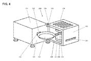
- FIG. 4 shows the three-dimensional representation of a measuring device 210 in the opened state.
- This third embodiment represents a variant of the measuring device 110 described in FIG. 3.
- the weighing device is arranged within a stationary housing part 221 and is covered by this housing part 221.
- the stationary housing part 221 has at least one wall 228 a passage 224 through which passes through a connecting member 253 of the weighing device.
- a test receptacle 260 is fixedly connected, which is formed in Figure 4 as a weighing pan and is shown without applied sample.
- a hinge 229 is formed, via which a movable housing part 222 is connected to the stationary housing part 221.
- the hinge 229 has a vertical pivot axis 239 arranged parallel to the load direction.
- the hinge 229 does not necessarily have to connect the housing parts 222, 221 to one another at the position illustrated; it can be arranged on the opposite, but also in the upper edge region of the wall 228, whereby in the arrangement in the upper edge region the pivot axis 239 has a horizontal orientation.
- the movable housing part 222 has a feed opening 225, which is closed by the wall 228 in the measuring position of the measuring device 210.
- the walls of the movable housing part 222 and the wall 228 of the fixed part form a test space 230, which is shown open in FIG. 4 and thus allows free access to the test receptacle 260.
- a first radiation source 231 and a second radiation source 232 are arranged such that in the measuring position, the first radiation source 231 above and the second radiation source 232 below the sample holder 260 are arranged.
- the movable housing part 222 has ventilation openings 223 in the side walls and exhaust openings 226 above the first radiation source 231.
- FIG. 5 shows a fourth embodiment of the measuring device 310 according to the invention, shown in section.
- a weighing device 340 arranged in the housing 320 has substantially the same elements as described above in the description of FIG. 1 with regard to the weighing device 40 were listed.
- the housing 320 is divided into a fixed housing part 321 and a movable housing part 322.
- the movable housing part 322 is designed as a cover, in which a first radiation source 331 is arranged.
- a suction device 370 is integrated in the movable housing part 322 above the first radiation source 331.
- This movable housing part 322 is connected via a hinge 329 in the upper region of the housing 320 with the stationary housing part 321, wherein the pivot axis of the hinge 329 is arranged substantially horizontally.
- the movable housing part 322 forms the upper part of a test room 330.
- the lower part of the test chamber 330 is formed in the stationary housing part 321. Arranged therein is a second radiation source 332.
- the link 353 mechanically connected to the weighing device 340 also protrudes into the lower part of the inspection space 330, so that a test receptacle 360 connected to the connecting link 353 is arranged above the second radiation source 332.
- a wall 328 of the fixed housing 321 between the weighing device 340 and the test chamber 330 is at least partially double-walled. As shown in FIG. 5, the double-walled embodiment forms a ventilation channel 327, through which a gaseous medium can be conducted into the test chamber 330. The medium flowing through during the measuring process thereby cools the wall 328, so that the heat radiating from the test chamber 330 can not penetrate into the housing region of the weighing device 340.
- the gaseous medium can be ionized in order to eliminate electrostatic charges of the sample.
- the wall 328 has a passage 324. This can be designed to be continuously closed, so that no medium flowing through the ventilation channel 327 passes through the passage 324 in the test room 330.
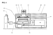
- FIG. 6 shows a fifth embodiment variant, shown in section, of the measuring device 410 according to the invention.
- the fixed housing part 421 and the elements arranged therein, such as a weighing device 440, a test receptacle 460, a connecting element 453 and a second radiation source 432 essentially correspond to the elements which were described above in the US Pat Description of Figure 5 were listed.
- the movable housing part 422 is not connected as in Figure 5 via a hinge with the stationary housing part 421, but is guided by means of guide rollers 418 and guide rails 419 in the stationary housing part 421 linearly displaceable.
- the test chamber 430 has a connection 415, which is connected via a flexible hose 416 to a pressure vessel 417 or a domestic installation.
- a gaseous medium is stored, which is preferably prepared by means of a treatment device 414, when flowing into the test chamber 330 has a defined, constant moisture content. Since the gaseous medium flows under pressure into the test chamber 430, the suction device 470 can also be replaced by exhaust ports.
- the presented embodiments show measuring devices for gravimetric moisture determination with different properties and features.
- the various properties and features have been presented for better clarity in various embodiments, wherein it is also possible to implement individual, several or all shown features and properties in a meter.
Abstract
Description
Die vorliegende Erfindung bezieht sich auf ein Messgerät zur gravimetrischen Feuchtigkeitsbestimmung.The present invention relates to a gravimetric moisture measuring device.
Zur Bestimmung des Feuchtigkeitsgehaltes einer Probe wird diese getrocknet und das Gewicht vor und nach dem Trocknungsvorgang manuell bestimmt. Durch die umfangreichen Arbeitsabläufe, die mit dieser Methode verbunden sind, ist diese sehr teuer und anfällig für Fehler.To determine the moisture content of a sample, it is dried and the weight is determined manually before and after the drying process. The extensive workflow associated with this method makes it very expensive and prone to errors.
Gegebenenfalls kann der Gewichtsverlust auch während des Trocknungsvorganges gemessen werden. Dabei nimmt bei einer bekannten Probe in Abhängigkeit der Temperatur, der Trocknungszeit und den Prüfraumbedingungen deren Gewichtswert ab, welcher einer Gewicht- Zeit- Kurve folgt, die sich asymptotisch dem Trockengewicht der Probe annähert. Die Kurve wird für die jeweilige Probe durch Vergleichsversuche ermittelt und kann in einer Näherungsformel mathematisch ausgedrückt werden. Aufgrund der zur Verfügung stehenden elektronischen Mittel kann ein entsprechend ausgerüstetes Messgerät zur gravimetrischen Feuchtigkeitsbestimmung den Feuchtigkeitsgehalt einer Probe anhand der gemessen Kurvenparameter und der Trocknungszeit errechnen und auf einer Anzeigeeinheit anzeigen. Durch diese Methode muss das zu trocknende Gut nicht mehr vollständig durchgetrocknet sein, es genügt die Ermittlung der Koordinaten zweier Erfassungspunkte im Gewicht-Zeitdiagramm.Optionally, the weight loss can also be measured during the drying process. In the case of a known sample, as a function of the temperature, the drying time and the test space conditions, the weight value thereof decreases, which follows a weight-time curve which asymptotically approaches the dry weight of the sample. The curve is determined for the respective sample by comparative experiments and can be expressed mathematically in an approximation formula. Because of the electronic means available, a suitably equipped gravimetric moisture measurement meter can calculate the moisture content of a sample based on the measured curve parameters and the drying time and display it on a display unit. By this method, the material to be dried no longer has to be completely dried out, it is sufficient to determine the coordinates of two detection points in the weight-time diagram.
Wie bereits eingangs erwähnt, verändert sich das Gewicht einer Probe im Wesentlichen in Abhängigkeit von der Temperatur, der Trocknungszeit und den Prüfraumbedingungen. Vor allem die hohen Anforderungen an den Prüfraum beschränken die auf dem Markt erhältlichen Geräte in ihrer Genauigkeit.As already mentioned, the weight of a sample changes essentially as a function of the temperature, the drying time and the test chamber conditions. Above all, the high demands on the test room restrict the available devices in the market in their accuracy.
Als Prüfraum wird ein durch das Gehäuse des Messgerätes umschlossener, zwecks Einführung beziehungsweise Entfernung einer Probe öffnenbarer Raum bezeichnet. Im Inneren des Prüfraums sind zudem eine Probeaufnahme und ein Mittel zur Erwärmung der Probe angeordnet. Die Probeaufnahme ist mit einem gravimetrischen Messgerät verbunden.The test chamber is a space enclosed by the housing of the measuring instrument and openable for introduction or removal of a sample. Inside the test room, a sample holder and a means for heating the sample are also arranged. The sample holder is connected to a gravimetric measuring device.
Üblicherweise wird eine dünne Schicht der Probe auf eine ebene Probeaufnahme, beispielsweise eine Probeschale aufgebracht. Die Schale wird im Messgerät zur gravimetrischen Feuchtigkeitsbestimmung in ihrer flächigen Ausdehnung vorzugsweise horizontal und parallel zur flächigen Ausdehnung des Mittels zur Erwärmung der Probe angeordnet, um eine gleichmässige Erwärmung der Probe zu ermöglichen.Usually, a thin layer of the sample is applied to a flat sample holder, for example a sample cup. The shell is arranged in the measuring device for gravimetric determination of moisture in its areal extent preferably horizontally and parallel to the areal extent of the means for heating the sample, in order to allow a uniform heating of the sample.
Als Mittel zur Erwärmung der Probe werden verschiedene Strahlungsquellen wie Heizstrahler, Mikrowellengeneratoren, Halogen- und Quarzlampen verwendet. Durch Versuche konnte festgestellt werden, dass eine der Hauptursachen einer ungenauen Messwerterfassung bei bestehenden Messgeräten zur gravimetrischen Feuchtigkeitsbestimmung die Art der verwendeten Strahlungsquellen und deren Anordnung im Prüfraum ist.As means for heating the sample, various radiation sources such as radiant heaters, microwave generators, halogen and quartz lamps are used. Experiments have shown that one of the main causes of inaccurate readings on existing gravimetric moisture analyzers is the type of radiation sources used and their arrangement in the test room.
Ein Messgerät zur gravimetrischen Feuchtigkeitsbestimmung der genannten Gattung ist aus der
Eine der Möglichkeiten, eine thermische Zersetzung der Probe zu verhindern besteht darin, dass als Strahlungsquelle ein Mikrowellengenerator verwendet wird, wie dies in der
Aus den vorangehend erläuterten Gründen ist eine Absolutwertbestimmung des Feuchtigkeitsgehaltes mit einem Messgerät zur gravimetrischen Feuchtigkeitsbestimmung kaum möglich. Demzufolge wird für die genauere Bestimmung des Feuchtigkeitsgehalts eines Stoffes immer noch das bekannte Karl-Fischer-Titrationsverfahren angewendet. Dieses Verfahren ist sehr arbeitsintensiv, anfällig auf Anwenderfehler und teuer.For the reasons explained above, it is scarcely possible to determine the absolute value of the moisture content using a gravimetric moisture measurement device. Consequently, for the more accurate determination of the moisture content of a substance, the known Karl Fischer titration method is still used. This procedure is very labor intensive, prone to user error and expensive.
Aufgabe der vorliegenden Erfindung ist es daher, im eingangs angeführten Messgerät zur gravimetrischen Feuchtigkeitsbestimmung einen Prüfraum mit verbesserten Prüfbedingungen zu schaffen, welcher eine präzisere Bestimmung des Feuchtigkeitsgehaltes einer Probe ermöglicht.The object of the present invention is therefore to provide a test chamber with improved test conditions in the measuring device for gravimetric moisture determination mentioned at the outset, which permits a more precise determination of the moisture content of a sample.
Diese Aufgabe wird dadurch gelöst, dass im Gehäuse eines Messgerätes zur gravimetrischen Feuchtigkeitsbestimmung eine Wägevorrichtung angeordnet ist, die einen Lastaufnahmebereich und eine mit diesem Lastaufnahmebereich verbindbare Probeaufnahme aufweist. Ferner weist das Messgerät innerhalb des Gehäuses einen Prüfraum auf, wobei die Probeaufnahme in Messstellung im Prüfraum angeordnet ist. Ein im Prüfraum angeordnetes Mittel zur Erwärmung einer auf der Probeaufnahme aufgelegte Probe, weist eine erste Strahlungsquelle und eine zweite Strahlungsquelle auf, wobei die Probeaufnahme zwischen der ersten Strahlungsquelle und der zweiten Strahlungsquelle angeordnet ist. Idealerweise ist die erste Strahlungsquelle bezogen auf die Lastrichtung oberhalb der Probeaufnahme angeordnet und die zweite Strahlungsquelle unterhalb der Probeaufnahme angeordnet.This object is achieved in that a weighing device is arranged in the housing of a measuring device for gravimetric determination of moisture, which has a load receiving area and a test receptacle connectable to this load receiving area. Furthermore, the measuring device has a test chamber inside the housing, wherein the test receptacle is arranged in the test position in the test space. A means arranged in the test chamber for heating a sample placed on the sample holder has a first radiation source and a second radiation source, the sample holder being arranged between the first radiation source and the second radiation source. Ideally, the first radiation source is arranged above the sample holder in relation to the load direction and the second radiation source is arranged below the sample holder.
Der Begriff Messstellung bedeutet, dass die im Messgerät angeordneten Elemente derart zueinander stehen, dass eine Messung durchgeführt werden kann. Konkret bedeutet dies, dass sich die Probeaufnahme zwischen der ersten Strahlungsquelle und der zweiten Strahlungsquelle befindet.The term measuring position means that the elements arranged in the measuring device are in such a way that a measurement can be carried out. Concrete this means that the sample receiver is located between the first radiation source and the second radiation source.
Vorzugsweise ist die Probeaufnahme in Messstellung in ihrer flächigen Ausdehnung in einer Ebene orthogonal zur Lastrichtung angeordnet, wobei die erste Strahlungsquelle und die zweite Strahlungsquelle in ihrer flächigen Ausdehnung parallel zur Probeaufnahme angeordnet sind.Preferably, the test receptacle is arranged in the measuring position in its planar extent in a plane orthogonal to the load direction, wherein the first radiation source and the second radiation source are arranged in their planar extent parallel to the sample holder.
Grundsätzlich würde für ein Messgerät zur gravimetrischen Feuchtigkeitsbestimmung eine einzige Strahlungsquelle ausreichen, da lediglich die Feuchtigkeit aus der Probe ausgetrieben und die Probe selbst möglichst geschont werden soll. Deshalb sollte die in den Prüfraum eingebrachte Heizleistung einen von der Probe abhängigen Wert nicht übersteigen. Die erfindungsgemässe Anordnung weist jedoch gegenüber dem bekannten Stand der Technik erhebliche Vorteile auf. Durch die Anordnung zweier Strahlungsquellen unterhalb und oberhalb der Probeaufnahme ist eine wesentlich besser beeinflussbare Wärmeverteilung im Prüfraum und in der Probe erreichbar. Die Probe wird gleichmässiger und während einer kürzeren Zeit durchwärmt. Die Intensität der Strahlung beider Strahlungsquellen kann der Probe und der verwendeten Probeaufnahme entsprechend angepasst werden. Durch die Wahl eines geeigneten Temperaturprofils über die Schichtstärke der aufgebrachten Probe kann die Austreibung der Feuchtigkeit zusätzlich beschleunigt werden, ohne dass die Probe zersetzt wird. Bei der Auftragung der Probe auf die Probeaufnahme entstehen zwangsläufig lokal unterschiedliche Schichtstärken. Die Unterschiede sind abhängig von der Probe und der Auftragungsmethode. Der Einfluss auf das Messergebnis infolge der unregelmässigen Verteilung der Probe auf der Probeaufnahme sinkt durch die besser beeinflussbare Wärmeverteilung in der Probe.In principle, a single radiation source would be sufficient for a measuring device for gravimetric moisture determination, since only the moisture should be expelled from the sample and the sample itself should be spared as much as possible. Therefore, the heating power introduced into the test room should not exceed a value dependent on the sample. However, the arrangement according to the invention has considerable advantages over the known prior art. By arranging two radiation sources below and above the sample holder, a much better influenced heat distribution in the test chamber and in the sample can be achieved. The sample is more even and warm through for a shorter time. The intensity of the radiation from both radiation sources can be adapted to the sample and the test sample used. By choosing a suitable temperature profile over the layer thickness of the applied sample, the expulsion of the moisture can be further accelerated without the sample is decomposed. When applying the sample to the sample recording inevitably locally different layer thicknesses. The differences depend on the sample and the method of application. The influence on the measurement result due to the irregular distribution of the sample on the sample receiver decreases due to the better influenced heat distribution in the sample.
Mit Probeaufnahme wird im Wesentlichen der Lastaufnehmer beziehungsweise die Waagschale eines gravimetrischen Messgerätes bezeichnet.With test recording essentially the load receiver or the weighing pan of a gravimetric measuring device is referred to.
Idealerweise sind die Wägevorrichtung und der Prüfraum nebeneinander im Gehäuse des Messgerätes angeordnet. Mindestens eine, vorzugsweise der Wägevorrichtung zugewandte Wand des Prüfraumes weist mindestens eine Durchführung auf, durch welche ein Verbindungsglied hindurchreicht und die Wägevorrichtung mit der im Prüfraum angeordneten Probeaufnahme verbindet.Ideally, the weighing device and the test chamber are arranged side by side in the housing of the measuring device. At least one, preferably the weighing device facing wall of the test chamber has at least one passage through which passes through a connecting member and connects the weighing device with the arranged in the test room sample receptacle.
Ferner sind in einer bevorzugten Ausführung die Emissionen der ersten Strahlungsquelle und die Emissionen der zweiten Strahlungsquelle unabhängig voneinander steuerbar und/oder regelbar. Idealerweise weist das Messgerät eine Steuer- und/oder Regelelektronik auf, um verschiedenste Messabläufe mit definierbaren Temperatur- Zeitprofilen vorzugeben und die erfassten Messwerte gegebenenfalls auch direkt auszuwerten.Further, in a preferred embodiment, the emissions of the first radiation source and the emissions of the second radiation source are independently controllable and / or controllable. Ideally, the measuring device has a control and / or regulating electronics in order to specify a wide variety of measuring sequences with definable temperature-time profiles and, if appropriate, also to evaluate the recorded measured values directly.
Dazu wird die Temperatur im Prüfraum mit geeigneten Mitteln, beispielsweise einem im Prüfraum angeordneten Temperatursensor gemessen. Zur genaueren Erfassung der Prüfbedingungen kann zusätzlich im Prüfraum auch ein Feuchtigkeitssensor angeordnet sein.For this purpose, the temperature in the test room is measured by suitable means, for example a temperature sensor arranged in the test room. For a more precise detection of the test conditions, a moisture sensor can additionally be arranged in the test room.
Als Strahlungsquelle kann aus einer Vielzahl von Möglichkeiten ausgewählt werden. Beispielsweise kann eine Heizplatte, eine Heizfolie, ein Heizstrahler, eine Heizschlange, verschiedene breitbandige Lichtquellen wie eine Halogen- Wärmelampe oder eine Quarz- Wärmelampe, eine monochromatische Lichtquelle, ein Peltier-Element oder ein Mikrowellengenerator zur Erwärmung der Probe verwendet werden.As a radiation source can be selected from a variety of ways. For example, a heating plate, a heating foil, a radiant heater, a heating coil, various broadband light sources such as a halogen heat lamp or a quartz heat lamp, a monochromatic light source, a Peltier element or a microwave generator can be used to heat the sample.
Besonders interessante Möglichkeiten bietet eine Kombination verschiedener Strahlungsquellen, so dass die erste Strahlungsquelle ein von der zweiten Strahlungsquelle unterschiedliches Strahlungssystem aufweist. Je nach zu prüfender Probe kann sich beispielsweise die Kombination eines Mikrowellengenerators mit einer Heizplatte als besonders vorteilhaft erweisen.Particularly interesting options are offered by a combination of different radiation sources, so that the first radiation source has a radiation system which is different from the second radiation source. Depending on the sample to be tested, for example, the combination of a microwave generator with a hot plate may prove to be particularly advantageous.
Um dem Messgerät grösstmögliche Flexibilität zu verleihen, sollte mindestens eine der Strahlungsquellen über mindestens eine Steckverbindung mechanisch mit dem Gehäuse und/oder elektrisch mit einer Energiequelle verbunden sein. Dies ist aus zwei Gründen vorteilhaft. Erstens ist der Austausch einer Strahlungsquelle wesentlich einfacher zu bewerkstelligen. Zweitens können verschiedene Strahlungsquellen-Typen zu einem Set von Modulen zusammengestellt werden, so dass der Anwender des Messgerätes aus diesem Set für seine anstehenden Versuche die ideale Kombination von Strahlungsquellen auswählen kann.In order to give the meter the greatest possible flexibility, at least one of the radiation sources should be mechanically connected to the housing and / or electrically connected to a power source via at least one plug connection. This is advantageous for two reasons. First, the replacement of a radiation source is much easier to accomplish. Second, different types of radiation sources can be assembled into a set of modules so that the user of the instrument from that set can select the ideal combination of radiation sources for his upcoming experiments.
Damit die aus der Probe ausgetriebenen Gase und/oder Dämpfe oberhalb der Probe gleichmässig entfernt werden können, ist die Strahlungsquelle idealerweise mit Öffnungen zur Durchführung von flüchtigen Substanzen und/oder Dämpfen versehen.In order that the gases and / or vapors expelled from the sample can be uniformly removed above the sample, the radiation source is ideally provided with openings for the passage of volatile substances and / or vapors.
Zur einfachen Beschickung beziehungsweise Entnahme der Probe aus dem Prüfraum kann die Probeaufnahme mit dem Lastaufnahmebereich koppelbar, beziehungsweise vom Lastaufnahmebereich entkoppelbar ausgestaltet sein.For easy loading or removal of the sample from the test space, the test receptacle can be coupled to the load receiving area or decoupled from the load receiving area.
Der Aufbau des Messgerätes kann verschiedene Ausgestaltungen aufweisen. In einer ersten Ausgestaltung des Messgerätes sind die erste Strahlungsquelle und die zweite Strahlungsquelle miteinander mechanisch als Einheit verbunden, wobei diese Einheit von einem bewegbaren Gehäuseteil getragen wird und um eine im Wesentlichen vertikal stehende Achse verschwenkbar ist. Je nach Ausgestaltung dieser Einheit kann im verschwenkten Zustand derselben die Probenaufnahme frei zugänglich sein.The structure of the measuring device may have various configurations. In a first embodiment of the measuring device, the first radiation source and the second radiation source are mechanically connected to one another as a unit, this unit being supported by a movable housing part and being pivotable about a substantially vertical axis. Depending on the configuration of this unit, the sample holder can be freely accessible in the swiveled state.
In einer zweiten Ausgestaltung des Messgerätes ist die erste Strahlungsquelle mit einem sie tragenden, als Deckel ausgestalteten bewegbaren Gehäuseteil des Gehäuses verbunden, und dieser Deckel ist um eine im Wesentlichen horizontale Schwenkachse an einem feststehenden Gehäuseteil des Gehäuses schwenkbar gelagert. Die zweite Strahlungsquelle ist mit dem feststehenden Gehäuseteil fest verbunden, wobei im aufgeklappten Zustand des Deckels die Probenaufnahme frei zugänglich sein kann.In a second embodiment of the measuring device, the first radiation source is connected to a movable housing part of the housing, which is designed as a cover, and this cover is pivotably mounted on a fixed housing part of the housing about a substantially horizontal pivot axis. The second radiation source is fixedly connected to the stationary housing part, wherein in the unfolded state of the lid, the sample holder can be freely accessible.
In einer dritten Ausgestaltung des Messgerätes sind die erste und die zweite Strahlungsquelle mit dem feststehenden Gehäuseteil fest verbunden und die Wägevorrichtung zusammen mit der Probenaufnahme auf einem bewegbaren Gehäuseteil linear geführt und aus dem Gehäuse ausfahrbar ausgebildet. Je nach Ausgestaltung der Wägevorrichtung kann im ausgefahrenen Zustand die Probenaufnahme frei zugänglich sein.In a third embodiment of the measuring device, the first and the second radiation source are fixedly connected to the stationary housing part and the weighing device is linearly guided together with the sample holder on a movable housing part and formed extendable out of the housing. Depending on the design of the weighing device, the sample holder can be freely accessible in the extended state.
In einer vierten Ausgestaltung des Messgerätes sind die erste und die zweite Strahlungsquelle mit dem feststehenden Gehäuseteil fest verbunden und die Wägevorrichtung zusammen mit der Probenaufnahme um eine im Wesentlichen vertikal stehende Achse schwenkbar gelagert. Je nach Ausgestaltung der Wägevorrichtung kann bei verschwenktem Zustand die Probenaufnahme frei zugänglich sein.In a fourth embodiment of the measuring device, the first and the second radiation source are fixedly connected to the stationary housing part and the weighing device is mounted pivotably together with the sample receptacle about a substantially vertical axis. Depending on the design of the Weighing device may be freely accessible when swung state, the sample holder.
In einer fünften Ausgestaltung des Messgerätes ist die Wägevorrichtung zusammen mit der Probenaufnahme mit dem Gehäuse fest verbunden und mindestens die erste Strahlungsquelle auf einem im Wesentlichen horizontal verfahrbaren bewegbaren Gehäuseteil angeordnet. In der Messposition befindet sich diese Strahlungsquelle oberhalb der Probeaufnahme. In der Beschickungsposition überdeckt diese Strahlungsquelle die Probenaufnahme nicht mehr, wodurch diese frei zugänglich ist. Es können selbstverständlich auch die erste und die zweite Strahlungsquelle im bewegbaren Gehäuseteil angeordnet sein, so dass sich in der Beschickungsposition keine der Strahlungsquellen mehr unterhalb oder oberhalb der Probenaufnahme befindet.In a fifth embodiment of the measuring device, the weighing device is fixedly connected to the housing together with the sample holder and at least the first radiation source is arranged on a substantially horizontally movable movable housing part. In the measuring position, this radiation source is located above the sample holder. In the loading position, this radiation source no longer covers the sample holder, making it freely accessible. Of course, the first and the second radiation source can also be arranged in the movable housing part, so that in the charging position none of the radiation sources is located below or above the sample receptacle.
In einer bevorzugten Ausgestaltung ist im Prüfraum anschliessend, vorzugsweise oberhalb der ersten Strahlungsquelle eine Absaugvorrichtung angeordnet. Diese dient der Entfernung der flüchtigen Substanzen und/oder den Dämpfen. Die Absaugvorrichtung erzeugt im Prüfraum einen leichten Unterdruck, wodurch ein gasförmiges Medium ausserhalb des Messgerätes, beispielsweise über Durchbrüche in den Wänden des Prüfraums angesaugt wird. Das gasförmige Medium wird in geeigneter Weise durch den Prüfraum geleitet, dort kann es die aus der Probe austretenden flüchtigen Substanzen und/oder den Dämpfe aufnehmen und wird anschliessend über die Absaugvorrichtung aus dem Prüfraum entfernt. Selbstverständlich kann das gasförmige Medium auch mit Überdruck durch den Prüfraum geleitet werden.In a preferred embodiment, a suction device is subsequently arranged in the test chamber, preferably above the first radiation source. This serves to remove the volatile substances and / or the vapors. The suction device generates a slight negative pressure in the test chamber, whereby a gaseous medium outside of the measuring device, for example, is sucked through openings in the walls of the test room. The gaseous medium is passed through the test chamber in a suitable manner, where it can take up the volatile substances exiting the sample and / or the vapors and is then removed from the test chamber via the suction device. Of course, the gaseous medium can also be passed through the test room with overpressure.
Die Absaugvorrichtung ist nicht auf aktive Systeme, beispielsweise eine Ableitungsöffnung mit einem Ventilator oder einer Vakuumpumpe limitiert. Sofern von aussen unter Überdruck über eine Gaszufuhrvorrichtung ein gasförmiges Medium in den Prüfraum eingeleitet wird, stellt diese Gaszufuhrvorrichtung und die Ableitungsöffnung zur Entfernung der Gase aus dem Prüfraum ebenfalls eine Absaugvorrichtung dar.The suction device is not limited to active systems, for example a discharge opening with a fan or a vacuum pump. If a gaseous medium is introduced into the test chamber from the outside under overpressure via a gas supply device, this gas supply device and the discharge opening for removing the gases from the test chamber also constitute a suction device.
Die Wägeresultate der Wägevorrichtung können durch die Emissionen der Strahlungsquellen stark beeinflusst werden. Zur thermischen Isolation wird die Wand des Prüfraumes zumindest zwischen dem Prüfraum und der Wägevorrichtung vorzugsweise doppelwandig ausgebildet, um das von ausserhalb des Messgerätes angesaugte gasförmiges Medium, vorzugsweise Luft, in der doppelwandigen Wand zu führen. Das gasförmige Medium kann selbstverständlich auch durch Überdruck in das Messgerät eingeleitetet werden. Im Prüfraum beziehungsweise in der doppelwandigen Wand kann zusätzlich noch ein Mittel zur Eliminierung elektrostatischer Ladungen der Probe, beispielsweise ein lonisator angeordnet sein, um statische Ladungen im Prüfraum zu eliminieren.The weighing results of the weighing device can be strongly influenced by the emissions of the radiation sources. Thermal insulation becomes the wall the test chamber preferably formed double-walled at least between the test chamber and the weighing device in order to guide the gaseous medium, preferably air, sucked in from outside the measuring device in the double-walled wall. The gaseous medium can of course also be introduced by overpressure in the meter. In addition, a means for eliminating electrostatic charges of the sample, for example an ionizer, can be arranged in the test chamber or in the double-walled wall in order to eliminate static charges in the test chamber.
Vorzugsweise ist das gasförmige Medium chemisch stabil und reaktionsträge gegenüber der Probe und den Materialien des Prüfraums. Solche gasförmigen Medien können beispielsweise Schutzgase wie Stickstoff und Edelgase wie Argon sein.Preferably, the gaseous medium is chemically stable and inert to the sample and the materials of the testing room. Such gaseous media may be, for example, shielding gases such as nitrogen and noble gases such as argon.
In speziellen Fällen kann aber auch ein mit den austretenden dampf- oder gasförmigen Substanzen reagierendes gasförmiges Medium verwendet werden, um einer Wiederaufnahme der Substanzen durch die Probe entgegenzuwirken. Im Falle von Wasserdampf könnten beispielsweise verschiedene Halogene eingesetzt werden.In special cases, however, a reacting with the exiting vapor or gaseous substances gaseous medium can be used to counteract a reuptake of the substances by the sample. In the case of water vapor, for example, various halogens could be used.
Für besondere Anwendungen ist es von Vorteil, wenn das gasförmige Medium einen vordefinierten Feuchtigkeitsgehalt aufweist. Dadurch kann die Reproduzierbarkeit von Vergleichsmessungen verbessert werden.For special applications, it is advantageous if the gaseous medium has a predefined moisture content. As a result, the reproducibility of comparison measurements can be improved.
Sowohl eine aktiv verursachte Durchströmung des Prüfraumes mittels einer Absaugvorrichtung als auch eine durch rein thermische Effekte verursachte Strömung im Prüfraum wirkt sich auf das Wägeergebnis aus. Das von unten nach oben aufsteigende gasförmige Medium im Prüfraum greift an der Unterseite der Probeaufnahme an und verringert dadurch den Wägewert der Probe. Der Auftrieb der Probe verringert sich wiederum mit zunehmender Temperatur. Solche Effekte können elektronisch kompensiert werden, indem vor der eigentlichen Messung ein Kompensationswert mit einer Dummy-Probe ermittelt wird.Both an actively induced flow through the test chamber by means of a suction device and a flow in the test chamber caused by purely thermal effects has an effect on the weighing result. The bottom-up gaseous medium in the test chamber engages the underside of the sample holder, thereby reducing the sample's weighing value. The buoyancy of the sample in turn decreases with increasing temperature. Such effects can be compensated electronically by determining a compensation value with a dummy sample before the actual measurement.
Vorzugsweise verfügt das Messgerät über eine Kalibriervorrichtung, die der bedarfsgesteuerten oder automatischen Kalibrierung der Wägevorrichtung dient.The measuring device preferably has a calibration device which serves the demand-controlled or automatic calibration of the weighing device.
Die Kalibriervorrichtung kann ein Kalibriergewicht oder mehrere Kalibriergewichte aufweisen. In einer besonders bevorzugten Ausführung liegt der Massenschwerpunkt des einen oder der mehreren Kalibriergewichte während eines Kalibrierungsvorganges auf oder nahe einer, in Lastrichtung verlaufenden Schwerpunktachse der Probeaufnahme und/oder der Probe. Dadurch können Eckenlastfehler im durch den Kalibriervorgang ermittelten Korrekturfaktor vermieden werden.The calibration device may have a calibration weight or multiple calibration weights. In a particularly preferred embodiment, the center of gravity lies the one or more calibration weights during a calibration operation on or near a center of gravity axis of the sample receiver and / or the sample extending in the load direction. As a result, corner load errors can be avoided in the determined by the calibration correction factor.
Mit den oben beschriebenen Ausführungen des Messgerätes können eine Vielzahl von verschiedenen Verfahren durchgeführt werden. Eines dieser Verfahren zur Bestimmung des Feuchtigkeitsgehalts einer Probe durch Messung des Gewichtsverlustes während einer vorbestimmten Prüfdauer und einem festgelegten Temperaturprofil weist im Wesentlichen die folgenden Schritte auf:
- konditionieren des Prüfraumes auf eine vorgegebene Temperatur mittels mindestens einer der Strahlungsquellen,
- öffnen des Prüfraums, einbringen der Probe in den Prüfraum und schliessen des Prüfraums,
- ermitteln des Probengewichts in vorbestimmten Zeit-Intervallen, beispielsweise beim Prüfbeginn und beim Prüfende, und/oder kontinuierliches erfassen der Gewichtsabnahme über die gesamte Prüfdauer,
- entfernen der Probe, Auswertung des Messergebnisses und/oder Übermittlung des Messergebnisses an eine Anzeigeeinheit.
- Conditioning the test room to a predetermined temperature by means of at least one of the radiation sources,
- open the test room, bring the sample into the test room and close the test room,
- determining the weight of the sample at predetermined time intervals, for example at the start of the test and at the end of the test, and / or continuously recording the weight loss over the entire test period,
- remove the sample, evaluation of the measurement result and / or transmission of the measurement result to a display unit.
Durch die Konditionierung des Prüfraumes vor Beginn der eigentlichen Messung können gleich bleibende Prüfraumbedingungen erwirkt werden, was sich auf die Reproduzierbarkeit der Messresultate sehr positiv auswirkt. Die Reproduzierbarkeit von Resultaten ist eine wichtige Eigenschaft eines Messgerätes zur gravimetrischen Feuchtigkeitsbestimmung. Nur so können die Resultate miteinander verglichen werden. Bei Stichprobenprüfungen von zu verarbeitenden Stoffen wie beispielsweise Kunststoffgranulat werden die Messergebnisse mit Erfahrungswerten verglichen. Anhand der Messresultate und der Vergleichswerte wird die Vorbehandlung der Stoffe beziehungsweise werden die Einstelldaten der Verarbeitungsmaschinen festgelegt.The conditioning of the test room before the actual measurement allows constant test room conditions to be obtained, which has a very positive effect on the reproducibility of the measurement results. The reproducibility of results is an important feature of a gravimetric moisture measurement instrument. Only then can the results be compared. For sample testing of substances to be processed, such as plastic granules, the measurement results are compared with empirical values. On the basis of the measurement results and the comparison values, the pretreatment of the substances or the setting data of the processing machines is determined.
Sofern das Messgerät über eine Aufbereitungsvorrichtung für das gasförmige Medium verfügt, ermöglicht dieses Messgerät die Durchführung eines weiteren Verfahrens. Dieses Verfahren dient der Bestimmung der Feuchtigkeitsaffinität einer Probe durch Messung der Gewichtszunahme während einer vorbestimmten Prüfdauer und einem festgelegten Temperaturprofil. Dadurch kann beispielsweise die Lagerhaltung von zu verarbeitenden Stoffen simuliert werden. Diese Daten ermöglichen eine schrittweise oder kontinuierliche Anpassung der Verarbeitungsmaschinen an den sich verändernden Zustand der Stoffe. Das Verfahren zur Bestimmung der Feuchtigkeitsaffinität weist im Wesentlichen die folgenden Schritte auf:
- öffnen des Prüfraums, einbringen der Probe in den Prüfraum und schliessen des Prüfraums,
- konditionieren der Probe auf einen vorbestimmten Feuchtigkeitsgehalt,
- einstellen des Prüfraumes auf eine vorgegebene Temperatur mittels mindestens einer der Strahlungsquellen,
- einbringen eines gasförmigen Mediums in den Prüfraum mit einem bekannten Feuchtigkeitsgehalt bei vordefiniertem Volumenstrom und vordefiniertem Temperaturprofil zumindest während der Prüfdauer,
- ermitteln des Probengewichts beim Prüfbeginn und beim Prüfende und/oder kontinuierliches Erfassen der Gewichtszunahme über die gesamte Prüfdauer,
- entfernen der Probe, Auswertung des Messergebnisses und/oder Übermittlung des Messergebnisses an eine Anzeigeeinheit.
- open the test room, bring the sample into the test room and close the test room,
- conditioning the sample to a predetermined moisture content,
- adjusting the test space to a predetermined temperature by means of at least one of the radiation sources,
- introducing a gaseous medium into the test chamber with a known moisture content at a predefined volumetric flow and a predefined temperature profile at least during the test period,
- determining the sample weight at the start of the test and at the end of the test and / or continuously recording the weight gain over the entire test period,
- remove the sample, evaluation of the measurement result and / or transmission of the measurement result to a display unit.
In den vorangehenden Verfahren wurde jeweils der Prüfraum konditioniert. Während dieser Konditionierungsphase kann gegebenenfalls auch der Auftriebs- und Strömungsfehlerabgleich vorgenommen werden.In each of the preceding methods, the test room was conditioned. During this conditioning phase, if appropriate, the buoyancy and flow error adjustment can also be carried out.
Das Verfahren zur elektronischen Korrektur eines Auftriebs- oder Strömungsfehlers in den erfassten Messwerten beinhaltet im Wesentlichen die folgenden Schritte:
- a. einbringen eines Referenzkörpers in den Proberaum, beispielsweise einer leeren, zur Aufnahme der Probe vorgesehenen Probeschale,
- b. ermitteln des Gewichtsgrundwertes des Referenzkörpers,
- c. ermitteln der Korrekturgewichtswerte des Referenzkörpers in vorgegebenen Messintervallen und/oder kontinuierliches Erfassen der Gewichtsveränderung über die gesamte Prüfdauer,
- d. bilden der Korrekturwerte oder des Korrekturprofils über die ganze Prüfdauer durch Subtraktion des Gewichtsgrundwertes von den Korrekturgewichtswerten,
- e. einspeichern dieser Werte oder des Korrekturprofils in ein Speichermodul,
- f. Entnahme des Referenzkörpers,
- g. durchführen der Probenmessungen unter Berücksichtigung der ermittelten Korrekturwerte.
- a. introducing a reference body into the sample room, for example an empty sample cup provided for receiving the sample,
- b. determining the basic weight value of the reference body,
- c. determining the correction weight values of the reference body at predetermined measuring intervals and / or continuously detecting the weight change over the entire test period,
- d. form the correction values or the correction profile over the entire test duration by subtracting the basic weight value from the correction weight values,
- e. storing these values or the correction profile in a memory module,
- f. Removal of the reference body,
- G. perform the sample measurements taking into account the determined correction values.
Sämtliche Werte werden dabei mittels der Wägezelle erfasst. Das Speichermodul ist Teil eines Elektronikmoduls, wobei das Elektronikmodul als ein Modul oder als mehrere miteinander verbundene Module ausgestaltet sei kann. Das Elektronikmodul übernimmt verschiedene Aufgaben wie beispielsweise:
- die Erfassung und Verarbeitung der Messwerte der Wägevorrichtung,
- die Speicherung von Eingabedaten des Benutzers, beispielsweise probenspezifischer Daten
- die Regelung und Steuerung der Strahlungsquellen,
- sofern vorhanden die Regelung und Steuerung der Abzugsvorrichtung,
- die Kompensation von Umgebungseinflüssen auf die Messvorrichtung,
- die Auswertung und Speicherung der Messergebnisse,
- die Übermittlung der Messergebnisse an eine Anzeigeeinheit,
- das Datenmanagement
- die Verarbeitung von in einer Speichereinheit abgelegten Programmen und Prüfprozeduren
- the acquisition and processing of the measured values of the weighing device,
- the storage of input data of the user, for example sample-specific data
- the regulation and control of the radiation sources,
- if available, the control and regulation of the extraction device,
- the compensation of environmental influences on the measuring device,
- the evaluation and storage of the measurement results,
- the transmission of the measurement results to a display unit,
- the data management
- the processing of programs and test procedures stored in a storage unit
Einzelheiten der erfindungsgemässen Messvorrichtung ergeben sich anhand der Beschreibung der in den Zeichnungen dargestellten Ausführungsbeispiele. Es zeigen:
- Fig. 1
- die Darstellung einer Messvorrichtung im Schnitt einer ersten Ausführung mit einem Gehäuse, mit einer Wägevorrichtung welche auf einem horizontal verfahrbaren beweglichen Gehäuseteil angeordnet ist und einem oberhalb der Wägevorrichtung angeordneten Prüfraum, wobei der Prüfraum mit einer ersten und einer zweiten Strahlungsquelle versehen ist;
- Fig. 2
- die Messvorrichtung aus Figur 1 mit ausgefahrener Wägevorrichtung;
- Fig. 3
- die Darstellung einer Messvorrichtung im Schnitt in einer zweiten Ausführung mit einer um eine vertikale Schwenkachse verschwenkbaren Einheit aus einer ersten und einer zweiten Strahlungsquelle, wobei die verschwenkbare Einheit und die Wägevorrichtung nebeneinander angeordnet sind und in der verschwenkbaren Einheit eine Absaugvorrichtung und Luftschlitze integriert sind;
- Fig. 4
- die dreidimensionale Darstellung einer Messvorrichtung in einer dritten Ausführung im geöffneten Zustand mit einer um eine vertikale Schwenkachse verschwenkbaren Einheit aus erster und zweiter Strahlungsquelle, wobei die verschwenkbare Einheit und die Wägevorrichtung nebeneinander angeordnet sind;
- Fig. 5
- die Darstellung einer Messvorrichtung im Schnitt in einer vierten Ausführung mit einem Gehäuse, in welcher der Prüfraum und die Wägevorrichtung nebeneinander angeordnet sind und einem die erste Strahlungsquelle tragenden Deckel, welcher um eine im Wesentlichen horizontale Schwenkachse am Gehäuse schwenkbar gelagert ist, eine im Deckel integrierte Absaugvorrichtung und einem isolierenden Belüftungskanal welcher zwischen der Wägevorrichtung und dem Prüfraum angeordnet ist und wobei die zweite Strahlungsquelle mit dem Gehäuse fest verbunden ist;
- Fig. 6
- die Darstellung einer Messvorrichtung im Schnitt in einer fünften Ausführung mit einem Gehäuse, in welchem der Prüfraum und die Wägevorrichtung nebeneinander angeordnet sind und einem die erste Strahlungsquelle tragenden Deckel mit einer integrierten Absaugvorrichtung, welcher horizontal verschiebbar ausgebildet ist, sowie mit einem Prüfraum mit Gasanschluss.
- Fig. 1
- the illustration of a measuring device in the section of a first embodiment with a housing, with a weighing device which is arranged on a horizontally movable movable housing part and a above the weighing device arranged test chamber, wherein the test chamber is provided with a first and a second radiation source;
- Fig. 2
- the measuring device of Figure 1 with extended weighing device;
- Fig. 3
- the representation of a measuring device in section in a second embodiment with a pivotable about a vertical pivot axis unit of a first and a second radiation source, wherein the pivotable unit and the weighing device are arranged side by side and in the pivotable unit, a suction device and louvers are integrated;
- Fig. 4
- the three-dimensional representation of a measuring device in a third embodiment in the open state with a unit pivotable about a vertical pivot axis of the first and second radiation source, wherein the pivotable unit and the weighing device are arranged side by side;
- Fig. 5
- the representation of a measuring device in section in a fourth embodiment with a housing in which the test chamber and the weighing device are arranged side by side and a lid carrying the first radiation source, which is pivotally mounted on the housing about a substantially horizontal pivot axis, one in the lid integrated suction device and an insulating ventilation duct which is arranged between the weighing device and the test space and wherein the second radiation source is fixedly connected to the housing;
- Fig. 6
- the representation of a measuring device in section in a fifth embodiment with a housing in which the test chamber and the weighing device are arranged side by side and a first radiation source carrying lid with an integrated suction device, which is designed to be horizontally displaceable, and with a test room with gas connection.
In Figur 1 ist eine Messvorrichtung 10 einer ersten Ausführung im Schnitt dargestellt. Die Messvorrichtung 10 weist ein Gehäuse 20 auf, in welchem ein Prüfraum 30 angeordnet ist. Das Gehäuse 20 ist in einen bewegbaren Gehäuseteil 22 und in einen feststehenden Gehäuseteil 21 unterteilt. Unterhalb des Prüfraumes 30 ist eine Wägevorrichtung 40 auf dem im Wesentlichen horizontal verfahrbaren bewegbaren Gehäuseteil 22 angeordnet. Der bewegbare Gehäuseteil 22 ist im feststehenden Gehäuse 21 mittels Rollen 42 geführt, wobei die Führung nur schematisch dargestellt ist. Selbstverständlich können auch handelsübliche Führungen wie Doppelauszugsschienen und dergleichen verwendet werden. Im als Hohlkörper ausgestalteten bewegbaren Gehäuseteil 22 sind eine Wägezelle 43, ein Kalibriergewichtauflegemechanismus 44 und mindestens ein Elektronikmodul 45 angeordnet und durch Übertragungsmittel 51 miteinander verbunden. Das Elektronikmodul 45 enthält mindestens ein nicht näher dargestelltes Signalverarbeitungsmodul, gegebenenfalls auch ein Steuerungs- und/oder Regelungsmodul. Die Wägezelle 43 weist mindestens einen feststehenden Bereich 46 und einen Lastaufnahmebereich 47 auf. Bekannte Wägezellentypen sind beispielsweise mit Dehnungsmessstreifen bestückte elastische Verformungskörper, Wägezellen die nach dem Prinzip der elektromagnetischen Kraftkompensation arbeiten, Wägezellen mit Schwingsaiten, kapazitive Wägesensoren und dergleichen. Der feststehende Bereich 46 ist mit dem bewegbaren Gehäuseteil 22 fest verbunden und am Lastaufnahmebereich 47 ist ein Verbindungsglied 53 angeordnet, welches eine Probeaufnahme 60 mit dem Lastaufnahmebereich 47 verbindet. Auf die Probeaufnahme 60 kann wie dargestellt eine Probeschale 61 mit einer Probe 62 aufgelegt werden. Sofern es die Ausgestaltung der Probeaufnahme 60 erlaubt, kann selbstverständlich die Probe 62 auch direkt auf die Probeaufnahme 60 aufgebracht werden.1 shows a measuring
Ferner ist am Verbindungsglied 53 eine Kalibriergewichtauflage 48 ausgebildet. Auf diese Kalibriergewichtauflage 48 kann vom Benutzer oder durch die Steuerung der Messvorrichtung 10 ausgelöst, mittels dem Kalibriergewichtauflegemechanismus 44 ein Kalibriergewicht 49 aufgelegt werden, um einen Korrekturwert für das Messsignal in Abhängigkeit des momentanen Betriebszustandes der Messvorrichtung 10 zu ermitteln. Nach der Ermittlung des Korrekturwertes wird das Kalibriergewicht 49 wieder von der Kalibriergewichtauflage 48 entkoppelt und durch den Kalibriergewichtauflegemechanismus 44 bis zum nächsten Kalibriervorgang gegen einen Anschlag 50 gepresst. Um Eckenlastfehler im Korrekturwert zu vermeiden, liegt idealerweise der Massenschwerpunkt des Kalibriergewichts (49) beziehungsweise der gemeinsame Massenschwerpunkt mehrerer Kalibriergewichte (49) nahe der Schwerpunktachse der Probeaufnahme (60) beziehungsweise der Probeschale (61), beziehungsweise der Probe (62). Unter Eckenlastfehler wird die Abweichung im Messwert einer Wägevorrichtung bezeichnet, welche dieselbe Last bei deren exzentrischen Anordnung gegenüber deren zentrischen Anordnung auf der Probeaufnahme (60) verursacht.Further, a
Wie in Figur 1 dargestellt, befindet sich die Wägevorrichtung 40 in Messstellung; das heisst, dass sich die Probeaufnahme 60 mit der aufgelegten Probeschale 61 im Prüfraum 30 befindet. Im Prüfraum 30 ist eine erste Strahlungsquelle 31 im Wesentlichen parallel zur flächigen Ausdehnung der Probeaufnahme 60 angeordnet, um eine möglichst homogene Wärmeverteilung zumindest an der Oberfläche der Probe 62 zu erreichen. Unterhalb der Probeaufnahme 60 ist im Prüfraum 30 eine zweite Strahlungsquelle 32 im Wesentlichen parallel zur Probeaufnahme 60 angeordnet, deren Strahlung von unten auf die Probe 62 einwirkt. Eine in ihrer flächigen Ausdehnung parallele Anordnung der Strahlungsquellen 31, 32 zur Probeaufnahme 60 ist aber nicht zwingend erforderlich. Je nach der Probe 62 und der durchzuführenden Messung kann auch eine schräg zur Probeaufnahme 60 angeordnete erste Strahlungsquelle 31 und /oder zweite Strahlungsquelle 32 von Vorteil sein. Durch die zweiseitige Einwirkung der Strahlung von unten und von oben wird eine homogenere Wärmeverteilung in der Probe 62 erreicht. Dadurch treten in der Probe 62 im Vergleich zu einer nur von einer Seite beaufschlagten Probe 62 lokal weniger Temperaturspitzen auf, die dazu führen können, dass sich die Probe 62 an diesen Stellen thermisch zersetzt. Sofern die Probe 62, beispielsweise ein Kunststoff, einen relativ tiefen Schmelzpunkt aufweist, kann die Oberfläche der Probe 62 bei einer inhomogenen Erwärmung stellenweise anschmelzen und den Austritt der Feuchtigkeit aus der Probe 62 hemmen. Dies kann bei der Anwendung eines Berechnungsverfahrens, in welchem zeitabhängige Parameter verwendet werden, zu massiven Fehlern im berechneten Ergebnis führen.As shown in Figure 1, the weighing
Damit die von der Probe 62 abgegebene Feuchtigkeit aus dem Prüfraum 30 entweichen kann, sind im Gehäuse 20 an geeigneter Stelle, vorzugsweise oberhalb der ersten Strahlungsquelle 31, Abzugsöffnungen 26 angeordnet. Um eine ausreichende Luftzirkulation innerhalb des Prüfraumes 30 zu erzeugen, sind ferner an geeigneter Stelle, vorzugsweise unterhalb der zweiten Strahlungsquelle 32, Belüftungsöffnungen vorzusehen. Zweckmässigerweise dient die Beschickungsöffnung 25 gleichzeitig der Belüftung des Prüfraumes 30, so dass wie in Figur 1 dargestellt, auf zusätzliche Belüftungsöffnungen verzichtet werden kann.In order that the moisture emitted by the
Idealerweise sind die Strahlungsquellen 31, 32 über Steckverbindungen 33 lösbar mechanisch mit dem Gehäuse 20 und elektrisch mit einer Spannungsquelle 34 verbunden. Dadurch können die Strahlungsquellen 31, 32 zur Reinigung oder Reparatur ohne grossen Aufwand aus dem Prüfraum 30 ausgebaut werden. Ferner kann durch die Verwendung von Steckverbindungen 33 der Anwender der Messvorrichtung 10 verschiedene, in ihrer Funktionsweise unterschiedliche Strahlungsquellen 31, 32 miteinander kombinieren. Dadurch ist der Anwender in der Lage, auf die Probe 62 abgestimmte Prüfraumbedingungen zu schaffen. Die Spannungsquelle 34 in Figur 1 weist eine erste Steuer-/Regelvorrichtung 35 zur Beeinflussung der Emissionen der ersten Strahlungsquelle 31 und eine zweite Steuer-/Regelvorrichtung 36 zur Beeinflussung der Emissionen der zweiten Strahlungsquelle 32 auf. Ein schematisch dargestellter Temperatursensor 37 erfasst die Temperatur der Probe 62 und liefert die zur Regelung der Strahlungsquellen 31, 32 notwendigen Informationen an die erste und zweite Steuer-/Regelvorrichtung 35, 36. Die Spannungsquelle ist zudem mit der Wägevorrichtung 40 beziehungsweise mit dem Elektronikmodul 45 über mindestens eine flexible Verbindung 52 verbunden. Dadurch können mittels dem Elektronikmodul 45 die Steuer-/Regelvorrichtungen 35, 36 angesteuert werden.Ideally, the
In Figur 2 ist die Messvorrichtung 10 aus Figur 1 mit ausgefahrener Wägevorrichtung 40 dargestellt. Die Wägevorrichtung 40 umfasst im Wesentlichen den bewegbaren Gehäuseteil 22, die Wägezelle 43, das Verbindungsglied 53, die Probeaufnahme 60, den Kalibrierauflegemechanismus 44, das Kalibriergewicht 49, den Anschlag 50, das Elektronikmodul 45 sowie die Übertragungsmittel 51. Wie aus der Figur 2 ersichtlich ist, muss die flexible Verbindung 52 zwischen der Spannungsquelle 34 und dem Elektronikmodul 45 flexibel sein, so dass die Wägevorrichtung 40 aus dem feststehenden Gehäuseteil 21 herausgezogen werden kann um die Aufbringung einer Probeschale 61 und/oder einer Probe auf die Probeaufnahme 60 beziehungsweise die Entnahme der Probeschale 61 und/oder der Probe zu erleichtern. Wie die Figur 2 zeigt, ist das Kalibriergewicht 49 auf der Kalibriergewichtauflage 48 aufgelegt, das heisst, dass durch das Elektronikmodul 45 der Wägevorrichtung 40 ein Korrekturwert ermittelt wird.FIG. 2 shows the measuring
In Figur 3 wird eine zweite, im Schnitt dargestellte Ausführungsvariante der erfindungsgemässen Messvorrichtung 110 gezeigt. Eine im Gehäuse 120 angeordnete Wägevorrichtung 140 weist im Wesentlichen dieselben Elemente auf, welche vorangehend in der Beschreibung von Figur 1 bezüglich der Wägevorrichtung 40 aufgeführt wurden. Das Gehäuse 120 ist in einen feststehenden Gehäuseteil 121 und in einen bewegbaren Gehäuseteil 122 unterteilt.FIG. 3 shows a second embodiment of the measuring
Anders als in Figur 1 ist die Wägevorrichtung 140 nicht in einem horizontal bewegbaren Gehäuseteil, sondern im feststehenden Gehäuseteil 121 angeordnet. Die Wägevorrichtung 140 ist vom feststehenden Gehäuseteil 121 weitgehend umschlossen. Einzig eine mit der Wägevorrichtung 140 verbundene Probeaufnahme 160 ragt aus dem feststehenden Gehäuseteil 121 heraus und in den Bereich des bewegbaren Gehäuseteils 122 hinein, wenn der bewegbare Gehäuseteil 122 sich in der Messstellung befindet. Auf dieser ringförmig ausgestalteten Probeaufnahme 160 lassen sich verschieden ausgestaltete Behältnisse wie Probeschalen 162, Tiegel und dergleichen mehr auflegen.Unlike in Figure 1, the weighing
Der bewegbare Gehäuseteil 122 bildet die Aussenhülle einer Einheit, welche um eine vertikale Schwenkachse 139 verschwenkbar mit dem feststehenden Gehäuseteil 121 verbunden ist. Ein Prüfraum 130 ist im Innern des bewegbaren Gehäuseteils 122 ausgebildet, wobei im oberen Bereich des Prüfraumes 130 eine erste Strahlungsquelle 131 und im unteren Bereich des Prüfraumes 130 eine zweite Strahlungsquelle 132 angeordnet ist. Ferner weist der bewegbare Gehäuseteil 122 eine Beschickungsöffnung 125 auf, welche so ausgebildet ist, dass die Probeaufnahme 160 mit aufgelegter Probe 162 beim Verschwenken der Einheit das bewegbare Gehäuseteil 122 nicht berührt. Wie in Figur 3 dargestellt, umgibt in Messstellung der Prüfraum 130 die Probeaufnahme 160, wobei die erste Strahlungsquelle 131 oberhalb der Probeaufnahme 160 und die zweite Strahlungsquelle 132 unterhalb der Probeaufnahme 160 angeordnet ist.The
Die erste Strahlungsquelle 131 ist mittels mehrerer Öffnungen 180 gitterförmig ausgebildet, so dass sich die aus einer Probe 162 entweichenden Dämpfe und/oder flüchtigen Substanzen über diese Öffnungen 180 besser aus der Umgebung der Probe 162 entfernen lassen. Oberhalb der ersten Strahlungsquelle 131 ist im beweglichen Gehäuseteil 121 eine Absaugvorrichtung 170 eingelassen. Diese erzeugt im Prüfraum 130 einen Unterdruck, so dass über Belüftungsöffnungen 123 des beweglichen Gehäuseteils 121, beispielsweise die die Messvorrichtung 110 umgebende Luft in den Prüfraum 130 angesaugt wird. Die angesaugte Luft wird im Prüfraum 130 durch die Strahlungsquellen 131, 132 erwärmt, nimmt die aus der Probe 162 entweichende Feuchtigkeit auf und verlässt über die Absaugvorrichtung 170 den Prüfraum 130. Die Durchflussgeschwindigkeit des angesaugten, gasförmigen Mediums, welches die aus der Probe 162 ausgetriebene Feuchtigkeit aufnimmt, kann über die Saugleistung der Absaugvorrichtung 170 gesteuert werden. Zur Behandlung flüchtiger Substanzen welche beispielsweise starken Eigengeruch haben, toxisch oder ätzend sind, kann der Absaugkanal der Absaugvorrichtung 170 wie in Figur 3 dargestellt, zusätzlich mit einem Filter 171 beispielsweise einer Gewebeeinlage, einem Adsorptionsfilter und/oder einem Kondensator ausgerüstet sein. Je nach vorhandener Infrastruktur kann das gasförmige Medium mit der aufgenommenen Feuchtigkeit über einen an die Absaugvorrichtung 170 anschliessenden Schlauch 173 beispielsweise in die Lüftungsvorrichtung einer Hausinstallation eingeleitet werden.The
Figur 4 zeigt die dreidimensionale Darstellung einer Messvorrichtung 210 im geöffneten Zustand. Diese dritte Ausführung stellt eine Variante der in Figur 3 beschriebenen Messvorrichtung 110 dar. Die Wägevorrichtung ist innerhalb eines feststehenden Gehäuseteils 221 angeordnet, und wird durch dieses Gehäuseteil 221 verdeckt. Das feststehende Gehäuseteil 221 weist an mindestens einer Wand 228 eine Durchführung 224 auf, durch welche ein Verbindungsglied 253 der Wägevorrichtung hindurchreicht. Mit dem Verbindungsglied 253 ist eine Probeaufnahme 260 fest verbunden, welche in Figur 4 als Waagschale ausgebildet und ohne aufgelegte Probe dargestellt ist.FIG. 4 shows the three-dimensional representation of a
Im Randbereich der Wand 228 ist ein Scharnier 229 ausgebildet, über welches ein bewegbares Gehäuseteil 222 mit dem feststehenden Gehäuseteil 221 verbunden ist. Das Scharnier 229 weist eine parallel zur Lastrichtung angeordnete, senkrechte Schwenkachse 239 auf. Das Scharnier 229 muss nicht zwingend an der dargestellten Stelle die Gehäuseteile 222, 221 miteinander verbinden, es kann am gegenüberliegenden, aber auch im oberen Randbereich der Wand 228 angeordnet sein, wobei bei der Anordnung im oberen Randbereich die Schwenkachse 239 eine horizontale Ausrichtung aufweist.In the edge region of the
Das bewegbare Gehäuseteil 222 verfügt über eine Beschickungsöffnung 225, welche in Messstellung des Messgerätes 210 durch die Wand 228 verschlossen wird. Damit bilden die Wände des beweglichen Gehäuseteils 222 und die Wand 228 des feststehenden Teils einen Prüfraum 230, der in Figur 4 geöffnet dargestellt ist und so den freien Zugang zur Probeaufnahme 260 ermöglicht. Im beweglichen Gehäuseteil 222 sind eine erste Strahlungsquelle 231 und eine zweite Strahlungsquelle 232 derart angeordnet, dass in Messstellung die erste Strahlungsquelle 231 oberhalb und die zweite Strahlungsquelle 232 unterhalb der Probeaufnahme 260 angeordnet sind. Ferner weist das bewegliche Gehäuseteil 222 in den Seitenwänden Belüftungsöffnungen 223 und oberhalb der ersten Strahlungsquelle 231 Abzugsöffnungen 226 auf.The
In Figur 5 wird eine vierte, im Schnitt dargestellte Ausführungsvariante der erfindungsgemässen Messvorrichtung 310 gezeigt. Eine im Gehäuse 320 angeordnete Wägevorrichtung 340 weist im Wesentlichen dieselben Elemente auf, welche vorangehend in der Beschreibung von Figur 1 bezüglich der Wägevorrichtung 40 aufgeführt wurden. Das Gehäuse 320 ist in einen feststehenden Gehäuseteil 321 und in einen bewegbaren Gehäuseteil 322 unterteilt. Das bewegbare Gehäuseteil 322 ist als Deckel ausgestaltet, in welchem eine erste Strahlungsquelle 331 angeordnet ist. Wie in Figur 3 beschrieben, ist oberhalb der ersten Strahlungsquelle 331 eine Absaugvorrichtung 370 im beweglichen Gehäuseteil 322 integriert. Dieses bewegliche Gehäuseteil 322 ist über ein Scharnier 329 im oberen Bereich des Gehäuses 320 mit dem feststehenden Gehäuseteil 321 verbunden, wobei die Schwenkachse des Scharniers 329 im Wesentlichen horizontal angeordnet ist. Das bewegbare Gehäuseteil 322 bildet den oberen Teil eines Prüfraumes 330.FIG. 5 shows a fourth embodiment of the measuring
Der untere Teil des Prüfraumes 330 ist im feststehenden Gehäuseteil 321 ausgebildet. Darin angeordnet ist eine zweite Strahlungsquelle 332. Das mit der Wägevorrichtung 340 mechanisch verbundene Verbindungsglied 353 ragt ebenfalls in den unteren Teil des Prüfraums 330 hinein, so dass eine mit dem Verbindungsglied 353 verbundene Probeaufnahme 360 oberhalb der zweiten Strahlungsquelle 332 angeordnet ist. Zur thermischen Isolation ist eine Wand 328 des feststehenden Gehäuses 321 zwischen der Wägevorrichtung 340 und dem Prüfraum 330 zumindest teilweise doppelwandig ausgestaltet. Wie in Figur 5 dargestellt, wird durch die doppelwandige Ausgestaltung ein Belüftungskanal 327 gebildet, durch den ein gasförmiges Medium in den Prüfraum 330 geleitet werden kann. Das während des Messvorganges durchströmende Medium kühlt dabei die Wand 328, so dass die vom Prüfraum 330 ausstrahlende Wärme nicht in den Gehäusebereich der Wägevorrichtung 340 vordringen kann.The lower part of the
Im Belüftungskanal 327 können ferner verschiedene Hilfseinrichtungen angeordnet werden. So kann mittels eines lonisators 390 das gasförmige Medium ionisiert werden, um elektrostatische Ladungen der Probe zu eliminieren. Wie bei den vorangehenden Ausführungsbeispielen hat auch die Wand 328 eine Durchführung 324. Diese kann durchgehend geschlossen ausgestaltet sein, so dass kein durch den Belüftungskanal 327 strömendes Medium über die Durchführung 324 in den Proberaum 330 gelangt.In the
In Figur 6 wird eine fünfte, im Schnitt dargestellte Ausführungsvariante der erfindungsgemässen Messvorrichtung 410 gezeigt. Das feststehende Gehäuseteil 421 und die darin angeordneten Elemente wie eine Wägevorrichtung 440, eine Probeaufnahme 460, ein Verbindungsglied 453 sowie eine zweite Strahlungsquelle 432 entsprechen im Wesentlichen den Elementen, welche vorangehend in der Beschreibung von Figur 5 aufgeführt wurden. Auch das bewegliche Gehäuseteil 422 mit den darin angeordneten Elementen wie eine erste Strahlungsquelle 431 und eine Absaugvorrichtung 470 entspricht im Wesentlichen den Elementen, welche vorangehend in der Beschreibung von Figur 5 aufgeführt wurden. Das bewegliche Gehäuseteil 422 wird aber nicht wie in Figur 5 über ein Scharnier mit dem feststehenden Gehäuseteil 421 verbunden, sondern ist mittels Führungsrollen 418 und Führungsschienen 419 im feststehenden Gehäuseteil 421 linear verschiebbar geführt. An Stelle des Belüftungskanals 327 verfügt der Prüfraum 430 über einen Anschluss 415, der über einen flexiblen Schlauch 416 mit einem Druckbehälter 417 oder einer Hausanlage verbunden ist. In diesem Druckbehälter 417 ist ein gasförmiges Medium gespeichert, welches vorzugsweise mittels einer Aufbereitungsvorrichtung 414 aufbereitet, beim einströmen in den Prüfraum 330 einen definierten, gleich bleibenden Feuchtigkeitsgehalt aufweist. Da das gasförmige Medium unter Überdruck in den Prüfraum 430 einströmt, kann die Absaugvorrichtung 470 auch durch Abzugsöffnungen ersetzt werden.FIG. 6 shows a fifth embodiment variant, shown in section, of the measuring
Die vorgestellten Ausführungsformen zeigen Messgeräte zur gravimetrischen Feuchtigkeitsbestimmung mit unterschiedlichen Eigenschaften und Merkmalen. Die verschiedenen Eigenschaften und Merkmale wurden zur besseren Übersicht in verschiedenen Ausführungsbeispielen dargestellt, wobei es auch möglich ist, einzelne, mehrere oder alle aufgezeigten Merkmale und Eigenschaften in einem Messgerät zu realisieren.The presented embodiments show measuring devices for gravimetric moisture determination with different properties and features. The various properties and features have been presented for better clarity in various embodiments, wherein it is also possible to implement individual, several or all shown features and properties in a meter.
- 410, 310, 210, 110, 10410, 310, 210, 110, 10
- Messvorrichtungmeasuring device
- 320, 120, 20320, 120, 20
- Gehäusecasing
- 421, 321, 221, 121, 21421, 321, 221, 121, 21
- feststehendes Gehäuseteilfixed housing part
- 422, 322, 222, 122, 22422, 322, 222, 122, 22
- bewegbares Gehäuseteilmovable housing part
- 225, 125, 25225, 125, 25
- Beschickungsöffnungloading port
- 226,26226.26
- Abzugsöffnungvent
- 430, 330, 230, 130, 30430, 330, 230, 130, 30
- Prüfraumtesting room
- 431, 331, 231, 131, 31431, 331, 231, 131, 31
- erste Strahlungsquellefirst radiation source
- 432, 332, 232, 132, 32432, 332, 232, 132, 32
- zweite Strahlungsquellesecond radiation source
- 3333
- Steckverbindungconnector
- 3434
- Spannungsquellevoltage source
- 3535
- erste Steuer-/Regelvorrichtungfirst control device
- 3636
- zweite Steuer-/Regelvorrichtungsecond control device
- 3737
- Temperatursensortemperature sensor
- 440, 340, 140, 40440, 340, 140, 40
- Wägevorrichtungweighing apparatus
- 4242
- Rollerole
- 4343
- Wägezelleload cell
- 4444
- KalibrierauflegemechanismusKalibrierauflegemechanismus
- 4545
- Elektronikmodulelectronic module
- 4646
- feststehender Bereichfixed area
- 4747
- LastaufnahmebereichLoad-receiving part
- 4848
- Kalibriergewichtauflagecalibration weight
- 4949
- Kalibriergewichtcalibration
- 5050
- Anschlagattack
- 5151
- Übertragungsmitteltransmission means
- 5252
- flexible Verbindungflexible connection
- 453, 353, 253, 53453, 353, 253, 53
- Verbindungsgliedlink
- 460, 360, 160, 60460, 360, 160, 60
- Probeaufnahmetest shot
- 6161
- Probeschalesample tray
- 162, 62162, 62
- Probesample
- 223, 123223, 123
- Belüftungsöffnungventilation opening
- 239, 139239, 139
- Schwenkachseswivel axis
- 470, 370, 170470, 370, 170
- Absaugvorrichtungsuction
- 171171
- Filterfilter
- 173173
- flexibler Schlauchflexible hose
- 180180
- Öffnungopening
- 324, 224324, 224
- Durchführungexecution
- 328,228328.228
- Wandwall
- 329, 229329, 229
- Scharnierhinge
- 327327
- Belüftungskanalventilation duct
- 390390
- lonisatorionizer
- 414414
- Aufbereitungsvorrichtungtreatment device
- 415415
- Anschlussconnection
- 416416
- flexibler Schlauchflexible hose
- 417417
- Druckbehälterpressure vessel
- 418418
- Führungsrolleleadership
- 419419
- Führungsschieneguide rail
Claims (20)
Priority Applications (5)
| Application Number | Priority Date | Filing Date | Title |
|---|---|---|---|
| EP06113027A EP1850110A1 (en) | 2006-04-25 | 2006-04-25 | Measuring device for gravimetric moisture determination |
| US11/738,197 US7617717B2 (en) | 2006-04-25 | 2007-04-20 | Measuring instrument for gravimetric moisture determination |
| CNA2007101010138A CN101063649A (en) | 2006-04-25 | 2007-04-23 | Measuring device for gravimetric moisture determination |
| JP2007113700A JP2007292765A (en) | 2006-04-25 | 2007-04-24 | Measuring device for moisture weight measurement |
| JP2013255913A JP2014066726A (en) | 2006-04-25 | 2013-12-11 | Measuring instrument for moisture weight determination |
Applications Claiming Priority (1)
| Application Number | Priority Date | Filing Date | Title |
|---|---|---|---|
| EP06113027A EP1850110A1 (en) | 2006-04-25 | 2006-04-25 | Measuring device for gravimetric moisture determination |
Publications (1)
| Publication Number | Publication Date |
|---|---|
| EP1850110A1 true EP1850110A1 (en) | 2007-10-31 |
Family
ID=36889199
Family Applications (1)
| Application Number | Title | Priority Date | Filing Date |
|---|---|---|---|
| EP06113027A Withdrawn EP1850110A1 (en) | 2006-04-25 | 2006-04-25 | Measuring device for gravimetric moisture determination |
Country Status (4)
| Country | Link |
|---|---|
| US (1) | US7617717B2 (en) |
| EP (1) | EP1850110A1 (en) |
| JP (2) | JP2007292765A (en) |
| CN (1) | CN101063649A (en) |
Cited By (11)
| Publication number | Priority date | Publication date | Assignee | Title |
|---|---|---|---|---|
| EP2241874A1 (en) | 2009-04-16 | 2010-10-20 | Mettler-Toledo AG | Method and sample for checking a measuring device for gravimetric humidity calculation |
| EP2442091A1 (en) | 2010-10-12 | 2012-04-18 | Mettler-Toledo AG | Method and test sample for checking a measuring device for gravimetric humidity calculation |
| EP2574901A1 (en) | 2011-09-30 | 2013-04-03 | Mettler-Toledo AG | Measuring device for gravimetric moisture determination |
| EP2574903A1 (en) | 2011-09-30 | 2013-04-03 | Mettler-Toledo AG | Measuring device for gravimetric moisture determination |
| EP2574902A1 (en) | 2011-09-30 | 2013-04-03 | Mettler-Toledo AG | Measuring device for gravimetric moisture determination |
| EP2574900A1 (en) | 2011-09-30 | 2013-04-03 | Mettler-Toledo AG | Measuring device for gravimetric moisture determination |
| CN103217351A (en) * | 2013-03-27 | 2013-07-24 | 合肥国轩高科动力能源股份公司 | Device and method for measuring imbibition capability of film object |
| CN104596884A (en) * | 2015-02-10 | 2015-05-06 | 山东省交通科学研究所 | Determination method and determination instrument for content of emulsified asphalt of emulsified asphalt cold-recycling mixture |
| WO2015117720A1 (en) * | 2014-02-06 | 2015-08-13 | Sartorius Lab Instruments Gmbh & Co.Kg | Method for functionally testing a measuring device |
| EP1879014B1 (en) * | 2006-07-15 | 2016-08-31 | CEM Corporation | Loss-on-drying instrument with a microwave source and an infrared source |
| CN108801840A (en) * | 2018-06-08 | 2018-11-13 | 天津市生态环境监测中心 | A kind of assay method of exhaust gas water capacity scene gravimetric method |
Families Citing this family (18)
| Publication number | Priority date | Publication date | Assignee | Title |
|---|---|---|---|---|
| KR100556503B1 (en) * | 2002-11-26 | 2006-03-03 | 엘지전자 주식회사 | Control Method of Drying Time for Dryer |
| EP1876436A1 (en) * | 2006-07-07 | 2008-01-09 | Mettler-Toledo AG | Measuring device for gravimetric moisture determination |
| JP4860596B2 (en) * | 2007-12-05 | 2012-01-25 | 長野県 | Thermal test equipment |
| MD3713G2 (en) * | 2008-05-19 | 2009-04-30 | Институт Химии Академии Наук Молдовы | Method for determining the normal water equilibrium variation domain |
| CN102081025A (en) * | 2010-12-08 | 2011-06-01 | 苏州雄鹰笔墨科技有限公司 | Moisture tester |
| US9481777B2 (en) | 2012-03-30 | 2016-11-01 | The Procter & Gamble Company | Method of dewatering in a continuous high internal phase emulsion foam forming process |
| CN103674766B (en) * | 2013-11-15 | 2016-02-03 | 国家电网公司 | The method of testing of each component concentration in a kind of PPS/PTFE blending filtrate |
| DE102014104279B3 (en) * | 2014-03-27 | 2015-04-30 | Sartorius Lab Instruments Gmbh & Co. Kg | Measuring device for thermogravimetric material moisture determination |
| US20170074766A1 (en) | 2015-09-11 | 2017-03-16 | Cem Corporation | Moisture and volatiles analyzer |
| CN105910948A (en) * | 2016-04-13 | 2016-08-31 | 湖南云中再生科技股份有限公司 | Apparatus for testing evaporation residual amount of emulsified asphalt |
| CN107515172B (en) * | 2016-06-17 | 2020-07-31 | 北新集团建材股份有限公司 | Method for rapidly determining building gypsum adhering water |
| CN108444857A (en) * | 2018-06-08 | 2018-08-24 | 天津市生态环境监测中心 | A kind of portable exhaust gas water capacity gravimetric detemination instrument |
| CN108444862B (en) * | 2018-06-22 | 2024-02-13 | 广州西唐机电科技有限公司 | Evaporation residue measuring device |
| BE1026679B1 (en) * | 2018-10-04 | 2020-05-07 | Cee Eng Sprl | HEAT TREATMENT APPARATUS |
| CN113351106B (en) * | 2021-05-19 | 2023-03-24 | 重庆三丰玻璃有限公司 | Glass mixture ingredient moisture control process and glass raw material stirrer |
| CN113466080B (en) * | 2021-07-09 | 2023-03-21 | 上海紫华薄膜科技有限公司 | Batch evaporation rate testing device |
| CN113899784B (en) * | 2021-12-08 | 2022-02-18 | 中国空气动力研究与发展中心低速空气动力研究所 | Method for measuring content of complex icing cloud mist water in large icing wind tunnel |
| CN116625871B (en) * | 2023-07-26 | 2023-09-12 | 山东永安胶业有限公司 | Quality detection mechanism for silicone sealant production |
Citations (7)
| Publication number | Priority date | Publication date | Assignee | Title |
|---|---|---|---|---|
| US3994156A (en) * | 1975-10-28 | 1976-11-30 | Koster Crop Tester Inc. | Testing apparatus for crop-moisture content |
| US4681996A (en) | 1982-12-16 | 1987-07-21 | Cem Corporation | Analytical process in which materials to be analyzed are directly and indirectly heated and dried by microwave radiation |
| EP0344465A2 (en) | 1988-05-10 | 1989-12-06 | Mitsubishi Jukogyo Kabushiki Kaisha | Moisture content measuring system |
| JPH11326172A (en) * | 1998-05-19 | 1999-11-26 | Yanagawa Giken:Kk | Water meter |
| WO2002014848A1 (en) * | 2000-08-16 | 2002-02-21 | Abb Ab | A method and device for measuring moisture content during optimising of a drying process |
| US20020063128A1 (en) | 2000-06-28 | 2002-05-30 | Revesz Robert N. | Microwave assisted content analyzer |
| JP2003156423A (en) * | 2001-09-07 | 2003-05-30 | Kosera Machine Kenkyusho:Kk | Method and instrument for measuring moisture percentage of hydrous material |
Family Cites Families (18)
| Publication number | Priority date | Publication date | Assignee | Title |
|---|---|---|---|---|
| GB239637A (en) * | 1924-06-30 | 1925-09-17 | Humphrey John Denham | Improvements relating to means for ascertaining the moisture content of cereals and the like |
| US4566804A (en) * | 1982-12-16 | 1986-01-28 | Cem Corporation | Apparatuses, processes and articles for controllably heating and drying materials by microwave radiation |
| JPS60219545A (en) * | 1984-04-16 | 1985-11-02 | Shimadzu Corp | Electronic moisture meter |
| FR2581757B1 (en) * | 1985-05-11 | 1989-07-07 | Sartorius Gmbh | DESICCATION BALANCE |
| JPH0769257B2 (en) * | 1989-01-31 | 1995-07-26 | 新王子製紙株式会社 | Dry sample weighing device |
| JPH0389139A (en) * | 1989-09-01 | 1991-04-15 | Ebara Infilco Co Ltd | Measurement of moisture |
| JPH051987A (en) * | 1991-06-26 | 1993-01-08 | Shimadzu Corp | Measurement device for moisture or volatile component |
| JPH0643083A (en) * | 1992-07-27 | 1994-02-18 | Matsushita Electric Works Ltd | Moisture measuring apparatus |
| CH686851A5 (en) | 1993-02-16 | 1996-07-15 | Mettler Toledo Ag | Dryer with a Praezisionswaage. |
| JP2558739Y2 (en) * | 1993-03-19 | 1998-01-14 | 日本碍子株式会社 | Unfired ceramic drying test equipment |
| JP2563852Y2 (en) * | 1993-07-09 | 1998-02-25 | 株式会社ケット科学研究所 | Heat drying type moisture meter |
| CH689650A5 (en) * | 1995-04-04 | 1999-07-30 | Mettler Toledo Gmbh | In a Gehaeuse built drier. |
| JPH10111167A (en) * | 1996-10-02 | 1998-04-28 | A & D Co Ltd | Electronic scale |
| DE29920305U1 (en) * | 1998-11-26 | 2000-04-13 | Sartorius Gmbh | Upper pan drying weigher |
| US6320170B1 (en) * | 1999-09-17 | 2001-11-20 | Cem Corporation | Microwave volatiles analyzer with high efficiency cavity |
| US6603081B2 (en) * | 2000-10-04 | 2003-08-05 | Mettler-Toledo Gmbh | Balance with a weighing compartment |
| JP2005043296A (en) * | 2003-07-25 | 2005-02-17 | Shimadzu Corp | Thermogravimetry |
| PL1850111T3 (en) * | 2006-04-25 | 2015-02-27 | Mettler Toledo Ag | Measuring device for gravimetric moisture determination |
-
2006
- 2006-04-25 EP EP06113027A patent/EP1850110A1/en not_active Withdrawn
-
2007
- 2007-04-20 US US11/738,197 patent/US7617717B2/en active Active
- 2007-04-23 CN CNA2007101010138A patent/CN101063649A/en active Pending
- 2007-04-24 JP JP2007113700A patent/JP2007292765A/en active Pending
-
2013
- 2013-12-11 JP JP2013255913A patent/JP2014066726A/en active Pending
Patent Citations (7)
| Publication number | Priority date | Publication date | Assignee | Title |
|---|---|---|---|---|
| US3994156A (en) * | 1975-10-28 | 1976-11-30 | Koster Crop Tester Inc. | Testing apparatus for crop-moisture content |
| US4681996A (en) | 1982-12-16 | 1987-07-21 | Cem Corporation | Analytical process in which materials to be analyzed are directly and indirectly heated and dried by microwave radiation |
| EP0344465A2 (en) | 1988-05-10 | 1989-12-06 | Mitsubishi Jukogyo Kabushiki Kaisha | Moisture content measuring system |
| JPH11326172A (en) * | 1998-05-19 | 1999-11-26 | Yanagawa Giken:Kk | Water meter |
| US20020063128A1 (en) | 2000-06-28 | 2002-05-30 | Revesz Robert N. | Microwave assisted content analyzer |
| WO2002014848A1 (en) * | 2000-08-16 | 2002-02-21 | Abb Ab | A method and device for measuring moisture content during optimising of a drying process |
| JP2003156423A (en) * | 2001-09-07 | 2003-05-30 | Kosera Machine Kenkyusho:Kk | Method and instrument for measuring moisture percentage of hydrous material |
Cited By (14)
| Publication number | Priority date | Publication date | Assignee | Title |
|---|---|---|---|---|
| EP1879014B1 (en) * | 2006-07-15 | 2016-08-31 | CEM Corporation | Loss-on-drying instrument with a microwave source and an infrared source |
| EP2241874A1 (en) | 2009-04-16 | 2010-10-20 | Mettler-Toledo AG | Method and sample for checking a measuring device for gravimetric humidity calculation |
| WO2010119107A1 (en) | 2009-04-16 | 2010-10-21 | Mettler-Toledo Ag | Method and sample for testing a measuring instrument for gravimetric moisture determination |
| EP2442091A1 (en) | 2010-10-12 | 2012-04-18 | Mettler-Toledo AG | Method and test sample for checking a measuring device for gravimetric humidity calculation |
| WO2012049062A1 (en) | 2010-10-12 | 2012-04-19 | Mettler-Toledo Ag | Method and test sample for testing a measuring device for determining gravimetric moisture |
| EP2574902A1 (en) | 2011-09-30 | 2013-04-03 | Mettler-Toledo AG | Measuring device for gravimetric moisture determination |
| EP2574903A1 (en) | 2011-09-30 | 2013-04-03 | Mettler-Toledo AG | Measuring device for gravimetric moisture determination |
| EP2574900A1 (en) | 2011-09-30 | 2013-04-03 | Mettler-Toledo AG | Measuring device for gravimetric moisture determination |
| EP2574901A1 (en) | 2011-09-30 | 2013-04-03 | Mettler-Toledo AG | Measuring device for gravimetric moisture determination |
| CN103217351A (en) * | 2013-03-27 | 2013-07-24 | 合肥国轩高科动力能源股份公司 | Device and method for measuring imbibition capability of film object |
| CN103217351B (en) * | 2013-03-27 | 2015-10-28 | 合肥国轩高科动力能源股份公司 | A kind of measurement mechanism for imbibition capability of film object and measuring method thereof |
| WO2015117720A1 (en) * | 2014-02-06 | 2015-08-13 | Sartorius Lab Instruments Gmbh & Co.Kg | Method for functionally testing a measuring device |
| CN104596884A (en) * | 2015-02-10 | 2015-05-06 | 山东省交通科学研究所 | Determination method and determination instrument for content of emulsified asphalt of emulsified asphalt cold-recycling mixture |
| CN108801840A (en) * | 2018-06-08 | 2018-11-13 | 天津市生态环境监测中心 | A kind of assay method of exhaust gas water capacity scene gravimetric method |
Also Published As
| Publication number | Publication date |
|---|---|
| CN101063649A (en) | 2007-10-31 |
| JP2007292765A (en) | 2007-11-08 |
| US7617717B2 (en) | 2009-11-17 |
| JP2014066726A (en) | 2014-04-17 |
| US20070245813A1 (en) | 2007-10-25 |
Similar Documents
| Publication | Publication Date | Title |
|---|---|---|
| EP1850110A1 (en) | Measuring device for gravimetric moisture determination | |
| EP1850111B1 (en) | Measuring device for gravimetric moisture determination | |
| EP1876431B1 (en) | Measuring apparatus for gravimetrical determination of moisture | |
| EP1673609B1 (en) | Device and method for handling a probe | |
| EP2848679B1 (en) | Laboratory incubator with humidity adjustment | |
| DE102006044804B4 (en) | Moisture controlled chamber for a thermogravimetric instrument | |
| DE4223116A1 (en) | DEVICE FOR THE EVAPORATION TREATMENT OF PREFERRED LIQUIDS, IN PARTICULAR REAGENTS, OR FOR THE PREPARATION OR ANALYSIS OF SAMPLING MATERIAL | |
| EP2574900B1 (en) | Measuring device for gravimetric moisture determination | |
| DE102015109250B4 (en) | Dewing test apparatus and dew formation test method | |
| EP2390587B1 (en) | Cooking device with a steam generation function | |
| EP3123145B1 (en) | Measuring device for the thermogravimetric determination of material moisture | |
| EP2574902B1 (en) | Measuring device for gravimetric moisture determination | |
| DE10335295B4 (en) | Method and device for controlling baking parameters | |
| DE102004061480A1 (en) | Humidity controlled chamber for a thermogravimetric instrument | |
| EP0656174A1 (en) | Baking and roasting oven with a cooking chamber and a steam generator for the cooking chamber | |
| DE202007010358U1 (en) | Device for controlling baking parameters | |
| DE19848558A1 (en) | Process to terminate a drying process within a microwave oven by measurement of relative humidity of exhausted air from the interior of the microwave | |
| EP1231258B1 (en) | Process for humidifying the useful space in an incubator and a controlled atmosphere incubator | |
| DE102007058391B4 (en) | Device for determining moisture content | |
| EP2223077B1 (en) | Device and method for determining material moisture by thermogravimetry | |
| EP2574903B1 (en) | Measuring device for gravimetric moisture determination | |
| EP2574901B1 (en) | Measuring device for gravimetric moisture determination | |
| DE102018132624B4 (en) | Device for detecting changes in length of test specimens at high temperature and high humidity | |
| EP2469174A2 (en) | Cooking device | |
| EP0051765B1 (en) | Method for the determination of the water content in fresh concrete |
Legal Events
| Date | Code | Title | Description |
|---|---|---|---|
| PUAI | Public reference made under article 153(3) epc to a published international application that has entered the european phase |
Free format text: ORIGINAL CODE: 0009012 |
|
| AK | Designated contracting states |
Kind code of ref document: A1 Designated state(s): AT BE BG CH CY CZ DE DK EE ES FI FR GB GR HU IE IS IT LI LT LU LV MC NL PL PT RO SE SI SK TR |
|
| AX | Request for extension of the european patent |
Extension state: AL BA HR MK YU |
|
| 17P | Request for examination filed |
Effective date: 20080415 |
|
| 17Q | First examination report despatched |
Effective date: 20080612 |
|
| AKX | Designation fees paid |
Designated state(s): AT BE BG CH CY CZ DE DK EE ES FI FR GB GR HU IE IS IT LI LT LU LV MC NL PL PT RO SE SI SK TR |
|
| STAA | Information on the status of an ep patent application or granted ep patent |
Free format text: STATUS: THE APPLICATION IS DEEMED TO BE WITHDRAWN |
|
| 18D | Application deemed to be withdrawn |
Effective date: 20150828 |