EP1849902B1 - Designing device and knitting method - Google Patents
Designing device and knitting method Download PDFInfo
- Publication number
- EP1849902B1 EP1849902B1 EP20060713097 EP06713097A EP1849902B1 EP 1849902 B1 EP1849902 B1 EP 1849902B1 EP 20060713097 EP20060713097 EP 20060713097 EP 06713097 A EP06713097 A EP 06713097A EP 1849902 B1 EP1849902 B1 EP 1849902B1
- Authority
- EP
- European Patent Office
- Prior art keywords
- setting
- pattern
- data
- course
- knitted fabrics
- Prior art date
- Legal status (The legal status is an assumption and is not a legal conclusion. Google has not performed a legal analysis and makes no representation as to the accuracy of the status listed.)
- Not-in-force
Links
- 238000000034 method Methods 0.000 title claims description 22
- 238000009940 knitting Methods 0.000 title claims description 11
- 239000004744 fabric Substances 0.000 claims description 115
- 238000013461 design Methods 0.000 claims description 37
- 230000004075 alteration Effects 0.000 claims description 14
- 230000004044 response Effects 0.000 claims description 14
- 238000001514 detection method Methods 0.000 claims description 4
- 230000015572 biosynthetic process Effects 0.000 description 54
- 238000012937 correction Methods 0.000 description 10
- 230000008859 change Effects 0.000 description 9
- 238000013500 data storage Methods 0.000 description 9
- 238000012545 processing Methods 0.000 description 8
- 210000001624 hip Anatomy 0.000 description 7
- 241001422033 Thestylus Species 0.000 description 4
- 238000004891 communication Methods 0.000 description 3
- 238000004088 simulation Methods 0.000 description 3
- 238000010586 diagram Methods 0.000 description 2
- 238000012986 modification Methods 0.000 description 2
- 230000004048 modification Effects 0.000 description 2
- 238000003491 array Methods 0.000 description 1
- 230000003796 beauty Effects 0.000 description 1
- 230000006866 deterioration Effects 0.000 description 1
- 230000012447 hatching Effects 0.000 description 1
- 230000007246 mechanism Effects 0.000 description 1
- 230000000007 visual effect Effects 0.000 description 1
Images


Classifications
-
- D—TEXTILES; PAPER
- D04—BRAIDING; LACE-MAKING; KNITTING; TRIMMINGS; NON-WOVEN FABRICS
- D04B—KNITTING
- D04B35/00—Details of, or auxiliary devices incorporated in, knitting machines, not otherwise provided for
-
- D—TEXTILES; PAPER
- D04—BRAIDING; LACE-MAKING; KNITTING; TRIMMINGS; NON-WOVEN FABRICS
- D04B—KNITTING
- D04B37/00—Auxiliary apparatus or devices for use with knitting machines
- D04B37/02—Auxiliary apparatus or devices for use with knitting machines with weft knitting machines
-
- D—TEXTILES; PAPER
- D04—BRAIDING; LACE-MAKING; KNITTING; TRIMMINGS; NON-WOVEN FABRICS
- D04B—KNITTING
- D04B1/00—Weft knitting processes for the production of fabrics or articles not dependent on the use of particular machines; Fabrics or articles defined by such processes
- D04B1/22—Weft knitting processes for the production of fabrics or articles not dependent on the use of particular machines; Fabrics or articles defined by such processes specially adapted for knitting goods of particular configuration
- D04B1/24—Weft knitting processes for the production of fabrics or articles not dependent on the use of particular machines; Fabrics or articles defined by such processes specially adapted for knitting goods of particular configuration wearing apparel
- D04B1/246—Upper torso garments, e.g. sweaters, shirts, leotards
-
- D—TEXTILES; PAPER
- D04—BRAIDING; LACE-MAKING; KNITTING; TRIMMINGS; NON-WOVEN FABRICS
- D04B—KNITTING
- D04B7/00—Flat-bed knitting machines with independently-movable needles
- D04B7/24—Flat-bed knitting machines with independently-movable needles for producing patterned fabrics
- D04B7/26—Flat-bed knitting machines with independently-movable needles for producing patterned fabrics with colour patterns
Definitions
- the present invention relates to designing a tubular knit product by using a flat-knitting machine.
- a setting is formed on each end section of a knitted fabric.
- the setting is configured from structural patterns constituting a width of approximately several wales from the end section of the knitted fabric, and has a structural design that is different from the design of the other sections of the knitted fabric.
- settings are formed on the armholes, waist, collar, inside and outside of the sleeves and the like of the front and rear fabrics.
- the inside or the outside of the waist and each sleeve is a section for connecting the front and rear knitted fabrics.
- An area for forming a setting has a width of approximately several wales from an edge of a knitted fabric. Therefore, by aligning this section so that the wale direction becomes virtually vertical, a vertically long rectangle is created, for example.
- This section is taken as a setting area, and by copying a unit pattern having one through several courses aligned vertically to this setting area so as to fill this setting area, the setting can be designed easily.
- the shape of the setting area be altered when the external design of the knit product is altered.
- the point for starting the circumferential formation is located in, for example, the boundary between the front fabric and the rear fabric.
- a setting is usually formed on each side of this boundary.
- the inventor has focused attention on that the setting pattern on each side of the circumferential formation start point of the knit product obtained after the formation is different from the design data of the knit. Specifically, the setting pattern disposed on the same course according to the design data is shifted upward or downward by one course at each side of the circumferential formation start point in the actual knit product. If the design of the setting pattern changes along a wale direction, i.e., if the type of a stitch changes at every course, the types of stitches become uneven at both sides of the circumferential formation start point, which is not preferred in terms of the design.
- An object of the present invention is to easily design a setting pattern by:
- the designing device of the present invention is a device for creating design data of a knit product in order to form a cylindrically-shaped fabric constituted by front and rear knitted fabrics by means of a flat-knitting machine by circumferentially moving a yarn carrier, and to form a setting pattern on an end section of each of the knitted fabrics, the device being provided with: designating means for accepting that a setting area is designated and storing the designated setting area in association with an external shape of each of the knitted fabrics; modifying means for modifying the setting area in response to an alteration of an external design of each of the knitted fabrics; expanding means for storing data on the setting pattern and expanding the pattern through the entire setting area; detecting means for detecting that the setting area exists in both circumferential direction start section and end section located respectively on both sides of a carrier circumferential movement start section and that the setting area also exists so as to continue along a course direction between the start section and the end section; and correcting means for moving on the data, at the time of the detection, the setting pattern located on the start
- the designating means accepts that the both end sections of the setting area are designated, stores the designated both end sections in association with the external shape of each of the knitted fabrics, and stores an area of a predetermined number of wales between the designated ends as the setting area, the predetermined number of wales being counted inward from an edge of each of the knitted fabrics.
- the modifying means moves both of the end sections in response to the alteration of the external design of each of the knitted fabrics, and the expanding means stores data on a pattern in units of the setting pattern, and copies the data so that the pattern spreads through the entire setting area.
- the correcting means move, on the data, the uppermost course of the setting pattern to the lowermost course of the setting pattern, and shift on the data a setting pattern of another course upward by one course.
- the designing method of the present invention is a method of creating design data of a knit product in order to form a cylindrically-shaped fabric constituted by front and rear knitted fabrics by means of a flat-knitting machine by circumferentially moving a yarn carrier, and to form a setting pattern on an end section of each of the knitted fabrics, the method comprising: accepting that a setting area is designated and storing the designated setting area in association with an external shape of each of the knitted fabrics; modifying the setting area in response to an alteration of an external design of each of the knitted fabrics; storing data on the setting pattern and expanding the pattern through the entire setting area; and when detection is made that the setting area exists in both circumferential direction start section and end section located respectively on both sides of a carrier circumferential movement start section and that the setting area also exists so as to continue along a course direction between the start section and the end section, moving on the data the setting pattern located on the start section side relatively upward to the end section side by one course.
- designation of the both end sections of the setting area is accepted, the designated both end sections are stored in association with the external shape of each of the knitted fabrics, and an area of a predetermined number of wales between the designated ends is stored as the setting area, the predetermined number of wales being counted inward from an edge of each of the knitted fabrics.
- the both end sections are moved in response to the alteration of the external design of each of the knitted fabrics.
- data on a pattern in units of the setting pattern is stored and then copied so that the pattern spreads through the entire setting area.
- the uppermost course of the setting pattern is moved on the data to the lowermost course of the setting pattern, and a setting pattern of another course is shifted on the data upward by one course.
- a corresponding designing program is a program for creating design data of a knit product in order to form a cylindrically-shaped fabric constituted by front and rear knitted fabrics by means of a flat-knitting machine by circumferentially moving a yarn carrier, and to form a setting pattern on an end section of each of the knitted fabrics, the program being provided with: a designating command for accepting that a setting area is designated and storing the designated setting area in association with an external shape of each of the knitted fabrics; a modifying command for modifying the setting area in response to an alteration of an external design of each of the knitted fabrics; an expanding command for storing data on the setting pattern and expanding the pattern through the entire setting area; a detecting command for detecting that the setting area exists in both circumferential direction start section and end section located respectively on both sides of a carrier circumferential movement start section and that the setting area also exists so as to continue along a course direction between the start section and the end section; and a correcting command for moving on the data, at the time of the detection,
- the designating command is used to accept that the both end sections of the setting area are designated, store the designated both end sections in association with the external shape of each of the knitted fabrics, and store an area of a predetermined number of wales between the designated ends as the setting area, the predetermined number of wales being counted inward from an edge of each of the knitted fabrics.
- the modifying command is used to move the both end sections in response to the alteration of the external design of each of the knitted fabrics, and the expanding command is used to store data on a pattern in units of the setting pattern, and to copy the data so that the pattern spreads through the entire setting area.
- the correcting command be used to move, on the data, the uppermost course of the setting pattern to the lowermost course of the setting pattern, and to shift setting pattern, on the data, of another course upward by one course.
- the concepts of the external shape of a knitted fabric, the setting area, the setting patterns and the like are the same as the concept on the design data of the knit product.
- course means a row of stitches arranged in the horizontal direction of the knitted fabric
- wale means a row of stitches arranged in the vertical direction of the knitted fabric. Relative movement by one course includes moving one of the setting pattern data items upward and moving another one downward.
- the descriptions related to the designing device for designing a knit product are directly applied to the designing method and designing program, while the descriptions related to the designing method are directly applied to the designing device and designing program.
- Designation of both end sections of a setting area means to designate, for example, characteristic points of the both end sections.
- the setting area is stored in association with the data on the external shape of each knitted fabric, the setting area is altered if the external shape of the knitted fabric is altered. Therefore, it is not necessary to redesign the setting patterns in response to the alteration of the external shape of the knitted fabric.
- the setting pattern on the start section side is relatively slid upward by one course toward the end section side. Accordingly, the setting patterns of the front and rear knitted fabrics can be prevented from becoming discontinuous in the course direction.
- Fig. 1 through Fig. 11 show the embodiments.
- reference numeral 2 represents a knit designing device
- reference numeral 4 represents a bus.
- reference numeral 6 represents a color monitor
- reference numeral 8 represents a keyboard
- reference numeral 10 represents a stylus
- reference numeral 12 represents a digitizer.
- a position on design data is designated by the stylus 10 and digitizer 12 to input a graphic image.
- Reference numeral 14 represents a color scanner
- reference numeral 16 represents a disk drive
- reference numeral 18 represents a color printer
- reference numeral 20 represents a communication interface.
- a knitted fabric to be designed has a tubular shape and comprises, for example, a front fabric, a rear fabric, and/or sleeves attached to these fabrics.
- the types of a knit product include a sweater, a vest, a one-piece garment, a pair of pants, a pair of slacks, and the like.
- An external shape data storage section 22 stores data on the external shape of the knit product in units of the front and rear knitted fabrics, wherein the knitted fabrics used as the unit are, for example, a front fabric, a rear fabric, a right front sleeve, a right rear sleeve, a left front sleeve and a rear left sleeve.
- a setting data storage section 24 stores data on setting patterns and a setting area for each setting area.
- Setting areas are, for example, armholes of the front and rear fabrics, waist, collar, rear shoulder, and the like.
- Settings are formed on the lower sleeve sections or sleeve caps on both sleeves of the front and rear knitted fabrics.
- Design layers are provided in the setting areas respectively, and setting data is stored as data on each layer.
- each setting area is an area within the layer.
- a unit pattern expanding section 26 vertically copies and expands a unit pattern, which is a unit of the setting pattern, into the setting area.
- the unit pattern consists of approximately one through several courses in height, and approximately several wales in width, which is counted inward from an edge of the knitted fabric.
- a pattern in which the unit pattern is repeated periodically is the setting pattern. Furthermore, the unit pattern cannot be broken into smaller patterns.
- the unit pattern is stored in the setting data storage section 24, unit pattern expanding section 26 or the like.
- An area modifying section 28 alters the setting area in response to an alteration of the external shape data stored in the external shape data storage section 22.
- the setting data storage section 24 stores the setting area by means of a characteristic point on the external shape of each of the knitted fabrics. When the external shape data is altered the characteristic point is moved, thus the setting area can be changed accordingly.
- the setting area may be stored by means of the characteristic point on the external shape that is altered as the external shape data of the knitted fabric is altered, and it is not always necessary to store the characteristic point.
- a formation procedure processing section 30 makes a determination on the formation procedures, such as which carrier should be allocated to which part of the knitted fabric for formation, which direction to circumferentially move the carrier, and therefore how the carrier of the flat-knitting machine should be moved.
- Standard conditions for example, may be stored to allocate the formation procedures automatically, and only when a particular procedure is used a user may designate such particular procedure.
- a tubular knitted fabric is formed, thus the carrier circumferentially moves along the knitted fabric. Such formation is called “circumferential formation.”
- a level difference detecting section 32 detects a level difference generated between the setting patterns at the boundary between the front and rear knitted fabrics.
- circumferential formation is started from the boundary between the front and rear knitted fabrics, and the level difference is generated between a wale start side and a wale end side of the circumferential formation start point. Therefore, the level difference is generated at, for example, the boundary between the front and rear knitted fabrics.
- the place where the level difference is generated is located between the start side and the end side of the circumferential formation start point.
- a front/rear correcting section 34 shifts the setting pattern located on the circumferential formation start side, upward by one course with respect to the section where the level difference is generated, corrects the level difference generated between the setting patterns on the respective front and rear knitted fabrics, and changes the front and rear setting patterns to patterns that are continuous in the course direction.
- a formation data creating section 36 creates formation data for the designed knit product, and a simulation section 38 performs visual simulation on the knit product on the basis of the created formation data.
- the formation data is input to a flat-knitting machine 40 via communication or a disk, whereby the flat-knitting machine 40 forms a sweater or the like.
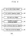
- Fig. 2 shows a setting program 42 of the embodiments.
- the setting program 42 is a part of the knit designing program.
- a setting data storage command 43 is a command to store the data on the unit pattern and setting patterns, and the setting area
- a unit pattern expanding command 44 is a command to expand the unit pattern in the setting area
- an area modifying command 45 is a command to detect a change in the external shape of the knitted fabric and modifies the setting area.
- a formation procedure processing command 46 is a command to perform processing on the formation procedures, and to particularly detect the circumferential direction of the carrier.
- a level difference detecting command 47 is a command to detect whether or not a level difference is generated between the front and rear setting patterns.
- a front/rear correcting command 48 is a command to eliminate a level difference if there is any, by moving either the front or rear setting pattern vertically by one course.
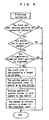
- Fig. 3 shows the entire design of the knit product, including mainly the design of the setting pattern.
- the external shape data of a tubular knitted fabric is created, the shape of an existing knit product is read by, for example, the scanner 14, or the external shape data is read by the disk drive 16.
- the stylus 10 or the like modifies the external shape data.
- structural patterns such as ribs or patterns such as intersia or jacquard patterns are input to determine whether to create setting patterns.
- setting areas are determined, and a unit pattern of each setting area is input.
- the setting areas are input so as to be symmetric on the right and left of the knitted fabric in such a manner that, for example, the armholes are input to the right and left knitted fabrics, the waist part is input to the right and left knitted fabrics etc.
- the unit pattern is input to another setting area in a mirror-reversed manner.
- the unit pattern that is input to one of the setting areas is copied to the other setting area.
- This copying is performed so as to fold back the unit pattern with respect to the boundary between the front and rear knitted fabrics.
- the unit pattern is copied so that the same type of stitch appears in the position on each of the front and rear knitted fabrics, the position being located the same number of wales away from the boundary between the front and rear knitted fabrics.
- the unit pattern is copied such that the unit pattern is expanded vertically within each setting area.
- the unit pattern is periodically and repeatedly copied upward, starting from the lowermost course of the setting area, to thereby fill the entire setting area with the unit pattern.
- the setting area is in principle designed on the front and rear knitted fabrics such that it starts with the same course number and ends with the same course number.
- the level difference is generated between the setting patterns on the respective front and rear knitted fabrics is detected, and, if the level difference is generated, the level difference between the front and rear setting patterns is corrected.
- the design is displayed on the monitor so that the user can evaluate the design, and when modifying the design the user returns to the second connector.
- the formation data is created and the designing is ended.
- Fig. 4 shows an algorithm for determining the setting area.
- the user uses the stylus or the like to designate two corners (characteristic points) at respective both end sections of the setting area.
- the user then inputs the number of wales for expanding the setting pattern inward from the edge of each knitted fabric.
- the number of wales is called "the number of settings.”
- the area that is located between the two characteristic points and located inward by the number of settings away from the edge of the knitted fabric is taken as the setting area.
- the places to which the characteristic points are moved are extracted, and the moved characteristic points and the input number of settings are used to modify the setting area.
- Fig. 5 shows an algorithm for performing front/rear correction. If the front and rear setting patterns are connected in the form of a cylinder, and the unit pattern of each of the setting patterns is configured by two or more courses, this part is the target of front/rear correction.
- the circumferential formation start position is present between the setting patterns on the respective front and rear knitted fabrics, front/rear correction is performed.
- the circumferential formation start side is the target of sliding, wherein the setting pattern at the uppermost level is backed up by one course, and the setting pattern of another course is slid upward from the bottom by one course. Then, the backed upsetting pattern is drawn to the lowermost course.
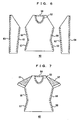
- Fig. 6 shows an example of a sweater 50.
- Reference numerals 53 through 64 represent the setting areas respectively
- reference numerals 55 and 56 represent the waist side setting areas respectively
- reference numerals 57 and 58 also represent the same setting areas respectively.
- Reference numerals 61 and 62 represent lower sleeve side setting areas respectively
- reference numerals 63 and 64 represent sleeve cap side setting areas respectively.
- These setting areas are constituted so as to be symmetric on the right and left of each of the front and rear knitted fabrics, except for the setting areas 53 and 54 corresponding to the collar.
- the shape of each setting area is input by the user using the stylus or the like.
- setting areas may be provided around the armholes and the like, but the front and rear setting areas are separated at the sleeves, thus no level difference is generated. For this reason, the explanation of the setting areas around the armholes is omitted.
- Fig. 7 shows a short-sleeved sweater 60 in which the entire sleeves are provided with large setting patterns 51 and 52, and this figure illustrates a front fabric having the sleeves attached thereto.
- the setting areas 51 and 52 are symmetric on the right and left, and a rear fabric is also provided with the unshown setting areas such that the setting areas continue to the setting areas 51 and 52 and in the course direction and such that the number of setting courses are the same as the number of courses.
- the section within the unit pattern in each of the setting areas 51 and 52 is treated as a valid section, and the rest of the section is treated as an invalid section.
- the unit area is copied in the course direction and the wale direction and expanded to the entire setting areas 51 and 52.
- the section above the underarms is circumferentially formed as one whole cylinder, a level difference is generated between the front and rear setting areas at the side where there is a circumferential formation start point.
- the setting area located on the side where circumferential formation is started from the circumferential formation start point is slid upward by one course.
- the formation data of, for example, the course therebelow is copied.
- another setting pattern may be slid downward by one course.
- the level difference is generated only in either the left or right setting areas 51 or 52, i.e., on the side having the start point for starting circumferential formation.
- Fig. 8 shows an example of a change of a setting area, the change being caused by a change in the external shape.
- the setting area 57 is designated, characteristic points P1 and P2 at respective upper and lower ends of, for example, a waist are designated, and the area that extends inward by the number of settings from a knitted fabric edge 68 for connecting the characteristic points P1 and P2 is taken as the setting area 57.
- a setting layer 66 containing the setting area 57 is defined, and data on the shape of the setting area and on the setting pattern expanded within the setting area are taken as the data on the layer 66.
- the external shape of the knitted fabric is changed, whereby the characteristic point P1 is moved to P1'.
- the area modifying section 28 detects that the characteristic point P1 is moved to P1' and that the edge is changed to an edge 68', and modifies the data so that a setting area 57' and a layer 66' are obtained.
- the characteristic point corresponds to the characteristics of the external shape of the knitted fabric, thus a change of the characteristic point can be extracted when the external shape is changed.
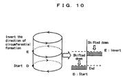
- Fig. 9 shows a location where a level difference is generated.
- circumferential formation 70 is performed from a start point A toward an end point B.
- the start point A and the end point B are located at the boundary between the front knitted fabric and the rear knitted fabric, and the boundary on the opposite side is a half-cycle point C.
- the formation data on this half-cycle point C is as shown in the second drawing from the bottom of Fig. 9 , wherein reference numeral 74 represents rear knitted fabric data, and reference numeral 75 represents front knitted fabric data.
- formation is performed starting from the start point A to the half-cycle point C on the rear knitted fabric side, and then formation is performed on the front knitted fabric side.
- a stitch array 76 on the formation data one circle of stitches is tubularly connected.
- the end point B is connected to a stitch located on one course above the start point A, so stitch arrays 72 and 73 in a natural state are as shown in the top of Fig. 9 , whereby a level difference equivalent to one course is generated between the setting pattern in the A section and the setting pattern in the B section.
- the start point A and the end point B are connected vertically to each other in the wale direction as long as the direction of circumferential formation is not inverted during the formation. Therefore, the start point A is a start point obtained when the circumferential formation is started, and the end point B is an end point obtained at the first one cycle of circumferential formation. If the direction of circumferential formation is inverted during the formation, the relationship between the start point and the end point is reversed. For example, suppose that the circumferential formation is started at D shown in Fig. 10 , and the direction of circumferential formation is inverted at E.
- the setting pattern to be shifted down in the section between D and E and the setting pattern to be shifted down in the section above E are reversed.
- the start point and the end point may be defined along the direction of circumferential formation that is obtained after the inversion.
- Fig. 11 shows the correction performed at the location where the level difference is generated.
- setting patterns 90 and 91 exist in a continuous fashion on both sides of the circumferential formation start point. Further, each hatching indicates the type of stitches or one course of patterns.
- the setting pattern 90 on the start point side is shifted down by one course with respect to the setting pattern 91 on the end point side.
- one course of data at the uppermost level is backed up, the rest of data 93 is slid upward by one course, and the backed up data 92 at the uppermost level is copied to the lowermost course.
- the whole setting pattern 90 may be slid upward by one course, but in this case an area having no designated stitch type remains in the lowermost course of the setting pattern 90. Therefore, the type of a stitch needs to be input into this section.
- the data 92 of the uppermost level is copied to the lowermost level.
- the setting pattern 90 is obtained by repeatedly and periodically forming a unit pattern, and deterioration of the beauty thereof is prevented by connecting the pattern of the lowermost course to the pattern of the uppermost course. Also, in the processing shown in Fig. 11 , the processing is pointless if the unit pattern is constituted by one course, thus the processing is not performed.
- a setting pattern can be designed without considering a change of the external shape of each of the knitted fabric, and the setting pattern does not become discontinuous at the boundary between the front and rear knitted fabrics.
- level difference correction is performed. Then the user displays the design on the monitor and evaluates the design obtained after level difference correction. Therefore, the user can design the setting pattern without considering the level difference. However, the level difference may be corrected when the design is determined.
Description
- The present invention relates to designing a tubular knit product by using a flat-knitting machine.
- In most knit products such as a sweater, a vest and a one-piece garment, a setting is formed on each end section of a knitted fabric. The setting is configured from structural patterns constituting a width of approximately several wales from the end section of the knitted fabric, and has a structural design that is different from the design of the other sections of the knitted fabric. When, for example, forming a front fabric and a rear fabric simultaneously or when forming both sleeves of the front fabric and rear fabric simultaneously by circumferentially forming in a tubular form, settings are formed on the armholes, waist, collar, inside and outside of the sleeves and the like of the front and rear fabrics. In this case, the inside or the outside of the waist and each sleeve is a section for connecting the front and rear knitted fabrics.
- The applicant has proposed in
WO 04/088022A1 - It is preferred that the shape of the setting area be altered when the external design of the knit product is altered. However, the inventor has focused attention on that the method described in
WO 04/088022A1 - An object of the present invention is to easily design a setting pattern by:
- 1) Altering a setting area in response to an alteration of the external shape of a knit product; and
- 2) Preventing the setting pattern from being shifted vertically at each side of the circumferential formation start point, when circumferentially forming the knit product.
A secondary object of the present invention is: - 3) To prevent the occurrence of an area that has no data on a type of a stitch, when preventing the setting pattern from being shifted vertically.
- The designing device of the present invention is a device for creating design data of a knit product in order to form a cylindrically-shaped fabric constituted by front and rear knitted fabrics by means of a flat-knitting machine by circumferentially moving a yarn carrier, and to form a setting pattern on an end section of each of the knitted fabrics, the device being provided with: designating means for accepting that a setting area is designated and storing the designated setting area in association with an external shape of each of the knitted fabrics; modifying means for modifying the setting area in response to an alteration of an external design of each of the knitted fabrics; expanding means for storing data on the setting pattern and expanding the pattern through the entire setting area; detecting means for detecting that the setting area exists in both circumferential direction start section and end section located respectively on both sides of a carrier circumferential movement start section and that the setting area also exists so as to continue along a course direction between the start section and the end section; and correcting means for moving on the data, at the time of the detection, the setting pattern located on the start section side relatively upward to the end section side by one course.
- Preferably, the designating means accepts that the both end sections of the setting area are designated, stores the designated both end sections in association with the external shape of each of the knitted fabrics, and stores an area of a predetermined number of wales between the designated ends as the setting area, the predetermined number of wales being counted inward from an edge of each of the knitted fabrics. Also, preferably the modifying means moves both of the end sections in response to the alteration of the external design of each of the knitted fabrics, and the expanding means stores data on a pattern in units of the setting pattern, and copies the data so that the pattern spreads through the entire setting area.
- It is particularly preferred that, on the start section side, the correcting means move, on the data, the uppermost course of the setting pattern to the lowermost course of the setting pattern, and shift on the data a setting pattern of another course upward by one course.
- The designing method of the present invention is a method of creating design data of a knit product in order to form a cylindrically-shaped fabric constituted by front and rear knitted fabrics by means of a flat-knitting machine by circumferentially moving a yarn carrier, and to form a setting pattern on an end section of each of the knitted fabrics, the method comprising: accepting that a setting area is designated and storing the designated setting area in association with an external shape of each of the knitted fabrics; modifying the setting area in response to an alteration of an external design of each of the knitted fabrics; storing data on the setting pattern and expanding the pattern through the entire setting area; and when detection is made that the setting area exists in both circumferential direction start section and end section located respectively on both sides of a carrier circumferential movement start section and that the setting area also exists so as to continue along a course direction between the start section and the end section, moving on the data the setting pattern located on the start section side relatively upward to the end section side by one course.
- Preferably, in the designating, designation of the both end sections of the setting area is accepted, the designated both end sections are stored in association with the external shape of each of the knitted fabrics, and an area of a predetermined number of wales between the designated ends is stored as the setting area, the predetermined number of wales being counted inward from an edge of each of the knitted fabrics. In the modifying, the both end sections are moved in response to the alteration of the external design of each of the knitted fabrics. In the expanding, data on a pattern in units of the setting pattern is stored and then copied so that the pattern spreads through the entire setting area.
- It is particularly preferred that, in the upward movement by one course, on the start section side, the uppermost course of the setting pattern is moved on the data to the lowermost course of the setting pattern, and a setting pattern of another course is shifted on the data upward by one course.
- A corresponding designing program is a program for creating design data of a knit product in order to form a cylindrically-shaped fabric constituted by front and rear knitted fabrics by means of a flat-knitting machine by circumferentially moving a yarn carrier, and to form a setting pattern on an end section of each of the knitted fabrics, the program being provided with: a designating command for accepting that a setting area is designated and storing the designated setting area in association with an external shape of each of the knitted fabrics; a modifying command for modifying the setting area in response to an alteration of an external design of each of the knitted fabrics; an expanding command for storing data on the setting pattern and expanding the pattern through the entire setting area; a detecting command for detecting that the setting area exists in both circumferential direction start section and end section located respectively on both sides of a carrier circumferential movement start section and that the setting area also exists so as to continue along a course direction between the start section and the end section; and a correcting command for moving on the data, at the time of the detection, the setting pattern located on the start section side relatively upward to the end section side by one course.
- Preferably, the designating command is used to accept that the both end sections of the setting area are designated, store the designated both end sections in association with the external shape of each of the knitted fabrics, and store an area of a predetermined number of wales between the designated ends as the setting area, the predetermined number of wales being counted inward from an edge of each of the knitted fabrics. Also, preferably the modifying command is used to move the both end sections in response to the alteration of the external design of each of the knitted fabrics, and the expanding command is used to store data on a pattern in units of the setting pattern, and to copy the data so that the pattern spreads through the entire setting area.
- It is particularly preferred that, on the start section side, the correcting command be used to move, on the data, the uppermost course of the setting pattern to the lowermost course of the setting pattern, and to shift setting pattern, on the data, of another course upward by one course.
- Since the present invention relates to designing a knit program, the concepts of the external shape of a knitted fabric, the setting area, the setting patterns and the like are the same as the concept on the design data of the knit product. Furthermore, "course" means a row of stitches arranged in the horizontal direction of the knitted fabric, and "wale" means a row of stitches arranged in the vertical direction of the knitted fabric. Relative movement by one course includes moving one of the setting pattern data items upward and moving another one downward. In the present specification, the descriptions related to the designing device for designing a knit product are directly applied to the designing method and designing program, while the descriptions related to the designing method are directly applied to the designing device and designing program. Designation of both end sections of a setting area means to designate, for example, characteristic points of the both end sections.
- According to the present invention, since the setting area is stored in association with the data on the external shape of each knitted fabric, the setting area is altered if the external shape of the knitted fabric is altered. Therefore, it is not necessary to redesign the setting patterns in response to the alteration of the external shape of the knitted fabric.
- Also, according to the present invention, if the setting area exists on each side of the carrier circumferential movement start section, the setting pattern on the start section side is relatively slid upward by one course toward the end section side. Accordingly, the setting patterns of the front and rear knitted fabrics can be prevented from becoming discontinuous in the course direction.
- Here, on the data the uppermost course of the setting pattern on the start section side is moved to the lowermost course of the setting pattern, and setting pattern, on the data, of another course is shifted upward by one course so that the setting area itself does not move vertically. Therefore, the data on the type of a stitch can be prevented from being lost in the lowermost course of the setting area.
-
-
Fig. 1 is a block diagram of a knit designing device of embodiments; -
Fig. 2 is a substantial block diagram of the knit designing program of the embodiments; -
Fig. 3 is a flowchart showing an overview of a knit design according to the embodiments; -
Fig. 4 is a flowchart showing an algorithm for determining a setting area according to the embodiments; -
Fig. 5 is a flowchart showing an algorithm for correcting setting patterns on the front and rear knitted fabrics according to the embodiments; -
Fig. 6 is a view schematically showing an example of the setting area; -
Fig. 7 is a view schematically showing a modification of the setting area; -
Fig. 8 is a view schematically showing a change of the setting area of the embodiments, the change being caused in response to a change of the external shape; -
Fig. 9 is a view showing a mechanism in which a level difference is generated between the front and rear setting patterns during tubular formation; -
Fig. 10 is a view schematically showing the orientation of the level difference when a circumferential direction is changed in mid-course; and -
Fig. 11 is a view schematically showing how front/rear correction is performed on the setting patterns according to the embodiments. - 2 knit designing
device 4 bus 6color monitor 8keyboard 10stylus 12digitizer 14color scanner 16disk drive 18color printer 20communication interface 22 external shapedata storage section 24 settingdata storage section 26 unitpattern expanding section 28area modifying section 30 formationprocedure processing section 32 leveldifference detecting section 34 front/rear correction section 36 formation data creating section 38simulation section 40 flat-knitting machine 42setting program 43 settingdata storage command 44 unit pattern expanding command 45area modifying command 46 formationprocedure processing command 47 leveldifference detecting command 48 front/rear correction command 50sweater 51 through 64 settingarea 66, 66'setting layer 68, 68'edge 70circumferential formation natural state 74 rear knittedfabric data 75 front knitted fabric data 76 stitch array onformation data setting pattern 92 data ofuppermost level 93 data of levels other than uppermost level P1, P2, P2' characteristic point A start point B end point C half-cycle point D start point E inverted section - The best embodiments for carrying out the present invention are described hereinafter.
-
Fig. 1 through Fig. 11 show the embodiments. In these figures,reference numeral 2 represents a knit designing device, andreference numeral 4 represents a bus. Regarding an input/output system, reference numeral 6 represents a color monitor,reference numeral 8 represents a keyboard,reference numeral 10 represents a stylus, andreference numeral 12 represents a digitizer. A position on design data is designated by thestylus 10 anddigitizer 12 to input a graphic image.Reference numeral 14 represents a color scanner,reference numeral 16 represents a disk drive,reference numeral 18 represents a color printer, andreference numeral 20 represents a communication interface. - A knitted fabric to be designed has a tubular shape and comprises, for example, a front fabric, a rear fabric, and/or sleeves attached to these fabrics. The types of a knit product include a sweater, a vest, a one-piece garment, a pair of pants, a pair of slacks, and the like. An external shape
data storage section 22 stores data on the external shape of the knit product in units of the front and rear knitted fabrics, wherein the knitted fabrics used as the unit are, for example, a front fabric, a rear fabric, a right front sleeve, a right rear sleeve, a left front sleeve and a rear left sleeve. - A setting
data storage section 24 stores data on setting patterns and a setting area for each setting area. Setting areas are, for example, armholes of the front and rear fabrics, waist, collar, rear shoulder, and the like. Settings are formed on the lower sleeve sections or sleeve caps on both sleeves of the front and rear knitted fabrics. Design layers are provided in the setting areas respectively, and setting data is stored as data on each layer. Also, each setting area is an area within the layer. A unitpattern expanding section 26 vertically copies and expands a unit pattern, which is a unit of the setting pattern, into the setting area. The unit pattern consists of approximately one through several courses in height, and approximately several wales in width, which is counted inward from an edge of the knitted fabric. A pattern in which the unit pattern is repeated periodically is the setting pattern. Furthermore, the unit pattern cannot be broken into smaller patterns. The unit pattern is stored in the settingdata storage section 24, unitpattern expanding section 26 or the like. - An
area modifying section 28 alters the setting area in response to an alteration of the external shape data stored in the external shapedata storage section 22. The settingdata storage section 24 stores the setting area by means of a characteristic point on the external shape of each of the knitted fabrics. When the external shape data is altered the characteristic point is moved, thus the setting area can be changed accordingly. The setting area may be stored by means of the characteristic point on the external shape that is altered as the external shape data of the knitted fabric is altered, and it is not always necessary to store the characteristic point. A formationprocedure processing section 30 makes a determination on the formation procedures, such as which carrier should be allocated to which part of the knitted fabric for formation, which direction to circumferentially move the carrier, and therefore how the carrier of the flat-knitting machine should be moved. Standard conditions, for example, may be stored to allocate the formation procedures automatically, and only when a particular procedure is used a user may designate such particular procedure. In the embodiments, a tubular knitted fabric is formed, thus the carrier circumferentially moves along the knitted fabric. Such formation is called "circumferential formation." - A level
difference detecting section 32 detects a level difference generated between the setting patterns at the boundary between the front and rear knitted fabrics. Generally, circumferential formation is started from the boundary between the front and rear knitted fabrics, and the level difference is generated between a wale start side and a wale end side of the circumferential formation start point. Therefore, the level difference is generated at, for example, the boundary between the front and rear knitted fabrics. The place where the level difference is generated is located between the start side and the end side of the circumferential formation start point. A front/rear correcting section 34 shifts the setting pattern located on the circumferential formation start side, upward by one course with respect to the section where the level difference is generated, corrects the level difference generated between the setting patterns on the respective front and rear knitted fabrics, and changes the front and rear setting patterns to patterns that are continuous in the course direction. A formationdata creating section 36 creates formation data for the designed knit product, and a simulation section 38 performs visual simulation on the knit product on the basis of the created formation data. The formation data is input to a flat-knitting machine 40 via communication or a disk, whereby the flat-knitting machine 40 forms a sweater or the like. -
Fig. 2 shows asetting program 42 of the embodiments. Thesetting program 42 is a part of the knit designing program. A settingdata storage command 43 is a command to store the data on the unit pattern and setting patterns, and the setting area, a unitpattern expanding command 44 is a command to expand the unit pattern in the setting area, and an area modifying command 45 is a command to detect a change in the external shape of the knitted fabric and modifies the setting area. A formationprocedure processing command 46 is a command to perform processing on the formation procedures, and to particularly detect the circumferential direction of the carrier. A leveldifference detecting command 47 is a command to detect whether or not a level difference is generated between the front and rear setting patterns. A front/rear correcting command 48 is a command to eliminate a level difference if there is any, by moving either the front or rear setting pattern vertically by one course. -
Fig. 3 shows the entire design of the knit product, including mainly the design of the setting pattern. First, the external shape data of a tubular knitted fabric is created, the shape of an existing knit product is read by, for example, thescanner 14, or the external shape data is read by thedisk drive 16. Then, thestylus 10 or the like modifies the external shape data. Moreover, structural patterns such as ribs or patterns such as intersia or jacquard patterns are input to determine whether to create setting patterns. - When creating setting patterns, setting areas are determined, and a unit pattern of each setting area is input. In the case in which the setting areas are input so as to be symmetric on the right and left of the knitted fabric in such a manner that, for example, the armholes are input to the right and left knitted fabrics, the waist part is input to the right and left knitted fabrics etc., if a unit pattern is input to one of the setting areas, the unit pattern is input to another setting area in a mirror-reversed manner. Also, in the case in which the setting areas are provided in a continuous manner in an end section of each of the front and rear knitted fabrics, i.e., each of the front and rear waists, front and rear lower sleeve sections, or each of the front and rear sleeve caps, the unit pattern that is input to one of the setting areas is copied to the other setting area. This copying is performed so as to fold back the unit pattern with respect to the boundary between the front and rear knitted fabrics. Specifically, the unit pattern is copied so that the same type of stitch appears in the position on each of the front and rear knitted fabrics, the position being located the same number of wales away from the boundary between the front and rear knitted fabrics.
- The unit pattern is copied such that the unit pattern is expanded vertically within each setting area. For example, the unit pattern is periodically and repeatedly copied upward, starting from the lowermost course of the setting area, to thereby fill the entire setting area with the unit pattern. It should be noted that the setting area is in principle designed on the front and rear knitted fabrics such that it starts with the same course number and ends with the same course number.
- Whether or not the level difference is generated between the setting patterns on the respective front and rear knitted fabrics is detected, and, if the level difference is generated, the level difference between the front and rear setting patterns is corrected. Next, the design is displayed on the monitor so that the user can evaluate the design, and when modifying the design the user returns to the second connector. However, when the design is not modified, the formation data is created and the designing is ended.
-
Fig. 4 shows an algorithm for determining the setting area. In the case in which modification of the external shape data of the knit product does not have to be considered in the initial stage of the designing, the user uses the stylus or the like to designate two corners (characteristic points) at respective both end sections of the setting area. The user then inputs the number of wales for expanding the setting pattern inward from the edge of each knitted fabric. The number of wales is called "the number of settings." Then, the area that is located between the two characteristic points and located inward by the number of settings away from the edge of the knitted fabric is taken as the setting area. In the case in which the external shape of the knitted fabric is modified, the places to which the characteristic points are moved are extracted, and the moved characteristic points and the input number of settings are used to modify the setting area. -
Fig. 5 shows an algorithm for performing front/rear correction. If the front and rear setting patterns are connected in the form of a cylinder, and the unit pattern of each of the setting patterns is configured by two or more courses, this part is the target of front/rear correction. When the circumferential formation start position is present between the setting patterns on the respective front and rear knitted fabrics, front/rear correction is performed. In this case, the circumferential formation start side is the target of sliding, wherein the setting pattern at the uppermost level is backed up by one course, and the setting pattern of another course is slid upward from the bottom by one course. Then, the backed upsetting pattern is drawn to the lowermost course. -
Fig. 6 shows an example of asweater 50.Reference numerals 53 through 64 represent the setting areas respectively,reference numerals reference numerals Reference numerals reference numerals setting areas -
Fig. 7 shows a short-sleeved sweater 60 in which the entire sleeves are provided withlarge setting patterns areas setting areas areas areas areas entire setting areas areas triangular setting areas - When forming the
sweater 60, the section above the underarms is circumferentially formed as one whole cylinder, a level difference is generated between the front and rear setting areas at the side where there is a circumferential formation start point. Here, for example, the setting area located on the side where circumferential formation is started from the circumferential formation start point is slid upward by one course. To the lowermost course that no longer has a pattern, the formation data of, for example, the course therebelow is copied. Instead of sliding one of the setting patterns upward by one course, another setting pattern may be slid downward by one course. It should be noted that the level difference is generated only in either the left orright setting areas -
Fig. 8 shows an example of a change of a setting area, the change being caused by a change in the external shape. In the case in which thesetting area 57 is designated, characteristic points P1 and P2 at respective upper and lower ends of, for example, a waist are designated, and the area that extends inward by the number of settings from a knittedfabric edge 68 for connecting the characteristic points P1 and P2 is taken as the settingarea 57. Then, asetting layer 66 containing the settingarea 57 is defined, and data on the shape of the setting area and on the setting pattern expanded within the setting area are taken as the data on thelayer 66. Here, the external shape of the knitted fabric is changed, whereby the characteristic point P1 is moved to P1'. Thearea modifying section 28 detects that the characteristic point P1 is moved to P1' and that the edge is changed to an edge 68', and modifies the data so that a setting area 57' and a layer 66' are obtained. The characteristic point corresponds to the characteristics of the external shape of the knitted fabric, thus a change of the characteristic point can be extracted when the external shape is changed. -
Fig. 9 shows a location where a level difference is generated. For example,circumferential formation 70 is performed from a start point A toward an end point B. The start point A and the end point B are located at the boundary between the front knitted fabric and the rear knitted fabric, and the boundary on the opposite side is a half-cycle point C. The formation data on this half-cycle point C is as shown in the second drawing from the bottom ofFig. 9 , whereinreference numeral 74 represents rear knitted fabric data, andreference numeral 75 represents front knitted fabric data. Here, formation is performed starting from the start point A to the half-cycle point C on the rear knitted fabric side, and then formation is performed on the front knitted fabric side. In a stitch array 76 on the formation data, one circle of stitches is tubularly connected. However, in an actual knitted fabric, the end point B is connected to a stitch located on one course above the start point A, so stitcharrays Fig. 9 , whereby a level difference equivalent to one course is generated between the setting pattern in the A section and the setting pattern in the B section. - To describe the start point and the end point, the start point A and the end point B are connected vertically to each other in the wale direction as long as the direction of circumferential formation is not inverted during the formation. Therefore, the start point A is a start point obtained when the circumferential formation is started, and the end point B is an end point obtained at the first one cycle of circumferential formation. If the direction of circumferential formation is inverted during the formation, the relationship between the start point and the end point is reversed. For example, suppose that the circumferential formation is started at D shown in
Fig. 10 , and the direction of circumferential formation is inverted at E. Consequently, the setting pattern to be shifted down in the section between D and E and the setting pattern to be shifted down in the section above E are reversed. In other words, if the direction of circumferential formation is inverted during the formation, the start point and the end point may be defined along the direction of circumferential formation that is obtained after the inversion. -
Fig. 11 shows the correction performed at the location where the level difference is generated. Suppose that settingpatterns pattern 90 on the start point side is shifted down by one course with respect to thesetting pattern 91 on the end point side. When correction is performed on such shifting, one course of data at the uppermost level is backed up, the rest ofdata 93 is slid upward by one course, and the backed updata 92 at the uppermost level is copied to the lowermost course. - The
whole setting pattern 90 may be slid upward by one course, but in this case an area having no designated stitch type remains in the lowermost course of thesetting pattern 90. Therefore, the type of a stitch needs to be input into this section. In order to avoid this input work, thedata 92 of the uppermost level is copied to the lowermost level. It should be noted that thesetting pattern 90 is obtained by repeatedly and periodically forming a unit pattern, and deterioration of the beauty thereof is prevented by connecting the pattern of the lowermost course to the pattern of the uppermost course. Also, in the processing shown inFig. 11 , the processing is pointless if the unit pattern is constituted by one course, thus the processing is not performed. - In the embodiments, a setting pattern can be designed without considering a change of the external shape of each of the knitted fabric, and the setting pattern does not become discontinuous at the boundary between the front and rear knitted fabrics. In the embodiments, if a level difference is generated between the front and rear setting patterns at the stage of creating the setting pattern, level difference correction is performed. Then the user displays the design on the monitor and evaluates the design obtained after level difference correction. Therefore, the user can design the setting pattern without considering the level difference. However, the level difference may be corrected when the design is determined.
The objects are also met by a designing method according to
Claims (6)
- A designing device (2) for creating design data of a knit product in order to form a cylindrically-shaped fabric constituted by front and rear knitted fabrics that are circumferentially formed starting from a boundary between them by means of a flat-knitting machine (40) by circumferentially moving a yarn carrier, and to form a setting pattern (90, 91) on a start and end section on each side of the boundary, the designing device (2) being chracterized by:designating means for designating a setting area and storing the designated setting area (51 to 64) in association with the data on an external shape of each of the front and rear knitted fabrics;modifying means for modifying the setting area (51 to 64) in response to an alteration of an external shape of each of the front and rear knitted fabrics;expanding means (26) for storing data on a pattern in units of the setting pattern (90, 91) and expanding the pattern through the entire setting area (51 to 64);level difference detecting means (32) for detecting that the setting area exists at both the start section and the end section of the circumferential yarn carrier movement located on both sides of the boundary between the front and rear knitted fabric; that the setting areas are connected along a course direction between the start section and the end section and if a level difference is generated between the setting patterns at the boundary between the front and rear knitted fabrics andfront/rear correcting means (34) for shifting the data, in case of a detection, such that the setting pattern (51 to 64) located on the start section side, is shifted upward by one course relative to the end section side thereby changing the front and rear setting patterns to patterns that are continuous in the course direction.
- The designing device according to Claim 1, wherein
the designating means designates the start and end section of the setting area (51 to 64), stores both sections in association with the external shape of each of the front and rear knitted fabrics, and stores an area of a predetermined number of wales between the designated sections as the setting area (51 to 64), the predetermined number of wales being counted inward from an edge of each of the knitted fabrics,
the modifying means moves both of the start and end section in response to the alteration of the external design of each of the front and rear knitted fabrics, and
the expanding means stores data on a pattern in units of the setting pattern (90, 91), and copies the data so that the pattern spreads through the entire setting area (51 to 64). - The designing device according to Claim 1, wherein, on the start section side, the front/rear correcting means moves the data of the uppermost course (92) of the setting pattern (90, 91) to the lowermost course of the setting pattern (90, 91), and shifts the data of a setting pattern of another course (93) upward by one course.
- A designing method of creating design data of a knit product in order to form a cylindrically-shaped fabric constituted by front and rear knitted fabrics that are circumferentially formed starting from a boundary between them by means of a flat-knitting machine (40) by circumferentially moving a yarn carrier, and to form a setting pattern (90, 91) on a start and end section on each side of the boundary, characterized in that the designing method comprises:designating a setting area (51 to 64) and storing the designated setting area (51 to 64) in association with the data on an external shape of the front and rear knitted fabrics;modifying the setting area (51 to 64) in response to an alteration of an external shape of each of the front and rear knitted fabrics;storing data on a pattern in units of the setting pattern (90, 91) and expanding the pattern through the entire setting area (51 to 64); andwhen it is detected that the setting area (51 to 64) exists at the start section and end section of the circumferential yarn carrier movement located on both sides of the boundary between the front and rear knitted fabric; that the setting areas are connected along a course direction between the start section and the end section; and that a level difference is generated between the setting patterns at the boundary between the front and rear knitted fabrics; then shifting the data such that the setting pattern (90, 91) located on the start section side is shifted upward by one course relative to the end section side thereby changing the front and rear setting patterns to patterns that are continuous in the course direction.
- The designing method according to Claim 4, wherein
in the designating, both the start and end section of the setting area (51 to 64) are designated, both sections are stored in association with the external shape of each of the front and rear knitted fabrics, and an area of a predetermined number of wales between the designated sections is stored as the setting area (51 to 64), the predetermined number of wales being counted inward from an edge of each of the knitted fabrics,
in the modifying, both the start and end section are moved in response to the alteration of the external design of each of the knitted fabrics, and
in the expanding, data on a pattern in units of the setting pattern (90, 91) is stored and then copied so that the pattern spreads through the entire setting area (51 to 64). - The designing method according to Claim 4, wherein in the upward movement by one course, on the start section side, the data of the uppermost course (92) of the setting pattern (90, 91) is moved to the lowermost course of the setting pattern (90, 91), and the data of a setting pattern (90, 91) of another course (93) is shifted upward by one course.
Applications Claiming Priority (2)
| Application Number | Priority Date | Filing Date | Title |
|---|---|---|---|
| JP2005042498A JP4366321B2 (en) | 2005-02-18 | 2005-02-18 | Knitting product design apparatus and design method, and program thereof |
| PCT/JP2006/301954 WO2006087929A1 (en) | 2005-02-18 | 2006-02-06 | Designing device, method and program of knit product |
Publications (3)
| Publication Number | Publication Date |
|---|---|
| EP1849902A1 EP1849902A1 (en) | 2007-10-31 |
| EP1849902A4 EP1849902A4 (en) | 2013-09-04 |
| EP1849902B1 true EP1849902B1 (en) | 2015-05-13 |
Family
ID=36916338
Family Applications (1)
| Application Number | Title | Priority Date | Filing Date |
|---|---|---|---|
| EP20060713097 Not-in-force EP1849902B1 (en) | 2005-02-18 | 2006-02-06 | Designing device and knitting method |
Country Status (6)
| Country | Link |
|---|---|
| US (1) | US7664564B2 (en) |
| EP (1) | EP1849902B1 (en) |
| JP (1) | JP4366321B2 (en) |
| KR (1) | KR101155979B1 (en) |
| CN (1) | CN101124356B (en) |
| WO (1) | WO2006087929A1 (en) |
Families Citing this family (12)
| Publication number | Priority date | Publication date | Assignee | Title |
|---|---|---|---|---|
| CN102076897B (en) * | 2008-06-30 | 2012-05-30 | 株式会社岛精机制作所 | Design device and design method for knitted fabric using intarsia jacquard |
| US8175741B2 (en) * | 2009-12-22 | 2012-05-08 | Ko Young-A | Method for creating panels and pattern-making |
| DE102010053866B4 (en) * | 2010-12-08 | 2012-08-30 | H. Stoll Gmbh & Co. Kg | Method of designing a molded fabric based on vector contour data and design means |
| JP5800530B2 (en) * | 2011-02-28 | 2015-10-28 | 株式会社島精機製作所 | Knit design device and knit design method |
| JP5732321B2 (en) * | 2011-06-08 | 2015-06-10 | 株式会社島精機製作所 | Knit design method and apparatus |
| CN102864566B (en) * | 2012-09-29 | 2014-02-12 | 加宝利服装有限公司 | Fabric manufacture method, manufacture control method, manufacture control device and manufacture system |
| US11131045B2 (en) | 2014-09-15 | 2021-09-28 | Nimbly, Inc. | Systems, methods, and software for manufacturing a knitted article |
| US10351982B2 (en) * | 2014-09-15 | 2019-07-16 | Appalatch Outdoor Apparel Company | Systems, methods, and software for manufacturing a custom-knitted article |
| US11293124B2 (en) * | 2018-05-30 | 2022-04-05 | Nike, Inc. | Textile component production systems and methods |
| US10787756B2 (en) * | 2018-07-24 | 2020-09-29 | Bolt Threads Inc. | Custom sizing system and methods for a knitted garment having radial symmetry |
| CN114541021A (en) * | 2020-11-25 | 2022-05-27 | 南旋实业有限公司 | Knitting method and knitting device |
| US20230147207A1 (en) * | 2021-11-09 | 2023-05-11 | Shanghai Cimpress Technology Company Limited | Method and apparatus for customizing knitted products |
Family Cites Families (16)
| Publication number | Priority date | Publication date | Assignee | Title |
|---|---|---|---|---|
| FR2263321B1 (en) * | 1974-03-04 | 1977-11-18 | Kanebo Ltd | |
| JPS6071748A (en) * | 1983-09-27 | 1985-04-23 | 株式会社島アイデア・センタ− | Recorder of pattern information |
| BR8601696A (en) * | 1985-04-18 | 1986-12-16 | Du Pont | SIMULATION METHOD, BY COMPUTER, OF THE PROPERTIES OF APPEARANCE OF A WARM KNITTED TISSUE |
| JP2656405B2 (en) * | 1991-09-17 | 1997-09-24 | 旭化成工業株式会社 | Knit design system and method of creating knitting data |
| US5557527A (en) * | 1993-08-31 | 1996-09-17 | Shima Seiki Manufacturing Ltd. | Knit design system and a method for designing knit fabrics |
| JPH09111620A (en) * | 1995-10-12 | 1997-04-28 | Tsudakoma Corp | Expression of knitting stitch image in knitted fabric design system |
| DE19901542C2 (en) * | 1999-01-16 | 2002-10-10 | Stoll & Co H | Device for the design of knitted or knitted machine products |
| JP4079883B2 (en) * | 2001-10-05 | 2008-04-23 | 株式会社島精機製作所 | Knit design method and apparatus |
| US7127321B2 (en) * | 2002-08-30 | 2006-10-24 | Shima Seiki Manufacturing, Ltd. | Device for designing tubular knot fabric and method of designing |
| US6845284B2 (en) * | 2003-02-11 | 2005-01-18 | Sara Lee Corporation | Methods and systems for designing circularly knitted garments |
| US7197371B2 (en) * | 2003-03-31 | 2007-03-27 | Shima Seiki Manufacturing, Ltd. | Method and device for knit design |
| US7330772B2 (en) * | 2003-04-04 | 2008-02-12 | Shima Seiki Manufacturing Limited | Knit design method and apparatus |
| DE602004031626D1 (en) * | 2003-04-15 | 2011-04-14 | Shima Seiki Mfg | METHOD AND DEVICE FOR MESH DEVICE DESIGN |
| JP4336155B2 (en) * | 2003-06-30 | 2009-09-30 | 株式会社島精機製作所 | Knit clothing knitting method, knit clothing and knit design device |
| JP4503312B2 (en) * | 2004-02-26 | 2010-07-14 | 株式会社島精機製作所 | Knit garment wearing simulation method and apparatus, and program thereof |
| US7460927B1 (en) * | 2007-12-21 | 2008-12-02 | Freeman Industrial Co., Ltd. | Method of manufacturing knitted fabrics |
-
2005
- 2005-02-18 JP JP2005042498A patent/JP4366321B2/en active Active
-
2006
- 2006-02-06 WO PCT/JP2006/301954 patent/WO2006087929A1/en active Application Filing
- 2006-02-06 KR KR1020077018156A patent/KR101155979B1/en active IP Right Grant
- 2006-02-06 CN CN2006800054236A patent/CN101124356B/en active Active
- 2006-02-06 US US11/816,563 patent/US7664564B2/en not_active Expired - Fee Related
- 2006-02-06 EP EP20060713097 patent/EP1849902B1/en not_active Not-in-force
Also Published As
| Publication number | Publication date |
|---|---|
| JP2006225809A (en) | 2006-08-31 |
| US20090019895A1 (en) | 2009-01-22 |
| JP4366321B2 (en) | 2009-11-18 |
| EP1849902A4 (en) | 2013-09-04 |
| CN101124356A (en) | 2008-02-13 |
| EP1849902A1 (en) | 2007-10-31 |
| KR20070107026A (en) | 2007-11-06 |
| US7664564B2 (en) | 2010-02-16 |
| CN101124356B (en) | 2010-06-23 |
| KR101155979B1 (en) | 2012-06-18 |
| WO2006087929A1 (en) | 2006-08-24 |
Similar Documents
| Publication | Publication Date | Title |
|---|---|---|
| EP1849902B1 (en) | Designing device and knitting method | |
| EP0568700B1 (en) | Knit design system and method of making knitting data therefor | |
| EP1900862B1 (en) | Knit simulation device, knit simulation method, and program therefor | |
| US6611730B1 (en) | Device and method of designing knit products to be manufactured on a knitting machine | |
| US7481078B2 (en) | Knitwear knitted by flat knitting machine and method for knitting the same | |
| JP6541621B2 (en) | Method of knitting tubular knitted fabric, and tubular knitted fabric | |
| WO2005116315A1 (en) | Knitting method for knitting fabric, knitting fabric, and knitting program | |
| KR100706649B1 (en) | Knit design system | |
| JP4852092B2 (en) | Method for forming additional stitches and knitted fabric in which additional stitches are formed on the inner side of the knitting width direction end of the knitted fabric | |
| JP4237753B2 (en) | Knit design method and apparatus, and program | |
| JPWO2011004694A1 (en) | Knitwear having sleeves and body and knitting method thereof | |
| CN103866481B (en) | The braid method of cylindrical fabric and cylindrical fabric | |
| EP2492383B1 (en) | Knit designing device, designing method, and designing program | |
| JP5800530B2 (en) | Knit design device and knit design method | |
| CN113239418B (en) | Pattern plate making method, computer equipment and readable storage medium | |
| JP2006176912A (en) | Method for knitting sleeved knitwear | |
| EP2042632B1 (en) | Simulation device, simulation method and simulation program of tubular fabric | |
| JP2010037701A (en) | Method of knitting cylindrical knit fabric | |
| JPH09209249A (en) | Increase in number of stitches of tubular knitted fabric with flat knitting machine, knit designing apparatus therefor and knitted tubular knitted fabric |
Legal Events
| Date | Code | Title | Description |
|---|---|---|---|
| PUAI | Public reference made under article 153(3) epc to a published international application that has entered the european phase |
Free format text: ORIGINAL CODE: 0009012 |
|
| 17P | Request for examination filed |
Effective date: 20070820 |
|
| AK | Designated contracting states |
Kind code of ref document: A1 Designated state(s): AT BE BG CH CY CZ DE DK EE ES FI FR GB GR HU IE IS IT LI LT LU LV MC NL PL PT RO SE SI SK TR |
|
| DAX | Request for extension of the european patent (deleted) | ||
| A4 | Supplementary search report drawn up and despatched |
Effective date: 20130802 |
|
| RIC1 | Information provided on ipc code assigned before grant |
Ipc: G06F 17/50 20060101ALI20130729BHEP Ipc: D04B 35/00 20060101AFI20130729BHEP |
|
| GRAP | Despatch of communication of intention to grant a patent |
Free format text: ORIGINAL CODE: EPIDOSNIGR1 |
|
| INTG | Intention to grant announced |
Effective date: 20141117 |
|
| GRAS | Grant fee paid |
Free format text: ORIGINAL CODE: EPIDOSNIGR3 |
|
| GRAA | (expected) grant |
Free format text: ORIGINAL CODE: 0009210 |
|
| AK | Designated contracting states |
Kind code of ref document: B1 Designated state(s): AT BE BG CH CY CZ DE DK EE ES FI FR GB GR HU IE IS IT LI LT LU LV MC NL PL PT RO SE SI SK TR |
|
| REG | Reference to a national code |
Ref country code: GB Ref legal event code: FG4D |
|
| REG | Reference to a national code |
Ref country code: CH Ref legal event code: EP |
|
| REG | Reference to a national code |
Ref country code: IE Ref legal event code: FG4D |
|
| REG | Reference to a national code |
Ref country code: AT Ref legal event code: REF Ref document number: 726888 Country of ref document: AT Kind code of ref document: T Effective date: 20150615 |
|
| REG | Reference to a national code |
Ref country code: DE Ref legal event code: R096 Ref document number: 602006045420 Country of ref document: DE Effective date: 20150625 |
|
| REG | Reference to a national code |
Ref country code: AT Ref legal event code: MK05 Ref document number: 726888 Country of ref document: AT Kind code of ref document: T Effective date: 20150513 |
|
| REG | Reference to a national code |
Ref country code: NL Ref legal event code: MP Effective date: 20150513 |
|
| REG | Reference to a national code |
Ref country code: LT Ref legal event code: MG4D |
|
| PG25 | Lapsed in a contracting state [announced via postgrant information from national office to epo] |
Ref country code: LT Free format text: LAPSE BECAUSE OF FAILURE TO SUBMIT A TRANSLATION OF THE DESCRIPTION OR TO PAY THE FEE WITHIN THE PRESCRIBED TIME-LIMIT Effective date: 20150513 Ref country code: ES Free format text: LAPSE BECAUSE OF FAILURE TO SUBMIT A TRANSLATION OF THE DESCRIPTION OR TO PAY THE FEE WITHIN THE PRESCRIBED TIME-LIMIT Effective date: 20150513 Ref country code: FI Free format text: LAPSE BECAUSE OF FAILURE TO SUBMIT A TRANSLATION OF THE DESCRIPTION OR TO PAY THE FEE WITHIN THE PRESCRIBED TIME-LIMIT Effective date: 20150513 Ref country code: PT Free format text: LAPSE BECAUSE OF FAILURE TO SUBMIT A TRANSLATION OF THE DESCRIPTION OR TO PAY THE FEE WITHIN THE PRESCRIBED TIME-LIMIT Effective date: 20150914 |
|
| PG25 | Lapsed in a contracting state [announced via postgrant information from national office to epo] |
Ref country code: IS Free format text: LAPSE BECAUSE OF FAILURE TO SUBMIT A TRANSLATION OF THE DESCRIPTION OR TO PAY THE FEE WITHIN THE PRESCRIBED TIME-LIMIT Effective date: 20150913 Ref country code: GR Free format text: LAPSE BECAUSE OF FAILURE TO SUBMIT A TRANSLATION OF THE DESCRIPTION OR TO PAY THE FEE WITHIN THE PRESCRIBED TIME-LIMIT Effective date: 20150814 Ref country code: BG Free format text: LAPSE BECAUSE OF FAILURE TO SUBMIT A TRANSLATION OF THE DESCRIPTION OR TO PAY THE FEE WITHIN THE PRESCRIBED TIME-LIMIT Effective date: 20150813 Ref country code: AT Free format text: LAPSE BECAUSE OF FAILURE TO SUBMIT A TRANSLATION OF THE DESCRIPTION OR TO PAY THE FEE WITHIN THE PRESCRIBED TIME-LIMIT Effective date: 20150513 Ref country code: LV Free format text: LAPSE BECAUSE OF FAILURE TO SUBMIT A TRANSLATION OF THE DESCRIPTION OR TO PAY THE FEE WITHIN THE PRESCRIBED TIME-LIMIT Effective date: 20150513 |
|
| PG25 | Lapsed in a contracting state [announced via postgrant information from national office to epo] |
Ref country code: DK Free format text: LAPSE BECAUSE OF FAILURE TO SUBMIT A TRANSLATION OF THE DESCRIPTION OR TO PAY THE FEE WITHIN THE PRESCRIBED TIME-LIMIT Effective date: 20150513 Ref country code: EE Free format text: LAPSE BECAUSE OF FAILURE TO SUBMIT A TRANSLATION OF THE DESCRIPTION OR TO PAY THE FEE WITHIN THE PRESCRIBED TIME-LIMIT Effective date: 20150513 |
|
| REG | Reference to a national code |
Ref country code: DE Ref legal event code: R097 Ref document number: 602006045420 Country of ref document: DE |
|
| PG25 | Lapsed in a contracting state [announced via postgrant information from national office to epo] |
Ref country code: SK Free format text: LAPSE BECAUSE OF FAILURE TO SUBMIT A TRANSLATION OF THE DESCRIPTION OR TO PAY THE FEE WITHIN THE PRESCRIBED TIME-LIMIT Effective date: 20150513 Ref country code: CZ Free format text: LAPSE BECAUSE OF FAILURE TO SUBMIT A TRANSLATION OF THE DESCRIPTION OR TO PAY THE FEE WITHIN THE PRESCRIBED TIME-LIMIT Effective date: 20150513 Ref country code: PL Free format text: LAPSE BECAUSE OF FAILURE TO SUBMIT A TRANSLATION OF THE DESCRIPTION OR TO PAY THE FEE WITHIN THE PRESCRIBED TIME-LIMIT Effective date: 20150513 Ref country code: RO Free format text: LAPSE BECAUSE OF NON-PAYMENT OF DUE FEES Effective date: 20150513 |
|
| PLBE | No opposition filed within time limit |
Free format text: ORIGINAL CODE: 0009261 |
|
| STAA | Information on the status of an ep patent application or granted ep patent |
Free format text: STATUS: NO OPPOSITION FILED WITHIN TIME LIMIT |
|
| 26N | No opposition filed |
Effective date: 20160216 |
|
| PG25 | Lapsed in a contracting state [announced via postgrant information from national office to epo] |
Ref country code: BE Free format text: LAPSE BECAUSE OF NON-PAYMENT OF DUE FEES Effective date: 20160229 Ref country code: SI Free format text: LAPSE BECAUSE OF FAILURE TO SUBMIT A TRANSLATION OF THE DESCRIPTION OR TO PAY THE FEE WITHIN THE PRESCRIBED TIME-LIMIT Effective date: 20150513 |
|
| PG25 | Lapsed in a contracting state [announced via postgrant information from national office to epo] |
Ref country code: BE Free format text: LAPSE BECAUSE OF FAILURE TO SUBMIT A TRANSLATION OF THE DESCRIPTION OR TO PAY THE FEE WITHIN THE PRESCRIBED TIME-LIMIT Effective date: 20150513 |
|
| PG25 | Lapsed in a contracting state [announced via postgrant information from national office to epo] |
Ref country code: LU Free format text: LAPSE BECAUSE OF FAILURE TO SUBMIT A TRANSLATION OF THE DESCRIPTION OR TO PAY THE FEE WITHIN THE PRESCRIBED TIME-LIMIT Effective date: 20160206 Ref country code: MC Free format text: LAPSE BECAUSE OF FAILURE TO SUBMIT A TRANSLATION OF THE DESCRIPTION OR TO PAY THE FEE WITHIN THE PRESCRIBED TIME-LIMIT Effective date: 20150513 |
|
| REG | Reference to a national code |
Ref country code: CH Ref legal event code: PL |
|
| GBPC | Gb: european patent ceased through non-payment of renewal fee |
Effective date: 20160206 |
|
| PG25 | Lapsed in a contracting state [announced via postgrant information from national office to epo] |
Ref country code: CH Free format text: LAPSE BECAUSE OF NON-PAYMENT OF DUE FEES Effective date: 20160229 Ref country code: LI Free format text: LAPSE BECAUSE OF NON-PAYMENT OF DUE FEES Effective date: 20160229 |
|
| REG | Reference to a national code |
Ref country code: FR Ref legal event code: ST Effective date: 20161028 |
|
| REG | Reference to a national code |
Ref country code: IE Ref legal event code: MM4A |
|
| PG25 | Lapsed in a contracting state [announced via postgrant information from national office to epo] |
Ref country code: FR Free format text: LAPSE BECAUSE OF NON-PAYMENT OF DUE FEES Effective date: 20160229 Ref country code: IE Free format text: LAPSE BECAUSE OF NON-PAYMENT OF DUE FEES Effective date: 20160206 Ref country code: GB Free format text: LAPSE BECAUSE OF NON-PAYMENT OF DUE FEES Effective date: 20160206 |
|
| PG25 | Lapsed in a contracting state [announced via postgrant information from national office to epo] |
Ref country code: SE Free format text: LAPSE BECAUSE OF FAILURE TO SUBMIT A TRANSLATION OF THE DESCRIPTION OR TO PAY THE FEE WITHIN THE PRESCRIBED TIME-LIMIT Effective date: 20150513 Ref country code: NL Free format text: LAPSE BECAUSE OF FAILURE TO SUBMIT A TRANSLATION OF THE DESCRIPTION OR TO PAY THE FEE WITHIN THE PRESCRIBED TIME-LIMIT Effective date: 20150513 |
|
| PG25 | Lapsed in a contracting state [announced via postgrant information from national office to epo] |
Ref country code: CY Free format text: LAPSE BECAUSE OF FAILURE TO SUBMIT A TRANSLATION OF THE DESCRIPTION OR TO PAY THE FEE WITHIN THE PRESCRIBED TIME-LIMIT Effective date: 20150513 Ref country code: HU Free format text: LAPSE BECAUSE OF FAILURE TO SUBMIT A TRANSLATION OF THE DESCRIPTION OR TO PAY THE FEE WITHIN THE PRESCRIBED TIME-LIMIT; INVALID AB INITIO Effective date: 20060206 |
|
| PG25 | Lapsed in a contracting state [announced via postgrant information from national office to epo] |
Ref country code: TR Free format text: LAPSE BECAUSE OF FAILURE TO SUBMIT A TRANSLATION OF THE DESCRIPTION OR TO PAY THE FEE WITHIN THE PRESCRIBED TIME-LIMIT Effective date: 20150513 |
|
| PGFP | Annual fee paid to national office [announced via postgrant information from national office to epo] |
Ref country code: DE Payment date: 20211214 Year of fee payment: 17 |
|
| PGFP | Annual fee paid to national office [announced via postgrant information from national office to epo] |
Ref country code: IT Payment date: 20220111 Year of fee payment: 17 |
|
| REG | Reference to a national code |
Ref country code: DE Ref legal event code: R119 Ref document number: 602006045420 Country of ref document: DE |
|
| PG25 | Lapsed in a contracting state [announced via postgrant information from national office to epo] |
Ref country code: IT Free format text: LAPSE BECAUSE OF NON-PAYMENT OF DUE FEES Effective date: 20230206 Ref country code: DE Free format text: LAPSE BECAUSE OF NON-PAYMENT OF DUE FEES Effective date: 20230901 |