EP1849752A1 - Verfahren zur Kontrolle eines instationären Betriebszustandes in einer Thermoprozessanlage - Google Patents
Verfahren zur Kontrolle eines instationären Betriebszustandes in einer Thermoprozessanlage Download PDFInfo
- Publication number
- EP1849752A1 EP1849752A1 EP07107065A EP07107065A EP1849752A1 EP 1849752 A1 EP1849752 A1 EP 1849752A1 EP 07107065 A EP07107065 A EP 07107065A EP 07107065 A EP07107065 A EP 07107065A EP 1849752 A1 EP1849752 A1 EP 1849752A1
- Authority
- EP
- European Patent Office
- Prior art keywords
- numerical calculation
- temperature
- thermal processing
- component
- thermal
- Prior art date
- Legal status (The legal status is an assumption and is not a legal conclusion. Google has not performed a legal analysis and makes no representation as to the accuracy of the status listed.)
- Granted
Links
- 238000000034 method Methods 0.000 title claims abstract description 48
- 238000012545 processing Methods 0.000 title claims description 20
- 238000012544 monitoring process Methods 0.000 title 1
- 238000004364 calculation method Methods 0.000 claims abstract description 27
- 230000008569 process Effects 0.000 claims abstract description 27
- 238000010438 heat treatment Methods 0.000 claims abstract description 9
- 230000036962 time dependent Effects 0.000 claims abstract description 3
- 238000012937 correction Methods 0.000 claims description 16
- 238000006073 displacement reaction Methods 0.000 claims description 12
- 239000000463 material Substances 0.000 claims description 10
- 230000001052 transient effect Effects 0.000 claims description 8
- 238000012800 visualization Methods 0.000 claims description 7
- 238000012986 modification Methods 0.000 claims description 4
- 230000004048 modification Effects 0.000 claims description 4
- 230000003068 static effect Effects 0.000 claims description 3
- 238000009434 installation Methods 0.000 abstract description 6
- 238000009529 body temperature measurement Methods 0.000 abstract 1
- 238000002844 melting Methods 0.000 description 7
- 230000008018 melting Effects 0.000 description 7
- 230000002123 temporal effect Effects 0.000 description 7
- 239000011521 glass Substances 0.000 description 6
- 238000004088 simulation Methods 0.000 description 6
- 229910000831 Steel Inorganic materials 0.000 description 4
- 230000015572 biosynthetic process Effects 0.000 description 4
- 238000011161 development Methods 0.000 description 4
- 230000018109 developmental process Effects 0.000 description 4
- 238000009413 insulation Methods 0.000 description 4
- 239000011819 refractory material Substances 0.000 description 4
- 239000010959 steel Substances 0.000 description 4
- 239000004575 stone Substances 0.000 description 4
- 230000009471 action Effects 0.000 description 3
- 230000008859 change Effects 0.000 description 3
- VYPSYNLAJGMNEJ-UHFFFAOYSA-N Silicium dioxide Chemical compound O=[Si]=O VYPSYNLAJGMNEJ-UHFFFAOYSA-N 0.000 description 2
- 238000010276 construction Methods 0.000 description 2
- 238000005259 measurement Methods 0.000 description 2
- 230000007246 mechanism Effects 0.000 description 2
- 230000009467 reduction Effects 0.000 description 2
- 230000006735 deficit Effects 0.000 description 1
- 238000000691 measurement method Methods 0.000 description 1
- 239000000203 mixture Substances 0.000 description 1
- 230000000737 periodic effect Effects 0.000 description 1
- 230000033764 rhythmic process Effects 0.000 description 1
- 238000005070 sampling Methods 0.000 description 1
- 239000000377 silicon dioxide Substances 0.000 description 1
- 238000005496 tempering Methods 0.000 description 1
- 230000000007 visual effect Effects 0.000 description 1
Images


Classifications
-
- C—CHEMISTRY; METALLURGY
- C03—GLASS; MINERAL OR SLAG WOOL
- C03B—MANUFACTURE, SHAPING, OR SUPPLEMENTARY PROCESSES
- C03B5/00—Melting in furnaces; Furnaces so far as specially adapted for glass manufacture
- C03B5/16—Special features of the melting process; Auxiliary means specially adapted for glass-melting furnaces
- C03B5/235—Heating the glass
-
- F—MECHANICAL ENGINEERING; LIGHTING; HEATING; WEAPONS; BLASTING
- F27—FURNACES; KILNS; OVENS; RETORTS
- F27D—DETAILS OR ACCESSORIES OF FURNACES, KILNS, OVENS OR RETORTS, IN SO FAR AS THEY ARE OF KINDS OCCURRING IN MORE THAN ONE KIND OF FURNACE
- F27D21/00—Arrangement of monitoring devices; Arrangement of safety devices
Definitions
- the object of the invention is to provide a method for controlling a transient operating state in a thermal processing plant, by which damage to the individual components of the system can be reduced or avoided altogether. At the same time, this is a procedure for the visualization and prognostication of the transient operating state.
- Corrections are understood in particular to be all actions which change the transient operating state in terms of its temporal development such that damage or mechanical impairment of the component or the component group can be avoided.
- the aim here is a gentle treatment of the static system (eg avoiding joint formation, minimizing the compressive stresses that occur).
- the corrections can be different.
- a correction in the form of a modification of the temperature-guiding curve T (t) or a static modification of the clamping system, which statically carries or supports individual components or groups of components can take place.
- the clamping system can consist of various elements such as abutments, anchors, pressure bolts, tie bolts, support rails, cross connectors or the like.
- the simulation model underlying the numerical calculation depicts the typical initial commissioning process in terms of its temperature control and the mechanical change of the individual components of a thermal processing plant.
- the numerical calculation takes place in advance, so that the mechanical behavior of the components and the temperature profile are already known at a later date.
- the simulation thus accompanies the transient process and predicts the deformation of the furnace components for a subsequent period of time (for example for the following 6, 12, 24 and 48 hours), from which a strategy for the adjustment of the clamping system can be derived. If the real process proceeds as calculated, the corrections calculated by the program will be executed.
- the creation of different scenarios and strategies of the process under different temporal courses of the boundary conditions is possible by simple modification of the calculation program.
- the numerical calculation preferably takes place with the aid of a finite element method, which is particularly suitable for the calculation of compressive stresses in components and of heat conduction problems.
- an alignment takes place on position measurement values detected in the thermal processing system, in particular by displacement transducers. This adjustment increases the accuracy of the simulation results.
- temperature data is provided by a special visual and thermographic measurement technique. It is therefore provided that the temperature measured values T MW (t, r) are detected by a thermographic method, in particular by the use of one or more cameras with temperature field visualization.
- the thermal processing system comprises a vault, the abutment is supported by an anchor system, and that based on the numerical calculation, a correction in the form of a displacement of the anchor system is made.
- the simulation program creates a strategy for the adjustment of the abutment and anchor systems. The corrections are carried out promptly. Measurements and numerical boundary conditions are constantly monitored and compared, in case of deviations the calculation model is compared to the "lst" state and more precise forecasts are created for the next 24 h.
- the anchor system comprises pairs of vertical uprights which are connected across the arch by horizontal tie rods, the abutments of the arch being arranged on abutment rails which are connected to or attached to the upright anchors.
- FIG. 1 shows a top view of a thermal processing system, designated in its entirety by 100, here a large-capacity glass melting tank. It comprises a main process chamber 10 and two auxiliary process chambers or regenerators 12.
- the entire furnace system consists of component groups of refractory material and a surrounding steel structure which holds the furnace system together and their dimensions must be adapted when commissioning the thermal expansion of the components, as they do not interfere with the same speed as this one expands.
- On the side walls of the main process chamber 10 Auffilbrenner 14 are arranged, through which on the basis of a predetermined, to be described later, temperature control curve, the temperature in the main process chamber 10 is increased.
- the main process chamber 10 has a vault 18 (see Figure 2), which rises during startup of the thermal process plant due to the increase in temperature.
- displacement transducer 20 which are positioned along a longitudinal axis 16 of the glass melting tank, the rise of the vault 18 is measured.
- the increase at further measuring points 22 can be detected manually.
- the temperature in the main process chamber 10 is constantly monitored at various positions.
- the thus determined function of time and place is used as input for a numerical model to be described.
- the temperature is determined on the inner surface of various components or component groups. Due to the occurring temperature deviations between different regions of the main process chamber 10, it is preferable to visualize the temperature field by a thermographic process and thus to determine a two- or three-dimensional representation of the temperature distribution.
- 10 cameras with temperature field visualization 24 are arranged on the side walls of the main process space, which constantly generate temperature field distribution images.
- FIG. 2 shows a perspective view of a portion of the main process chamber 10.
- a basin 26, end walls 28 and the vault 18 arranged thereon are made of refractory material. This system is surrounded by a steel construction, consisting of a steel foundation 30, stanchion 32 and tie rods 34.
- the vault 18 presses with its own weight its abutment 36 to abutment rails 38, which are perpendicular extend to the uprights 32 and are attached to this.
- the vault 18 consists of a vault stone 40 made of silica and a light stone thermal insulation layer 42 thereon, which insulates the vault 18.
- a groove-shaped recess 44 is provided in the heat-insulating layer 42. It can also be arranged one above the other a larger number of thermal insulation layers.
- the temperature field change causes the components to stretch, accompanied by an increase in the crown of the arch 18 and an adjustment of the armature system 32, 34 and the abutments 36, 38 Danger of the formation of high tensions or the formation of cracks and joints. This is prevented by the stanchions 32 being displaced laterally (in the direction of the arrow, cf. FIG. 2).
- the stanchions 32 By this lateral displacement of the Stehanker 32 there is a reduction of the vault 18, the closure of any joints and the reduction of material stresses.
- the lateral displacement of the Stehanker 32 must be done at both ends (see position of the arrows in Figure 2).
- the tie rods 34 are extended by a screw mechanism, not shown, whereby the uprights 32 are pressed outwards.
- a similar mechanism is used on the side facing the basin 26.
- the corrections given by the lateral displacement of the Stehanker 32 are carried out continuously during startup of the thermal processing system 100, for example, in the hourly rhythm. The detailed decisions on the timing and size of the corrections are made on the basis of a numerical calculation described below.
- a numerical calculation of stresses and deformations within individual components or component groups of the thermal processing system 100 is effected by creating a numerical model for the entirety of the components, including the vault 18 and the clamping system consisting inter alia of the anchor system 32, 34 and the abutment rails 38. Geometric parameters are included in this numerical model, ie information about the spatial position and shape of the individual components. In addition, relevant material values for the individual components of the arch 18 and the clamping system are input values in the numerical model. The material data of the refractory materials used are already known in advance or are determined by sampling and determination of the properties in the laboratory.
- the numerical model calculates in advance the mechanical and thermal behavior of the basin 26, the end walls 28, the arch 18 and the surrounding clamping system 30, 32, 34, 36. For this purpose, the temporal evolution of the transient temperature fields in the various component groups as well as the stresses, forces and deformations occurring therein is simulated.
- a constant comparison of the boundary conditions of the simulation with detected operating states during the actual commissioning of the thermal processing plant 100 is carried out.
- the measured values recorded with respect to the position of the uprights 32, the vault 18 and the temperature are transmitted to the simulation program at periodic intervals. This results in a constant alignment of the numerical model with the actual state.
- an adjustment strategy for the vault 18 is simulated in a forward-looking manner.
- the numerical model can also be based on various optional temporal developments of the temperature-control curve 46, and the operator can be given the opportunity to select a suitable strategy from the resulting, different time profiles.
- the numerical simulation program predicts at what time a correction should take place. For example, the program might recommend making a 5mm lateral displacement of the uprights 32 five hours after the current time. The program can further predict that the occurrence of a joint can be prevented by doing this action.
- the simulation program can be adjusted in such a way that the strategies calculated by the program fulfill certain criteria.
- that strategy can be sought in which the temporal rise of the vault 18 is as constant as possible, or at which voltages are kept as constant as possible within a particular component.
- Such strategies can be calculated by the same numerical model, which is part of the method according to the invention.
- the simulation of the temporal development of the commissioning process are fundamentally limited only by the required accuracy of the simulated period. Typically, the development of the deformations, stresses and temperature profiles is calculated in advance for the following 6, 12, 24 and 48 hours.
- the simulation program recommends actions that prevent damage to the components when the program predicts the occurrence of certain events, e.g. B. when the voltage in a certain area or when the depth of a resulting crack threatens to exceed certain limits.
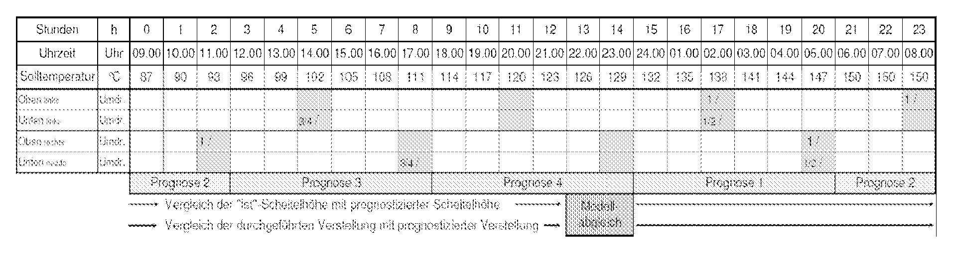
- the simulation program can also be used to create a tabular planning overview with regard to the personnel responsible for checking the commissioning process and, in particular, for adjusting the clamping system, as the following table illustrates by way of example:
- FIG. 3 shows the time course of the temperature control curve 46 and the apex rise 48 of the arch 18.
- the temperature control curve 46 is basically before the beginning of transient operating state, in particular the commissioning of the thermal processing plant 100, fixed. However, it may be modified based on the numerical calculation. It serves as a reference variable for the operating personnel, after which the Auffilbrenner 14 are to be driven. Since the various areas of the thermal processing installation 100 heat up at different speeds and, in particular, the edge areas more slowly, the temperature differences are constantly detected during startup by evaluating the thermographic images of the cameras with temperature field visualization 24.
- the temperature control curve 46 has at different time intervals 50a, b, c, d different rates of temperature increases, which is due to the different thermal expansion of the different materials used in different temperature ranges.
- the peak increase is constantly controlled by making corrections in the form of lateral displacements of the standing anchor 32. Since these corrections take place up to several times per hour, the result is that shown in FIG. 3, which is discontinuous in comparison to the temperature-control curve 46.
- the described numerical model can predict the temporal course of the transient operating state on the basis of certain boundary conditions. It At any time a comparison with the real boundary conditions, ie the actual state, take place.
- the peak increase shown in Figure 3 the result of the predictive calculation, the real history or even a mixture of forecast and actual state. In the latter case, the course shown corresponds to the real course up to a certain time, while the further time course is the result of the predictive simulation.
Landscapes
- Engineering & Computer Science (AREA)
- Chemical & Material Sciences (AREA)
- Materials Engineering (AREA)
- Organic Chemistry (AREA)
- Mechanical Engineering (AREA)
- General Engineering & Computer Science (AREA)
- Investigating Or Analyzing Materials Using Thermal Means (AREA)
- Control Of Temperature (AREA)
Abstract
Description
- Für die Länge einer Ofenreise von Thermoprozessanlagen wie beispielsweise von Glasschmelzwannen sind nicht allein die Betriebsweise, der Bau und die Materialqualität ausschlaggebend. Die Inbetriebnahme oder "das Tempern" von Ofenbauteilen hat einen großen Einfluss auf die Standsicherheit und die Haltbarkeit von Industrieöfen und damit der Thermoprozessanlage.
- Beispielsweise kommt es beim Aufheizen einer Glasschmelzwanne auf ihre Betriebstemperatur aufgrund der temperaturbedingten Ausdehnung der Materialien zu Verformungen der Bauteile und zum Entstehen von Rissen und Fugen.
- Aufgabe der Erfindung ist es, ein Verfahren zur Kontrolle eines instationären Betriebszustandes in einer Thermoprozessanlage anzugeben, durch welches Schäden an den einzelnen Bauteilen der Anlage verringert oder ganz vermieden werden können. Es handelt sich dabei gleichzeitig um ein Verfahren zur Visualisierung und Prognostizierung des instationären Betriebszustands.
- Erfindungsgemäß wird diese Aufgabe mittels eines Verfahrens mit den im Anspruch 1 genannten Merkmalen gelöst. Folgende Verfahrensschritte sind vorgesehen:
- Aufheizen oder Abheizen der Thermoprozessanlage auf Grundlage einer zeitabhängigen Temperaturführungskurve T(t);
- Erfassen von Temperaturmesswerten TMW(t, r) an verschiedenen Positionen der Thermoprozessanlage;
- numerische Berechnung von Spannungen und Verformungen innerhalb mindestens eines Bauteils oder einer Bauteilgruppe der Thermoprozessanlage, wobei die numerische Berechnung zumindest auf Grundlage von geometrischen Parametern, von Materialwerten und auf Grundlage der erfassten Temperaturmesswerte TMW(t, r) erfolgt;
- Vornahme von Korrekturen auf Grundlage der numerischen Berechnung.
- Unter Korrekturen werden insbesondere alle Handlungen verstanden, welche den instationären Betriebszustand in seiner zeitlichen Entwicklung derart verändern, dass eine Schädigung oder mechanische Beeinträchtigung des Bauteils oder der Bauteilgruppe vermieden werden können. Ziel ist dabei eine schonende Behandlung des statischen Systems (z. B. Vermeidung von Fugenbildung, Minimierung der auftretenden Druckspannungen). Die Korrekturen können unterschiedlicher Natur sein. So kann auf Grundlage der numerischen Berechnung eine Korrektur in Form einer Modifikation der Temperaturführungskurve T(t) oder einer statischen Modifikation des Einspannsystems, welches einzelne Bauteile oder Bauteilgruppen statisch trägt oder stützt, erfolgen. Das Einspannsystem kann aus verschiedenen Elementen wie beispielsweise Widerlagern, Ankern, Druckbolzen, Zugbolzen, Auflageschienen, Querverbindern oder dergleichen bestehen.
- Durch das der numerischen Berechnung zugrundeliegende Simulationsmodell wird der typische Erstinbetriebnahmeverlauf in seiner Temperaturführung und der mechanischen Veränderung der einzelnen Bauteile einer Thermoprozessanlage abgebildet. In das Modell fließt auch der bisherige Kenntnisstand des Verhaltens von Hochtemperaturanlagen bei Inbetriebnahme ein, wie z. B. bezüglich des Materialverschleißes. Die numerische Berechnung findet im Voraus statt, so dass das mechanische Verhalten der Bauteile und der Temperaturverlauf schon zu einem späteren Zeitpunkt bekannt sind. Die Simulation begleitet somit den instationären Prozess und prognostiziert die Verformung der Ofenbauteile für einen folgenden Zeitabschnitt (beispielsweise für die folgenden 6, 12, 24 und 48 h), woraus eine Strategie für die Verstellung des Einspannsystems abgeleitet werden kann. Wenn der reale Prozess so verläuft wie berechnet, werden die vom Programm berechneten Korrekturen ausgeführt. Das Erstellen von verschiedenen Szenarien und Strategien des Prozesses unter verschiedenen zeitlichen Verläufen der Randbedingungen ist durch einfache Modifikation des Berechnungsprogramms möglich.
- Bevorzugt ist vorgesehen, dass im Rahmen der numerischen Berechnung Erwärmungs- und Dehnungsvorgänge im Bauteil oder in der Bauteilgruppe berücksichtigt werden. Die für die numerische Berechnung benötigten Materialwerte spiegeln das thermische Verhalten der benutzten Feuerfestmaterialen beim Aufheizen und bei Betriebstemperaturen in Hochtemperaturanlagen wider. Es handelt sich typischerweise um folgende physikalischen Größen:
- Dichte in kg/m
- Wärmeleitfähigkeit in W/(m*K)
- spez. Wärmekapazität in J/(kg*K)
- thermischer Längenausdehnungskoeffizient in 1/K
- E-Modul in N/M2.
- Bevorzugt erfolgt die numerische Berechnung mit Hilfe einer Finite-Elemente-Methode, welche für die Berechnung von Druckspannungen in Bauteilen und von Wärmeleitungsproblemen besonders geeignet ist. Außerdem ist bevorzugt, dass bei der numerischen Berechnung eine Angleichung an in der Thermoprozessanlage insbesondere durch Wegaufnehmer erfasste Positionsmesswerte erfolgt. Durch diesen Abgleich wird die Genauigkeit der Simulationsergebnisse erhöht.
- Vorzugsweise werden Temperaturdaten durch eine spezielle, visuelle und auf Thermografie beruhende Messtechnik geliefert. Daher ist vorgesehen, dass die Temperaturmesswerte T MW(t, r) durch ein thermografisches Verfahren, insbesondere durch den Einsatz einer oder mehrerer Kameras mit Temperaturfeldvisualisierung, erfasst werden.
- In weiterer bevorzugter Ausführungsform der Erfindung ist vorgesehen, dass die Thermoprozessanlage ein Gewölbe umfasst, deren Widerlager durch ein Ankersystem gestützt wird, und dass auf Grundlage der numerischen Berechnung eine Korrektur in Form einer Verschiebung des Ankersystems vorgenommen wird. Durch das Simulationsprogramm wird eine Strategie für die Verstellung der Widerlager- und Ankersysteme erstellt. Die Korrekturen werden zeitnah durchgeführt. Messwerte und numerische Randbedingungen werden ständig überwacht und verglichen, bei Abweichungen wird das Rechenmodell auf den "lst"-Zustand abgeglichen und präzisierte Prognosen für die nächste 24 h erstellt.
- Bevorzugt umfasst das Ankersystem Paare von vertikalen Stehankern, welche über das Gewölbe hinweg durch horizontale Zuganker verbunden sind, wobei die Widerlager des Gewölbes auf Widerlagerschienen angeordnet sind, welche mit den Stehankern verbunden oder an diesen befestigt sind.
- Die Erfindung wird nachfolgend in einem Ausführungsbeispiel anhand der zugehörigen Zeichnungen näher erläutert. Es zeigen:
- Figur 1
- eine Oberansicht einer Großraumglasschmelzwanne;
- Figur 2
- eine dreidimensionale Darstellung des Schmelzwannengewölbes und
- Figur 3
- den zeitlichen Verlauf einer Temperaturführungskurve sowie des Scheitelanstiegs des Schmelzwannengewölbes.
- Figur 1 zeigt eine Oberansicht einer insgesamt mit 100 bezeichneten Thermoprozessanlage, hier einer Großraumglasschmelzwanne. Sie umfasst einen Hauptprozessraum 10 und zwei Nebenprozessräume oder Regeneratoren 12. Das gesamte Ofensystem besteht aus Bauteilgruppen aus Feuerfestmaterial und einer sie umgebenden Stahlkonstruktion, welche das Ofensystem zusammenhält und deren Ausmaße bei der Inbetriebnahme der thermischen Ausdehnung der Bauteile angepasst werden müssen, da sie sich nicht mit der gleichen Geschwindigkeit wie diese ausdehnt. An den Seitenwänden des Hauptprozessraumes 10 sind Aufheizbrenner 14 angeordnet, durch welche auf Grundlage einer vorgegebenen, noch näher zu beschreibenden, Temperaturführungskurve die Temperatur im Hauptprozessraum 10 erhöht wird. Der Hauptprozessraum 10 weist ein Gewölbe 18 (vgl. Figur 2) auf, welches während der Inbetriebnahme der Thermoprozessanlage aufgrund der Temperaturerhöhung ansteigt. Durch Wegaufnehmer 20, welche entlang einer Längsachse 16 der Glasschmelzwanne positioniert sind, wird der Anstieg des Gewölbes 18 gemessen. Optional kann der Anstieg an weiteren Messpunkten 22 manuell erfasst werden.
- Die Temperatur im Hauptprozessraum 10 wird an verschiedenen Positionen ständig überwacht. Die so ermittelte Funktion der Zeit und des Ortes wird als Input für ein noch zu beschreibendes numerisches Modell verwendet. Vorzugsweise wird dabei die Temperatur auf der Innenoberfläche verschiedener Bauteile oder Bauteilgruppen ermittelt. Aufgrund der auftretenden Temperaturabweichungen zwischen verschiedenen Bereichen des Hauptprozessraums 10 ist es bevorzugt, das Temperaturfeld durch ein thermographisches Verfahren zu visualisieren und somit eine zwei- oder dreidimensionale Darstellung der Temperaturverteilung zu ermitteln. Dazu werden an den Seitenwänden des Hauptprozessraumes 10 Kameras mit Temperaturfeldvisualisierung 24 angeordnet, welche ständig Temperaturfeldverteilungsbilder erzeugen.
- Figur 2 zeigt eine perspektivische Darstellung eines Abschnitts des Hauptprozessraumes 10. Ein Bassin 26, Stirnwände 28 und das darauf angeordnete Gewölbe 18 bestehen aus Feuerfestmaterial. Umgeben wird dieses System durch eine Stahlkonstruktion, bestehend aus einem Stahlfundament 30, Stehankern 32 und Zugankern 34. Das Gewölbe 18 drückt mit seinem Eigengewicht seine Widerlager 36 an Widerlagerschienen 38 an, welche senkrecht zu den Stehankern 32 verlaufen und an diesen befestigt sind. Das Gewölbe 18 besteht aus einem Gewölbestein 40 aus Silica und einer darauf angeordneten Wärmedämmungsschicht 42 aus leichtem Stein, welche das Gewölbe 18 isoliert. Zur Kontrolle, dass am Scheitel des Gewölbesteines 40 keine Schädigung in Form von Rissen oder Fugen auftritt sowie zur Positionierung der Wegaufnehmer 20, welche oberhalb des Gewölbes 18 angeordnet werden, ist in der Wärmedämmungsschicht 42 eine rillenförmige Aussparung 44 vorgesehen. Es kann auch eine größere Anzahl von Wärmedämmungsschichten übereinander angeordnet sein.
- Während der Inbetriebnahme der Glasschmelzwanne 100 kommt es durch die Temperaturfeldänderung zur Dehnung der Bauteile begleitet von einem Scheitelanstieg des Gewölbes 18 und einer Verstellung des Ankersystems 32, 34 und der Widerlager 36, 38. Bei einem zu großen oder zu schnellen Anstieg des Gewölbes 18 besteht die Gefahr der Entstehung zu hoher Spannungen oder der Entstehung von Rissen und Fugen. Dies wird dadurch verhindert, dass die Stehanker 32 seitlich verschoben werden (in Pfeilrichtung, vgl. Figur 2). Durch diese seitliche Verschiebung der Stehanker 32 kommt es zu einer Senkung des Gewölbes 18, der Schließung etwaiger Fugen und dem Abbau von Materialspannungen. Die seitliche Verschiebung der Stehanker 32 muss an ihren beiden Enden erfolgen (vgl. Position der Pfeile in Figur 2). An einem dem Bassin 26 gegenüberliegenden Ende werden die Zuganker 34 durch einen nicht dargestellten Schraubmechanismus verlängert, wodurch die Stehanker 32 nach außen gedrückt werden. Ein ähnlicher Mechanismus wird an der dem Bassin 26 zugewandten Seite angewandt. Die durch die seitliche Verschiebung der Stehanker 32 gegebenen Korrekturen erfolgen fortlaufend während der Inbetriebnahme der Thermoprozessanlage 100, beispielsweise im Stundenrhythmus. Die detaillierten Entscheidungen über Zeitpunkt und Größe der Korrekturen erfolgen auf Grundlage einer im Folgenden beschriebenen numerischen Berechnung.
- Eine numerische Berechnung von Spannungen und Verformungen innerhalb einzelner Bauteile oder Bauteilgruppen der Thermoprozessanlage 100 erfolgt dadurch, dass ein numerisches Modell für die Gesamtheit der Bauteile einschließlich Gewölbe 18 und dem u.a. aus dem Ankersystem 32, 34 und den Widerlagerschienen 38 bestehendem Einspannsystem erstellt wird. In dieses numerische Modell gehen geometrische Parameter ein, das heißt Informationen über die räumliche Position und Form der einzelnen Bauteile. Außerdem sind relevante Materialwerte für die einzelnen Komponenten des Gewölbes 18 und des Einspannsystems Eingangswerte im numerischen Modell. Die Materialdaten der verwendeten Feuerfestmaterialien sind bereits im Vorhinein bekannt oder werden durch Probennahme und Bestimmung der Eigenschaften im Labor ermittelt. Weiterhin gehen in das numerische Modell auch eine noch zu beschreibende Temperaturführungskurve 46, die seitliche Verschiebung der Stehanker 32, dargestellt als Funktion der Position in Abhängigkeit von der Zeit, sowie die ebenfalls als Funktion der Zeit vorliegenden Informationen über die Temperaturwerte in verschiedenen Punkten oder verschiedenen Bereichen des Hauptprozessraums 10, welche in Form der durch die Kameras mit Temperaturfeldvisualisierung 24 erfassten thermographischen Aufnahmen bestehen, ein. Schließlich fließen auch Informationen über den Gewölbeanstieg, welche durch die Wegaufnehmer 20 erfasst werden, in das Modell ein. Durch das numerische Modell wird das mechanische und thermische Verhalten des Bassins 26, der Stirnwände 28, des Gewölbes 18 sowie des umgebenden Einspannsystems 30, 32, 34, 36 im Voraus berechnet. Dazu wird die zeitliche Entwicklung der instationären Temperaturfelder in den verschiedenen Bauteilgruppen sowie der darin auftretenden Spannungen, Kräfte und Verformungen simuliert. Es erfolgt ein ständiger Abgleich der Randbedingungen der Simulation mit erfassten Betriebzuständen bei der realen Inbetriebnahme der Thermoprozessanlage 100. Die an der Anlage erfassten Messwerte (bezüglich Position der Stehanker 32, des Gewölbes 18 sowie der Temperatur) werden dem Simulationsprogramm in periodischen Abständen übermittelt. Dadurch erfolgt eine ständige Angleichung des numerischen Modells an den Ist-Zustand.
- Für eine definierte Temperaturführungskurve wird vorausschauend eine Verstellstrategie für das Gewölbe 18 simuliert. Alternativ können dem numerischen Modell auch verschiedene, optionale zeitliche Entwicklungen der Temperaturführungskurve 46 zugrunde gelegt werden, und dem Bedienpersonal kann die Möglichkeit gegeben werden, aus den sich ergebenden, verschiedenen zeitlichen Verläufen eine geeignete Strategie auszuwählen. Das numerische Simulationsprogramm sagt voraus, zu welchem Zeitpunkt eine wie geartete Korrektur erfolgen soll. Beispielsweise könnte das Programm empfehlen, fünf Stunden nach dem aktuellen Zeitpunkt eine seitliche Verschiebung der Stehanker 32 in Höhe von 5 mm vorzunehmen. Das Programm kann weiterhin voraussagen, dass durch die Vornahme dieser Handlung das Auftreten einer Fuge verhindert werden kann.
- Das Simulationsprogramm kann derart angeglichen werden, dass die vom Programm errechneten Strategien bestimmte Kriterien erfüllen. So kann diejenige Strategie gesucht werden, bei welcher der zeitliche Anstieg des Gewölbes 18 möglichst konstant ist, oder bei welcher Spannungen innerhalb eines bestimmten Bauteiles möglichst konstant gehalten werden. Schon vor Inbetriebnahme der Thermoprozessanlage 100 können solche Strategien durch das gleiche numerische Modell berechnet werden, welches Bestandteil des erfindungsgemäßen Verfahrens ist. Der Simulation der zeitlichen Entwicklung des Inbetriebnahmeprozesses sind grundsätzlich nur durch die erforderliche Genauigkeit Grenzen bezüglich des simulierten Zeitraums gesetzt. Typischer Weise wird die Entwicklung der Verformungen, Spannungen und Temperaturverläufe für die folgenden 6, 12, 24 und 48 Stunden im Voraus berechnet. Schließlich empfiehlt das Simulationsprogramm Handlungen, welche die Schädigung der Bauteile verhindern, wenn das Programm das Auftreten bestimmter Ereignisse prognostiziert, z. B. wenn die Spannung in einem bestimmten Bereich oder wenn die Tiefe eines entstehenden Risses bestimmte Grenzwerte zu überschreiten drohen.
- Durch das Simulationsprogramm kann ebenfalls eine tabellarische Planungsübersicht bezüglich des für die Kontrolle des Inbetriebnahmeprozesses und insbesondere für die Verstellung des Einspannsystems verantwortlichen Personals erstellt werden, wie folgende Tabelle beispielhaft veranschaulicht:
- Figur 3 zeigt den zeitlichen Verlauf der Temperaturführungskurve 46 und des Scheitelanstiegs 48 des Gewölbes 18. Die Temperaturführungskurve 46 steht grundsätzlich vor Beginn des instationären Betriebszustandes, insbesondere der Inbetriebnahme der Thermoprozessanlage 100, fest. Sie wird allerdings auf Grundlage der numerischen Berechnung gegebenenfalls modifiziert. Sie dient als Führungsgröße für das Bedienpersonal, nach welcher die Aufheizbrenner 14 gefahren werden sollen. Da sich die verschiedenen Bereiche der Thermoprozessanlage 100 unterschiedlich schnell und insbesondere die Randbereiche langsamer aufheizen, werden während der Inbetriebnahme die Temperaturunterschiede ständig festgestellt, indem die thermografischen Aufnahmen der Kameras mit Temperaturfeldvisualisierung 24 ausgewertet werden. Die Temperaturführungskurve 46 weist in ihren verschiedenen Zeitabschnitten 50a, b, c, d verschiedene Raten der Temperaturerhöhungen auf, was durch die unterschiedliche thermische Dehnung der verschiedenen benutzten Materialien in unterschiedlichen Temperaturbereichen bedingt ist. Der Scheitelanstieg wird ständig dadurch kontrolliert, dass Korrekturen in Form von seitlichen Verschiebungen der Steh anker 32 vorgenommen werden. Da diese Korrekturen bis zu mehrmals stündlich erfolgen, ergibt sich der in Figur 3 dargestellte, im Vergleich zur Temperaturführungskurve 46 diskontinuierliche, Verlauf. Das beschriebene numerische Modell vermag auf Grundlage bestimmter Randbedingungen den zeitlichen Verlauf des instationären Betriebzustandes zu prognostizieren. Es kann jederzeit ein Abgleich mit den realen Randbedingungen, also dem Ist-Zustand, erfolgen. Somit kann der in Figur 3 dargestellte Scheitelanstieg das Ergebnis der prognostizierenden Berechnung, der reale Verlauf oder auch eine Mischung aus Prognose und Ist-Zustand sein. Im letzteren Fall entspricht der dargestellte Verlauf bis zu einem bestimmten Zeitpunkt dem realen Verlauf, während der weitere zeitliche Verlauf Ergebnis der vorausschauenden Simulation ist.
-
- 10
- Hauptprozessraum
- 12
- Nebenprozessräume, Regeneratoren
- 14
- Aufheizbrenner
- 16
- Längsachse
- 18
- Gewölbe
- 20
- Wegaufnehmer
- 22
- Messpunkte
- 24
- Kamera mit Temperaturfeldvisualisierung
- 26
- Bassin
- 28
- Stirnwände
- 30
- Stahlfundament
- 32
- Stehanker
- 34
- Zuganker
- 36
- Widerlager
- 38
- Widerlagerschienen
- 40
- Gewölbestein
- 42
- Wärmedämmung, Wärmedämmungsschicht
- 44
- Aussparung
- 46
- Temperaturführungskurve
- 48
- Scheitelanstieg
- 50a, b, c, d
- Zeitabschnitte
- 100
- Thermoprozessanlage
Claims (9)
- Verfahren zur Kontrolle eines instationären Betriebszustandes in einer Thermoprozessanlage (100), gekennzeichnet durch folgende Verfahrensschritte:- Aufheizen oder Abheizen der Thermoprozessanlage (100) auf Grundlage einer zeitabhängigen Temperaturführungskurve T(t) (46);- Erfassen von Temperaturmesswerten T MW(t, r) an verschiedenen Positionen der Thermoprozessanlage (100);- numerische Berechnung von Spannungen und Verformungen innerhalb mindestens eines Bauteils oder einer Bauteilgruppe der Thermoprozessanlage (100), wobei die numerische Berechnung zumindest auf Grundlage von geometrischen Parametern, von Materialwerten und auf Grundlage der erfassten Temperaturmesswerte T MW(t, r) erfolgt;- Vornahme von Korrekturen auf Grundlage der numerischen Berechnung.
- Verfahren nach Anspruch 1, dadurch gekennzeichnet, dass auf Grundlage der numerischen Berechnung eine Korrektur der Temperaturführungskurve T(t) (46) vorgenommen wird.
- Verfahren nach Anspruch 1 oder 2, dadurch gekennzeichnet, das s die Thermoprozessanlage (100) ein Einspannsystem umfasst, welches mindestens ein Bauteil oder eine Bauteilgruppe statisch trägt, stützt oder dergleichen, und dass auf Grundlage der numerischen Berechnung eine Korrektur in Form einer statischen Modifikation des Einspannsystems vorgenommen wird.
- Verfahren nach einem der vorangehenden Ansprüche, dadurch gekennzeichnet, dass im Rahmen der numerischen Berechnung Erwärmungs- und Dehnungsvorgänge im Bauteil oder in der Bauteilgruppe berücksichtigt werden.
- Verfahren nach einem der vorangehenden Ansprüche, dadurch gekennzeichnet, dass die numerische Berechnung mithilfe einer Finite-Elemente-Methode erfolgt.
- Verfahren nach einem der vorangehenden Ansprüche, dadurch gekennzeichnet, dass bei der numerische Berechnung eine Angleichung an in der Thermoprozessanlage (100) insbesondere durch Wegaufnehmer (20) erfasste Positionsmesswerte erfolgt.
- Verfahren nach einem der vorangehenden Ansprüche, dadurch gekennzeichnet, dass die Temperaturmesswerte TMW(t, r) durch ein thermografisches Verfahren, insbesondere durch den Einsatz einer oder mehrerer Kameras mit Temperaturfeldvisualisierung (24), erfasst werden.
- Verfahren nach einem der Ansprüche 3 - 8, dadurch gekennzeichnet, dass die Thermoprozessanlage (100) ein Gewölbe umfasst, deren Widerlager (36) durch ein Ankersystem gestützt wird, und dass auf Grundlage der numerischen Berechnung eine Korrektur in Form einer Verschiebung des Ankersystems vorgenommen wird.
- Verfahren nach Anspruch 8, dadurch gekennzeichnet, dass das Ankersystem Paare von vertikalen Stehankern (32) umfasst, welche über das Gewölbe hinweg von horizontalen Zugankern (34) verbunden sind, und dass die Widerlager (36) des Gewölbes auf Widerlagerschienen (38) angeordnet sind, welche mit den Stehankern (32) verbunden oder an diesen befestigt sind.
Applications Claiming Priority (1)
| Application Number | Priority Date | Filing Date | Title |
|---|---|---|---|
| DE102006020092 | 2006-04-26 |
Publications (2)
| Publication Number | Publication Date |
|---|---|
| EP1849752A1 true EP1849752A1 (de) | 2007-10-31 |
| EP1849752B1 EP1849752B1 (de) | 2014-03-12 |
Family
ID=38282870
Family Applications (1)
| Application Number | Title | Priority Date | Filing Date |
|---|---|---|---|
| EP20070107065 Not-in-force EP1849752B1 (de) | 2006-04-26 | 2007-04-26 | Verfahren zur Kontrolle eines instationären Betriebszustandes in einer Thermoprozessanlage |
Country Status (1)
| Country | Link |
|---|---|
| EP (1) | EP1849752B1 (de) |
Cited By (1)
| Publication number | Priority date | Publication date | Assignee | Title |
|---|---|---|---|---|
| WO2009115087A1 (de) * | 2008-03-20 | 2009-09-24 | Uwe Geib | Verfahren zur optimierung einer ofenreise. |
-
2007
- 2007-04-26 EP EP20070107065 patent/EP1849752B1/de not_active Not-in-force
Non-Patent Citations (5)
| Title |
|---|
| "ATTREMPAGE D'UN FOUR DE VERRE/GLASS FURNACE HEATING", VERRE, INSTITUT DU VERRE, PARIS, FR, vol. 8, no. 3, June 2002 (2002-06-01), pages 28 - 31, XP001123092, ISSN: 0984-7979 * |
| HÜTTENTECHNISCHE VEREINIGUNG DER DEUTSCHEN GLASINDUSTRIE: "HVG-Fortbildungskurse 2005 Glasschmelzofenbau Feuerfeste Werkstoffe und konstruktive Merkmale", 2005, VERLAG DER DEUTSCHEN GLASTECHNISCHEN GESELLSCHAFT, OFFENBACH/MAIN, XP002447837 * |
| TOOLEY, F.V.: "The Handbook of Glass Manufacture", 1984, ASHLEE PUBLISHING CO., INC., NEW YORK, XP002447838, 1 * |
| TRIBOLLET J-C ET AL: "HOW STRESSES DEVELOP DURNG HEATING UP OF AZS FUSED-CAST BLOCKS", GLASS INDUSTRY, GLASS INDUSTRY MAGAZINE. NEW YORK, US, vol. 76, no. 11, 10 October 1995 (1995-10-10), pages 26,29 - 32, XP000535683, ISSN: 0017-1026 * |
| WERSCHY MATTHIAS ET AL: "Visual depiction of the structural condition and temperature fields in the combustion chamber of glass melting furnaces", GAS, WAERME INTERNATIONAL, VULKAN VERLAG, ESSEN, DE, vol. 49, no. 11, November 2000 (2000-11-01), pages 567 - 571, XP009087472, ISSN: 0020-9384 * |
Cited By (2)
| Publication number | Priority date | Publication date | Assignee | Title |
|---|---|---|---|---|
| WO2009115087A1 (de) * | 2008-03-20 | 2009-09-24 | Uwe Geib | Verfahren zur optimierung einer ofenreise. |
| EA018851B1 (ru) * | 2008-03-20 | 2013-11-29 | Уве Гайб | Способ продления кампании плавильной печи и устройство для его осуществления |
Also Published As
| Publication number | Publication date |
|---|---|
| EP1849752B1 (de) | 2014-03-12 |
Similar Documents
| Publication | Publication Date | Title |
|---|---|---|
| EP1444059B1 (de) | Steuerverfahren für eine einer kühlstrecke vorgeordnete fertigstrasse zum walzen von metall-warmband | |
| DE10122112B4 (de) | Vorrichtung zur Messung von Wärmespannungen von Betonbauten | |
| EP2262742B1 (de) | Verfahren zur optimierung einer ofenreise. | |
| EP3793926B1 (de) | Verfahren und vorrichtung zum überwachen eines zustands einer personentransportanlage unter verwendung eines digitalen doppelgängers | |
| EP2603333B1 (de) | Echtzeit-ermittlungsverfahren für temperatur und geometrie eines metall-warmbandes in einer fertigstrasse | |
| DE102011116806B4 (de) | Verfahren zur Herstellung eines zylinderförmigen Bauteils aus Glas durch Elongieren | |
| EP2607892B1 (de) | Verfahren zur Bestimmung von Wärme- und Temperaturleitfähigkeiten einer Messprobe | |
| DE3335710C2 (de) | Verfahren zum Anbohren der Deckziegel eines Koksofens | |
| EP1849752B1 (de) | Verfahren zur Kontrolle eines instationären Betriebszustandes in einer Thermoprozessanlage | |
| WO2020094778A1 (de) | Verfahren und system zur dynamischen visualisierung von strukturverzerrungen in einer stranggiessanlage | |
| EP1835279A2 (de) | Verfahren und Messvorrichtung zur Ermittlung der Wärmeleitfähigkeit des Feuerfestmaterials einer Ofenauskleidung | |
| EP3533533B1 (de) | Vorrichtung und ein verfahren zum prüfen einer funktionsfähigkeit von an einer giessform verteilt angeordneten temperatursensoren | |
| DE19853785C5 (de) | Verfahren und Meßanordnung zum Bestimmen von Veränderungen des Betriebszustandes von feuerfesten Baustoffen an Glasschmelze führenden Behältern | |
| RU2389987C1 (ru) | Способ измерения усилия в рабочей стержневой арматуре железобетонного сооружения | |
| DE102017113358B4 (de) | Feuerverzinkungsvorrichtung sowie Feuerverzinkungsverfahren | |
| Nguyen et al. | The effect of temperature variations on the camber of precast, prestressed concrete girders | |
| DE19744815C1 (de) | Verfahren zur Materialflußbestimmung und -steuerung von stranggegossenen Brammen | |
| Abid et al. | Experimental records based-simplified modeling of mean temperatures of steel beams in open environment | |
| DE2241268C3 (de) | Verfahren zum Verlängern der ununterbrochenen Standzeit von Ofengewölben und Vorrichtung zum Durchführen dieses Verfahrens | |
| EP2718041A1 (de) | Strangführungssegment einer strangführung einer stranggiessanlage und verfahren zum betreiben eines strangführungssegments | |
| DE102006009447B4 (de) | Verfahren zur Diagnostik von Tragwerken in baulichen Anlagen | |
| DE2345255C3 (de) | Vorrichtung zur Durchführung von Kontroll· und Wartungsarbeiten an einer Gießpfanne | |
| DE102006060695B4 (de) | Verfahren zur Herstellung von zwei- oder mehrfeldrigen Stahlverbundbrücken | |
| DE19853829B4 (de) | Temperaturunabhängige Herstellung von exakten Festen Fahrbahnen des Typs Rheda oder verwandter Typen | |
| Mussa et al. | Open Field Temperature and Strain Records of a Concrete-Steel Composite Beam |
Legal Events
| Date | Code | Title | Description |
|---|---|---|---|
| PUAI | Public reference made under article 153(3) epc to a published international application that has entered the european phase |
Free format text: ORIGINAL CODE: 0009012 |
|
| AK | Designated contracting states |
Kind code of ref document: A1 Designated state(s): AT BE BG CH CY CZ DE DK EE ES FI FR GB GR HU IE IS IT LI LT LU LV MC MT NL PL PT RO SE SI SK TR |
|
| AX | Request for extension of the european patent |
Extension state: AL BA HR MK YU |
|
| 17P | Request for examination filed |
Effective date: 20080430 |
|
| AKX | Designation fees paid |
Designated state(s): AT BE BG CH CY CZ DE DK EE ES FI FR GB GR HU IE IS IT LI LT LU LV MC MT NL PL PT RO SE SI SK TR |
|
| 17Q | First examination report despatched |
Effective date: 20101013 |
|
| GRAP | Despatch of communication of intention to grant a patent |
Free format text: ORIGINAL CODE: EPIDOSNIGR1 |
|
| INTG | Intention to grant announced |
Effective date: 20131128 |
|
| GRAS | Grant fee paid |
Free format text: ORIGINAL CODE: EPIDOSNIGR3 |
|
| GRAA | (expected) grant |
Free format text: ORIGINAL CODE: 0009210 |
|
| AK | Designated contracting states |
Kind code of ref document: B1 Designated state(s): AT BE BG CH CY CZ DE DK EE ES FI FR GB GR HU IE IS IT LI LT LU LV MC MT NL PL PT RO SE SI SK TR |
|
| REG | Reference to a national code |
Ref country code: GB Ref legal event code: FG4D Free format text: NOT ENGLISH |
|
| RIN1 | Information on inventor provided before grant (corrected) |
Inventor name: DR. PFITZNER, NORBERT Inventor name: FRANKE, MATTHIAS Inventor name: PROF. DR. WALTER, GERD |
|
| REG | Reference to a national code |
Ref country code: CH Ref legal event code: EP |
|
| REG | Reference to a national code |
Ref country code: AT Ref legal event code: REF Ref document number: 656180 Country of ref document: AT Kind code of ref document: T Effective date: 20140315 |
|
| REG | Reference to a national code |
Ref country code: IE Ref legal event code: FG4D Free format text: LANGUAGE OF EP DOCUMENT: GERMAN |
|
| RIN2 | Information on inventor provided after grant (corrected) |
Inventor name: FRANKE, MATTHIAS Inventor name: PROF. DR. WALTER, GERD Inventor name: DR. PFITZNER, NORBERT |
|
| REG | Reference to a national code |
Ref country code: DE Ref legal event code: R096 Ref document number: 502007012845 Country of ref document: DE Effective date: 20140424 |
|
| REG | Reference to a national code |
Ref country code: NL Ref legal event code: VDEP Effective date: 20140312 |
|
| PG25 | Lapsed in a contracting state [announced via postgrant information from national office to epo] |
Ref country code: LT Free format text: LAPSE BECAUSE OF FAILURE TO SUBMIT A TRANSLATION OF THE DESCRIPTION OR TO PAY THE FEE WITHIN THE PRESCRIBED TIME-LIMIT Effective date: 20140312 |
|
| REG | Reference to a national code |
Ref country code: LT Ref legal event code: MG4D |
|
| PG25 | Lapsed in a contracting state [announced via postgrant information from national office to epo] |
Ref country code: SE Free format text: LAPSE BECAUSE OF FAILURE TO SUBMIT A TRANSLATION OF THE DESCRIPTION OR TO PAY THE FEE WITHIN THE PRESCRIBED TIME-LIMIT Effective date: 20140312 Ref country code: CY Free format text: LAPSE BECAUSE OF FAILURE TO SUBMIT A TRANSLATION OF THE DESCRIPTION OR TO PAY THE FEE WITHIN THE PRESCRIBED TIME-LIMIT Effective date: 20140312 Ref country code: FI Free format text: LAPSE BECAUSE OF FAILURE TO SUBMIT A TRANSLATION OF THE DESCRIPTION OR TO PAY THE FEE WITHIN THE PRESCRIBED TIME-LIMIT Effective date: 20140312 |
|
| PG25 | Lapsed in a contracting state [announced via postgrant information from national office to epo] |
Ref country code: LV Free format text: LAPSE BECAUSE OF FAILURE TO SUBMIT A TRANSLATION OF THE DESCRIPTION OR TO PAY THE FEE WITHIN THE PRESCRIBED TIME-LIMIT Effective date: 20140312 |
|
| PG25 | Lapsed in a contracting state [announced via postgrant information from national office to epo] |
Ref country code: IS Free format text: LAPSE BECAUSE OF FAILURE TO SUBMIT A TRANSLATION OF THE DESCRIPTION OR TO PAY THE FEE WITHIN THE PRESCRIBED TIME-LIMIT Effective date: 20140712 Ref country code: EE Free format text: LAPSE BECAUSE OF FAILURE TO SUBMIT A TRANSLATION OF THE DESCRIPTION OR TO PAY THE FEE WITHIN THE PRESCRIBED TIME-LIMIT Effective date: 20140312 Ref country code: NL Free format text: LAPSE BECAUSE OF FAILURE TO SUBMIT A TRANSLATION OF THE DESCRIPTION OR TO PAY THE FEE WITHIN THE PRESCRIBED TIME-LIMIT Effective date: 20140312 Ref country code: RO Free format text: LAPSE BECAUSE OF FAILURE TO SUBMIT A TRANSLATION OF THE DESCRIPTION OR TO PAY THE FEE WITHIN THE PRESCRIBED TIME-LIMIT Effective date: 20140312 Ref country code: BG Free format text: LAPSE BECAUSE OF FAILURE TO SUBMIT A TRANSLATION OF THE DESCRIPTION OR TO PAY THE FEE WITHIN THE PRESCRIBED TIME-LIMIT Effective date: 20140612 Ref country code: CZ Free format text: LAPSE BECAUSE OF FAILURE TO SUBMIT A TRANSLATION OF THE DESCRIPTION OR TO PAY THE FEE WITHIN THE PRESCRIBED TIME-LIMIT Effective date: 20140312 |
|
| PG25 | Lapsed in a contracting state [announced via postgrant information from national office to epo] |
Ref country code: ES Free format text: LAPSE BECAUSE OF FAILURE TO SUBMIT A TRANSLATION OF THE DESCRIPTION OR TO PAY THE FEE WITHIN THE PRESCRIBED TIME-LIMIT Effective date: 20140312 Ref country code: PL Free format text: LAPSE BECAUSE OF FAILURE TO SUBMIT A TRANSLATION OF THE DESCRIPTION OR TO PAY THE FEE WITHIN THE PRESCRIBED TIME-LIMIT Effective date: 20140312 Ref country code: SK Free format text: LAPSE BECAUSE OF FAILURE TO SUBMIT A TRANSLATION OF THE DESCRIPTION OR TO PAY THE FEE WITHIN THE PRESCRIBED TIME-LIMIT Effective date: 20140312 Ref country code: MC Free format text: LAPSE BECAUSE OF FAILURE TO SUBMIT A TRANSLATION OF THE DESCRIPTION OR TO PAY THE FEE WITHIN THE PRESCRIBED TIME-LIMIT Effective date: 20140312 |
|
| REG | Reference to a national code |
Ref country code: CH Ref legal event code: PL |
|
| REG | Reference to a national code |
Ref country code: DE Ref legal event code: R097 Ref document number: 502007012845 Country of ref document: DE |
|
| PG25 | Lapsed in a contracting state [announced via postgrant information from national office to epo] |
Ref country code: PT Free format text: LAPSE BECAUSE OF FAILURE TO SUBMIT A TRANSLATION OF THE DESCRIPTION OR TO PAY THE FEE WITHIN THE PRESCRIBED TIME-LIMIT Effective date: 20140714 |
|
| PLBE | No opposition filed within time limit |
Free format text: ORIGINAL CODE: 0009261 |
|
| STAA | Information on the status of an ep patent application or granted ep patent |
Free format text: STATUS: NO OPPOSITION FILED WITHIN TIME LIMIT |
|
| REG | Reference to a national code |
Ref country code: IE Ref legal event code: MM4A |
|
| PG25 | Lapsed in a contracting state [announced via postgrant information from national office to epo] |
Ref country code: LI Free format text: LAPSE BECAUSE OF NON-PAYMENT OF DUE FEES Effective date: 20140430 Ref country code: DK Free format text: LAPSE BECAUSE OF FAILURE TO SUBMIT A TRANSLATION OF THE DESCRIPTION OR TO PAY THE FEE WITHIN THE PRESCRIBED TIME-LIMIT Effective date: 20140312 Ref country code: CH Free format text: LAPSE BECAUSE OF NON-PAYMENT OF DUE FEES Effective date: 20140430 |
|
| 26N | No opposition filed |
Effective date: 20141215 |
|
| REG | Reference to a national code |
Ref country code: DE Ref legal event code: R097 Ref document number: 502007012845 Country of ref document: DE Effective date: 20141215 |
|
| PG25 | Lapsed in a contracting state [announced via postgrant information from national office to epo] |
Ref country code: IT Free format text: LAPSE BECAUSE OF FAILURE TO SUBMIT A TRANSLATION OF THE DESCRIPTION OR TO PAY THE FEE WITHIN THE PRESCRIBED TIME-LIMIT Effective date: 20140312 |
|
| REG | Reference to a national code |
Ref country code: FR Ref legal event code: PLFP Year of fee payment: 9 |
|
| PG25 | Lapsed in a contracting state [announced via postgrant information from national office to epo] |
Ref country code: IE Free format text: LAPSE BECAUSE OF NON-PAYMENT OF DUE FEES Effective date: 20140426 |
|
| REG | Reference to a national code |
Ref country code: AT Ref legal event code: MM01 Ref document number: 656180 Country of ref document: AT Kind code of ref document: T Effective date: 20140426 |
|
| PG25 | Lapsed in a contracting state [announced via postgrant information from national office to epo] |
Ref country code: SI Free format text: LAPSE BECAUSE OF FAILURE TO SUBMIT A TRANSLATION OF THE DESCRIPTION OR TO PAY THE FEE WITHIN THE PRESCRIBED TIME-LIMIT Effective date: 20140312 |
|
| PG25 | Lapsed in a contracting state [announced via postgrant information from national office to epo] |
Ref country code: AT Free format text: LAPSE BECAUSE OF NON-PAYMENT OF DUE FEES Effective date: 20140426 |
|
| PG25 | Lapsed in a contracting state [announced via postgrant information from national office to epo] |
Ref country code: MT Free format text: LAPSE BECAUSE OF FAILURE TO SUBMIT A TRANSLATION OF THE DESCRIPTION OR TO PAY THE FEE WITHIN THE PRESCRIBED TIME-LIMIT Effective date: 20140312 |
|
| REG | Reference to a national code |
Ref country code: FR Ref legal event code: PLFP Year of fee payment: 10 |
|
| PG25 | Lapsed in a contracting state [announced via postgrant information from national office to epo] |
Ref country code: GR Free format text: LAPSE BECAUSE OF FAILURE TO SUBMIT A TRANSLATION OF THE DESCRIPTION OR TO PAY THE FEE WITHIN THE PRESCRIBED TIME-LIMIT Effective date: 20140613 |
|
| PG25 | Lapsed in a contracting state [announced via postgrant information from national office to epo] |
Ref country code: LU Free format text: LAPSE BECAUSE OF NON-PAYMENT OF DUE FEES Effective date: 20140426 Ref country code: HU Free format text: LAPSE BECAUSE OF FAILURE TO SUBMIT A TRANSLATION OF THE DESCRIPTION OR TO PAY THE FEE WITHIN THE PRESCRIBED TIME-LIMIT; INVALID AB INITIO Effective date: 20070426 Ref country code: TR Free format text: LAPSE BECAUSE OF FAILURE TO SUBMIT A TRANSLATION OF THE DESCRIPTION OR TO PAY THE FEE WITHIN THE PRESCRIBED TIME-LIMIT Effective date: 20140312 |
|
| PGFP | Annual fee paid to national office [announced via postgrant information from national office to epo] |
Ref country code: GB Payment date: 20160422 Year of fee payment: 10 Ref country code: DE Payment date: 20160428 Year of fee payment: 10 |
|
| PGFP | Annual fee paid to national office [announced via postgrant information from national office to epo] |
Ref country code: BE Payment date: 20160422 Year of fee payment: 10 Ref country code: FR Payment date: 20160422 Year of fee payment: 10 |
|
| REG | Reference to a national code |
Ref country code: DE Ref legal event code: R119 Ref document number: 502007012845 Country of ref document: DE |
|
| GBPC | Gb: european patent ceased through non-payment of renewal fee |
Effective date: 20170426 |
|
| REG | Reference to a national code |
Ref country code: FR Ref legal event code: ST Effective date: 20171229 |
|
| PG25 | Lapsed in a contracting state [announced via postgrant information from national office to epo] |
Ref country code: DE Free format text: LAPSE BECAUSE OF NON-PAYMENT OF DUE FEES Effective date: 20171103 Ref country code: FR Free format text: LAPSE BECAUSE OF NON-PAYMENT OF DUE FEES Effective date: 20170502 |
|
| PG25 | Lapsed in a contracting state [announced via postgrant information from national office to epo] |
Ref country code: GB Free format text: LAPSE BECAUSE OF NON-PAYMENT OF DUE FEES Effective date: 20170426 |
|
| REG | Reference to a national code |
Ref country code: BE Ref legal event code: MM Effective date: 20170430 |
|
| PG25 | Lapsed in a contracting state [announced via postgrant information from national office to epo] |
Ref country code: BE Free format text: LAPSE BECAUSE OF NON-PAYMENT OF DUE FEES Effective date: 20170430 |