EP1849739A1 - Elevator-use hoist machine and bearing replacing method for elevator-use hoist machine - Google Patents
Elevator-use hoist machine and bearing replacing method for elevator-use hoist machine Download PDFInfo
- Publication number
- EP1849739A1 EP1849739A1 EP06712786A EP06712786A EP1849739A1 EP 1849739 A1 EP1849739 A1 EP 1849739A1 EP 06712786 A EP06712786 A EP 06712786A EP 06712786 A EP06712786 A EP 06712786A EP 1849739 A1 EP1849739 A1 EP 1849739A1
- Authority
- EP
- European Patent Office
- Prior art keywords
- bearing
- housing
- rotor
- traction machine
- stationary shaft
- Prior art date
- Legal status (The legal status is an assumption and is not a legal conclusion. Google has not performed a legal analysis and makes no representation as to the accuracy of the status listed.)
- Withdrawn
Links
Images


Classifications
-
- B—PERFORMING OPERATIONS; TRANSPORTING
- B66—HOISTING; LIFTING; HAULING
- B66B—ELEVATORS; ESCALATORS OR MOVING WALKWAYS
- B66B11/00—Main component parts of lifts in, or associated with, buildings or other structures
- B66B11/04—Driving gear ; Details thereof, e.g. seals
- B66B11/043—Driving gear ; Details thereof, e.g. seals actuated by rotating motor; Details, e.g. ventilation
-
- B—PERFORMING OPERATIONS; TRANSPORTING
- B66—HOISTING; LIFTING; HAULING
- B66B—ELEVATORS; ESCALATORS OR MOVING WALKWAYS
- B66B11/00—Main component parts of lifts in, or associated with, buildings or other structures
- B66B11/04—Driving gear ; Details thereof, e.g. seals
- B66B11/08—Driving gear ; Details thereof, e.g. seals with hoisting rope or cable operated by frictional engagement with a winding drum or sheave
-
- B—PERFORMING OPERATIONS; TRANSPORTING
- B66—HOISTING; LIFTING; HAULING
- B66B—ELEVATORS; ESCALATORS OR MOVING WALKWAYS
- B66B11/00—Main component parts of lifts in, or associated with, buildings or other structures
- B66B11/04—Driving gear ; Details thereof, e.g. seals
- B66B11/043—Driving gear ; Details thereof, e.g. seals actuated by rotating motor; Details, e.g. ventilation
- B66B11/0438—Driving gear ; Details thereof, e.g. seals actuated by rotating motor; Details, e.g. ventilation with a gearless driving, e.g. integrated sheave, drum or winch in the stator or rotor of the cage motor
-
- B—PERFORMING OPERATIONS; TRANSPORTING
- B66—HOISTING; LIFTING; HAULING
- B66B—ELEVATORS; ESCALATORS OR MOVING WALKWAYS
- B66B7/00—Other common features of elevators
Definitions
- the present invention relates to traction machines for use in an elevator and methods of replacing bearing of the traction machines.
- Patent Document 1 because, from the housing side as viewed along the shaft, a rotor is fixed and, by demounting a mounting bed located in the direction opposite to the housing, the drive sheave, the shaft and the bearing are drawn out as one part, replacement is performed from both sides along the shaft, thereby requiring a wider replacement space on both side along the shaft.
- the present invention has been made to solve above-described problems, and an object of the invention is to obtain an elevator traction machine that enables replacement of a shaft to easily be performed unidirectionally in a machine-roomless elevator.
- the present invention comprises: a housing for fixing thereto a magnetic-circuit-constituting stator; a stationary shaft adapted to fit into a bearing, within the inner circular area of the bearing, and thereby to dispose the bearing to be coaxial with the stator axial center and being detachably fastened to the housing in a space provided in the area surrounding the center of the housing; a bearing boss adapted to fit with the circumference of the bearing as disposed on the stationary shaft, and able to pass through the space; and a magnetic-circuit-constituting rotor having a predetermined clearance from the stator, being detachably fastened to the bearing boss, located inside the rotor, and capable of being directly/indirectly fixed to the housing.
- the present invention also comprises; a housing for fixing thereto a magnetic-circuit-constituting stator; a stationary shaft adapted to fit into a bearing, within the inner circular area of the bearing, and thereby to dispose the bearing to be coaxial with the stator axial center, and being detachably fastened to the housing in a space provided in the area surrounding the center of the housing; a magnetic-circuit-constituting rotor through which the stationary shaft is able to pass, the rotor having a given clearance from the stator, and capable of being directly/indirectly fastened to the housing; and a bearing boss capable of fitting with the circumference of the bearing as disposed on the stationary shaft, and being detachably provided on the inner area of the rotor.
- the invention comprises steps of: directly/indirectly fastening the rotor to the housing; mounting and demounting the stationary shaft, the bearing and the bearing boss; inspecting/replacing the bearing; fastening the stationary shaft, the bearing and the bearing boss, and unfastening directly/indirectly the rotor having been fastened to the housing.
- the present invention has been implemented with such a constitution, and by a method according to the constitution, therefore, a traction machine for use in an elevator that enables a shaft to easily be replaced unidirectionally, can be achieved.
- “1” is a housing; “1a,” fixing holes; “1b,” fixing holes; “2,” a stator; “2a,” a core section; “2b,” coils; “3,” a stationary shaft; “3a,” fixing holes; “3b,” jack-up threaded screw holes ; “4,” a bearing; “5,” a bearing boss; “5a,” fixing holes; “5b,” a drive sheave; “6,” a rotor; “6a,” a drive sheave; “6b,” braking surfaces; “6c,” fixing holes; “6d,” threaded screw holes; “6e,” a circumference; “7,” a traction machine mount; “7a,” fixing holes; “7b,” threaded screw holes; “8,” a rotation detector; “9,” a rotary shaft; “10,” a cover; “11,” bolts; “12,” an alignment jig; “13,” bolts; “14,” bolts; “15,” bolts; “16,” bolts;
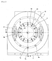
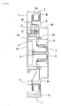
- Fig. 1 is a front elevation illustrating a traction machine of an elevator according to Embodiment 1 of the present invention, Fig. 2, a cross-sectional view taken along Line A-A in Fig. 1.
- a stator 2-part of the stationary element constituting an electric motor-is fixed inside the circumference of a housing 1, coils 2b-part of the stator-is wound around a core section 2a of the stator 2, and referring to Fig. 1, arranged coaxially with the circular-shaped housing 1 is a stationary shaft 3 that is fixed to the housing 1 with bolts 13.
- a bearing boss 5 is pivotally held via a bearing 4, coaxially with the stationary shaft 3, by the bearing 4. Fixing a rotor 6 by bolts 14, coaxially with the bearing boss 5 allows the rotor 6 to rotate coaxially with the stationary shaft 3.
- a rotary element forming part of the motor is constituted of the bearing boss 5 and the rotor 6, and the rotor 6 includes a drive sheave 6a that causes the hoist rope to travel, and a braking section 6b.
- the housing 1 is fixed to a traction machine mount 7 fixed at an installation position.
- the housing 1 and the traction machine mount 7 are separately configured, they may be integrally constituted.
- a rotation detector 8 that is provided coaxially with the center axis of the stationary shaft 3 and fixed to the stationary shaft 3, can detect rotation angles of the rotor 6 fixed to the bearing boss by engaging a rotary shaft 9 that is fixed to the bearing boss 5 and capable of rotating coaxially with the center axis of the stationary shaft 3.
- the rotation detector 8 is covered with a cover 10 so as not to be visually checked from the outside thereof.
- brakes 11 that oppose sliding surfaces 6b of the rotor 6 and have braking surfaces for acquiring braking force by abutment.
- the brakes 11 disengage abutment of the rotor braking surfaces 6b with the braking surfaces of the brakes 11, to neutralize the braking force as well as a controller of the traction machine, not shown, energizes the coils 2b of the stator 2, by a predetermined energizing pattern according to a value determined by the rotation detector 8, which thereby causes the rotor 6 to rotate in a predetermined direction.
- the rotation of the rotor 6 can cause an elevator car to travel in predetermined directions and to floors, via a hoist rope engaged with a drive sheave 6a of the rotor 6.
- the outline of the stationary shaft 3 is set to be larger than that of the bearing boss. Furthermore, the stationary shaft 3 is formed with fixing holes 3a that can be disposed substantially coaxially with the central axis of the bolts 14 so that the bolts 14 fastening the bearing boss 5 and the rotor 6 together is removable from the rotation detector 8 side, and the housing 1 and the rotor 6 are formed with fixing holes 1a and 6c that can each be disposed coaxially with them. Further, the inner circular portion to which the stationary shaft 3 of the housing 1 is fixed, is set to be smaller than that of the circumference of the rotor 6, and the traction machine mount 7 is formed with fixing holes 7a as well.
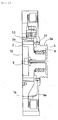
- Fig. 3 is a diagram for explaining a time of replacing shown in Fig. 2.
- the bolts 13 that fasten the housing 1 to the stationary shaft 3 are removed, by passing through the fixing holes 3a, the bolts 14 that fasten the rotor 6 to the bearing boss 5 are removed.
- the housing 1 and such the rotator 6 are fitted, according to the loose/free fit tolerance, into the stationary shaft 3 and the bearing boss 5, respectively, their positions remain fixed.
- the bolt 13 or 14 corresponding to those that are not aligned by fitting needs to be removed after the next step is performed.
- the next step is that an alignment jig 12 having holes that allow the rotor 6 to be made positioned coaxially with the fixing holes 1a, 3a and 7a, is made abut, on the side of the drive sheave 6a, on a surface perpendicular to the rotor's rotary shaft, and then, from the rotation detector 8 side, the alignment jig 12 is fastened with bolts 15 and 16 via the fixing holes 1a, 3a, and 7a. Tightening the bolts 15 fastens the rotor 6 to the alignment jig 12, and tightening the bolts 16 fastens the traction machine 7 to the alignment jig 12. In tightening the bolts, there is a need for precautions to be taken such that the rotation axis center of the rotor 6 will not deviate from a predetermined position.
- the final step is that after jack screws, not shown, has been passed through jack-up threaded screw holes 3b provided on the stationary shaft 3 shown in Fig. 1, a jack-up operation permits the stationary shaft 3, the bearing 4, and the bearing boss 5 to be removed.
- the bearing 4 is easy to demount if fitting the stationary shaft 3 into the bearing 4, and the bearing 4 into the bearing boss 5 are each made according to the loose/free fit tolerance.
- the bearing 4 can be replaced with the hoist rope being engaged with the drive sheave.
- This arrangement can eliminate a dangerous work such as shifting a load applied to the hoist rope 6, to another member. Elimination of the dangerous work can significantly reduce hours for replacing the bearing 4.
- a space required for the replacement may be as large as is needed for inserting the alignment jig 12, being only the space on the rotation detector 8 side. Therefore, the bearing 4 can be replaced substantially from one side, thereby requiring no extra replacment space.
- the traction machine for the elevator in which the bearing 4 can easily be replaced from one side can be achieved because the traction machine comprises the housing 1 for fastening thereto the magnetic-circuit-constituting stator 2 that generates electromagnetic force, the stationary shaft 3 adapted to fit into the bearing 4, within the inner circular area of the bearing 4, and thereby to dispose the bearing to be coaxial with the stator 2 axial center, and being detachably fastened to the housing 1 in a space provided in the area surrounding the center of the housing 1, the one-rotary-element-constituting bearing boss 5 adapted to fit with the circumference of the bearing as disposed on the stationary shaft, and able to pass through the space, and the magnetic-circuit-constituting rotor 6 having a predetermined clearance from the stator, being detachably fastened to the bearing boss 5 located inside the rotor, and capable of being directly/indirectly fastened to the housing 1.
- Embodiment 1 the case where replacing the bearing 4 is performed from the opposite side of the drive sheave 6a has been described.
- Embodiment 2 a case where such the bearing 4 is replaced from the side of the drive sheave 6a will be described.
- Fig. 4 is a cross-sectional view corresponding to Fig.2 of a traction machine of an elevator in Embodiment 2 of the present invention.
- portions that are not particularly indicated are the same as those in Embodiment 1, and in Fig. 4, the same symbols as those in Fig. 2 indicate the same or equivalent parts.
- Embodiment 1 A constitution differing from the traction machine in Embodiment 1 will be described as below.
- Embodiment 1 in order to allow the replacement to be performed from only the side of the rotation detector 8-the opposite side of the drive sheave 6a-such the fixing holes 3a for passing therethrough such the bolts 14 that fasten such the bearing boss 5 to such the rotor 6 have been formed.
- the bearing boss 5 in order to allow the replacement to be performed only from the side of the drive sheave 6a, instead of the fixing holes 3a, the bearing boss 5 is formed with fixing holes 5a for passing therethrough such the bolts 13 for fastening the housing 1 to such the stationary shaft 3.
- Fig. 5 is a diagram for explaining a time of replacing shown in Fig. 4.
- the bolts 14 that fasten the rotor 6 to the bearing boss 5 are first removed, by passing through the fixing holes 5 the bolts 14 that fasten the bearing boss 5 to the housing 1, the bolts 13 that fasten the housing 1 to the stationary shaft 3 are removed.
- the housing 1 and the rotator 6 are fitted, according to the loose/free fit tolerance, into the stationary shaft 3 and the bearing boss 5, respectively, thus their positions remain fixed.
- the bolt 13 or 14 corresponding to those that are not aligned by fitting needs to be removed after the next step is performed.
- the next step is that an alignment jig 17 having holes that allow [the rotor 6 and the stationary shaft 3] to be positioned coaxially with the threaded screw holes 6d and 7b, is abutted, from the side of the drive sheave 6a, a surface perpendicular to the rotor's rotary shaft, and then the alignment jig 17 is threadably fastened by passing, from the side of the drive sheave 6a, via fixing holes that are formed on the alignment jig 17, such the bolts 15 and the bolts 16 through the threaded screw holes 6d and 7b.
- the final step is, not shown, that after jack screws, not shown, have been passed through jack-up threaded screw holes corresponding to the jack-up threaded screw holes 3b in Embodiment 1, a jack-up operation is started, which allows the stationary shaft 3, the bearing 4, and the bearing boss 5 to be demounted.
- the bearing 4 is easy to demount if fitting the stationary shaft 3 into the bearing 4, and the bearing 4 into the bearing boss 5 are each made according to the loose/free fit tolerance.
- the bearing 4 can be replaced with the hoist rope being engaged with the drive sheave.
- This arrangement can eliminate a dangerous work such as shifting a load applied to the hoist rope 6, to another member. Elimination of the dangerous work can significantly reduce hours for replacing the bearing 4.
- a space needed for the replacement may be that needed for work only on the side of the drive sheave 6a, i.e., the bearing 4 can be replaced from one side, which therefore requires no extra replacing space.
- Embodiment 2 of the present invention comprises the housing 1 for fastening thereto the magnetic-circuit-constituting stator 2 that generates electromagnetic force, the stationary shaft 3 adapted to fit into a bearing 4, within an inner circular area of the bearing 4, and thereby to dispose the bearing to be coaxial with the stator 2 axial center, and being detachably fastened to the housing 1 in a space provided in an area surrounding the center of the housing 1, the magnetic-circuit-constituting rotor 6 having a predetermined clearance from the stator, being detachably fastened to the bearing boss 5, located on the inside of the rotor, and being capable of being directly/indirectly fastened to the housing 1, and the bearing boss 5 adapted to fit with the circumference of the bearing as disposed on the stationary shaft, and able to pass through the space, then effects that are the same as those in Embodiment 1 can be acquired.
- Embodiment 2 during the replacement of the bearing 4, there is no need for the alignment jig 12 to be positioned on the opposite side of a place where work is to be performed.
- a workspace completely on only the side of the drive sheave 6a enables the work to be performed.
- the alignment 17 is disposed on the side of the drive sheave 6a, therefore, replacement efficiency can be improved accordingly.
- Embodiment 1 and 2 have utilized the alignment jigs 12 and 17, respectively, for the replacement of the bearing 4, whereas in Embodiment 3, a case where replacement of the bearing 4 can be performed without employing alignment jigs 12 and 17 will be described.
- Fig. 6 is a cross-sectional view corresponding to Fig.2 of a traction machine of an elevator in Embodiment 3 of the present invention.
- portions that are not particularly indicated are the same as those in Embodiment 1, and in Fig. 6, the same symbols as those in Fig. 2 indicate the same or equivalent parts.
- Embodiment 2 A constitution differing from the traction machine in Embodiment 1 will be described as below.
- the traction machine in Embodiment 2 is formed, in place of the fixing holes 1a that allow the head portion of the bolts 15 in Embodiment 1 to pass therethrough, with fixing holes 1b that allow only the threaded portion of the bolts 15 to pass therethrough, as well as is formed, in place of the fixing holes 6c that has allowed the threaded portion of the bolts 15 to pass, with the threaded screw hole 6e that allow the bolts 15 passed from the opposite side of the drive sheave 6a to be threaded thereinto.
- the bearing 4 is easy to demount if fitting the stationary shaft 3 into the bearing 4, and the bearing 4 into the bearing boss 5 are each made according to the loose/free fit tolerance.
- the bearing 4 can be replaced with the hoist rope being engaged with the drive sheave.
- This arrangement can eliminate a dangerous work such as shifting a load applied to the hoist rope 6, to another member. Elimination of the dangerous work can significantly reduce hours for replacing the bearing 4.
- a space required for the replacement may be only that on the opposite side of the drive sheave 6a, i.e., the replacement of the bearing 4 can be performed from one side, thereby requiring no extra replacing space.
- Embodiment 3 of the present invention can acquire effects that are the same as those in Embodiment 1.
- the bearing 4 can be replaced without a need for the alignment jigs employed in Embodiment 1 and 2.
- Embodiment 4 a case where more accurate work in comparison with that in Embodiment 3 can achieve the replacement of the bearing 4 will be described.
- Fig. 7 is a cross-sectional view corresponding to Fig.2 of a traction machine for an elevator in Embodiment 4 of the present invention;
- portions that are not particularly indicated are the same as those in Embodiment 1, and in Fig. 4, the same symbols as those in Fig.2 indicate the same or the equivalent ones in Fig. 4.
- Fig. 8 is a detailed diagram of Section "B" in Fig. 7;
- the housing 1 is provided with cylindrical fitting surfaces 1c that allow the housing 1 to be fitted into the circumference 6f of the rotor 6.
- the replacement of a bearing 4 will be described as below.
- the first step is the same as that described in Embodiment 3.
- the next step is that after jack screws, not shown, have been threaded into the jack-up threaded screw holes provided on the stationary shaft 3, a jack-up operation is started, which moves by a length of D1 the stationary shaft 3, the bearing 4 and the bearing boss 5, making the rotor 6 abut the housing 1 while the circumference 6e of the rotor 6, and the fitting surfaces 1c of the housing 1 are being fitted to each other. From the opposite side of the drive sheave 6a, by passing the threaded portion of the bolts 15 through the fixing holes 1b, the housing 1 and the rotor 6 are fastened together. In tightening the bolts, there is a need for precautions to be taken such that the rotation axis center of the rotor 6 will not deviate from a predetermined position.
- the final step also enables the stationary shaft 3, the bearing 4, and the bearing boss 5 to be demounted by the work that is the same as in Embodiment 3.
- Embodiment 4 of the present invention can acquire effects that are the same as those in Embodiment 3.
- Embodiment 5 in the case where the traction machine in Embodiment 3 is disposed on the ceiling of the hoistway, a bearing-4-replacement-method will be described by which any of the stationary shaft 3, the bearing 4 and the bearing boss 5 can be protected from falling during their replacement.
- Fig. 9 is a cross-sectional view when a bearing 4 of a traction machine of an elevator corresponding to Fig. 2 in Embodiment 5 of the present invention is being replaced.
- portions that are not particularly indicated are the same as those in Embodiment 3, and in Fig. 9, the same symbols as those in Fig. 7 indicate the same or equivalent parts.
- the traction machine in Embodiment 5 has the same constitution as the traction machine in Embodiment 3.
- the bolts 13 that fasten the housing 1 to the stationary shaft 3 are removed, and next, by starting a jack-up operation after jack screws have been threaded into the jack-up threaded screw holes 3b provided on the stationary shaft 3, then the stationary shaft 3, the bearing 4, and the bearing boss 5 are shifted by dimension of D1, so that the rotor 6 abuts the housing 1.
- the housing 1 and the rotator 6 are fitted, according to the loose/free fit tolerance, into the stationary shaft 3 and the bearing boss 5, respectively, thus their positions remain fixed.
- a jack-up operation allows the stationary shaft 3, the bearing 4 and the bearing boss 5 to be demounted, when the thread studs 18 and the nuts 19 permit the stationary shaft 3, the bearing 4 and the bearing boss 5 to safely be demounted without letting them fall.
- the bearing 4 is easy to demount if fitting the stationary shaft 3 into the bearing 4, and the bearing 4 into the bearing boss 5 are each made according to the loose/free fit tolerance.
- Embodiment 5 of the present invention provide the same effects as described in Embodiment 3, but also, in the case where the traction machine is disposed on the ceiling of a hoistway, while the stationary shaft 3, the bearing 4 and the bearing boss 5 are being replaced, any of them can be protected from falling.
- Embodiment 5 the traction machine in Embodiment 3 has been described, whereas in the traction machine set forth in Embodiment 1 and 2, replacement by similar procedures as in Embodiment 5 can be performed by using the thread studs 18 and the nuts 19, which can bring about effects.
- Embodiment 6 a traction machine will be described that allows the outer diameter of the drive sheave to be made smaller and the drive sheave, as part of the bearing boss 5, to easily be replaced.
- Fig. 10 is a cross-sectional view of a traction machine for an elevator corresponding to Fig.2 in Embodiment 6 of the present invention.
- portions that are not particularly indicated are the same as those in Embodiment 3, and in Fig. 10, the same symbols as those in Fig. 7 indicate the same or equivalent parts.
- the drive sheave 6a of the rotor 6 being present in the traction machine in Embodiment 3 is made smaller in the outer diameter, and in places where the outer diameter portion of the bearing boss 5 fits into the inner diameter portion of the rotor 6, part of the outer diameter portion constitutes a drive sheave 5b.
- the bearing 4 can be replaced in the same way as in Embodiment 3, in which in Embodiment 1 through 5, the stationary shaft 3, the bearing 4, and the bearing boss 5 is demounted at once, whereas, in this case, only the stationary shaft 3 and the bearing 4 are to be demounted. If fitting the bearing 4 into the bearing boss 5 would be performed according to the loose/free fit tolerance, demounting only the stationary shaft 3 and the bearing 4 is possible.
- the bearing can safely be replaced by the substantially same method as in Embodiment 5. In such case, removal of the bolt 14 turns out to be unnecessary.
- the drive sheave portion 5a of the bearing boss 5 when, by constituting the drive sheave 5b of the bearing boss 5, the drive sheave portion 5a of the bearing boss 5 is desired to be detached and inspected, because, although there is a need for the hoist rope load to be released, the drive sheave portion 5a that is formed on the bearing boss 5 from the same direction as in replacement of the bearing 4, i.e., from the opposite side of the drive sheave 5a, can be replaced, demounting the traction machine itself is not required, which resultantly permits a smaller workspace and reduced replacement time.
- Embodiment 6 of the present invention provides the same effects as those in Embodiment 3and 5, as well as while the hoist rope load needs to be released, the drive sheave portion 5a that is formed on the bearing boss 5 can be replaced from the same direction as in replacement of the bearing 4, i.e., from the opposite side of the drive sheave 5a, so that the smaller workspace and the reduced replacement time can be achieved.
- Embodiment 5 the traction machine in Embodiment 3 has been explained. It should be understood that Embodiment 5 is applicable to the traction machine in Embodiment 1 as well.
- Embodiment 2 can also constitute the same replacement as that in Embodiment 5 by using, in the similar procedures, the thread studs 18 and the nuts 19, which can bring about effects.
- the present invention is applicable to a traction machine for use in a machine-roomless elevator, and methods of replacing a bearing therefor.
Landscapes
- Engineering & Computer Science (AREA)
- Civil Engineering (AREA)
- Mechanical Engineering (AREA)
- Structural Engineering (AREA)
- Cage And Drive Apparatuses For Elevators (AREA)
- Lift-Guide Devices, And Elevator Ropes And Cables (AREA)
- Manufacture Of Motors, Generators (AREA)
Abstract
Description
- The present invention relates to traction machines for use in an elevator and methods of replacing bearing of the traction machines.
- In a conventional elevator traction machine installed in a machine room, in cases where a drive sheave is replaced due to hoist rope groove wear, and a bearing or shaft is replaced due to bearing's rolling-element fatigue, or defective condition such as vibrations, caused by abnormal shaft abrasion, a method in which by fastening a rotor to a housing, a drive sheave, a shaft, and a bearing as one part are removed for replacement is indicated (refer to Patent Document 1).
- Furthermore, in a conventional machine-roomless elevator, the traction machine is typically disposed between a hoistway and an elevator car. For this reason, a case is indicated in which the drive sheave or a motor are disposed opposing to a lateral wall side of the hoistway (Refer to
Patent Document 2 and 3). -
-
Patent Document 1
Japanese Patent Publication 2004-107048 pages 1 through 7, and Figs. 1 through 10) -
Patent Document 2
Japanese Patent Publication 2000-289954 pages 1 through 6, and Figs. 1 through 11) -
Patent Document 3
Japanese Patent Publication 8-511758 pages 1 through 15, and Figs. 1 through 4) - In the art in
Patent Document 1, because, from the housing side as viewed along the shaft, a rotor is fixed and, by demounting a mounting bed located in the direction opposite to the housing, the drive sheave, the shaft and the bearing are drawn out as one part, replacement is performed from both sides along the shaft, thereby requiring a wider replacement space on both side along the shaft. - When a machine-roomless elevator adopts a constitution of the traction machine being set force in
Patent Document 1, the traction machine is disposed between the hoistway wall and the elevator car. For this reason, there is a need for shifting toward the hoistway wall one of the sides of the traction machine along the shaft, which allows no replacement space to be available on both sides along the shaft, thereby causing replacment of the drive sheave, the shaft, and the bearing as one part to become difficult. Furthermore, a problem has been that even when only the shaft and bearing are replaced, because the replacement includes releasing a hoist rope load by lifting the elevator car, removing the mounting bed, and demounting the drive sheave, shaft and bearing, the replacement requires long hours and costs. - In a constitution of a traction machine according to the art in
Patent Documents - The present invention has been made to solve above-described problems, and an object of the invention is to obtain an elevator traction machine that enables replacement of a shaft to easily be performed unidirectionally in a machine-roomless elevator.
- The present invention comprises: a housing for fixing thereto a magnetic-circuit-constituting stator; a stationary shaft adapted to fit into a bearing, within the inner circular area of the bearing, and thereby to dispose the bearing to be coaxial with the stator axial center and being detachably fastened to the housing in a space provided in the area surrounding the center of the housing; a bearing boss adapted to fit with the circumference of the bearing as disposed on the stationary shaft, and able to pass through the space; and a magnetic-circuit-constituting rotor having a predetermined clearance from the stator, being detachably fastened to the bearing boss, located inside the rotor, and capable of being directly/indirectly fixed to the housing.
- The present invention also comprises; a housing for fixing thereto a magnetic-circuit-constituting stator; a stationary shaft adapted to fit into a bearing, within the inner circular area of the bearing, and thereby to dispose the bearing to be coaxial with the stator axial center, and being detachably fastened to the housing in a space provided in the area surrounding the center of the housing; a magnetic-circuit-constituting rotor through which the stationary shaft is able to pass, the rotor having a given clearance from the stator, and capable of being directly/indirectly fastened to the housing; and a bearing boss capable of fitting with the circumference of the bearing as disposed on the stationary shaft, and being detachably provided on the inner area of the rotor.
- Furthermore the invention comprises steps of: directly/indirectly fastening the rotor to the housing; mounting and demounting the stationary shaft, the bearing and the bearing boss; inspecting/replacing the bearing; fastening the stationary shaft, the bearing and the bearing boss, and unfastening directly/indirectly the rotor having been fastened to the housing.
- The present invention has been implemented with such a constitution, and by a method according to the constitution, therefore, a traction machine for use in an elevator that enables a shaft to easily be replaced unidirectionally, can be achieved.
-
- Fig. 1 is a front elevation illustrating a traction machine for an elevator according to
Embodiment 1 of the present invention; - Fig. 2 is a cross-sectional view taken along Line A-A in Fig. 1;
- Fig. 3 is a diagram for explaining time of replacement shown in Fig. 2;
- Fig. 4 is a cross-sectional view corresponding to Fig. 2 of a traction machine of an elevator in
Embodiment 2 of the present invention; - Fig. 5 is a diagram for explaining time of replacement shown in Fig. 4;
- Fig. 6 is a cross-sectional view corresponding to Fig. 2 of a traction machine of an elevator in
Embodiment 3 of the present invention; - Fig. 7 is a cross-sectional view corresponding to Fig. 2 of a traction machine for an elevator in
Embodiment 4 of the present invention; - Fig. 8 is a detailed diagram of Section "B" in Fig. 7;
- Fig. 9 is a cross-sectional view when a bearing 4 of a traction machine for an elevator corresponding to Fig. 2 in
Embodiment 5 of the present invention is being replaced; and - Fig. 10 is a cross-sectional view of the traction machine for the elevator corresponding to Fig.2 in
Embodiment 6 of the present invention. - "1" is a housing; "1a," fixing holes; "1b," fixing holes; "2," a stator; "2a," a core section; "2b," coils; "3," a stationary shaft; "3a," fixing holes; "3b," jack-up threaded screw holes ; "4," a bearing; "5," a bearing boss; "5a," fixing holes; "5b," a drive sheave; "6," a rotor; "6a," a drive sheave; "6b," braking surfaces; "6c," fixing holes; "6d," threaded screw holes; "6e," a circumference; "7," a traction machine mount; "7a," fixing holes; "7b," threaded screw holes; "8," a rotation detector; "9," a rotary shaft; "10," a cover; "11," bolts; "12," an alignment jig; "13," bolts; "14," bolts; "15," bolts; "16," bolts; "17," an alignment jig; "18," thread studs; and "19," stopper nuts.
- Fig. 1 is a front elevation illustrating a traction machine of an elevator according to
Embodiment 1 of the present invention, Fig. 2, a cross-sectional view taken along Line A-A in Fig. 1. - Referring to Fig. 2, a stator 2-part of the stationary element constituting an electric motor-is fixed inside the circumference of a
housing 1,coils 2b-part of the stator-is wound around acore section 2a of thestator 2, and referring to Fig. 1, arranged coaxially with the circular-shaped housing 1 is astationary shaft 3 that is fixed to thehousing 1 withbolts 13. - Referring to Fig. 2, in the
stationary shaft 3, abearing boss 5 is pivotally held via abearing 4, coaxially with thestationary shaft 3, by thebearing 4. Fixing arotor 6 bybolts 14, coaxially with thebearing boss 5 allows therotor 6 to rotate coaxially with thestationary shaft 3. A rotary element forming part of the motor is constituted of thebearing boss 5 and therotor 6, and therotor 6 includes adrive sheave 6a that causes the hoist rope to travel, and abraking section 6b. - Furthermore, the
housing 1 is fixed to atraction machine mount 7 fixed at an installation position. InEmbodiment 1, although thehousing 1 and thetraction machine mount 7 are separately configured, they may be integrally constituted. - A
rotation detector 8 that is provided coaxially with the center axis of thestationary shaft 3 and fixed to thestationary shaft 3, can detect rotation angles of therotor 6 fixed to the bearing boss by engaging a rotary shaft 9 that is fixed to thebearing boss 5 and capable of rotating coaxially with the center axis of thestationary shaft 3. Here, therotation detector 8 is covered with acover 10 so as not to be visually checked from the outside thereof. - In addition, fixed to the housing1 are
brakes 11 that oppose slidingsurfaces 6b of therotor 6 and have braking surfaces for acquiring braking force by abutment. - When an elevator is driven by using the traction machine in the embodiment, the
brakes 11 disengage abutment of therotor braking surfaces 6b with the braking surfaces of thebrakes 11, to neutralize the braking force as well as a controller of the traction machine, not shown, energizes thecoils 2b of thestator 2, by a predetermined energizing pattern according to a value determined by therotation detector 8, which thereby causes therotor 6 to rotate in a predetermined direction. The rotation of therotor 6 can cause an elevator car to travel in predetermined directions and to floors, via a hoist rope engaged with adrive sheave 6a of therotor 6. - Next, a traction machine configuration to be required associated with replacement of the
bearing 4 inEmbodiment 1 of the present invention will be described. - Referring to Fig. 2, the outline of the
stationary shaft 3 is set to be larger than that of the bearing boss. Furthermore, thestationary shaft 3 is formed withfixing holes 3a that can be disposed substantially coaxially with the central axis of thebolts 14 so that thebolts 14 fastening thebearing boss 5 and therotor 6 together is removable from therotation detector 8 side, and thehousing 1 and therotor 6 are formed withfixing holes stationary shaft 3 of thehousing 1 is fixed, is set to be smaller than that of the circumference of therotor 6, and thetraction machine mount 7 is formed withfixing holes 7a as well. - The replacement of a
bearing 4 will be described as below. Fig. 3 is a diagram for explaining a time of replacing shown in Fig. 2. As the first step, after demounting thecover 10, thebolts 13 that fasten thehousing 1 to thestationary shaft 3 are removed, by passing through thefixing holes 3a, thebolts 14 that fasten therotor 6 to thebearing boss 5 are removed. In this case, because thehousing 1 and such therotator 6 are fitted, according to the loose/free fit tolerance, into thestationary shaft 3 and thebearing boss 5, respectively, their positions remain fixed. Here, in the case where either thehousing 1 and thestationary shaft 3, or therotor 6 and thebearing boss 5 are not fitted to each other, thebolt - The next step is that an
alignment jig 12 having holes that allow therotor 6 to be made positioned coaxially with thefixing holes drive sheave 6a, on a surface perpendicular to the rotor's rotary shaft, and then, from therotation detector 8 side, thealignment jig 12 is fastened withbolts fixing holes bolts 15 fastens therotor 6 to thealignment jig 12, and tightening thebolts 16 fastens thetraction machine 7 to thealignment jig 12. In tightening the bolts, there is a need for precautions to be taken such that the rotation axis center of therotor 6 will not deviate from a predetermined position. - The final step is that after jack screws, not shown, has been passed through jack-up threaded
screw holes 3b provided on thestationary shaft 3 shown in Fig. 1, a jack-up operation permits thestationary shaft 3, thebearing 4, and the bearingboss 5 to be removed. Here, thebearing 4 is easy to demount if fitting thestationary shaft 3 into thebearing 4, and thebearing 4 into the bearingboss 5 are each made according to the loose/free fit tolerance. - Then, replacing the
bearing 4 with a new one, and following the above-described steps in reverse order enables thestationary shaft 3, thenew bearing 4 and the bearing boss to be remounted, and the traction machine to be restored to an operable condition. - By constituting the traction machine as described above, and using preceedingly-described process of replacement of the
bearing 4, without releasing a lifting load that is applied to thedrive sheave 6a of therotor 6, and produced by lifting an elevator car, thebearing 4 can be replaced with the hoist rope being engaged with the drive sheave. This arrangement can eliminate a dangerous work such as shifting a load applied to the hoistrope 6, to another member. Elimination of the dangerous work can significantly reduce hours for replacing thebearing 4. A space required for the replacement may be as large as is needed for inserting thealignment jig 12, being only the space on therotation detector 8 side. Therefore, thebearing 4 can be replaced substantially from one side, thereby requiring no extra replacment space. - As preceedingly described, the traction machine for the elevator in which the
bearing 4 can easily be replaced from one side can be achieved because the traction machine comprises thehousing 1 for fastening thereto the magnetic-circuit-constitutingstator 2 that generates electromagnetic force, thestationary shaft 3 adapted to fit into thebearing 4, within the inner circular area of thebearing 4, and thereby to dispose the bearing to be coaxial with thestator 2 axial center, and being detachably fastened to thehousing 1 in a space provided in the area surrounding the center of thehousing 1, the one-rotary-element-constitutingbearing boss 5 adapted to fit with the circumference of the bearing as disposed on the stationary shaft, and able to pass through the space, and the magnetic-circuit-constitutingrotor 6 having a predetermined clearance from the stator, being detachably fastened to thebearing boss 5 located inside the rotor, and capable of being directly/indirectly fastened to thehousing 1. - In
Embodiment 1, the case where replacing thebearing 4 is performed from the opposite side of thedrive sheave 6a has been described. InEmbodiment 2, a case where such thebearing 4 is replaced from the side of thedrive sheave 6a will be described. - Fig. 4 is a cross-sectional view corresponding to Fig.2 of a traction machine of an elevator in
Embodiment 2 of the present invention. Here, portions that are not particularly indicated are the same as those inEmbodiment 1, and in Fig. 4, the same symbols as those in Fig. 2 indicate the same or equivalent parts. - A constitution differing from the traction machine in
Embodiment 1 will be described as below. InEmbodiment 1, in order to allow the replacement to be performed from only the side of the rotation detector 8-the opposite side of thedrive sheave 6a-such the fixing holes 3a for passing therethrough such thebolts 14 that fasten such thebearing boss 5 to such therotor 6 have been formed. In a traction machine inEmbodiment 2, however, in order to allow the replacement to be performed only from the side of thedrive sheave 6a, instead of the fixingholes 3a, the bearingboss 5 is formed with fixingholes 5a for passing therethrough such thebolts 13 for fastening thehousing 1 to such thestationary shaft 3. - In the traction machine in
Embodiment 2, there are no fixingholes 1a present, and in place of fixingholes screw holes - The replacement of a
bearing 4 will be described as below. Fig. 5 is a diagram for explaining a time of replacing shown in Fig. 4. As the first step, thebolts 14 that fasten therotor 6 to thebearing boss 5 are first removed, by passing through the fixingholes 5 thebolts 14 that fasten thebearing boss 5 to thehousing 1, thebolts 13 that fasten thehousing 1 to thestationary shaft 3 are removed. In this case, because thehousing 1 and therotator 6 are fitted, according to the loose/free fit tolerance, into thestationary shaft 3 and the bearingboss 5, respectively, thus their positions remain fixed. Here, in the case where either thehousing 1 and thestationary shaft 3, or therotor 6 and the bearingboss 5 are not fitted to each other, thebolt - The next step is that an
alignment jig 17 having holes that allow [therotor 6 and the stationary shaft 3] to be positioned coaxially with the threadedscrew holes drive sheave 6a, a surface perpendicular to the rotor's rotary shaft, and then thealignment jig 17 is threadably fastened by passing, from the side of thedrive sheave 6a, via fixing holes that are formed on thealignment jig 17, such thebolts 15 and thebolts 16 through the threadedscrew holes bolts 15 fastens therotor 6 to thealignment jig 17, and tightening thebolts 16 fastens thetraction machine 7 to thealignment jig 17. In tightening the bolts, there is a need for precautions to be taken such that the rotation axis center of therotor 6 will not deviate from a predetermined position. - The final step is, not shown, that after jack screws, not shown, have been passed through jack-up threaded screw holes corresponding to the jack-up threaded
screw holes 3b inEmbodiment 1, a jack-up operation is started, which allows thestationary shaft 3, thebearing 4, and the bearingboss 5 to be demounted. Here, thebearing 4 is easy to demount if fitting thestationary shaft 3 into thebearing 4, and thebearing 4 into the bearingboss 5 are each made according to the loose/free fit tolerance. - Then, replacing the
bearing 4 with a new one, and following the above-described steps in reverse order enables thestationary shaft 3, thenew bearing 4 and the bearing boss to be remounted, and the traction machine to be restored to an operable condition. - By constituting the traction machine as described above, and using preceedingly-described process of replacement of the
bearing 4, without releasing a lifting load that is applied to thedrive sheave 6a of therotor 6, and produced by lifting an elevator car, thebearing 4 can be replaced with the hoist rope being engaged with the drive sheave. This arrangement can eliminate a dangerous work such as shifting a load applied to the hoistrope 6, to another member. Elimination of the dangerous work can significantly reduce hours for replacing thebearing 4. A space needed for the replacement may be that needed for work only on the side of thedrive sheave 6a, i.e., thebearing 4 can be replaced from one side, which therefore requires no extra replacing space. - Thus, because
Embodiment 2 of the present invention comprises thehousing 1 for fastening thereto the magnetic-circuit-constitutingstator 2 that generates electromagnetic force, thestationary shaft 3 adapted to fit into abearing 4, within an inner circular area of thebearing 4, and thereby to dispose the bearing to be coaxial with thestator 2 axial center, and being detachably fastened to thehousing 1 in a space provided in an area surrounding the center of thehousing 1, the magnetic-circuit-constitutingrotor 6 having a predetermined clearance from the stator, being detachably fastened to thebearing boss 5, located on the inside of the rotor, and being capable of being directly/indirectly fastened to thehousing 1, and the bearingboss 5 adapted to fit with the circumference of the bearing as disposed on the stationary shaft, and able to pass through the space, then effects that are the same as those inEmbodiment 1 can be acquired. - Furthermore, in
Embodiment 2, during the replacement of thebearing 4, there is no need for thealignment jig 12 to be positioned on the opposite side of a place where work is to be performed. Thus, a workspace completely on only the side of thedrive sheave 6a enables the work to be performed. In addition, thealignment 17 is disposed on the side of thedrive sheave 6a, therefore, replacement efficiency can be improved accordingly. -
Embodiment bearing 4, whereas inEmbodiment 3, a case where replacement of thebearing 4 can be performed without employingalignment jigs - Fig. 6 is a cross-sectional view corresponding to Fig.2 of a traction machine of an elevator in
Embodiment 3 of the present invention. Here, portions that are not particularly indicated are the same as those inEmbodiment 1, and in Fig. 6, the same symbols as those in Fig. 2 indicate the same or equivalent parts. - A constitution differing from the traction machine in
Embodiment 1 will be described as below. The traction machine inEmbodiment 2 is formed, in place of the fixingholes 1a that allow the head portion of thebolts 15 inEmbodiment 1 to pass therethrough, with fixingholes 1b that allow only the threaded portion of thebolts 15 to pass therethrough, as well as is formed, in place of the fixing holes 6c that has allowed the threaded portion of thebolts 15 to pass, with the threadedscrew hole 6e that allow thebolts 15 passed from the opposite side of thedrive sheave 6a to be threaded thereinto. InEmbodiment 3, there are no fixingholes 7a inEmbodiment 1 present. - The replacement of a
bearing 4 will be described as below. As the first step, after demounting thecover 10, thebolts 13 that fasten thehousing 1 to thestationary shaft 3 are removed, by passing through the fixingholes 3a, thebolts 14 that fasten therotor 6 to thebearing boss 5 are removed. In this case, because thehousing 1 and therotor 6 are fitted, according to the loose/free fit tolerance, into thestationary shaft 3 and the bearingboss 5, respectively, their positions remain fixed. - As the next step, after jack screws, not shown, have been passed through the jack-up threaded
screw holes 3b provided on thestationary shaft 3, a jack-up operation causes thestationary shaft 3, thebearing 4, and the bearingboss 5 to be moved by a length of D1, thereby making therotor 6 abut thehousing 1. From the opposite side of thedrive sheave 6a, by passing the threaded portion of thebolts 15 through the fixingholes 1b, thehousing 1 and therotor 6 are fastened together. In the tightening, attention needs to be given such that the rotation axis center of therotor 6 will not deviate from the predetermined position, and a length of D2-the dimension of an engaged portion for fitting thehousing 1 into the stationary shaft 3-is required to be larger than D1. - As the final step, by further operating jack screws, not shown, the
bearing 4, and the bearingboss 5 can be demounted. Here, thebearing 4 is easy to demount if fitting thestationary shaft 3 into thebearing 4, and thebearing 4 into the bearingboss 5 are each made according to the loose/free fit tolerance. - Then, replacing the
bearing 4 with a new one, and following the above-described steps in reverse order enables thestationary shaft 3, thenew bearing 4 and the bearing boss to be remounted, and the traction machine to be restored to an operable condition. - By constituting the traction machine as described above, and using preceedingly-described process of replacement of the
bearing 4, without releasing a lifting load that is applied to thedrive sheave 6a of therotor 6, and produced by lifting an elevator car, thebearing 4 can be replaced with the hoist rope being engaged with the drive sheave. This arrangement can eliminate a dangerous work such as shifting a load applied to the hoistrope 6, to another member. Elimination of the dangerous work can significantly reduce hours for replacing thebearing 4. A space required for the replacement may be only that on the opposite side of thedrive sheave 6a, i.e., the replacement of thebearing 4 can be performed from one side, thereby requiring no extra replacing space. - Thus,
Embodiment 3 of the present invention can acquire effects that are the same as those inEmbodiment 1. - In addition, in
Embodiment 3, thebearing 4 can be replaced without a need for the alignment jigs employed inEmbodiment - In
Embodiment 4, a case where more accurate work in comparison with that inEmbodiment 3 can achieve the replacement of thebearing 4 will be described. - Fig. 7 is a cross-sectional view corresponding to Fig.2 of a traction machine for an elevator in
Embodiment 4 of the present invention; Here, portions that are not particularly indicated are the same as those inEmbodiment 1, and in Fig. 4, the same symbols as those in Fig.2 indicate the same or the equivalent ones in Fig. 4. - A constitution differing from the traction machine in
Embodiment 3 will be described as below. Fig. 8 is a detailed diagram of Section "B" in Fig. 7; In the traction machine inEmbodiment 3, in comparison to the traction machine inEmbodiment 3, thehousing 1 is provided with cylindrical fitting surfaces 1c that allow thehousing 1 to be fitted into thecircumference 6f of therotor 6. - The replacement of a
bearing 4 will be described as below. First, the first step is the same as that described inEmbodiment 3. - The next step is that after jack screws, not shown, have been threaded into the jack-up threaded screw holes provided on the
stationary shaft 3, a jack-up operation is started, which moves by a length of D1 thestationary shaft 3, thebearing 4 and the bearingboss 5, making therotor 6 abut thehousing 1 while thecircumference 6e of therotor 6, and thefitting surfaces 1c of thehousing 1 are being fitted to each other. From the opposite side of thedrive sheave 6a, by passing the threaded portion of thebolts 15 through the fixingholes 1b, thehousing 1 and therotor 6 are fastened together. In tightening the bolts, there is a need for precautions to be taken such that the rotation axis center of therotor 6 will not deviate from a predetermined position. - The final step also enables the
stationary shaft 3, thebearing 4, and the bearingboss 5 to be demounted by the work that is the same as inEmbodiment 3. - Then, replacing the
bearing 4 with a new one, and following the above-described steps in reverse order enables thestationary shaft 3, thenew bearing 4 and the bearing boss to be remounted, and the traction machine to be restored to an operable condition. - By constituting the traction machine as described above and also implementing preceedingly-described replacing-steps of the
bearing 4, not only are effects acquired as has been described inEmbodiment 3, but also forming thecircumference 6e of therotor 6, and thefitting surfaces 1c can prevent therotor 6 from being further displaced while thebearing 4 is replaced. Moreover, even a fitting portion where thecircumference 6e of therotor 6, and thefitting surfaces 1c are fitted each other, can function to support the lifting load, which can reduce the number of tighteningbolts 15, which thereby allows the hours for the replacement to be reduced. - It should be understood that
Embodiment 4 of the present invention can acquire effects that are the same as those inEmbodiment 3. - In
Embodiment 5, in the case where the traction machine inEmbodiment 3 is disposed on the ceiling of the hoistway, a bearing-4-replacement-method will be described by which any of thestationary shaft 3, thebearing 4 and the bearingboss 5 can be protected from falling during their replacement. - Fig. 9 is a cross-sectional view when a
bearing 4 of a traction machine of an elevator corresponding to Fig. 2 inEmbodiment 5 of the present invention is being replaced. Here, portions that are not particularly indicated are the same as those inEmbodiment 3, and in Fig. 9, the same symbols as those in Fig. 7 indicate the same or equivalent parts. The traction machine inEmbodiment 5 has the same constitution as the traction machine inEmbodiment 3. - The replacement of a
bearing 4 will be described as below. As the first step, after thecover 10 has been demounted, thebolts 14 that fasten therotor 6 to abearing boss 5 together are removed by passing it through the fixingholes 3a. - As the next step, by passing
thread studs 18 through the fixingholes 3a, thethread studs 18 are each threaded into the respectivethread screw holes 6d of therotor 6, andstopper nuts 19 is each screwed on a predetermined place of therespective thread studs 18. - As the final step, the
bolts 13 that fasten thehousing 1 to thestationary shaft 3 are removed, and next, by starting a jack-up operation after jack screws have been threaded into the jack-up threadedscrew holes 3b provided on thestationary shaft 3, then thestationary shaft 3, thebearing 4, and the bearingboss 5 are shifted by dimension of D1, so that therotor 6 abuts thehousing 1. In this case, because thehousing 1 and therotator 6 are fitted, according to the loose/free fit tolerance, into thestationary shaft 3 and the bearingboss 5, respectively, thus their positions remain fixed. - As the final step, not shown, after jack screws, not shown, have been threaded into the jack-up threaded
screw holes 3b provided on thestationary shaft 3, a jack-up operation allows thestationary shaft 3, thebearing 4 and the bearingboss 5 to be demounted, when thethread studs 18 and the nuts 19 permit thestationary shaft 3, thebearing 4 and the bearingboss 5 to safely be demounted without letting them fall. - Here, the
bearing 4 is easy to demount if fitting thestationary shaft 3 into thebearing 4, and thebearing 4 into the bearingboss 5 are each made according to the loose/free fit tolerance. - Then, replacing the
bearing 4 with a new one, and following the above-described steps in reverse order enables thestationary shaft 3, thenew bearing 4 and the bearing boss to be remounted, and the traction machine to be restored to an operable condition. - Thus, not only does
Embodiment 5 of the present invention provide the same effects as described inEmbodiment 3, but also, in the case where the traction machine is disposed on the ceiling of a hoistway, while thestationary shaft 3, thebearing 4 and the bearingboss 5 are being replaced, any of them can be protected from falling. - Furthermore, in
Embodiment 5, the traction machine inEmbodiment 3 has been described, whereas in the traction machine set forth inEmbodiment Embodiment 5 can be performed by using thethread studs 18 and the nuts 19, which can bring about effects. - In
Embodiment 6, a traction machine will be described that allows the outer diameter of the drive sheave to be made smaller and the drive sheave, as part of the bearingboss 5, to easily be replaced. - Fig. 10 is a cross-sectional view of a traction machine for an elevator corresponding to Fig.2 in
Embodiment 6 of the present invention. Here, portions that are not particularly indicated are the same as those inEmbodiment 3, and in Fig. 10, the same symbols as those in Fig. 7 indicate the same or equivalent parts. - Differences between a traction machine in
Embodiment 6 and that inEmbodiment 3 will be described as below. InEmbodiment 5, thedrive sheave 6a of therotor 6 being present in the traction machine inEmbodiment 3 is made smaller in the outer diameter, and in places where the outer diameter portion of the bearingboss 5 fits into the inner diameter portion of therotor 6, part of the outer diameter portion constitutes adrive sheave 5b. - The
bearing 4 can be replaced in the same way as inEmbodiment 3, in which inEmbodiment 1 through 5, thestationary shaft 3, thebearing 4, and the bearingboss 5 is demounted at once, whereas, in this case, only thestationary shaft 3 and thebearing 4 are to be demounted. If fitting thebearing 4 into the bearingboss 5 would be performed according to the loose/free fit tolerance, demounting only thestationary shaft 3 and thebearing 4 is possible. - Furthermore, even when the traction machine is disposed on the ceiling of the hoistway, the bearing can safely be replaced by the substantially same method as in
Embodiment 5. In such case, removal of thebolt 14 turns out to be unnecessary. - Thus, when, by constituting the
drive sheave 5b of the bearingboss 5, thedrive sheave portion 5a of the bearingboss 5 is desired to be detached and inspected, because, although there is a need for the hoist rope load to be released, thedrive sheave portion 5a that is formed on thebearing boss 5 from the same direction as in replacement of thebearing 4, i.e., from the opposite side of thedrive sheave 5a, can be replaced, demounting the traction machine itself is not required, which resultantly permits a smaller workspace and reduced replacement time. - Therefore,
Embodiment 6 of the present invention provides the same effects as those inEmbodiment 3and 5, as well as while the hoist rope load needs to be released, thedrive sheave portion 5a that is formed on thebearing boss 5 can be replaced from the same direction as in replacement of thebearing 4, i.e., from the opposite side of thedrive sheave 5a, so that the smaller workspace and the reduced replacement time can be achieved. - Moreover, in
Embodiment 5, the traction machine inEmbodiment 3 has been explained. It should be understood thatEmbodiment 5 is applicable to the traction machine inEmbodiment 1 as well. - Furthermore, the traction machine set forth in
Embodiment 2 can also constitute the same replacement as that inEmbodiment 5 by using, in the similar procedures, thethread studs 18 and the nuts 19, which can bring about effects. - The present invention is applicable to a traction machine for use in a machine-roomless elevator, and methods of replacing a bearing therefor.
Claims (6)
- A traction machine for an elevator, the traction machine characterized in comprising:a housing for fixing thereto a magnetic-circuit-constituting stator; a stationary shaft adapted to fit into a bearing, within an inner circular area of the bearing, and thereby to dispose the bearing to be coaxial with the stator axial center, and being detachably fastened to the housing in a space provided in an area surrounding the center of the housing;a bearing boss adapted to fit with the circumference of the bearing as disposed on the stationary shaft, and able to pass through the space; anda magnetic-circuit-constituting rotor having a predetermined clearance from the stator, being detachably fastened to the bearing boss, located on the inside of the rotor, and being capable of being directly/indirectly fixed to the housing.
- A traction machine for an elevator as recited in claim 1, characterized in that the rotor is formed with a drive sheave portion.
- A traction machine for an elevator, the traction machine characterized in comprising:a housing for fixing thereto a magnetic-circuit-constituting stator; a stationary shaft adapted to fit into a bearing, within an inner circular area of the bearing, and thereby to dispose the bearing to be coaxial with the stator axial center, and being detachably fastened to the housing in a space provided in an area surrounding the center of the housing;a magnetic-circuit-constituting rotor through which the stationary shaft is able to pass, the rotor having a given clearance from the stator, and capable of being directly/ indirectly fastened to the housing; anda bearing boss capable of fitting with the circumference of the bearing as disposed on the stationary shaft, and being detachably provided on an inner area of the rotor.
- A traction machine for an elevator as recited in claim 3, characterized in that the rotor is formed with a drive sheave.
- A traction machine for an elevator as recited in either claim 1 or 3, characterized in that the bearing boss is formed with a drive sheave.
- A method of replacing the bearing of the traction machine for the elevator as recited in either claim 1 or 3, the method characterized in comprising the steps of:directly/indirectly fastening the rotor to the housing; demounting the stationary shaft, the bearing and the bearing boss;inspecting/replacing the bearing; fastening the stationary shaft, the bearing and the bearing boss; andunfastening directly/indirectly the rotor having been fastened to the housing.
Applications Claiming Priority (2)
| Application Number | Priority Date | Filing Date | Title |
|---|---|---|---|
| JP2005035699A JP2006219274A (en) | 2005-02-14 | 2005-02-14 | Elevator hoisting machine and bearing replacement method for elevator hoisting machine |
| PCT/JP2006/301643 WO2006085458A1 (en) | 2005-02-14 | 2006-02-01 | Elevator-use hoist machine and bearing replacing method for elevator-use hoist machine |
Publications (2)
| Publication Number | Publication Date |
|---|---|
| EP1849739A1 true EP1849739A1 (en) | 2007-10-31 |
| EP1849739A4 EP1849739A4 (en) | 2012-05-30 |
Family
ID=36793034
Family Applications (1)
| Application Number | Title | Priority Date | Filing Date |
|---|---|---|---|
| EP06712786A Withdrawn EP1849739A4 (en) | 2005-02-14 | 2006-02-01 | LOADING MOUNT FOR USE IN AN ELEVATOR AND METHOD OF REPLACING THE BEARING FOR SAID LOAD MONITOR |
Country Status (5)
| Country | Link |
|---|---|
| EP (1) | EP1849739A4 (en) |
| JP (1) | JP2006219274A (en) |
| KR (2) | KR100925589B1 (en) |
| CN (1) | CN1989064A (en) |
| WO (1) | WO2006085458A1 (en) |
Cited By (1)
| Publication number | Priority date | Publication date | Assignee | Title |
|---|---|---|---|---|
| US11563353B2 (en) | 2018-10-30 | 2023-01-24 | Minebea Mitsumi Inc. | Bearing cartridge motor |
Families Citing this family (12)
| Publication number | Priority date | Publication date | Assignee | Title |
|---|---|---|---|---|
| JP5070912B2 (en) * | 2007-04-10 | 2012-11-14 | 株式会社日立製作所 | Elevator hoisting machine |
| JP5255785B2 (en) * | 2007-06-15 | 2013-08-07 | 株式会社日立産機システム | Elevator hoisting machine |
| JP2009107790A (en) * | 2007-10-31 | 2009-05-21 | Hitachi Ltd | Elevator and hoisting machine and motor used therefor |
| GB2487891B (en) * | 2009-11-13 | 2014-01-08 | Otis Elevator Co | Bearing cartridge and elevator machine assembly |
| JP2012085388A (en) * | 2010-10-07 | 2012-04-26 | Yaskawa Electric Corp | Rotary electric machine and wind power generation apparatus |
| JP5604356B2 (en) * | 2011-04-07 | 2014-10-08 | 株式会社日立製作所 | Elevator hoisting machine and elevator device |
| JP5856908B2 (en) * | 2012-05-31 | 2016-02-10 | 株式会社日立製作所 | Elevator hoisting machine |
| JP6270635B2 (en) * | 2014-06-05 | 2018-01-31 | 三菱電機株式会社 | Renovation method of machine room less elevator |
| JP6742269B2 (en) * | 2017-04-07 | 2020-08-19 | 株式会社日立製作所 | Hoisting machine and elevator |
| JP6658826B1 (en) * | 2018-09-07 | 2020-03-04 | 株式会社明電舎 | Temporary fixing jig for rotating electric machine and method for assembling rotating electric machine using the same |
| JP7090788B1 (en) * | 2021-12-10 | 2022-06-24 | 三菱電機株式会社 | Elevator hoist moving device, elevator hoist, elevator hoist with moving device, and how to move the elevator hoist |
| JP7762301B2 (en) * | 2022-06-08 | 2025-10-29 | 株式会社日立製作所 | Hoists and elevators |
Family Cites Families (5)
| Publication number | Priority date | Publication date | Assignee | Title |
|---|---|---|---|---|
| US4679661A (en) * | 1986-02-24 | 1987-07-14 | Otis Elevator Company | Modular gearless elevator drive |
| JP4118641B2 (en) * | 2002-09-19 | 2008-07-16 | 三菱電機株式会社 | Elevator hoisting machine |
| JP4178075B2 (en) * | 2003-05-19 | 2008-11-12 | 株式会社日立製作所 | Elevator hoisting machine |
| JP4437784B2 (en) * | 2003-08-05 | 2010-03-24 | 三菱電機株式会社 | Elevator hoisting machine |
| JP3731599B2 (en) * | 2004-07-20 | 2006-01-05 | 株式会社日立製作所 | Elevator equipment |
-
2005
- 2005-02-14 JP JP2005035699A patent/JP2006219274A/en active Pending
-
2006
- 2006-02-01 KR KR1020097010431A patent/KR100925589B1/en not_active Expired - Fee Related
- 2006-02-01 WO PCT/JP2006/301643 patent/WO2006085458A1/en not_active Ceased
- 2006-02-01 EP EP06712786A patent/EP1849739A4/en not_active Withdrawn
- 2006-02-01 CN CNA2006800004561A patent/CN1989064A/en active Pending
- 2006-02-01 KR KR1020077005436A patent/KR20070065318A/en not_active Ceased
Non-Patent Citations (2)
| Title |
|---|
| No further relevant documents disclosed * |
| See also references of WO2006085458A1 * |
Cited By (3)
| Publication number | Priority date | Publication date | Assignee | Title |
|---|---|---|---|---|
| US11563353B2 (en) | 2018-10-30 | 2023-01-24 | Minebea Mitsumi Inc. | Bearing cartridge motor |
| US11742716B2 (en) | 2018-10-30 | 2023-08-29 | Minebea Mitsumi Inc. | Motor |
| US12549059B2 (en) | 2018-10-30 | 2026-02-10 | Minebea Mitsumi Inc. | Motor |
Also Published As
| Publication number | Publication date |
|---|---|
| KR20090076981A (en) | 2009-07-13 |
| KR100925589B1 (en) | 2009-11-06 |
| KR20070065318A (en) | 2007-06-22 |
| WO2006085458A1 (en) | 2006-08-17 |
| JP2006219274A (en) | 2006-08-24 |
| EP1849739A4 (en) | 2012-05-30 |
| CN1989064A (en) | 2007-06-27 |
Similar Documents
| Publication | Publication Date | Title |
|---|---|---|
| EP1849739A1 (en) | Elevator-use hoist machine and bearing replacing method for elevator-use hoist machine | |
| KR20180014162A (en) | Electric motor | |
| KR101954585B1 (en) | Traction and elevator for elevator | |
| CN101423167B (en) | Elevator and winch and motor used for the elevator | |
| JP3422809B2 (en) | Disc brake for elevator drive sheave | |
| JP6134952B1 (en) | Hoisting machine | |
| JP2006219274A5 (en) | ||
| EP2871147B1 (en) | Elevator with tubular motor and divided motor mount | |
| JP2004338915A (en) | Elevator hoist | |
| JP7778027B2 (en) | Elevator hoist shaft fixing jig | |
| WO2021081488A1 (en) | Brake system and method | |
| DE19906727C1 (en) | Gearbox-less machine for lift system, has synchronous external rotor motor with rotor monitoring measurement system arranged inside axial brake and before rotor shaft end | |
| CN103917473A (en) | Elevator hoist and method for producing elevator hoist | |
| JP2020093872A (en) | Hoist and elevator | |
| CN112780694B (en) | Dismounting device | |
| EP4524077A1 (en) | Elevator machine | |
| JP5300990B2 (en) | Elevator hoisting machine and method of manufacturing elevator hoisting machine | |
| JP5414552B2 (en) | Rotation detection device for elevator hoisting machine | |
| JP7771532B2 (en) | hoisting machine | |
| WO2016143110A1 (en) | Rope sheave | |
| CN110065871A (en) | The replacing options of pulley gear and pulley main body | |
| JP6884262B2 (en) | Hoisting machine assembly jig and hoisting machine assembly method using hoisting machine assembly jig | |
| CN113753713B (en) | Dismounting auxiliary tool | |
| JP2013018630A (en) | Elevator hoisting machine and method of replacing contact material | |
| JP2003312970A (en) | Assembly of sprocket support shaft and step sprocket |
Legal Events
| Date | Code | Title | Description |
|---|---|---|---|
| PUAI | Public reference made under article 153(3) epc to a published international application that has entered the european phase |
Free format text: ORIGINAL CODE: 0009012 |
|
| 17P | Request for examination filed |
Effective date: 20070126 |
|
| AK | Designated contracting states |
Kind code of ref document: A1 Designated state(s): DE |
|
| DAX | Request for extension of the european patent (deleted) | ||
| RBV | Designated contracting states (corrected) |
Designated state(s): DE |
|
| A4 | Supplementary search report drawn up and despatched |
Effective date: 20120427 |
|
| RIC1 | Information provided on ipc code assigned before grant |
Ipc: B66B 7/00 20060101ALI20120423BHEP Ipc: B66B 11/08 20060101AFI20120423BHEP Ipc: B66B 11/04 20060101ALI20120423BHEP |
|
| STAA | Information on the status of an ep patent application or granted ep patent |
Free format text: STATUS: THE APPLICATION IS DEEMED TO BE WITHDRAWN |
|
| 18D | Application deemed to be withdrawn |
Effective date: 20121127 |