EP1849694A2 - Splash guard mechanism of a gear position sensor for motorcycle - Google Patents
Splash guard mechanism of a gear position sensor for motorcycle Download PDFInfo
- Publication number
- EP1849694A2 EP1849694A2 EP07006740A EP07006740A EP1849694A2 EP 1849694 A2 EP1849694 A2 EP 1849694A2 EP 07006740 A EP07006740 A EP 07006740A EP 07006740 A EP07006740 A EP 07006740A EP 1849694 A2 EP1849694 A2 EP 1849694A2
- Authority
- EP
- European Patent Office
- Prior art keywords
- position sensor
- gear position
- splash guard
- crankcase
- shift drum
- Prior art date
- Legal status (The legal status is an assumption and is not a legal conclusion. Google has not performed a legal analysis and makes no representation as to the accuracy of the status listed.)
- Granted
Links
- 230000005540 biological transmission Effects 0.000 description 12
- 239000000446 fuel Substances 0.000 description 3
- 239000004575 stone Substances 0.000 description 3
- 238000002485 combustion reaction Methods 0.000 description 2
- 239000000203 mixture Substances 0.000 description 2
- 230000007547 defect Effects 0.000 description 1
- 230000000694 effects Effects 0.000 description 1
- 238000003754 machining Methods 0.000 description 1
- 230000001105 regulatory effect Effects 0.000 description 1
Images



Classifications
-
- B—PERFORMING OPERATIONS; TRANSPORTING
- B62—LAND VEHICLES FOR TRAVELLING OTHERWISE THAN ON RAILS
- B62J—CYCLE SADDLES OR SEATS; AUXILIARY DEVICES OR ACCESSORIES SPECIALLY ADAPTED TO CYCLES AND NOT OTHERWISE PROVIDED FOR, e.g. ARTICLE CARRIERS OR CYCLE PROTECTORS
- B62J13/00—Guards for chain, chain drive or equivalent drive, e.g. belt drive
-
- Y—GENERAL TAGGING OF NEW TECHNOLOGICAL DEVELOPMENTS; GENERAL TAGGING OF CROSS-SECTIONAL TECHNOLOGIES SPANNING OVER SEVERAL SECTIONS OF THE IPC; TECHNICAL SUBJECTS COVERED BY FORMER USPC CROSS-REFERENCE ART COLLECTIONS [XRACs] AND DIGESTS
- Y10—TECHNICAL SUBJECTS COVERED BY FORMER USPC
- Y10T—TECHNICAL SUBJECTS COVERED BY FORMER US CLASSIFICATION
- Y10T74/00—Machine element or mechanism
- Y10T74/19—Gearing
- Y10T74/19219—Interchangeably locked
- Y10T74/19251—Control mechanism
-
- Y—GENERAL TAGGING OF NEW TECHNOLOGICAL DEVELOPMENTS; GENERAL TAGGING OF CROSS-SECTIONAL TECHNOLOGIES SPANNING OVER SEVERAL SECTIONS OF THE IPC; TECHNICAL SUBJECTS COVERED BY FORMER USPC CROSS-REFERENCE ART COLLECTIONS [XRACs] AND DIGESTS
- Y10—TECHNICAL SUBJECTS COVERED BY FORMER USPC
- Y10T—TECHNICAL SUBJECTS COVERED BY FORMER US CLASSIFICATION
- Y10T74/00—Machine element or mechanism
- Y10T74/19—Gearing
- Y10T74/19219—Interchangeably locked
- Y10T74/19251—Control mechanism
- Y10T74/19256—Automatic
- Y10T74/1926—Speed responsive
Definitions
- the present invention relates to a splash guard mechanism provided to an engine of a motorcycle of a gear position sensor for the motorcycle for protecting the gear position sensor from mud splashed in running and others.
- a shift drum that selects the shift stage of a transmission mechanism is attached substantially in parallel with a crankshaft like a main shaft and a counter shaft respectively attached substantially in parallel with the crankshaft and a gear position sensor that senses the shift stage selected by the shift drum is also attached to the side of the shift drum, that is, to the side of a crankcase (see patent document JP-A-H7-230741 , for example).
- the gear position sensor is arranged in the vicinity of a driving sprocket attached to the counter shaft.
- the invention is made in view of such a problem and the object is to provide a splash guard mechanism of a gear position sensor for a motorcycle for protecting the gear position sensor without providing a special cover.
- the splash guard mechanism of the gear position sensor for the motorcycle according to the invention is used for an engine of a motorcycle where a gear position sensor that senses shift stage selected by a shift drum is protruded sideway in the vicinity of a driving sprocket for driving a rear wheel by the side of a crankcase (for example, a left case half 5a in an embodiment) that holds a crankshaft, and is configured by a splash guard arranged between the gear position sensor and the driving sprocket and a rib protruded from the reverse side of the driving sprocket with the gear position sensor between them in the crankcase.
- a gear position sensor that senses shift stage selected by a shift drum is protruded sideway in the vicinity of a driving sprocket for driving a rear wheel by the side of a crankcase (for example, a left case half 5a in an embodiment) that holds a crankshaft, and is configured by a splash guard arranged between the gear position sensor and the driving sprocket and a
- the splash guard is integrated with a sprocket cover that is attached to the side of the crankcase and covers the side of the driving sprocket.
- a groove is formed in a position opposite to the splash guard of the crankcase and the splash guard is inserted into the groove.
- mud and others splashed toward the gear position sensor can be securely prevented by forming the groove in the crankcase and inserting the splash guard into the groove.
- a splash guard mechanism according to the invention will be described below.
- the engine 1 is applied to a motorcycle, particularly a sport motorcycle used for off road driving.
- an arrow F shown in Fig. 1 shall point to the front.
- the engine 1 is configured by a cylinder head cover 2, a cylinder head 3, a cylinder block 4 and a crankcase 5.
- a cylinder chamber 6 extended vertically and cylindrically is formed in the cylinder block 4.
- a piston 7 is arranged so that the piston can be vertically slid and is connected to a crankshaft 9 rotatably held in the crankcase 5 via a connecting rod 8.
- the connecting rod 8 is connected to the crankshaft 9 by a crankpin 28.
- An intake port 13 and an exhaust port 14 communicate with a combustion chamber 10 formed by the cylinder chamber 6, the cylinder head 3 and the piston 7 via an inlet 11 and an outlet 12 respectively formed in the cylinder head 3.
- a camshaft 19 that opens and closes the intake valve 15 and the exhaust valve 16 is rotatably supported by the cylinder head 3 and a timing change 22 is wound on a cam driven sprocket 20 arranged on the camshaft 19 and a cam driving sprocket 21 arranged on the crankshaft 9. Therefore, when the camshaft 19 is rotated in accordance with the rotation of the crankshaft 9 and a cam 23 formed on the camshaft 19 directly pushes down the intake valve 15 or pushes down the exhaust valve 16 via a rocker arm 24, the inlet 11 and the outlet 12 are opened or closed.
- a throttle valve 25 and an injector 26 are attached to the intake port 13, the quantity of air cleaned by an air cleaner not shown that flows in is regulated by the throttle valve 25, the air is mixed with fuel injected from the injector 26, and they are supplied to the combustion chamber 10 via the inlet 11 from the intake port 13. After this air-fuel mixture is compressed by the piston 7, it is ignited by an ignition plug not shown and is combusted to be energy for rotating the crankshaft 9 via the piston 7, and afterward, the air-fuel mixture is exhausted outside via the exhaust port 14 from the outlet 12 as exhaust gas.
- a transmission mechanism 27 is arranged at the back of the crankshaft 9 in the crankcase 5.
- the transmission mechanism 27 forms a parallel axes type transmission, and includes a main shaft 28 and a counter shaft 29 respectively arranged in parallel with the crankshaft 9 and respectively supported by the crankcase 5 so that they can be rotated, plural gear trains 30 arranged between the main shaft 28 and the counter shaft 29 and a shift drum 31 that engages and disengages gears configuring the gear train 30 with/from the main shaft 28 or the counter shaft 29 so as to shift the transmission gear ratio (shift stage) of the transmission mechanism 27.
- crankshaft 9 The rotation of the crankshaft 9 is transmitted to the main shaft 28 via a gear train not shown, is selected by the shift drum 31, and the rotation of the main shaft 28 is transmitted to the counter shaft 29 at the gear ratio of the gear trains 30 engaged with the main shaft 28 and the counter shaft 29.
- the left end of the counter shaft 29 is protruded from the crankcase 5 outside and a driving sprocket 32 is attached to the left end.
- a chain 33 is wound on the driving sprocket 32 and a driven sprocket attached to a rear wheel shaft not shown, a chain transmission mechanism is formed, and the rotation of the counter shaft 29 is transmitted to a rear wheel via the chain transmission mechanism.
- the shift drum 31 is configured by a shift drum body 34 which is cylindrical and the axis of which is arranged substantially in parallel with the crankshaft 9, an input shaft 35 arranged substantially in parallel with the crankshaft 9 and rotatably supported by the crankcase 5, a change pedal 36 attached to the left end of the input shaft 35, a transmission mechanism 37 that transmits the rotation of the input shaft 35 to the shift drum body 34, an input member 38 that inputs the rotation transmitted from the transmission mechanism 37 to the shift drum body 34, a lid member 39 attached to an opening at the left end of the shift drum body 34, a shift fork 44 that selects the shift stage of the transmission mechanism 27 and a gear position sensor 70 which is connected to the lid member 39 and senses shift stage selected by the shift drum body 34.
- pluralitural cam grooves 45 are formed on the outside face of the shift drum body 34 and the end of the shift fork 44 is fitted into each of the cam grooves 45.
- the shift fork 44 is fixed to the crankcase 5, is supported by a shift fork supporting shaft 46 extended substantially in parallel with the crankshaft 9 so that the shift fork can be slid laterally, and the end of the shift fork is connected to a dog clutch that engages and disengages the gear train 30 with/from the main shaft 28 or the counter shaft 29.
- the crankcase 5 is configured by combining a left case half 5a and a right case half 5b as shown in Fig. 5, further, a left cover member 5d is attached so that the left side of the left case half 5a is covered (see Fig. 7), and a right cover member 5c is attached so that the right side of the right case half 5b is covered.
- the outside face at the right end of the shift drum body 34 is rotatably supported by the right case half 5b via a ball bearing 47.
- the outside face at the left end of the shift drum body 34 is rotatably supported by the left case half 5a via a needle bearing 48.
- the above-mentioned input member 38 is coupled on the side of the right end of the shift drum body 34.
- the left end of the shift drum body 34 is open, an opening 34a is formed, and inside, the lid member 39 is connected.
- the lid member 39 is configured by a disc type flange 39a and a connected part 39b extended cylindrically from the center of the flange 39a.
- the inside diameter of the opening 34a on the side of the left end of the shift drum body 34 is formed in the substantially same size as the flange 39a of the lid member 39 and a stepped part 34b the inside diameter of which is smaller than the opening 34a is formed on the right side of a part supported by the needle bearing 48 of the shift drum body 34.
- the lid member 39 is press-fitted to the shift drum body 34 configured as described above from the opening 34a, is pushed to the stepped part 34b, and is fixed.
- a cylindrical sensor mounting part 63 aligned with the axis of the shift drum body 34, protruded leftward and pierced laterally is formed in the left case half 5a that supports the left end of the shift drum body 34 and the gear position sensor 70 is inserted into the sensor mounting part 63.
- the gear position sensor 70 is configured by a sensor case 71 including a terminal fixing part 71 a having the substantial same size as the outside diameter of the cylindrical sensor mounting part 63 and a sensing element 71 b having the substantial same size as the inside diameter of the sensor mounting part 63, a terminal base 72 attached to the terminal fixing part 71 a of the sensor case 71, plural terminals 73 attached to the terminal base 72, a rotating shaft 74 protruded outside from the sensing element 71 b of the sensor case 71 and rotatably held in the sensing element 71 b, a fixing pin 75 attached to the end of the rotating shaft 74 so that the fixing pin is protruded in a direction perpendicular with the rotation axis, and a contact plate 76 arranged inside the sensing element 71 b and rotated together with the rotating shaft 74.
- An inserting groove 39d cut inside from the opening is formed at the left end of a through hole 39c pierced laterally (in a direction of the rotation axis) and formed in the connected part 39b of the lid member 39 attached to the shift drum body 34, the rotating shaft 74 of the gear position sensor 70 attached into the sensor mounting part 63 is inserted into the through hole 39c, the fixing pin 75 provided to the end of the rotating shaft 74 is inserted into the inserting groove 39d, and the rotating shaft 74 and the lid member 39 are connected to each other.
- shift stage selected by the shift drum 31 can be sensed by the gear position sensor 70 by sensing the rotational quantity of the shift drum body 34.
- the lid member 39 can be produced thin by a press and others, can be lightened, and the strength required for connecting the gear position sensor 70 can be also secured.
- the shift drum body 34 has the opening 34a greatly open to the side of the left end, it can be also cast without using a core when an inside cavity is produced and can be manufactured at a low cost.
- the shift drum body 34 can be further lightened by machining the inside of the cavity. Therefore, the thickness of the respective members can be thinned, compared with a case that these are integrally cast, the shift drum 31 can be lightened.
- the bearing precision can be enhanced by the needle bearing 48.
- the lid member 39 is press-fitted to the right side of a part supported by the needle bearing 48 (to the inside of the shift drum body 34) in the shift drum body 34, the connected part 39b of the lid member 39 is also located in the shift drum body 34. Therefore, the rotating shaft 74 of the gear position sensor 70 is also located in the shift drum body 34 and the lateral length of the whole shift drum 31 can be reduced.
- the gear position sensor 70 is attached to the vicinity under the driving sprocket 32 attached to the left end of the counter shaft 29 as shown in Fig. 6.
- the sensing element 71 b of the sensor case 71 is inserted into the sensor mounting part 63 and the terminal fixing part 71 a is protruded outside. Therefore, mud and others that adheres to the chain 33 wound on the driving sprocket 32 are splashed and may adhere to the gear position sensor 70.
- the gear position sensor is protruded leftward from the crankcase 5 (the left case half 5a), a stone and others splashed by a front wheel may hit the sensor.
- a flat splash guard 40a is provided to a sprocket cover 40 attached to the left side of the crankcase 5 so that the sprocket cover covers the driving sprocket 32 so as to protect the driving sprocket 32.
- the splash guard 40a is located between the driving sprocket 32 (the chain 33) and the gear position sensor 70 when the sprocket cover 40 is attached to the crankcase 5 as shown in Figs. 6 and 7.
- the splash guard 40a is diagonally extended downward and backward from the upside so that the splash guard covers the rear side of the gear position sensor 70 as shown in Fig. 6 and further, the end is curved downward, mud and others splashed from the chain 33 drop downward along the splash guard 40a and never adhere to the gear position sensor 70.
- a groove 65 is formed on the side of the sensor mounting part 63 of the left case half 5a and when the sprocket cover 40 is attached to the left case half 5a, the splash guard 40a enters the groove 65 as shown in Fig. 7. Therefore, as the splash guard 40a covers the whole side of the gear position sensor 70, mud and others splashed from the chain 33 can be securely prevented from adhering to the gear position sensor 70.
- a rib for the splash guard of the gear position sensor 70 is formed on the crankcase 5 and a crankcase cover (right and left cover members 5c, 5d), however, when the rib for the splash guard is broken, the whole crankcase or the whole crankcase cover is required to-be replaced and the case has a defect that it costs a great deal to replace the whole crankcases or the whole crankcase covers. Therefore, as described above in this embodiment, as the sprocket cover 40 has only to be replaced because the splash guard 40a is integrated with the sprocket cover 40 even if the splash guard 40a is broken, sprocket covers can be replaced at a relatively low cost.
- a rib 64 for storing the cam driving sprocket 21 attached to the crankshaft 9 and others is protruded from the left side of the left case half 5a on the front side of the gear position sensor 70.
- the left cover member 5d is attached to the side of the left end of the rib 64. Therefore, as the front side of the gear position sensor 70 is covered with the rib 64 and the left cover member 5d in a front view, the gear position sensor 70 is protected from a stone and others splashed from the front wheel.
- a special cover for the gear position sensor 70 is not required to be provided. Besides, a special man-hour for attaching the splash guard 40a is not required by forming the splash guard 40a on the sprocket cover 40 and the number of parts can be reduced.
- the invention is directed to a splash guard mechanism of a gear position sensor for a motorcycle for protecting the gear position sensor without providing a special cover.
- a splash guard mechanism of the gear position sensor 70 is configured by a splash guard 40a formed on a sprocket cover 40 that covers the driving sprocket 32 from the side and arranged between the gear position sensor 70 and the driving sprocket 32, and a rib 64 protruded from the reverse side of the driving sprocket 32 with the gear position sensor 70 between them in the crankcase 5.
Landscapes
- Engineering & Computer Science (AREA)
- Mechanical Engineering (AREA)
- Gear-Shifting Mechanisms (AREA)
- General Details Of Gearings (AREA)
- Rotary Switch, Piano Key Switch, And Lever Switch (AREA)
Abstract
Description
- The present invention relates to a splash guard mechanism provided to an engine of a motorcycle of a gear position sensor for the motorcycle for protecting the gear position sensor from mud splashed in running and others.
- A shift drum that selects the shift stage of a transmission mechanism is attached substantially in parallel with a crankshaft like a main shaft and a counter shaft respectively attached substantially in parallel with the crankshaft and a gear position sensor that senses the shift stage selected by the shift drum is also attached to the side of the shift drum, that is, to the side of a crankcase (see patent document
JP-A-H7-230741 - When the gear position sensor is attached so that it is protruded from the side of the crankcase as described above, mud and others may adhere to the gear position sensor via a chain wound on the driving sprocket or a stone splashed from a front wheel and others may hit the gear position sensor. Therefore, a problem that a cover for protecting the gear position sensor is required to be provided occurs.
- The invention is made in view of such a problem and the object is to provide a splash guard mechanism of a gear position sensor for a motorcycle for protecting the gear position sensor without providing a special cover.
- To address the problem, the splash guard mechanism of the gear position sensor for the motorcycle according to the invention is used for an engine of a motorcycle where a gear position sensor that senses shift stage selected by a shift drum is protruded sideway in the vicinity of a driving sprocket for driving a rear wheel by the side of a crankcase (for example, a
left case half 5a in an embodiment) that holds a crankshaft, and is configured by a splash guard arranged between the gear position sensor and the driving sprocket and a rib protruded from the reverse side of the driving sprocket with the gear position sensor between them in the crankcase. - At this time, it is desirable that the splash guard is integrated with a sprocket cover that is attached to the side of the crankcase and covers the side of the driving sprocket.
- Besides, it is desirable that a groove is formed in a position opposite to the splash guard of the crankcase and the splash guard is inserted into the groove.
- When the splash guard mechanism of the gear position sensor for the motorcycle according to the invention is configured as described above, a special cover for the gear position sensor is not required to be provided, the cost is reduced, and work for assembling the motorcycle can be simplified.
- At this time, a special man-hour for attaching the splash guard is not required by integrating the splash guard with the sprocket cover and the number of parts can be reduced.
- Besides, mud and others splashed toward the gear position sensor can be securely prevented by forming the groove in the crankcase and inserting the splash guard into the groove.
-
- Fig. 1 is a side view in which an engine where a splash guard according to the invention is used is viewed from the left side.
- Fig. 2 is a left side view for explaining a cam driving mechanism of the engine.
- Fig. 3 is a right side view for explaining the arrangement of a main shaft, a counter shaft and a shift drum in the engine.
- Fig. 4 is a right side view for explaining a transmission mechanism of the engine.
- Fig. 5 is a plan showing a main part of the shift drum.
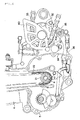
- Fig. 6 is a left side view showing a main part for explaining the arrangement of a gear position sensor.
- Fig. 7 is a sectional view showing a main part including the gear position sensor.
- Referring to the drawings, a preferred embodiment of the invention will be described below. First, referring to Fig. 1, an engine 1 where a splash guard mechanism according to the invention is used will be described. The engine 1 is applied to a motorcycle, particularly a sport motorcycle used for off road driving. In the following description, an arrow F shown in Fig. 1 shall point to the front.
- The engine 1 is configured by a
cylinder head cover 2, acylinder head 3, acylinder block 4 and acrankcase 5. Acylinder chamber 6 extended vertically and cylindrically is formed in thecylinder block 4. In thiscylinder chamber 6, apiston 7 is arranged so that the piston can be vertically slid and is connected to acrankshaft 9 rotatably held in thecrankcase 5 via a connectingrod 8. The connectingrod 8 is connected to thecrankshaft 9 by acrankpin 28. Anintake port 13 and anexhaust port 14 communicate with acombustion chamber 10 formed by thecylinder chamber 6, thecylinder head 3 and thepiston 7 via an inlet 11 and anoutlet 12 respectively formed in thecylinder head 3. The respective one ends of anintake poppet valve 15 and anexhaust poppet valve 16 are attached to respective valve stems, are supported by respective retainers, and the respective other ends are pressed in directions in which the respective other ends ordinarily close the inlet 11 and theoutlet 12 byrespective valve springs cylinder head 3. - Further, a
camshaft 19 that opens and closes theintake valve 15 and theexhaust valve 16 is rotatably supported by thecylinder head 3 and atiming change 22 is wound on a cam drivensprocket 20 arranged on thecamshaft 19 and acam driving sprocket 21 arranged on thecrankshaft 9. Therefore, when thecamshaft 19 is rotated in accordance with the rotation of thecrankshaft 9 and acam 23 formed on thecamshaft 19 directly pushes down theintake valve 15 or pushes down theexhaust valve 16 via arocker arm 24, the inlet 11 and theoutlet 12 are opened or closed. - A
throttle valve 25 and aninjector 26 are attached to theintake port 13, the quantity of air cleaned by an air cleaner not shown that flows in is regulated by thethrottle valve 25, the air is mixed with fuel injected from theinjector 26, and they are supplied to thecombustion chamber 10 via the inlet 11 from theintake port 13. After this air-fuel mixture is compressed by thepiston 7, it is ignited by an ignition plug not shown and is combusted to be energy for rotating thecrankshaft 9 via thepiston 7, and afterward, the air-fuel mixture is exhausted outside via theexhaust port 14 from theoutlet 12 as exhaust gas. - A
transmission mechanism 27 is arranged at the back of thecrankshaft 9 in thecrankcase 5. Thetransmission mechanism 27 forms a parallel axes type transmission, and includes amain shaft 28 and acounter shaft 29 respectively arranged in parallel with thecrankshaft 9 and respectively supported by thecrankcase 5 so that they can be rotated,plural gear trains 30 arranged between themain shaft 28 and thecounter shaft 29 and ashift drum 31 that engages and disengages gears configuring thegear train 30 with/from themain shaft 28 or thecounter shaft 29 so as to shift the transmission gear ratio (shift stage) of thetransmission mechanism 27. The rotation of thecrankshaft 9 is transmitted to themain shaft 28 via a gear train not shown, is selected by theshift drum 31, and the rotation of themain shaft 28 is transmitted to thecounter shaft 29 at the gear ratio of thegear trains 30 engaged with themain shaft 28 and thecounter shaft 29. - The left end of the
counter shaft 29 is protruded from thecrankcase 5 outside and a drivingsprocket 32 is attached to the left end. Achain 33 is wound on the drivingsprocket 32 and a driven sprocket attached to a rear wheel shaft not shown, a chain transmission mechanism is formed, and the rotation of thecounter shaft 29 is transmitted to a rear wheel via the chain transmission mechanism. - Next, referring to Fig. 5, the configuration of the
shift drum 31 will be described. Theshift drum 31 is configured by ashift drum body 34 which is cylindrical and the axis of which is arranged substantially in parallel with thecrankshaft 9, aninput shaft 35 arranged substantially in parallel with thecrankshaft 9 and rotatably supported by thecrankcase 5, a change pedal 36 attached to the left end of theinput shaft 35, atransmission mechanism 37 that transmits the rotation of theinput shaft 35 to theshift drum body 34, aninput member 38 that inputs the rotation transmitted from thetransmission mechanism 37 to theshift drum body 34, alid member 39 attached to an opening at the left end of theshift drum body 34, ashift fork 44 that selects the shift stage of thetransmission mechanism 27 and agear position sensor 70 which is connected to thelid member 39 and senses shift stage selected by theshift drum body 34. -
Plural cam grooves 45 are formed on the outside face of theshift drum body 34 and the end of theshift fork 44 is fitted into each of thecam grooves 45. Theshift fork 44 is fixed to thecrankcase 5, is supported by a shiftfork supporting shaft 46 extended substantially in parallel with thecrankshaft 9 so that the shift fork can be slid laterally, and the end of the shift fork is connected to a dog clutch that engages and disengages thegear train 30 with/from themain shaft 28 or thecounter shaft 29. Therefore, when theshift fork 44 is shifted laterally along thecam grooves 45 by stepping on the change pedal 36 and rotating theshift drum body 34 and the dog clutch is operated, thegear train 30 is engaged or disengaged with/from themain shaft 28 or thecounter shaft 29 and shift stage can be selected. - In the engine 1 according to this embodiment, the
crankcase 5 is configured by combining aleft case half 5a and aright case half 5b as shown in Fig. 5, further, aleft cover member 5d is attached so that the left side of theleft case half 5a is covered (see Fig. 7), and aright cover member 5c is attached so that the right side of theright case half 5b is covered. The outside face at the right end of theshift drum body 34 is rotatably supported by theright case half 5b via a ball bearing 47. The outside face at the left end of theshift drum body 34 is rotatably supported by theleft case half 5a via a needle bearing 48. - The above-mentioned
input member 38 is coupled on the side of the right end of theshift drum body 34. The left end of theshift drum body 34 is open, an opening 34a is formed, and inside, thelid member 39 is connected. Thelid member 39 is configured by a disc type flange 39a and a connectedpart 39b extended cylindrically from the center of the flange 39a. The inside diameter of the opening 34a on the side of the left end of theshift drum body 34 is formed in the substantially same size as the flange 39a of thelid member 39 and a steppedpart 34b the inside diameter of which is smaller than the opening 34a is formed on the right side of a part supported by the needle bearing 48 of theshift drum body 34. Thelid member 39 is press-fitted to theshift drum body 34 configured as described above from the opening 34a, is pushed to thestepped part 34b, and is fixed. - A cylindrical
sensor mounting part 63 aligned with the axis of theshift drum body 34, protruded leftward and pierced laterally is formed in theleft case half 5a that supports the left end of theshift drum body 34 and thegear position sensor 70 is inserted into thesensor mounting part 63. - The
gear position sensor 70 is configured by asensor case 71 including a terminal fixing part 71 a having the substantial same size as the outside diameter of the cylindricalsensor mounting part 63 and asensing element 71 b having the substantial same size as the inside diameter of thesensor mounting part 63, aterminal base 72 attached to the terminal fixing part 71 a of thesensor case 71,plural terminals 73 attached to theterminal base 72, a rotating shaft 74 protruded outside from thesensing element 71 b of thesensor case 71 and rotatably held in thesensing element 71 b, afixing pin 75 attached to the end of the rotating shaft 74 so that the fixing pin is protruded in a direction perpendicular with the rotation axis, and acontact plate 76 arranged inside thesensing element 71 b and rotated together with the rotating shaft 74. - An
inserting groove 39d cut inside from the opening is formed at the left end of a throughhole 39c pierced laterally (in a direction of the rotation axis) and formed in the connectedpart 39b of thelid member 39 attached to theshift drum body 34, the rotating shaft 74 of thegear position sensor 70 attached into thesensor mounting part 63 is inserted into thethrough hole 39c, thefixing pin 75 provided to the end of the rotating shaft 74 is inserted into theinserting groove 39d, and the rotating shaft 74 and thelid member 39 are connected to each other. Therefore, as the rotating shaft 74 is rotated via thefixing pin 75 according to the rotation of theshift drum body 34 and a contact condition between thecontact plate 76 and theterminal 73 changes, shift stage selected by theshift drum 31 can be sensed by thegear position sensor 70 by sensing the rotational quantity of theshift drum body 34. - As described above, as the shift drum that slides the
shift fork 44 of theshift drum 31 is configured by theshift drum body 34 and thelid member 39 as different members, thelid member 39 can be produced thin by a press and others, can be lightened, and the strength required for connecting thegear position sensor 70 can be also secured. As theshift drum body 34 has the opening 34a greatly open to the side of the left end, it can be also cast without using a core when an inside cavity is produced and can be manufactured at a low cost. Theshift drum body 34 can be further lightened by machining the inside of the cavity. Therefore, the thickness of the respective members can be thinned, compared with a case that these are integrally cast, theshift drum 31 can be lightened. - As the periphery of the
shift drum body 34 is supported by theneedle bearing 48 on the side (the side of the left end) to which the rotating shaft 74 is connected in theshift drum body 34, the bearing precision can be enhanced by theneedle bearing 48. Further, as thelid member 39 is press-fitted to the right side of a part supported by the needle bearing 48 (to the inside of the shift drum body 34) in theshift drum body 34, theconnected part 39b of thelid member 39 is also located in theshift drum body 34. Therefore, the rotating shaft 74 of thegear position sensor 70 is also located in theshift drum body 34 and the lateral length of thewhole shift drum 31 can be reduced. - As shown in Fig. 1 and others, as the
shift drum 31 is arranged on the lower side between themain shaft 28 and thecounter shaft 29, thegear position sensor 70 is attached to the vicinity under the drivingsprocket 32 attached to the left end of thecounter shaft 29 as shown in Fig. 6. At this time, in a state in which thegear position sensor 70 is mounted in thesensor mounting part 63, thesensing element 71 b of thesensor case 71 is inserted into thesensor mounting part 63 and the terminal fixing part 71 a is protruded outside. Therefore, mud and others that adheres to thechain 33 wound on the drivingsprocket 32 are splashed and may adhere to thegear position sensor 70. As the gear position sensor is protruded leftward from the crankcase 5 (the left case half 5a), a stone and others splashed by a front wheel may hit the sensor. - For a guard from mud splashed from the
chain 33, first, a flat splash guard 40a is provided to asprocket cover 40 attached to the left side of thecrankcase 5 so that the sprocket cover covers the drivingsprocket 32 so as to protect the drivingsprocket 32. The splash guard 40a is located between the driving sprocket 32 (the chain 33) and thegear position sensor 70 when thesprocket cover 40 is attached to thecrankcase 5 as shown in Figs. 6 and 7. As the splash guard 40a is diagonally extended downward and backward from the upside so that the splash guard covers the rear side of thegear position sensor 70 as shown in Fig. 6 and further, the end is curved downward, mud and others splashed from thechain 33 drop downward along the splash guard 40a and never adhere to thegear position sensor 70. - At this time, a
groove 65 is formed on the side of thesensor mounting part 63 of the left case half 5a and when thesprocket cover 40 is attached to the left case half 5a, the splash guard 40a enters thegroove 65 as shown in Fig. 7. Therefore, as the splash guard 40a covers the whole side of thegear position sensor 70, mud and others splashed from thechain 33 can be securely prevented from adhering to thegear position sensor 70. - It is also conceivable that a rib for the splash guard of the
gear position sensor 70 is formed on thecrankcase 5 and a crankcase cover (right andleft cover members sprocket cover 40 has only to be replaced because the splash guard 40a is integrated with thesprocket cover 40 even if the splash guard 40a is broken, sprocket covers can be replaced at a relatively low cost. - In the meantime, a
rib 64 for storing thecam driving sprocket 21 attached to thecrankshaft 9 and others is protruded from the left side of the left case half 5a on the front side of thegear position sensor 70. Theleft cover member 5d is attached to the side of the left end of therib 64. Therefore, as the front side of thegear position sensor 70 is covered with therib 64 and theleft cover member 5d in a front view, thegear position sensor 70 is protected from a stone and others splashed from the front wheel. - As described above, as the
gear position sensor 70 attached to thecrankcase 5 is surrounded by therib 64 formed in the left case half 5a and the splash guard 40a formed on thesprocket cover 40, a special cover for thegear position sensor 70 is not required to be provided. Besides, a special man-hour for attaching the splash guard 40a is not required by forming the splash guard 40a on thesprocket cover 40 and the number of parts can be reduced. - The invention is directed to a splash guard mechanism of a gear position sensor for a motorcycle for protecting the gear position sensor without providing a special cover.
- In an engine 1 of a motorcycle where a
gear position sensor 70 that senses shift stage selected by ashift drum 31 is protruded sideway in the vicinity of a drivingsprocket 32 for driving a rear wheel by acrankcase 5 that holds acrankshaft 9, a splash guard mechanism of thegear position sensor 70 is configured by a splash guard 40a formed on asprocket cover 40 that covers the drivingsprocket 32 from the side and arranged between thegear position sensor 70 and the drivingsprocket 32, and arib 64 protruded from the reverse side of the drivingsprocket 32 with thegear position sensor 70 between them in thecrankcase 5.
Claims (3)
- A splash guard mechanism of a gear position sensor (70) for a motorcycle in an engine (1) of the motorcycle where the gear position sensor (70) that senses shift stage selected by a shift drum (31) is protruded sideway in the vicinity of a driving sprocket (32) for driving a rear wheel by a crankcase (5) that holds a crankshaft (9), comprising:a splash guard (40a) arranged between the gear position sensor (70) and the driving sprocket (32); anda rib (64) protruded from the reverse side of the driving sprocket (32) with the gear position sensor (70) between them in the crankcase (5).
- The splash guard mechanism of the gear position sensor (70) for the motorcycle according to Claim 1, wherein:the splash guard (40a) is attached to the side of the crankcase (5); andthe splash guard (40a) is integrated with a sprocket cover (40) that covers the side of the driving sprocket (32).
- The splash guard mechanism of the gear position sensor (70) for the motorcycle according to Claim 1 or 2, wherein:a groove (65) is formed in a position opposite to the splash guard (40a) of the crankcase (5); andthe splash guard (40a) is inserted into the groove (65).
Applications Claiming Priority (1)
| Application Number | Priority Date | Filing Date | Title |
|---|---|---|---|
| JP2006122914A JP4795101B2 (en) | 2006-04-27 | 2006-04-27 | Mudguard mechanism of motorcycle gear position sensor |
Publications (3)
| Publication Number | Publication Date |
|---|---|
| EP1849694A2 true EP1849694A2 (en) | 2007-10-31 |
| EP1849694A3 EP1849694A3 (en) | 2010-09-08 |
| EP1849694B1 EP1849694B1 (en) | 2012-01-04 |
Family
ID=38294101
Family Applications (1)
| Application Number | Title | Priority Date | Filing Date |
|---|---|---|---|
| EP07006740A Not-in-force EP1849694B1 (en) | 2006-04-27 | 2007-03-30 | Splash guard mechanism of a gear position sensor for motorcycle |
Country Status (6)
| Country | Link |
|---|---|
| US (1) | US7357114B2 (en) |
| EP (1) | EP1849694B1 (en) |
| JP (1) | JP4795101B2 (en) |
| AU (1) | AU2007201431B2 (en) |
| CA (1) | CA2584363C (en) |
| ES (1) | ES2376897T3 (en) |
Cited By (4)
| Publication number | Priority date | Publication date | Assignee | Title |
|---|---|---|---|---|
| EP1975469A3 (en) * | 2007-03-30 | 2011-09-21 | Honda Motor Co., Ltd. | Transmission for vehicle |
| CN101782018B (en) * | 2009-01-16 | 2013-01-02 | 本田技研工业株式会社 | Motor bicycle |
| EP2182192A3 (en) * | 2008-10-28 | 2014-12-31 | Yamaha Hatsudoki Kabushiki Kaisha | Engine and motorcycle including the same |
| CN105675282A (en) * | 2016-03-16 | 2016-06-15 | 骆伟法 | Steady shaft part detection device and using method thereof |
Families Citing this family (8)
| Publication number | Priority date | Publication date | Assignee | Title |
|---|---|---|---|---|
| JP4698461B2 (en) * | 2006-03-28 | 2011-06-08 | 本田技研工業株式会社 | Shift drum device |
| JP2009214813A (en) | 2008-03-12 | 2009-09-24 | Honda Motor Co Ltd | Motorcycle |
| JP5140529B2 (en) | 2008-09-25 | 2013-02-06 | 本田技研工業株式会社 | Single cylinder engine for motorcycles |
| JP5331491B2 (en) * | 2009-01-09 | 2013-10-30 | 本田技研工業株式会社 | Engine cover structure |
| JP6190098B2 (en) * | 2012-06-14 | 2017-08-30 | 川崎重工業株式会社 | Sprocket cover for saddle riding type vehicle |
| US9046447B2 (en) * | 2012-12-27 | 2015-06-02 | Hyundai Motor Company | Crank angle detection apparatus |
| JP6293523B2 (en) * | 2014-03-11 | 2018-03-14 | 本田技研工業株式会社 | Chain drive structure of chain drive type power transmission mechanism |
| JP6991450B2 (en) * | 2017-09-13 | 2022-01-12 | カワサキモータース株式会社 | Saddle-type vehicle |
Citations (1)
| Publication number | Priority date | Publication date | Assignee | Title |
|---|---|---|---|---|
| JPH07230741A (en) | 1994-02-17 | 1995-08-29 | Honda Motor Co Ltd | Change switch support device |
Family Cites Families (7)
| Publication number | Priority date | Publication date | Assignee | Title |
|---|---|---|---|---|
| US4733741A (en) * | 1986-09-02 | 1988-03-29 | Swanson Daniel L | Wear plate for a motorcycle |
| JPH01102094U (en) * | 1987-12-28 | 1989-07-10 | ||
| JPH02109787A (en) * | 1988-10-18 | 1990-04-23 | Honda Motor Co Ltd | Motorcycle sprocket cover sound insulation structure |
| JPH05221375A (en) * | 1992-02-14 | 1993-08-31 | Yamaha Motor Co Ltd | Chain driving gear fro motorcycle |
| JPH09142356A (en) * | 1995-11-24 | 1997-06-03 | Suzuki Motor Corp | Driving status display device for small vehicles |
| JP3952541B2 (en) * | 1997-06-03 | 2007-08-01 | スズキ株式会社 | Assist device for motorcycle |
| JP4163356B2 (en) * | 1999-12-22 | 2008-10-08 | 本田技研工業株式会社 | Rider riding saddle-type vehicle |
-
2006
- 2006-04-27 JP JP2006122914A patent/JP4795101B2/en not_active Expired - Fee Related
-
2007
- 2007-03-30 EP EP07006740A patent/EP1849694B1/en not_active Not-in-force
- 2007-03-30 ES ES07006740T patent/ES2376897T3/en active Active
- 2007-03-30 AU AU2007201431A patent/AU2007201431B2/en not_active Ceased
- 2007-04-11 CA CA002584363A patent/CA2584363C/en not_active Expired - Fee Related
- 2007-04-24 US US11/790,239 patent/US7357114B2/en active Active
Patent Citations (1)
| Publication number | Priority date | Publication date | Assignee | Title |
|---|---|---|---|---|
| JPH07230741A (en) | 1994-02-17 | 1995-08-29 | Honda Motor Co Ltd | Change switch support device |
Cited By (4)
| Publication number | Priority date | Publication date | Assignee | Title |
|---|---|---|---|---|
| EP1975469A3 (en) * | 2007-03-30 | 2011-09-21 | Honda Motor Co., Ltd. | Transmission for vehicle |
| EP2182192A3 (en) * | 2008-10-28 | 2014-12-31 | Yamaha Hatsudoki Kabushiki Kaisha | Engine and motorcycle including the same |
| CN101782018B (en) * | 2009-01-16 | 2013-01-02 | 本田技研工业株式会社 | Motor bicycle |
| CN105675282A (en) * | 2016-03-16 | 2016-06-15 | 骆伟法 | Steady shaft part detection device and using method thereof |
Also Published As
| Publication number | Publication date |
|---|---|
| US20070251346A1 (en) | 2007-11-01 |
| CA2584363A1 (en) | 2007-10-27 |
| AU2007201431B2 (en) | 2009-06-04 |
| JP4795101B2 (en) | 2011-10-19 |
| JP2007290640A (en) | 2007-11-08 |
| EP1849694B1 (en) | 2012-01-04 |
| AU2007201431A1 (en) | 2007-11-15 |
| EP1849694A3 (en) | 2010-09-08 |
| US7357114B2 (en) | 2008-04-15 |
| ES2376897T3 (en) | 2012-03-20 |
| CA2584363C (en) | 2010-03-09 |
Similar Documents
| Publication | Publication Date | Title |
|---|---|---|
| EP1849694B1 (en) | Splash guard mechanism of a gear position sensor for motorcycle | |
| KR100864352B1 (en) | Shift drum device | |
| US8662025B2 (en) | Ignition plug cooling device of vehicle-use engine | |
| CA1172963A (en) | Economical engine construction | |
| EP1849969B1 (en) | Lubrication structure of engine | |
| CA2472431C (en) | Four-stroke engine system | |
| EP2112360B1 (en) | Monolithic block and valve train for a four-stroke engine | |
| US4507917A (en) | Economical engine construction having integrally cast muffler | |
| US7584733B2 (en) | Mounting structure of ignition plug tube | |
| US20110056462A1 (en) | Four cycle engine carburetors | |
| JP4628161B2 (en) | Intake device for vehicle-mounted engine | |
| EP1707852B1 (en) | Transmission structure of power unit for vehicle | |
| US20070119299A1 (en) | Engine for model | |
| JP4270950B2 (en) | Engine piston cooling structure | |
| JP5456612B2 (en) | Decompression device for internal combustion engine | |
| JPH05156904A (en) | Four-cycle engine valve mechanism lubricator | |
| US20040000216A1 (en) | Connecting rod for internal combustion engine | |
| JPH05156916A (en) | Valve system lubricating device for four-cycle engine | |
| JP2000104626A (en) | Cylinder head cover for internal combustion engine | |
| JPH11200819A (en) | Cam shaft for valve system of ohc engine | |
| JP2005090373A (en) | 4 cycle engine intake system | |
| RU2001110135A (en) | MULTI-FUEL INTERMEDIATE INJECTION FOR INTERNAL COMBUSTION ENGINES |
Legal Events
| Date | Code | Title | Description |
|---|---|---|---|
| PUAI | Public reference made under article 153(3) epc to a published international application that has entered the european phase |
Free format text: ORIGINAL CODE: 0009012 |
|
| 17P | Request for examination filed |
Effective date: 20070330 |
|
| AK | Designated contracting states |
Kind code of ref document: A2 Designated state(s): AT BE BG CH CY CZ DE DK EE ES FI FR GB GR HU IE IS IT LI LT LU LV MC MT NL PL PT RO SE SI SK TR |
|
| AX | Request for extension of the european patent |
Extension state: AL BA HR MK YU |
|
| PUAL | Search report despatched |
Free format text: ORIGINAL CODE: 0009013 |
|
| AK | Designated contracting states |
Kind code of ref document: A3 Designated state(s): AT BE BG CH CY CZ DE DK EE ES FI FR GB GR HU IE IS IT LI LT LU LV MC MT NL PL PT RO SE SI SK TR |
|
| AX | Request for extension of the european patent |
Extension state: AL BA HR MK RS |
|
| AKX | Designation fees paid |
Designated state(s): DE ES FR GB IT |
|
| RIC1 | Information provided on ipc code assigned before grant |
Ipc: B62J 13/00 20060101AFI20110427BHEP |
|
| GRAP | Despatch of communication of intention to grant a patent |
Free format text: ORIGINAL CODE: EPIDOSNIGR1 |
|
| GRAS | Grant fee paid |
Free format text: ORIGINAL CODE: EPIDOSNIGR3 |
|
| GRAA | (expected) grant |
Free format text: ORIGINAL CODE: 0009210 |
|
| RIN1 | Information on inventor provided before grant (corrected) |
Inventor name: TAKI, MASAFUMI |
|
| AK | Designated contracting states |
Kind code of ref document: B1 Designated state(s): DE ES FR GB IT |
|
| REG | Reference to a national code |
Ref country code: GB Ref legal event code: FG4D |
|
| REG | Reference to a national code |
Ref country code: DE Ref legal event code: R096 Ref document number: 602007019767 Country of ref document: DE Effective date: 20120301 |
|
| REG | Reference to a national code |
Ref country code: ES Ref legal event code: FG2A Ref document number: 2376897 Country of ref document: ES Kind code of ref document: T3 Effective date: 20120320 |
|
| PLBE | No opposition filed within time limit |
Free format text: ORIGINAL CODE: 0009261 |
|
| STAA | Information on the status of an ep patent application or granted ep patent |
Free format text: STATUS: NO OPPOSITION FILED WITHIN TIME LIMIT |
|
| 26N | No opposition filed |
Effective date: 20121005 |
|
| REG | Reference to a national code |
Ref country code: DE Ref legal event code: R097 Ref document number: 602007019767 Country of ref document: DE Effective date: 20121005 |
|
| REG | Reference to a national code |
Ref country code: DE Ref legal event code: R084 Ref document number: 602007019767 Country of ref document: DE |
|
| REG | Reference to a national code |
Ref country code: GB Ref legal event code: 746 Effective date: 20141114 |
|
| REG | Reference to a national code |
Ref country code: DE Ref legal event code: R084 Ref document number: 602007019767 Country of ref document: DE Effective date: 20141120 |
|
| REG | Reference to a national code |
Ref country code: FR Ref legal event code: PLFP Year of fee payment: 10 |
|
| REG | Reference to a national code |
Ref country code: FR Ref legal event code: PLFP Year of fee payment: 11 |
|
| REG | Reference to a national code |
Ref country code: FR Ref legal event code: PLFP Year of fee payment: 12 |
|
| PGFP | Annual fee paid to national office [announced via postgrant information from national office to epo] |
Ref country code: DE Payment date: 20190319 Year of fee payment: 13 Ref country code: IT Payment date: 20190326 Year of fee payment: 13 Ref country code: GB Payment date: 20190327 Year of fee payment: 13 |
|
| PGFP | Annual fee paid to national office [announced via postgrant information from national office to epo] |
Ref country code: FR Payment date: 20190213 Year of fee payment: 13 |
|
| PGFP | Annual fee paid to national office [announced via postgrant information from national office to epo] |
Ref country code: ES Payment date: 20190401 Year of fee payment: 13 |
|
| REG | Reference to a national code |
Ref country code: DE Ref legal event code: R119 Ref document number: 602007019767 Country of ref document: DE |
|
| PG25 | Lapsed in a contracting state [announced via postgrant information from national office to epo] |
Ref country code: FR Free format text: LAPSE BECAUSE OF NON-PAYMENT OF DUE FEES Effective date: 20200331 Ref country code: DE Free format text: LAPSE BECAUSE OF NON-PAYMENT OF DUE FEES Effective date: 20201001 |
|
| GBPC | Gb: european patent ceased through non-payment of renewal fee |
Effective date: 20200330 |
|
| PG25 | Lapsed in a contracting state [announced via postgrant information from national office to epo] |
Ref country code: GB Free format text: LAPSE BECAUSE OF NON-PAYMENT OF DUE FEES Effective date: 20200330 |
|
| REG | Reference to a national code |
Ref country code: ES Ref legal event code: FD2A Effective date: 20210812 |
|
| PG25 | Lapsed in a contracting state [announced via postgrant information from national office to epo] |
Ref country code: IT Free format text: LAPSE BECAUSE OF NON-PAYMENT OF DUE FEES Effective date: 20200330 |
|
| PG25 | Lapsed in a contracting state [announced via postgrant information from national office to epo] |
Ref country code: ES Free format text: LAPSE BECAUSE OF NON-PAYMENT OF DUE FEES Effective date: 20200331 |