EP1849357B1 - A fixed spool fishing reel - Google Patents
A fixed spool fishing reel Download PDFInfo
- Publication number
- EP1849357B1 EP1849357B1 EP06256520A EP06256520A EP1849357B1 EP 1849357 B1 EP1849357 B1 EP 1849357B1 EP 06256520 A EP06256520 A EP 06256520A EP 06256520 A EP06256520 A EP 06256520A EP 1849357 B1 EP1849357 B1 EP 1849357B1
- Authority
- EP
- European Patent Office
- Prior art keywords
- spool
- axis
- winding shaft
- fishing reel
- wheel
- Prior art date
- Legal status (The legal status is an assumption and is not a legal conclusion. Google has not performed a legal analysis and makes no representation as to the accuracy of the status listed.)
- Not-in-force
Links
Images



Classifications
-
- A—HUMAN NECESSITIES
- A01—AGRICULTURE; FORESTRY; ANIMAL HUSBANDRY; HUNTING; TRAPPING; FISHING
- A01K—ANIMAL HUSBANDRY; AVICULTURE; APICULTURE; PISCICULTURE; FISHING; REARING OR BREEDING ANIMALS, NOT OTHERWISE PROVIDED FOR; NEW BREEDS OF ANIMALS
- A01K89/00—Reels
- A01K89/01—Reels with pick-up, i.e. with the guiding member rotating and the spool not rotating during normal retrieval of the line
-
- A—HUMAN NECESSITIES
- A01—AGRICULTURE; FORESTRY; ANIMAL HUSBANDRY; HUNTING; TRAPPING; FISHING
- A01K—ANIMAL HUSBANDRY; AVICULTURE; APICULTURE; PISCICULTURE; FISHING; REARING OR BREEDING ANIMALS, NOT OTHERWISE PROVIDED FOR; NEW BREEDS OF ANIMALS
- A01K89/00—Reels
- A01K89/01—Reels with pick-up, i.e. with the guiding member rotating and the spool not rotating during normal retrieval of the line
- A01K89/0114—Reciprocating mechanisms
-
- A—HUMAN NECESSITIES
- A01—AGRICULTURE; FORESTRY; ANIMAL HUSBANDRY; HUNTING; TRAPPING; FISHING
- A01K—ANIMAL HUSBANDRY; AVICULTURE; APICULTURE; PISCICULTURE; FISHING; REARING OR BREEDING ANIMALS, NOT OTHERWISE PROVIDED FOR; NEW BREEDS OF ANIMALS
- A01K89/00—Reels
- A01K89/06—Reversible reels, i.e. with spool axis shiftable between winding and unwinding positions
Definitions
- the present invention relates to a fixed spool fishing reel having a winding shaft wheel, preferably a crown wheel, which is rotatable about the winding shaft axis by operation of a handle on the winding shaft and which engages a rotor drive which rotates about a first axis which is generally transverse of the winding shaft axis and which drives a spool reciprocating worm shaft, which is rotatable about a second axis generally parallel to the said first axis, the winding shaft being provided with winding shaft attachment means on both sides of the winding shaft wheel, so that a winding handle may be attached selectively to either one or the other of the two sides of the reel.
- a winding shaft wheel preferably a crown wheel
- Such a fishing reel is disclosed in US-B-6,626,385 in which the winding shaft has a narrowed central portion to accommodate a spool shaft.
- Such a construction provides the benefit of enabling a line to be laid on the spool with one turn placed beside the next turn without any gap or without much of a gap.
- This has advantages over the 'aero' type of lay, in which there are relatively few turns of the rotor for each forward or rearward linear movement of the spool. Firstly, it gives a smoother and freer release of the line upon casting or playing of a fish. Secondly, it decreases the damage to the line by virtue of there being fewer and less damaging cross-overs between successive turns of the line around the spool. Cross-overs can cause the line to bite into itself. This can cause kinks, especially in nylon monofilament line. Such damage can significantly reduce the length of useful life of the line.
- a disadvantage of such a construction as proposed hitherto is that the arrangement of the rotor drive, worm shaft and reduction gear is such as to prevent attachment of a winding handle of the reel selectively on one side of the reel main body or on the other side thereof.
- the present invention seeks to provide a remedy.
- the present invention is directed to a fixed spool fishing reel having the construction set out in the opening paragraph of the present specification, in which the rotor drive drives the spool reciprocating worm shaft via reduction gearing which rotates about a third axis generally parallel to the said first and second axes, the said first, second and third axes all being on the same side of the plane of the winding shaft wheel.
- the reduction gearing may comprise two cog wheels which are fixed relative to one another but which are rotatable about the said third axis, the two cog wheels being of different respective diameters, the cog wheel of greater diameter engaging the rotor drive and the cog wheel of smaller diameter engaging a gear wheel fixed to the spool reciprocating worm shaft.
- the cog wheel of greater diameter may have in the range from about 10 teeth to about 16 teeth, preferably thirteen, and the cog wheel of smaller diameter may have in the range from about five teeth to about ten teeth, preferably seven.
- the gearing and worm shaft construction may be such as to cause the rotor drive to rotate in the range from about 15 times to 50 times, for example 22 times, for every linear movement, forwards or backwards, of the spool, depending upon the length of the spool and the cross-sectional diameter of the line.
- the gearing may comprise bevelled gearing, and it may be helical or part helical.
- the winding shaft is arranged in a position above the rotor drive axis with the fishing reel in its intended orientation, and both the reduction gearing axis and the worm shaft axis are arranged below the winding shaft.
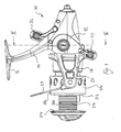
- the fishing reel 10 shown in Figures 1 to 5 comprises a main body 12, a suspension leg 14 extending upwardly from the main body, a mounting foot 16 extending transversely of the leg 14 at an upper end thereof in an intended forward/rearward direction, a generally U-shaped rotor 18 mounted on an intended front end of the body 12 with its limbs 20 and 22 directed forwardly, a spool 24 mounted on the body 12 between the arms of the rotor 18, a line clip 26 secured to the spool 24, a bail 28 having respective ends pivoted to the forward ends of the limbs 20 and 22 respectively, and a line guide 30 arranged between one end of the bail 28 and its associated limb 22.
- a double-ended winding handle 32 is attached to a winding shaft 210 which extends within a housing 34 of the body 12 to one side of the main body 12 of the fishing reel 10. It may be selectively attached to that side or to the other side of the main body 12.
- the various parts of the fishing reel 10 may be made of an appropriately hard synthetic plastics material, or of metal, stamp or die cast.
- the bail 28 and with it the line guide 30 are pivotable about the ends of the limbs 20 and 22 between a line-guiding position as illustrated in Figure 1 , in which the line is guided onto the spool 24, and a line-release position, in which the bail 28 is rotated 180° about the ends of the limbs 20 and 22, relative to the position shown in Figure 1 , to take the bail 28 and the guide 30 out of the way of the line.
- the plane of the line guide 30 is generally parallel with the axis of the spool 24, and the bail 28 extends around the spool 24.
- a spool shaft 224 extends along this latter axis and is inhibited from rotation about that axis by bearings (not shown).
- the spool 24 is mounted on the forward end of the spool shaft 224. The latter is shown in its extended forward position in Figure 5 .
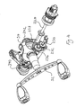
- a rearward end of the spool shaft 224 is coupled to a worm shaft 226 having an axis which is generally parallel to the spool shaft 224, in such a fashion that rotation of the worm shaft 226 causes reciprocating linear movement of the spool 24 along the spool shaft axis.
- the worm shaft 226 is coupled to be driven by reduction gearing 228 via a gear or cog wheel 230 fixed to one end of the worm shaft 226.
- the cog wheel 230 engages a further cog wheel 232 having seven teeth in this example embodiment, which further cog wheel is one of two coaxial cog wheels forming reduction gearing 228, the other cog wheel 236 of which is of larger diameter than cog wheel 232 and has thirteen teeth in this example embodiment.
- the reduction gearing axis is held within the main body 12 generally parallel to the spool shaft axis and to the worm shaft 226.
- an elongate helically splined rotor drive 238 coupled to rotate with rotor 18.
- a crown wheel 240 fixed to the winding shaft 210 to rotate about the axis thereof has its teeth intermeshing with the splines of the rotor drive 238, which in turn intermesh with the teeth of the cog wheel 236, being the larger of the two cog wheels which constitute the reduction gearing 234.
- rotation of the handle 32 causes rotation of the crown wheel 240, to rotate the rotor drive 238 and with it the rotor 18, to rotate the reduction gearing 228, to rotate the cog wheel 230 and with it the worm shaft 226, to reciprocate the spool shaft 224 and with it the spool 24.
- the gearing and worm drive construction is such as to provide twenty-two rotations of the rotor 18 for every forward linear movement of the spool 24, and for every rearward linear movement of the spool 24.
- Portions of the winding shaft 210 extend from both sides of the crown wheel 240 and the main body 12 to enable the handle 32 to be selectively mounted on the shaft 34 on either one or the other side of the main body 12, so that the reel is ambidextrous.
- the unused portion 210 may be covered by a cap 242.
- the spool 24 comprises a cylindrical portion 310 on to which fishing line (not shown) is wound when the fishing reel 10 is in use, respective circular flange portions 312 and 314 which are at respective opposite ends of the cylindrical portion 310, which are integral therewith, and which extend outwardly therefrom, and a cylindrical skirt portion 316 extending in an intended rearward direction from and integral with the intended rearward flange 312.
- the diameter of the spool is substantially 60mm and the depth of each of its flanges is about 28mm.
- a clutch mechanism 340 shown in Figure 5 comes into effect.
- the line may only be paid out by rotation of the spool 24 to feed out the fishing line via the guide 30, with the clutch construction 340 shown in Figure 5 acting as a drag.
- slack may be taken up by rotation of the handle 32 so that the line is retrieved and laid down on the cylindrical portion 310 of the spool 24 as already described herein.
- the clutch arrangement 340 as shown in Figure 5 ensures a uniform action of the clutch which can be adjusted with precision and which at the same time does not result in wobble of the reel 24 on the shaft 224 which could adversely affect the laying of the line on the spool.
- winding shaft 210 may be arranged offset from the rotor drive 238 therebelow rather than thereabove, and the axes of the reduction gear 228 and the worm shaft 226 may be positioned above the winding shaft 210 rather than below it.
Landscapes
- Life Sciences & Earth Sciences (AREA)
- Environmental Sciences (AREA)
- Animal Husbandry (AREA)
- Biodiversity & Conservation Biology (AREA)
Abstract
Description
- The present invention relates to a fixed spool fishing reel having a winding shaft wheel, preferably a crown wheel, which is rotatable about the winding shaft axis by operation of a handle on the winding shaft and which engages a rotor drive which rotates about a first axis which is generally transverse of the winding shaft axis and which drives a spool reciprocating worm shaft, which is rotatable about a second axis generally parallel to the said first axis, the winding shaft being provided with winding shaft attachment means on both sides of the winding shaft wheel, so that a winding handle may be attached selectively to either one or the other of the two sides of the reel.
- Such a fishing reel is disclosed in
US-B-6,626,385 in which the winding shaft has a narrowed central portion to accommodate a spool shaft. - Such a construction provides the benefit of enabling a line to be laid on the spool with one turn placed beside the next turn without any gap or without much of a gap. This has advantages over the 'aero' type of lay, in which there are relatively few turns of the rotor for each forward or rearward linear movement of the spool. Firstly, it gives a smoother and freer release of the line upon casting or playing of a fish. Secondly, it decreases the damage to the line by virtue of there being fewer and less damaging cross-overs between successive turns of the line around the spool. Cross-overs can cause the line to bite into itself. This can cause kinks, especially in nylon monofilament line. Such damage can significantly reduce the length of useful life of the line.
- A disadvantage of such a construction as proposed hitherto is that the arrangement of the rotor drive, worm shaft and reduction gear is such as to prevent attachment of a winding handle of the reel selectively on one side of the reel main body or on the other side thereof.
- The present invention seeks to provide a remedy.
- Accordingly, the present invention is directed to a fixed spool fishing reel having the construction set out in the opening paragraph of the present specification, in which the rotor drive drives the spool reciprocating worm shaft via reduction gearing which rotates about a third axis generally parallel to the said first and second axes, the said first, second and third axes all being on the same side of the plane of the winding shaft wheel.
- The reduction gearing may comprise two cog wheels which are fixed relative to one another but which are rotatable about the said third axis, the two cog wheels being of different respective diameters, the cog wheel of greater diameter engaging the rotor drive and the cog wheel of smaller diameter engaging a gear wheel fixed to the spool reciprocating worm shaft.
- The cog wheel of greater diameter may have in the range from about 10 teeth to about 16 teeth, preferably thirteen, and the cog wheel of smaller diameter may have in the range from about five teeth to about ten teeth, preferably seven.
- The gearing and worm shaft construction may be such as to cause the rotor drive to rotate in the range from about 15 times to 50 times, for example 22 times, for every linear movement, forwards or backwards, of the spool, depending upon the length of the spool and the cross-sectional diameter of the line.
- The gearing may comprise bevelled gearing, and it may be helical or part helical.
- Preferably, the winding shaft is arranged in a position above the rotor drive axis with the fishing reel in its intended orientation, and both the reduction gearing axis and the worm shaft axis are arranged below the winding shaft.
- An example of a fishing reel made in accordance with the present invention will now be described with reference to the accompanying drawings, in which:
- Figure 1
- shows a side view of a fishing reel embodying the present invention;
- Figure 2
- shows a cross-section of the reel taken in the plane indicated by the line II-II shown in
Figure 1 ; - Figure 3
- shows a view of parts of the reel shown in
Figures 1 and2 , along a central axis thereof, with some parts removed for the sake of clarity; - Figure 4
- shows a perspective view of the parts shown in
Figure 3 , with further parts added; and - Figure 5
- shows a side view of the parts shown in
Figure 4 with yet further parts added. - The
fishing reel 10 shown inFigures 1 to 5 comprises amain body 12, asuspension leg 14 extending upwardly from the main body, amounting foot 16 extending transversely of theleg 14 at an upper end thereof in an intended forward/rearward direction, a generallyU-shaped rotor 18 mounted on an intended front end of thebody 12 with itslimbs spool 24 mounted on thebody 12 between the arms of therotor 18, aline clip 26 secured to thespool 24, abail 28 having respective ends pivoted to the forward ends of thelimbs line guide 30 arranged between one end of thebail 28 and its associatedlimb 22. A double-ended winding handle 32 is attached to awinding shaft 210 which extends within ahousing 34 of thebody 12 to one side of themain body 12 of thefishing reel 10. It may be selectively attached to that side or to the other side of themain body 12. - The various parts of the
fishing reel 10 may be made of an appropriately hard synthetic plastics material, or of metal, stamp or die cast. - The
bail 28 and with it theline guide 30 are pivotable about the ends of thelimbs Figure 1 , in which the line is guided onto thespool 24, and a line-release position, in which thebail 28 is rotated 180° about the ends of thelimbs Figure 1 , to take thebail 28 and theguide 30 out of the way of the line. In the line-guiding position, the plane of theline guide 30 is generally parallel with the axis of thespool 24, and thebail 28 extends around thespool 24. - A
spool shaft 224 extends along this latter axis and is inhibited from rotation about that axis by bearings (not shown). - The
spool 24 is mounted on the forward end of thespool shaft 224. The latter is shown in its extended forward position inFigure 5 . A rearward end of thespool shaft 224 is coupled to aworm shaft 226 having an axis which is generally parallel to thespool shaft 224, in such a fashion that rotation of theworm shaft 226 causes reciprocating linear movement of thespool 24 along the spool shaft axis. Theworm shaft 226 is coupled to be driven by reduction gearing 228 via a gear orcog wheel 230 fixed to one end of theworm shaft 226. Thecog wheel 230 engages afurther cog wheel 232 having seven teeth in this example embodiment, which further cog wheel is one of two coaxial cog wheels forming reduction gearing 228, theother cog wheel 236 of which is of larger diameter thancog wheel 232 and has thirteen teeth in this example embodiment. The reduction gearing axis is held within themain body 12 generally parallel to the spool shaft axis and to theworm shaft 226. - Surrounding and coaxial with the
spool shaft 224 is an elongate helically splinedrotor drive 238 coupled to rotate withrotor 18. Acrown wheel 240 fixed to thewinding shaft 210 to rotate about the axis thereof has its teeth intermeshing with the splines of therotor drive 238, which in turn intermesh with the teeth of thecog wheel 236, being the larger of the two cog wheels which constitute the reduction gearing 234. - As a result, rotation of the
handle 32 causes rotation of thecrown wheel 240, to rotate therotor drive 238 and with it therotor 18, to rotate thereduction gearing 228, to rotate thecog wheel 230 and with it theworm shaft 226, to reciprocate thespool shaft 224 and with it thespool 24. The gearing and worm drive construction is such as to provide twenty-two rotations of therotor 18 for every forward linear movement of thespool 24, and for every rearward linear movement of thespool 24. - Portions of the
winding shaft 210 extend from both sides of thecrown wheel 240 and themain body 12 to enable thehandle 32 to be selectively mounted on theshaft 34 on either one or the other side of themain body 12, so that the reel is ambidextrous. Theunused portion 210 may be covered by acap 242. - The
spool 24 comprises acylindrical portion 310 on to which fishing line (not shown) is wound when thefishing reel 10 is in use, respectivecircular flange portions cylindrical portion 310, which are integral therewith, and which extend outwardly therefrom, and acylindrical skirt portion 316 extending in an intended rearward direction from and integral with the intendedrearward flange 312. The diameter of the spool is substantially 60mm and the depth of each of its flanges is about 28mm. - With the
bail 28 in its line-release position, and a line (not shown) wound around thespool 24, and held temporarily, where the line leaves the spool, by a user's finger against the rod to stop the line unravelling from thespool 24, a weight and hook assembly (not shown) at one end of the line can be cast so that the line on the spool unwinds whilst thespool 24 remains stationary relative to themain body 12 of thefishing reel 10. Thebail 28 may now be rotated by the user to its line-guiding position and any slack on the line may be taken up by rotation of thehandle 32. Initially such rotation causes the fishing line to be directed by thebail 28 onto theguide 30, and thereafter wound around thecylindrical portion 310 of thespool 24 by virtue of the rotation of therotor 18 and with it thebail 28 and theguide 30. Thus, line extending from the weight and hook arrangement is guided by thebail 28 on to theguide 30 where the line turns through a right angle and then extends on to thecylindrical portion 310 of thespool 24. As the line is wound on to thecylindrical portion 310, the reciprocation of the spool ensures that successive turns of the line around thecylindrical portion 310 are laid neatly adjacent to the immediately preceding turn without excessive spacing and at the same time without any crossing of successive turns. - In the event of a subsequent strike when a fish bites on the hook (not shown), and the angler is ready to play the fish, a
clutch mechanism 340 shown inFigure 5 comes into effect. At this stage the line may only be paid out by rotation of thespool 24 to feed out the fishing line via theguide 30, with theclutch construction 340 shown inFigure 5 acting as a drag. In the event that the fish swims towards the fishing reel, slack may be taken up by rotation of thehandle 32 so that the line is retrieved and laid down on thecylindrical portion 310 of thespool 24 as already described herein. Theclutch arrangement 340 as shown inFigure 5 ensures a uniform action of the clutch which can be adjusted with precision and which at the same time does not result in wobble of thereel 24 on theshaft 224 which could adversely affect the laying of the line on the spool. - The illustrated embodiment is given by way of example only. Many variations may occur to the reader without taking the resulting construction outside the scope of the present invention as claimed in the claims. For example, the
winding shaft 210 may be arranged offset from therotor drive 238 therebelow rather than thereabove, and the axes of thereduction gear 228 and theworm shaft 226 may be positioned above thewinding shaft 210 rather than below it.
Claims (10)
- A fixed spool fishing reel (10) having a winding shaft wheel (240) which is rotatable about the winding shaft axis by operation of a handle (32) on the winding shaft (210) and which engages a rotor drive (238) which rotates about a first axis which is generally transverse of the winding shaft axis and which drives a spool reciprocating worm shaft (226), which is rotatable about a second axis generally parallel to the said first axis, the winding shaft (210) being provided with winding shaft attachment means on both sides of the winding shaft wheel, so that a winding handle (32) may be attached selectively to either one or the other of the two sides of the reel (10), characterised in that the rotor drive (238) drives the spool reciprocating worm shaft (226) via reduction gearing (228) which rotates about a third axis generally parallel to the said first and second axes, the said first, second and third axes all being on the same side of the plane of the winding shaft wheel (240).
- A fixed spool fishing reel according to claim 1, characterised in that the reduction gearing (228) comprises two cog wheels (232, 236) which are fixed relative to one another but which are rotatable about the said third axis, the two cog wheels (232, 236) being of different respective diameters, the cog wheel (236) of greater diameter engaging the rotor drive (238) and the cog wheel (232) of smaller diameter engaging a gear wheel (230) fixed to the spool reciprocating worm shaft (226).
- A fixed spool fishing reel according to claim 2, characterised in that the cog wheel (236) of greater diameter has in the range from ten teeth to sixteen teeth, and the cog wheel (232) of smaller diameter has in the range from five teeth to ten teeth.
- A fixed spool fishing reel according to claim 3, characterised in that the cog wheel (236) of greater diameter has thirteen teeth.
- A fixed spool fishing reel according to claim 3 or claim 4, characterised in that the cog wheel (232) of smaller diameter has seven teeth.
- A fixed spool fishing reel according to any preceding claim, characterised in that the gearing (228) and worm shaft (226) construction is such as to cause the rotor drive (238) to rotate in the range from 15 times to 50 times for every linear movement, forwards or backwards, of the spool (24), depending upon the length of the spool (24) and the cross-sectional diameter of the line.
- A fixed spool fishing reel according to claim 6, characterised in that the gearing (228) and worm shaft (226) construction is such as to cause the rotor drive (238) to rotate 22 times for every linear movement, forwards or backwards, of the spool (24), depending upon the length of the spool (24) and the cross-sectional diameter of the line.
- A fixed spool fishing reel according to any preceding claim, characterised in that the gearing (228) comprises bevelled gearing.
- A fixed spool fishing reel according to any preceding claim, characterised in that the gearing (228) is helical or part helical.
- A fixed spool fishing reel according to any preceding claim, characterised in that the winding shaft (210) is arranged in a position above the rotor drive (238) axis with the fishing reel (10) in its intended orientation, and both the reduction gearing (228) axis and the worm shaft (226) axis are arranged below the winding shaft (210).
Applications Claiming Priority (1)
| Application Number | Priority Date | Filing Date | Title |
|---|---|---|---|
| GBGB0608383.6A GB0608383D0 (en) | 2006-04-27 | 2006-04-27 | A fixed spool fishing reel |
Publications (2)
| Publication Number | Publication Date |
|---|---|
| EP1849357A1 EP1849357A1 (en) | 2007-10-31 |
| EP1849357B1 true EP1849357B1 (en) | 2008-06-25 |
Family
ID=36589948
Family Applications (1)
| Application Number | Title | Priority Date | Filing Date |
|---|---|---|---|
| EP06256520A Not-in-force EP1849357B1 (en) | 2006-04-27 | 2006-12-21 | A fixed spool fishing reel |
Country Status (6)
| Country | Link |
|---|---|
| US (1) | US20070278335A1 (en) |
| EP (1) | EP1849357B1 (en) |
| CN (1) | CN101061795A (en) |
| AT (1) | ATE398923T1 (en) |
| DE (1) | DE602006001582D1 (en) |
| GB (2) | GB0608383D0 (en) |
Families Citing this family (8)
| Publication number | Priority date | Publication date | Assignee | Title |
|---|---|---|---|---|
| GB0905869D0 (en) * | 2009-04-03 | 2009-05-20 | Fox Int Group Ltd | A fixed spool fishing reel |
| US7967232B2 (en) * | 2009-10-28 | 2011-06-28 | Shimano Inc. | Spinning-reel fishing line guide mechanism |
| US8469300B2 (en) | 2011-07-22 | 2013-06-25 | Eastaboga Tacle Mfg. Co., Inc. | Spinning reel |
| USD681155S1 (en) | 2012-07-26 | 2013-04-30 | Eastaboga Tackle Mfg. Co., Inc. | Rotor for fishing reel |
| CN103004713B (en) * | 2012-11-30 | 2014-05-07 | 宁波海宝渔具有限公司 | Gear-driven gapless fishing line reel for fishing |
| GB2515507A (en) * | 2013-06-25 | 2014-12-31 | Heligear Engineering H K Co Ltd | Fishing reel |
| CN107157088B (en) * | 2017-05-31 | 2024-02-06 | 余姚市德威电器电机有限公司 | Electric hair drier with wire winding speed reducer |
| JP7778524B2 (en) * | 2021-10-15 | 2025-12-02 | 株式会社シマノ | Spinning reel |
Family Cites Families (7)
| Publication number | Priority date | Publication date | Assignee | Title |
|---|---|---|---|---|
| GB582695A (en) * | 1944-10-16 | 1946-11-25 | James Robert Young | Improvements in or connected with fishing reels |
| JP2001321041A (en) * | 2000-05-18 | 2001-11-20 | Shimano Inc | Spinning reel reciprocating device |
| JP2002017213A (en) * | 2000-07-06 | 2002-01-22 | Shimano Inc | Spinning reel reciprocating device |
| JP2003225040A (en) * | 2002-02-04 | 2003-08-12 | Shimano Inc | Power transmission device for fishing reel |
| US6626385B1 (en) * | 2002-08-01 | 2003-09-30 | Daiwa Seiko, Inc. | Spinning reel for fishing |
| JP4015957B2 (en) * | 2003-01-20 | 2007-11-28 | 株式会社シマノ | Spinning reel handle assembly |
| JP4250035B2 (en) * | 2003-05-13 | 2009-04-08 | 株式会社シマノ | Spinning reel master gear |
-
2006
- 2006-04-27 GB GBGB0608383.6A patent/GB0608383D0/en not_active Ceased
- 2006-12-21 DE DE602006001582T patent/DE602006001582D1/en active Active
- 2006-12-21 GB GB0625606A patent/GB2433405B/en not_active Expired - Fee Related
- 2006-12-21 EP EP06256520A patent/EP1849357B1/en not_active Not-in-force
- 2006-12-21 AT AT06256520T patent/ATE398923T1/en not_active IP Right Cessation
-
2007
- 2007-01-12 CN CNA2007100017159A patent/CN101061795A/en active Pending
- 2007-04-20 US US11/785,770 patent/US20070278335A1/en not_active Abandoned
Also Published As
| Publication number | Publication date |
|---|---|
| GB2433405A (en) | 2007-06-27 |
| GB0608383D0 (en) | 2006-06-07 |
| ATE398923T1 (en) | 2008-07-15 |
| DE602006001582D1 (en) | 2008-08-07 |
| GB2433405B (en) | 2010-11-24 |
| US20070278335A1 (en) | 2007-12-06 |
| GB0625606D0 (en) | 2007-01-31 |
| CN101061795A (en) | 2007-10-31 |
| EP1849357A1 (en) | 2007-10-31 |
Similar Documents
| Publication | Publication Date | Title |
|---|---|---|
| US20070278335A1 (en) | Fixed spool fishing reel | |
| US7896277B2 (en) | Fishing reel | |
| US5934586A (en) | Oscillation mechanism for spinning reel | |
| CN104430229B (en) | Dual-bearing fishing reel | |
| US2783952A (en) | Spinning reel | |
| KR20140039983A (en) | Drive gear | |
| JP2010273629A (en) | Fishing reel handle assembly | |
| KR101081832B1 (en) | Level winding mechanism for a dual bearing reel | |
| EP2413690B1 (en) | A fixed spool fishing reel | |
| US20240245043A1 (en) | Left handed fishing reel | |
| ATE488994T1 (en) | OSCILLATOR FOR FISHING COILS | |
| CN103355270B (en) | Double-bearing fish-line wheel and double-bearing fish-line wheel unload power functional unit | |
| US9723825B2 (en) | Fishing reel drive gear and fishing reel pinion gear meshed with same | |
| US4436254A (en) | Spinning reel for fly-fishing | |
| EP1588614A2 (en) | Fishing reel | |
| KR102762281B1 (en) | Hook keeper, and fishing reel | |
| US5467932A (en) | Line guide for fishing reels | |
| JP2004135624A (en) | Fishing reel | |
| US20220174922A1 (en) | Bottle-Style Reel Bow-Fishing Reel Out of Plane Bottle Axis | |
| US2538153A (en) | Spin casting reel | |
| JP2012005423A (en) | Spinning reel for fishing | |
| KR101346721B1 (en) | Fishing reel | |
| EP1094702B1 (en) | Improved lightweight spinning reel with large diameter spool | |
| US401049A (en) | And charles raettig | |
| KR101128447B1 (en) | Spinning reel |
Legal Events
| Date | Code | Title | Description |
|---|---|---|---|
| PUAI | Public reference made under article 153(3) epc to a published international application that has entered the european phase |
Free format text: ORIGINAL CODE: 0009012 |
|
| 17P | Request for examination filed |
Effective date: 20070425 |
|
| AK | Designated contracting states |
Kind code of ref document: A1 Designated state(s): AT BE BG CH CY CZ DE DK EE ES FI FR GB GR HU IE IS IT LI LT LU LV MC NL PL PT RO SE SI SK TR |
|
| AX | Request for extension of the european patent |
Extension state: AL BA HR MK YU |
|
| GRAP | Despatch of communication of intention to grant a patent |
Free format text: ORIGINAL CODE: EPIDOSNIGR1 |
|
| GRAS | Grant fee paid |
Free format text: ORIGINAL CODE: EPIDOSNIGR3 |
|
| GRAA | (expected) grant |
Free format text: ORIGINAL CODE: 0009210 |
|
| AK | Designated contracting states |
Kind code of ref document: B1 Designated state(s): AT BE BG CH CY CZ DE DK EE ES FI FR GB GR HU IE IS IT LI LT LU LV MC NL PL PT RO SE SI SK TR |
|
| REG | Reference to a national code |
Ref country code: GB Ref legal event code: FG4D |
|
| AKX | Designation fees paid |
Designated state(s): AT BE BG CH CY CZ DE DK EE ES FI FR GB GR HU IE IS IT LI LT LU LV MC NL PL PT RO SE SI SK TR |
|
| REG | Reference to a national code |
Ref country code: CH Ref legal event code: EP |
|
| REF | Corresponds to: |
Ref document number: 602006001582 Country of ref document: DE Date of ref document: 20080807 Kind code of ref document: P |
|
| REG | Reference to a national code |
Ref country code: IE Ref legal event code: FG4D |
|
| PG25 | Lapsed in a contracting state [announced via postgrant information from national office to epo] |
Ref country code: SI Free format text: LAPSE BECAUSE OF FAILURE TO SUBMIT A TRANSLATION OF THE DESCRIPTION OR TO PAY THE FEE WITHIN THE PRESCRIBED TIME-LIMIT Effective date: 20080625 Ref country code: FI Free format text: LAPSE BECAUSE OF FAILURE TO SUBMIT A TRANSLATION OF THE DESCRIPTION OR TO PAY THE FEE WITHIN THE PRESCRIBED TIME-LIMIT Effective date: 20080625 |
|
| PG25 | Lapsed in a contracting state [announced via postgrant information from national office to epo] |
Ref country code: AT Free format text: LAPSE BECAUSE OF FAILURE TO SUBMIT A TRANSLATION OF THE DESCRIPTION OR TO PAY THE FEE WITHIN THE PRESCRIBED TIME-LIMIT Effective date: 20080625 Ref country code: PL Free format text: LAPSE BECAUSE OF FAILURE TO SUBMIT A TRANSLATION OF THE DESCRIPTION OR TO PAY THE FEE WITHIN THE PRESCRIBED TIME-LIMIT Effective date: 20080625 |
|
| REG | Reference to a national code |
Ref country code: EE Ref legal event code: FG4A Ref document number: E002384 Country of ref document: EE Effective date: 20080729 |
|
| PG25 | Lapsed in a contracting state [announced via postgrant information from national office to epo] |
Ref country code: SE Free format text: LAPSE BECAUSE OF FAILURE TO SUBMIT A TRANSLATION OF THE DESCRIPTION OR TO PAY THE FEE WITHIN THE PRESCRIBED TIME-LIMIT Effective date: 20080925 Ref country code: IS Free format text: LAPSE BECAUSE OF FAILURE TO SUBMIT A TRANSLATION OF THE DESCRIPTION OR TO PAY THE FEE WITHIN THE PRESCRIBED TIME-LIMIT Effective date: 20081025 |
|
| PG25 | Lapsed in a contracting state [announced via postgrant information from national office to epo] |
Ref country code: RO Free format text: LAPSE BECAUSE OF FAILURE TO SUBMIT A TRANSLATION OF THE DESCRIPTION OR TO PAY THE FEE WITHIN THE PRESCRIBED TIME-LIMIT Effective date: 20080625 Ref country code: PT Free format text: LAPSE BECAUSE OF FAILURE TO SUBMIT A TRANSLATION OF THE DESCRIPTION OR TO PAY THE FEE WITHIN THE PRESCRIBED TIME-LIMIT Effective date: 20081125 Ref country code: SK Free format text: LAPSE BECAUSE OF FAILURE TO SUBMIT A TRANSLATION OF THE DESCRIPTION OR TO PAY THE FEE WITHIN THE PRESCRIBED TIME-LIMIT Effective date: 20080625 Ref country code: ES Free format text: LAPSE BECAUSE OF FAILURE TO SUBMIT A TRANSLATION OF THE DESCRIPTION OR TO PAY THE FEE WITHIN THE PRESCRIBED TIME-LIMIT Effective date: 20081006 |
|
| PG25 | Lapsed in a contracting state [announced via postgrant information from national office to epo] |
Ref country code: BG Free format text: LAPSE BECAUSE OF FAILURE TO SUBMIT A TRANSLATION OF THE DESCRIPTION OR TO PAY THE FEE WITHIN THE PRESCRIBED TIME-LIMIT Effective date: 20080925 Ref country code: DK Free format text: LAPSE BECAUSE OF FAILURE TO SUBMIT A TRANSLATION OF THE DESCRIPTION OR TO PAY THE FEE WITHIN THE PRESCRIBED TIME-LIMIT Effective date: 20080625 |
|
| PLBE | No opposition filed within time limit |
Free format text: ORIGINAL CODE: 0009261 |
|
| STAA | Information on the status of an ep patent application or granted ep patent |
Free format text: STATUS: NO OPPOSITION FILED WITHIN TIME LIMIT |
|
| 26N | No opposition filed |
Effective date: 20090326 |
|
| PG25 | Lapsed in a contracting state [announced via postgrant information from national office to epo] |
Ref country code: MC Free format text: LAPSE BECAUSE OF NON-PAYMENT OF DUE FEES Effective date: 20081231 |
|
| REG | Reference to a national code |
Ref country code: IE Ref legal event code: MM4A |
|
| PG25 | Lapsed in a contracting state [announced via postgrant information from national office to epo] |
Ref country code: IE Free format text: LAPSE BECAUSE OF NON-PAYMENT OF DUE FEES Effective date: 20081221 |
|
| PG25 | Lapsed in a contracting state [announced via postgrant information from national office to epo] |
Ref country code: HU Free format text: LAPSE BECAUSE OF FAILURE TO SUBMIT A TRANSLATION OF THE DESCRIPTION OR TO PAY THE FEE WITHIN THE PRESCRIBED TIME-LIMIT Effective date: 20081226 Ref country code: CY Free format text: LAPSE BECAUSE OF FAILURE TO SUBMIT A TRANSLATION OF THE DESCRIPTION OR TO PAY THE FEE WITHIN THE PRESCRIBED TIME-LIMIT Effective date: 20080625 |
|
| PG25 | Lapsed in a contracting state [announced via postgrant information from national office to epo] |
Ref country code: TR Free format text: LAPSE BECAUSE OF FAILURE TO SUBMIT A TRANSLATION OF THE DESCRIPTION OR TO PAY THE FEE WITHIN THE PRESCRIBED TIME-LIMIT Effective date: 20080625 |
|
| PG25 | Lapsed in a contracting state [announced via postgrant information from national office to epo] |
Ref country code: GR Free format text: LAPSE BECAUSE OF FAILURE TO SUBMIT A TRANSLATION OF THE DESCRIPTION OR TO PAY THE FEE WITHIN THE PRESCRIBED TIME-LIMIT Effective date: 20080926 |
|
| PG25 | Lapsed in a contracting state [announced via postgrant information from national office to epo] |
Ref country code: IT Free format text: LAPSE BECAUSE OF NON-PAYMENT OF DUE FEES Effective date: 20091221 |
|
| PGRI | Patent reinstated in contracting state [announced from national office to epo] |
Ref country code: IT Effective date: 20110616 |
|
| REG | Reference to a national code |
Ref country code: CH Ref legal event code: PL |
|
| PG25 | Lapsed in a contracting state [announced via postgrant information from national office to epo] |
Ref country code: LI Free format text: LAPSE BECAUSE OF NON-PAYMENT OF DUE FEES Effective date: 20101231 Ref country code: CH Free format text: LAPSE BECAUSE OF NON-PAYMENT OF DUE FEES Effective date: 20101231 |
|
| PGFP | Annual fee paid to national office [announced via postgrant information from national office to epo] |
Ref country code: LU Payment date: 20121221 Year of fee payment: 7 Ref country code: CZ Payment date: 20121213 Year of fee payment: 7 Ref country code: LT Payment date: 20121212 Year of fee payment: 7 Ref country code: EE Payment date: 20121212 Year of fee payment: 7 |
|
| PGFP | Annual fee paid to national office [announced via postgrant information from national office to epo] |
Ref country code: LV Payment date: 20121218 Year of fee payment: 7 Ref country code: IT Payment date: 20121218 Year of fee payment: 7 |
|
| REG | Reference to a national code |
Ref country code: DE Ref legal event code: R082 Ref document number: 602006001582 Country of ref document: DE Representative=s name: VP-IP VON PUTTKAMER BERNGRUBER LOTH SPUHLER PA, DE Ref country code: DE Ref legal event code: R082 Ref document number: 602006001582 Country of ref document: DE Representative=s name: LS-MP VON PUTTKAMER BERNGRUBER LOTH SPUHLER PA, DE Ref country code: DE Ref legal event code: R082 Ref document number: 602006001582 Country of ref document: DE Representative=s name: LS-MP VON PUTTKAMER BERNGRUBER LOTH SPUHLER MU, DE |
|
| PGFP | Annual fee paid to national office [announced via postgrant information from national office to epo] |
Ref country code: FR Payment date: 20130104 Year of fee payment: 7 |
|
| PGFP | Annual fee paid to national office [announced via postgrant information from national office to epo] |
Ref country code: DE Payment date: 20130215 Year of fee payment: 7 Ref country code: BE Payment date: 20121231 Year of fee payment: 7 |
|
| PGFP | Annual fee paid to national office [announced via postgrant information from national office to epo] |
Ref country code: NL Payment date: 20121228 Year of fee payment: 7 |
|
| BERE | Be: lapsed |
Owner name: FOX INTERNATIONAL GROUP LTD Effective date: 20131231 |
|
| REG | Reference to a national code |
Ref country code: DE Ref legal event code: R119 Ref document number: 602006001582 Country of ref document: DE |
|
| REG | Reference to a national code |
Ref country code: NL Ref legal event code: V1 Effective date: 20140701 |
|
| REG | Reference to a national code |
Ref country code: EE Ref legal event code: MM4A Ref document number: E002384 Country of ref document: EE Effective date: 20131231 |
|
| REG | Reference to a national code |
Ref country code: LT Ref legal event code: MM4D Effective date: 20131221 |
|
| PG25 | Lapsed in a contracting state [announced via postgrant information from national office to epo] |
Ref country code: LU Free format text: LAPSE BECAUSE OF NON-PAYMENT OF DUE FEES Effective date: 20131221 Ref country code: CZ Free format text: LAPSE BECAUSE OF NON-PAYMENT OF DUE FEES Effective date: 20131221 |
|
| REG | Reference to a national code |
Ref country code: FR Ref legal event code: ST Effective date: 20140829 |
|
| PG25 | Lapsed in a contracting state [announced via postgrant information from national office to epo] |
Ref country code: LV Free format text: LAPSE BECAUSE OF NON-PAYMENT OF DUE FEES Effective date: 20131221 |
|
| REG | Reference to a national code |
Ref country code: DE Ref legal event code: R119 Ref document number: 602006001582 Country of ref document: DE Effective date: 20140701 |
|
| PG25 | Lapsed in a contracting state [announced via postgrant information from national office to epo] |
Ref country code: BE Free format text: LAPSE BECAUSE OF NON-PAYMENT OF DUE FEES Effective date: 20131231 Ref country code: LT Free format text: LAPSE BECAUSE OF NON-PAYMENT OF DUE FEES Effective date: 20131221 Ref country code: DE Free format text: LAPSE BECAUSE OF NON-PAYMENT OF DUE FEES Effective date: 20140701 Ref country code: EE Free format text: LAPSE BECAUSE OF NON-PAYMENT OF DUE FEES Effective date: 20131231 Ref country code: NL Free format text: LAPSE BECAUSE OF NON-PAYMENT OF DUE FEES Effective date: 20140701 |
|
| PG25 | Lapsed in a contracting state [announced via postgrant information from national office to epo] |
Ref country code: FR Free format text: LAPSE BECAUSE OF NON-PAYMENT OF DUE FEES Effective date: 20131231 |
|
| PG25 | Lapsed in a contracting state [announced via postgrant information from national office to epo] |
Ref country code: IT Free format text: LAPSE BECAUSE OF NON-PAYMENT OF DUE FEES Effective date: 20131231 |
|
| PG25 | Lapsed in a contracting state [announced via postgrant information from national office to epo] |
Ref country code: IT Free format text: LAPSE BECAUSE OF NON-PAYMENT OF DUE FEES Effective date: 20131221 |
|
| PGFP | Annual fee paid to national office [announced via postgrant information from national office to epo] |
Ref country code: GB Payment date: 20221229 Year of fee payment: 17 |
|
| GBPC | Gb: european patent ceased through non-payment of renewal fee |
Effective date: 20231221 |
|
| PG25 | Lapsed in a contracting state [announced via postgrant information from national office to epo] |
Ref country code: GB Free format text: LAPSE BECAUSE OF NON-PAYMENT OF DUE FEES Effective date: 20231221 |
|
| PG25 | Lapsed in a contracting state [announced via postgrant information from national office to epo] |
Ref country code: GB Free format text: LAPSE BECAUSE OF NON-PAYMENT OF DUE FEES Effective date: 20231221 |