EP1849154B1 - Methods and apparatus for use in sound modification - Google Patents
Methods and apparatus for use in sound modification Download PDFInfo
- Publication number
- EP1849154B1 EP1849154B1 EP06709573A EP06709573A EP1849154B1 EP 1849154 B1 EP1849154 B1 EP 1849154B1 EP 06709573 A EP06709573 A EP 06709573A EP 06709573 A EP06709573 A EP 06709573A EP 1849154 B1 EP1849154 B1 EP 1849154B1
- Authority
- EP
- European Patent Office
- Prior art keywords
- signal
- pitch
- time
- feature
- acoustic feature
- Prior art date
- Legal status (The legal status is an assumption and is not a legal conclusion. Google has not performed a legal analysis and makes no representation as to the accuracy of the status listed.)
- Active
Links
Images


Classifications
-
- G—PHYSICS
- G10—MUSICAL INSTRUMENTS; ACOUSTICS
- G10H—ELECTROPHONIC MUSICAL INSTRUMENTS; INSTRUMENTS IN WHICH THE TONES ARE GENERATED BY ELECTROMECHANICAL MEANS OR ELECTRONIC GENERATORS, OR IN WHICH THE TONES ARE SYNTHESISED FROM A DATA STORE
- G10H1/00—Details of electrophonic musical instruments
- G10H1/36—Accompaniment arrangements
- G10H1/361—Recording/reproducing of accompaniment for use with an external source, e.g. karaoke systems
- G10H1/366—Recording/reproducing of accompaniment for use with an external source, e.g. karaoke systems with means for modifying or correcting the external signal, e.g. pitch correction, reverberation, changing a singer's voice
-
- G—PHYSICS
- G10—MUSICAL INSTRUMENTS; ACOUSTICS
- G10H—ELECTROPHONIC MUSICAL INSTRUMENTS; INSTRUMENTS IN WHICH THE TONES ARE GENERATED BY ELECTROMECHANICAL MEANS OR ELECTRONIC GENERATORS, OR IN WHICH THE TONES ARE SYNTHESISED FROM A DATA STORE
- G10H2210/00—Aspects or methods of musical processing having intrinsic musical character, i.e. involving musical theory or musical parameters or relying on musical knowledge, as applied in electrophonic musical tools or instruments
- G10H2210/031—Musical analysis, i.e. isolation, extraction or identification of musical elements or musical parameters from a raw acoustic signal or from an encoded audio signal
- G10H2210/066—Musical analysis, i.e. isolation, extraction or identification of musical elements or musical parameters from a raw acoustic signal or from an encoded audio signal for pitch analysis as part of wider processing for musical purposes, e.g. transcription, musical performance evaluation; Pitch recognition, e.g. in polyphonic sounds; Estimation or use of missing fundamental
-
- G—PHYSICS
- G10—MUSICAL INSTRUMENTS; ACOUSTICS
- G10H—ELECTROPHONIC MUSICAL INSTRUMENTS; INSTRUMENTS IN WHICH THE TONES ARE GENERATED BY ELECTROMECHANICAL MEANS OR ELECTRONIC GENERATORS, OR IN WHICH THE TONES ARE SYNTHESISED FROM A DATA STORE
- G10H2210/00—Aspects or methods of musical processing having intrinsic musical character, i.e. involving musical theory or musical parameters or relying on musical knowledge, as applied in electrophonic musical tools or instruments
- G10H2210/031—Musical analysis, i.e. isolation, extraction or identification of musical elements or musical parameters from a raw acoustic signal or from an encoded audio signal
- G10H2210/076—Musical analysis, i.e. isolation, extraction or identification of musical elements or musical parameters from a raw acoustic signal or from an encoded audio signal for extraction of timing, tempo; Beat detection
-
- G—PHYSICS
- G10—MUSICAL INSTRUMENTS; ACOUSTICS
- G10H—ELECTROPHONIC MUSICAL INSTRUMENTS; INSTRUMENTS IN WHICH THE TONES ARE GENERATED BY ELECTROMECHANICAL MEANS OR ELECTRONIC GENERATORS, OR IN WHICH THE TONES ARE SYNTHESISED FROM A DATA STORE
- G10H2210/00—Aspects or methods of musical processing having intrinsic musical character, i.e. involving musical theory or musical parameters or relying on musical knowledge, as applied in electrophonic musical tools or instruments
- G10H2210/375—Tempo or beat alterations; Music timing control
- G10H2210/391—Automatic tempo adjustment, correction or control
-
- G—PHYSICS
- G10—MUSICAL INSTRUMENTS; ACOUSTICS
- G10H—ELECTROPHONIC MUSICAL INSTRUMENTS; INSTRUMENTS IN WHICH THE TONES ARE GENERATED BY ELECTROMECHANICAL MEANS OR ELECTRONIC GENERATORS, OR IN WHICH THE TONES ARE SYNTHESISED FROM A DATA STORE
- G10H2240/00—Data organisation or data communication aspects, specifically adapted for electrophonic musical tools or instruments
- G10H2240/325—Synchronizing two or more audio tracks or files according to musical features or musical timings
-
- G—PHYSICS
- G10—MUSICAL INSTRUMENTS; ACOUSTICS
- G10L—SPEECH ANALYSIS TECHNIQUES OR SPEECH SYNTHESIS; SPEECH RECOGNITION; SPEECH OR VOICE PROCESSING TECHNIQUES; SPEECH OR AUDIO CODING OR DECODING
- G10L21/00—Speech or voice signal processing techniques to produce another audible or non-audible signal, e.g. visual or tactile, in order to modify its quality or its intelligibility
- G10L21/003—Changing voice quality, e.g. pitch or formants
- G10L21/007—Changing voice quality, e.g. pitch or formants characterised by the process used
- G10L21/013—Adapting to target pitch
- G10L2021/0135—Voice conversion or morphing
Definitions
- the present invention relates to methods and apparatus for modifying at least one acoustic feature of an audio signal.
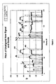
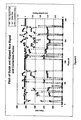
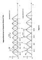
- FIG. 4 displays pitch measurements of a professional singer (Guide Pitch 401) and a member of the public (New Pitch 402) singing of the same words to the same musical track.
- the timing discrepancies between the onsets and offsets of corresponding sections (pulses) of voiced signals (non- zero Hz pitch values) as well as positions of unvoiced or silent sections (at zero Hz) are frequent and significant.
- Applying pitch data from the Guide Pitch 401 directly at the same relative times to the data of the New Pitch 402 would clearly be wrong and inappropriate for a substantial amount of the segment shown. This is a typical result and illustrates the basic problems to be solved.
- the fundamental basis for target pitch identification in such known software and hardware devices is a musical scale, which is basically a list of those specific notes' frequencies to which the device should first compare the input signal.
- Most devices come with preset musical scales for standard scales and allow customisation of these, for example to change the target pitches or to leave certain pitched notes unaltered.
- the known software devices can be set to an automatic mode, which is also generally how the hardware devices work: the device detects the input pitch, identifies the closest scale note in a user-specified preset scale, and changes the input signal such that the output pitch matches the pitch of the specified scale's note.
- the rate at which the output pitch is slewed and retuned to the target pitch is controlled to help maintain natural pitch contours (i.e. pitch as a function of time) more accurately and naturally and allow a wider variety of "styles".
- US 6836761 describes a voice converting apparatus in which successive time frames of data from a target voice are stored, an input signal from a user's voice is analyzed to extract data of the same type from a successive of time frames of the signal, and an output signal is synthesised by utilizing data from the target voice in accordance with data from corresponding frames of the input signal.
- this timing alignment path must be used as a time map to determine and apply the feature (e.g. pitch) adjustments correctly to the new vocal performance at precisely the right times.
- this permits nuances and complexity found in the guiding vocal performance (e.g. for pitch: vibrato, inflection curves, glides, jumps, etc.) to be imposed on the new vocal performance.
- other features in addition to or as an alternative to pitch can be controlled; for example glottal characteristics (e.g. breathy or raspy voice), vocal tract resonances, EQ, and others.
- Another objective of this invention is to provide methods for vocal modifications that operate under non-ideal input signal conditions, especially where the new input (e.g. user voice): (a) is band-limited and/or limited in dynamic range (for example input via a telephone system); (b) contains certain types of noise or distortion; or (c) is from a person with a different accent, sex, or age from the guiding (target) voice, or with very different timing of delivery of words and phonemes whether they are the same or different from the guiding (target) signal and even with different input languages.
- the new input e.g. user voice
- a further objective is to provide a method that does not require any prior information on either signal to be stored e.g. regarding the phonemic nature of the signals, or the detailed set of possible signal states that could be applied to the output signal.
- a related further objective is to provide a method that can operate with a guiding audio signal and a new audio signal, either or both of which are not required to be speech or singing.
- Preferred embodiments of this invention provide methods and apparatus for automatically and correctly modifying one or more signal characteristics of a second digitized audio signal to be a function of specified features in a first digitized audio signal.
- the relative timing relationships of specified features in both signals are first established. Based on these timing relationships, detailed and time-critical modifications of the signal's features can be applied correctly.
- a time-alignment function is generated to create a mapping between features of the first signal and features of the second signal and provide a function for optionally editing the second (user's) signal.
- Particular applications of this invention include accurately transferring selected audio characteristics of a professional performer's digitized vocal performance to - and thereby enhancing - the digitized audio performance of a less skilled person.
- One specific application of this invention is that of automatically adjusting the pitch of a new audio signal ("New Signal") generated by a typical member of the public to follow the pitch of another audio signal (“Guide Signal”) generated by a professional singer.
- New Signal a new audio signal
- Guide Signal another audio signal generated by a professional singer.
- An example of this is a karaoke-style recording and playback system using digitized music videos as the original source in which, during a playback of the original audio and optional corresponding video, the user's voice is digitized and input to the apparatus (as the New recording). With this system, a modified user's voice signal can be created that is automatically time and pitch corrected.
- the modified voice signal When the modified voice signal is played back synchronously with the original video, the user's voice can accurately replace the original performer's recorded voice in terms of both pitch and time, including any lip synching. During playback of the music video, the impact of this replacement will be even more effective if the original, replaced voice signal is not audible during the playback with the user's modified voice recording.
- the modified voice recording can be combined with the original backing music as described in WO 2004/040576 .
- An additional application of this invention is in the creation of a personalized sound file for use in telephone systems.
- the user sings or even speaks to provide a voice signal that is recorded and then enhanced (for example pitch and time corrected to follow the characteristics of a professional singer's version) and optionally mixed with an appropriate backing track.
- the resulting enhanced user recording can then be made available to phone users as a personalized ringtone or sound file for other purposes.
- Apparatus embodying the invention may then take the form of, for example, a server computer coupled into a telecommunications system comprising a telecommunications network and /or the Internet, and may utilise mobile phone as an interface between the apparatus and users. Additionally or alternatively, a mobile phone may be adapted to embody the invention.
- a modified voice signal, or data representing such a signal, produced by an embodiment of the invention may be transmitted to a selected recipient through a ringtone delivery system to be used as a ring tone or other identifying sound signal.
- the inclusion of the step of creating a time-dependent mapping function between the Guide and New Signals ensures that the signal feature modifications are made at the appropriate times within the New Signal regardless of substantial differences between the two signals.
- the time alignment function is used to map the control feature function data to the desired signal modification process.
- the modification process accesses a New Signal and modifies it as required. This action creates a new third audio signal from the New Signal. Accordingly, the third signal then has the desired time varying features determined by the features specified as control features of the Guide Signal.
- a second audio signal, the New Signal is time-modified (non-linearly time compressed or expanded) using the mapping information from the time alignment function so that its time-varying features align in time with a first audio signal, the Guide Signal.
- This time alignment can take place before or after the desired modifications described above have taken place.
- the time alignment process is not performed on the new or modified waveform. Instead the time-warping path is used to map the control features of the first signal (Guide Signal audio control parameters) to the second signal in order to modify the appropriate parts of the second signal's waveform and keep its original timing.
- the time-warping path is used to map the control features of the first signal (Guide Signal audio control parameters) to the second signal in order to modify the appropriate parts of the second signal's waveform and keep its original timing.
- Sets of output feature values for the New Signal do not have to be pre-defined. For example if the pitch of a New Signal provided by a user is to be corrected to match the pitch of a Guide Signal in the form of a recording of a professional singer, the acceptable pitch values do not need to be defined or set. Instead, the user's voice will be adjusted to the values that are present and measured in the Guide Signal recording.
- the New Signal does not have to be restricted to resemble the Guide Signal or be generated by the same type of acoustic processes as the Guide Signal. For example, monotonic speech could be time and pitch modified to follow a solo woodwind instrument or a bird chirping. As long as both signals have some time-varying features that can be treated as related, a method embodying the invention can create an output signal with appropriately modified properties. Furthermore, features of the New Signal and the Guide Signal may be offset in frequencies from one another. For example, the pitch of one signal may be an octave or more apart from the other signal.
- one or both audio signals may be in the ultra sound or infra sound regions.
- the complex and skilled pitch variations (and, optionally other characteristics) found in the performance of a professional singer can be accurately transferred to the digitized voice of a user (e.g. amateur) singer. This enhances many aspects of the user's performance to the professional's level.
- Embodiments of the invention can also be applied in the field of Automatic Dialogue Replacement (ADR) to enhance an actor's ADR studio-recorded performance.
- ADR Automatic Dialogue Replacement
- An embodiment can be used to modify the studio-recording's vocal characteristics such as pitch, energy level and prosodic features to match or follow those of the original Guide Signal recorded on set or location with the image.
- the actor in the studio can be a different actor from the one who recorded the Guide Signal.
- the invention is flexible in the range of processes that can be applied.
- further pitch changing functions such as time-aligned harmony generation, can be introduced as functions of the pitch adjustment function to create alternative output signals.
- one measured feature in the Guide Signal can be mapped by an arbitrary function to control another entirely different feature in the New Signal.
- Methods embodying this invention can be implemented with computer programs in a computer system such as a PC or computer-based games console with means for audio input and output.
- the New and Guide Signals are sampled and stored digitally.
- a robust, speaker-independent short time feature analysis extracts the profiles of feature modulations in both signals. Spectral energy measurements are made every 10ms over successive windowed "frames" of the signals, with noise and level compensation algorithms provided (for example as described in US patent 4,591,928 ). This analysis is performed over the entire input signal to maximise the accuracy and robustness of the processing.
- Other short-term feature measurements can alternatively be used, examples of which can be found in L.R. Rabiner and R.W. Schafer (1978) "Digital Processing of Speech Signals," Prentice Hall .
- Method 1 employs two editing algorithms in cascade and measures the pitch of the New Signal after it has undergone one step of editing.
- the quality of the generated output in Method 1 is dependent on the output quality of the edited signal from step (b). Consequently imperfections introduced during editing in that signal can degrade the quality of outputs of steps (d) and (f). This could lead to occasional small errors in the corrected pitch and possibly create a subtle roughness in the generated output.
- any characteristic of the New Signal is measured from the unmodified New Signal, and not from a time-aligned (edited) version. This is achieved by calculating the inverse of the time alignment path.
- the inverse path maps each frame of the unedited New Signal to its corresponding frame of the Guide Signal. From this mapping a pitch correction contour for the New Signal is calculated that is aligned in time to the Guide Signal. In effect the Guide Signal is being aligned in time to the New Signal before the pitch correction contour is calculated.
- Method 2 provides a more reliable and natural sounding pitch correction over all words and phrases, which can follow and recreate faithfully any subtle nuances such as vibrato and other details.
- Method 2 only edits the New Signal once, it utilises a processing technique that modifies the pitch and time alignment at the same time. By varying the sequence of steps slightly it is possible to separately process the pitch shifting and time modification without using Method 1. Although this introduces two stages of editing, the most appropriate specialised processing algorithms can be chosen separately for each stage.
- Method 3 uses the original time alignment path function and not the inverse. Moreover, it has the advantage as in Method 2 that the pitch of the unmodified New Signal is measured and not that of a time-aligned (edited) version. However, it cannot modify the pitch of the New Signal (step g) without first generating a time-aligned version (step f).
- other features of a sound signal besides pitch can be modified to follow those in a Guide Signal, once a time alignment function has been created.
- the additional types of time-synchronous modifiable features include the modification of sound signal features such as instantaneous loudness, equalization, speech formant or resonant patterns, reverberation and echo characteristics, and even words themselves, given a suitable mechanism for analysis and modification of the specified feature is available.
- a video signal is not necessary, and the input audio signal may be required to only accompany or replace another audio signal.
- a means for determining a time alignment function or time warping path, that can provide an optimal and sufficiently detailed time mapping between the time varying features of a second (New) audio signal corresponding with time-varying features in a first (Guide) audio signal.
- This mapping ensures that the time-varying alterations are based on the specified features in the portion of the Guide (control) signal that corresponds to the appropriate portion of the New Signal being modified.
- Measurements of specific time-varying features used for determining the time alignment are made every T seconds, on short portions or windows of the sampled signal's waveforms, each window being of duration T', and T' may be different from T. Measurements are made on a successive frame-by-frame basis, usually with the sampling windows overlapping. This is "short-time" signal analysis, as described in L.R. Rabiner and R.W. Schafer (1978) "Digital Processing of Speech Signals," Prentice Hall .
- the features measured for the time alignment process are likely to be features different from both the features being altered and the features used as a control.
- a functional relationship between the features to be altered and the control feature parameters must be defined. For example, one simple relationship described in more detail hereinafter, modifies the pitch of a New Signal to match that of a Guide Signal, with adjustments to maintain the natural pitch range of a person who creates the New Signal.
- This definition of the modification function, and other definitions, can additionally be varied with time if desired.
- the modification function can be programmed as a data array of output values vs. input values, or as a mathematical function or as a set of processing rules in the audio processing computer system. Note that this function is not necessarily dependent on the signal itself and so the signal may not need any analysis.
- the feature specified to be modified in the second signal and the specified control feature in the first signal are both measured as functions of time. These measurements are stored as data.
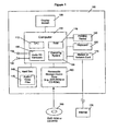
- FIG. 1 of the accompanying drawings The components of a typical PC system and environment that can support these functions are presented in FIG. 1 of the accompanying drawings and this system can be used with the software in FIG. 2 as the basis of providing the hardware and software environment for multiple embodiments of this present invention.
- FIG. 1 a conventional computer system 100 is shown which consists of a computer 110 with a CPU (Central Processing Unit) 112, RAM (Random Access Memory) 118, user interface hardware typically including a pointing device 120 such as a mouse, a keyboard 125, and a display screen 130, an internal storage device 140 such as a hard disk or further RAM, a device 160 for accessing data on fixed or removable storage media 165 such as a CD ROM or DVD ROM, and optionally a modem or network interface 170 to provide access to the Internet 175.
- the pointing device 120 controls the position of a displayed screen cursor (not shown) and the selection of functions displayed on the screen 130.
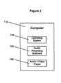
- the computer 110 may be any conventional home or business computer such as a PC or Apple Macintosh, or alternatively a dedicated "games machine” such as a Microsoft® XboxTM or Sony Playstation 2TM with the pointing device 120 then being a game controller device. Some components shown in FIG. 1 may be absent from a particular games machine. FIG. 2 illustrates further software that may be installed in the computer 110.
- a user may obtain from a CD ROM, the Internet, or other means, a digital data file 115 containing an audio and optional accompanying video clip which, for example, could be in a common format such as the avi or QuickTime® movie format and which is, for example, copied and stored on the hard disk 140 or into RAM.
- the computer 110 has a known operating system 135 such as that provided by any of the available versions of Microsoft® Windows® or Mac® OS, audio software and hardware in the form of a sound card 150 or equivalent hardware on the computer's mother board, containing an ADC (Analogue to Digital Converter) to which is connected a microphone 159 for recording and containing a DAC (Digital to Analogue Converter) to which is connected one or more loudspeakers 156 for playing back audio.
- ADC Analogue to Digital Converter
- DAC Digital to Analogue Converter
- such an operating system 135 generally is shipped with audio recording and editing software 180 that supports audio recording via the sound card 150 and editing functions, such as the "Sound Recorder" application program shipped with Windows®.
- the recording program and/or other programs can use sound card 150 to convert an incoming analogue audio signal into digital audio data and record that data in a computer file on the hard disk drive 140.
- Audio/video player software 190 such as Windows Media Player shipped with Windows® and/or other software can be used for playing composite digital video and audio files or just audio files through the sound card 150, further built-in video hardware and software, the display screen 130 and the speakers 156.
- Composite video and audio files consist of video data and one or more parallel synchronized tracks of audio data.
- audio data may be held as separate files allocated to store multiple streams of audio data.
- the audio data may be voice data such as dialogue or singing, instrumental music, "sound effects", or any combination of these.
- Blocks 180 and 190 can also, in concert with 135 and 110, represent the software and hardware that can implement the signal processing systems that will be described herein.
- Alternative distributed embodiments of the hardware and software system in 100 and 110 can be employed, one example being where the main elements of computer system 100 are provided to the user by a remote server.
- the input and output transducers 159 and 156 could be provided at the user's end by telephones or microphones and speakers connected to the user's PC system, with analogue or digitised audio signals transmitted between the user and 100 via a telephone system network and/or the Internet.
- the user can remotely control the system operation by numerous methods including a telephone touchtone keypad, a computer keyboard, voice input, or other means.
- An embodiment of this invention in the form of a non-real time consumer Karaoke system allows a member of the public record their voice singing a pop song to a music video in a computer based-system.
- the modified voice is both lip-synchronized to the original singer's mouth movements and has the same pitch variation as the replaced singer's voice in the music video.
- the system of FIG. 2 allows the audio playback of the original performer singing a song with or without an accompanying video.
- the user can play back the song and the system will digitize and record (store) the user's voice onto the computer's hard disk or other memory device.
- As there is a requirement to measure accurately features of the original singer's voice it is better to have that voice signal separate from the backing music track. This can most effectively be achieved by requesting an isolated recording of the voice from the record company or organization providing the media content.
- a first signal the Guide Signal
- the Guide Signal which is a digitized recording of the singer performing a song in isolation (e.g. the solo vocal track transferred from a multitrack recording from the original recording session), preferably without added processing such as echo or reverberation.
- Such digitized Guide Signals, g(n) can be provided to the user's system on CD or DVD/ROM 165 or via the Internet 175.
- the required features of a Guide Signal (for both time alignment and for feature modification control) can be pre-analysed in the same or another system to extract the required data.
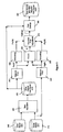
- This data can be input to the system 100 for use as data files via 165, 175 or via other data transfer methods. Data stores and processing modules of the embodiment are shown in FIG 3 .
- the user running the sound recording and playback program, plays the desired song with the original singer audible or not audible and sings at the same time.
- the user's singing is digitized and recorded into a data file in a data store 310.
- This digitized signal is the second signal, i.e. the New Signal, s(n).
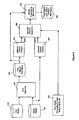
- the embodiment of FIG. 3 carries out the Method 1 described hereinbefore.
- the objective is to correct the pitch and timing of the user's New Signal to mimic the pitch and timing of the Guide Signal.
- the feature in the Guide Signal being used as a control function and the feature being modified in the New Signal are the same feature, namely the pitch contour of the respective signal.
- a process tracking the differences between time-aligned New Signal pitch measurements and the Guide Signal pitch measurements is used in computing a pitch adjustment function to make a modified New Signal's pitch follow that of the Guide Signal.
- the New Signal, s(n) is similar in phrasing, content and length to the Guide Signal, g(n). For a non-real-time Karaoke-type application, this is a reasonable assumption, because the user is normally trying to mimic the original vocal performance in timing, pitch, and words.
- Method 1 is here performed on the digital audio data in non-real time as follows.
- the first series, Pg(M) which is not aligned in time with the second series, Ps(M), cannot be directly used as a control or target pitch function for the second signal without generating significant and audible errors.
- a data point shown as zero HZ in a pitch contour 401 or 402 indicates that the corresponding pitch measurement frame contains either silence or unvoiced speech.
- the non-zero measurements indicate the pitch measurement of the respective signal in that frame.
- the non-zero value segments (pulses) of voiced sound in the New Signal pitch contour 402 generally both lag behind the corresponding features in the Guide Signal pitch contour 401 and have different durations. Also the voiced sounds of two pitch contours are in different octaves. Furthermore, the pitch range variation in each pulse of the Guide Signal pitch contour 401 is much wider than in the corresponding pulse in the New Signal pitch contour 402. This is expected since the Guide Signal pitch contour 401 is taken from a professional singer. It is such details and the timing of the Guide Signal pitch contour 401 that are to be imparted to the amateur user's recorded singing.
- the sampled New Signal waveform, s(n), read from data store 310 is first aligned in time to the Guide Signal, g(n), read from data store 312, using a technique such as that described in US 4,591,928 to create an intermediate audio signal, the Time-Aligned New Signal, s'(n), which is stored, e.g. on disk 330.
- This ensures that the details of the energy patterns in s'(n) occur at the same relative times as those in the Guide Signal. It further ensures that any required lip-syncing will be effective and any transfer of features from the Guide Signal to the New Signal needs no further time mapping.
- the sampling frequency used in creating the New Signal, s(n) and the Guide Signal g(n) in this example is 44.1 kHz.
- the Time Alignment process described in US 4,591,928 measures spectral energy features (e.g. a filterbank output) every 10ms, and generates a time alignment or "time warping" path with a path point every 10ms that associates similar spectral features in the New Signal with the closest corresponding features in the Guide Signal.
- spectral energy features e.g. a filterbank output
- a warping path is created within a time-alignment processing module 320, and this path is used to control the editing (i.e. Time-Compression/ -Expansion) of the New Signal s(n) in the module 320 in the creation of the time-aligned New Signal s'(n) stored on disk 330.
- the time-aligned New Signal, s'(n) is created by the module 320 by building up an edited version of s(n) in which portions of s(n) have been repeated or deleted according to w(k) and additional timing error feedback from the editing system, which is constrained to making pitch synchronous edits when there is voiced sound.
- the length of the analysis window be 2.5 to 3.0 times the length of the lowest period being measured. Therefore, in the current embodiment, to measure pitch as low as 72Hz with a period of approximately 0.0139 s., a 1536 sample (at 44.1 kHz sampling frequency) analysis window (or approximately 35 ms) is used.
- the sampling interval of a pitch measurement frame is 10ms.
- the analysis window of the pitch estimator module 340 is centred in each pitch measurement frame of samples.
- the measurements may be taken without overlap of analysis windows, but overlap of the successive windowed data of between 25 and 50% is generally recommended.
- the measurement frame rate of M is 100Hz (i.e. 10ms intervals), which provides a sufficient overlap and also conveniently is the same as the measurement rate of the time alignment function.
- both the start and end of the signal are padded with up to one analysis window's length of zero magnitude samples before taking those pitch measurements.
- P's'(M) for the time-aligned New Signal the pitch measurements of the individual frames are smoothed at a filter module 350 using a 3 point median filter followed by an averaging filter.
- silence and unvoiced frames of the time-aligned New Signal s'(n) are marked in P's'(M) as having zero pitch.
- a pitch contour Pg(M) of the Guide Signal g(n) is created, using the same methods and parameters as described for creating the pitch contour Ps'(M), and smoothed at a filter module 355 to create a smoothed pitch contour P'g(M) for the Guide Signal.
- the next process is calculation of the pitch adjustment or correction factor for each frame of the time-aligned New Signal.
- This is done by a pitch adjustment module 370 and takes into account the ratio of the Guide Signal pitch to the time-aligned New Signal pitch and any desired shifts in octave.
- the calculation is done for each pair of pitch measurement frames having the same frame number M.
- a low pass filter within module 370 then smoothes the correction factors.
- determination of octave and shifting of pitch of the New Signal There are two main options considered with regard to the adjustment of pitch : a) adjustment of the output pitch to be the same as the pitch of the Guide Signal or b) maintaining the pitch range of the input New Signal so that the adjusted voice sounds the most natural.
- An octave adjustment module 358 computes an octave multiplier, Q, which is kept constant for the duration of the signal. This emphasises the need to analyse all or at least a substantial amount of the New Signal before being able to set this value.
- the unsmoothed pitch estimates for frame M from the pitch estimator modules 340 and 345 are used to calculate a local pitch correction, C L (M), where M is the frame number, limiting the calculation to those frames where the time-aligned New Signal and its corresponding Guide Signal frame are both voiced, i.e. both of these frames have a valid pitch.
- Ratio C L (M) Octave Comment 0.5. up to.0.75 0.5 New Signal is one octave higher 0.75 up to 1.5 1.0 New Signal is same octave 1.5 up to 3 2.0 New Signal is one octave lower 3.0 up to 6.0 etc 4.0 New Signal is two octaves lower
- the pitch correction factor C(M) is calculated from equation (2) over all frames of the time-aligned New Signal, so that the pitch register of the modified time-aligned New Signal will most closely match that of the original New Signal.
- a correction factor, C(M), of 1.0 means no change to s'(n) at frame M; 0.5 means lower the pitch by one octave, 2.0 means raise the pitch by one octave, and so on.
- Each value C(M) in the pitch correction signal provides the correction multiplier needed for a corresponding frame M of samples of the time-aligned New Signal, s'(n).
- the frame rate of C(M) is chosen to be the same as that used by the time alignment algorithm, which is 100 frames per second or fps. In other words C(M) will have one hundred samples for every second of s'(n).
- pitch-shifting algorithms must have a frame rate much lower than that of the time-alignment algorithm; i.e. the sampling interval (analysis frame) is much longer.
- time domain pitch shifting techniques usually have a frame rate of around 25 to 30 fps if they are to work down to frequencies of 50 to 60 Hz.
- their frame rate need not be constant throughout the signal, and the rate can be varied, say, with the fundamental pitch of the signal s'(n). In the present embodiment, however, a fixed frame rate is used in pitch shifting.
- the respective frame-rates for calculation of the pitch correction factor C(M) and operation of the pitch shifting algorithm are different, and therefore linear interpolation is used to derive an estimate of the pitch correction needed at the centre of each analysis frame of the pitch shifting algorithm from the C(M) samples closest in time to that centre.
- This interpolated correction factor is derived as follows:
- the sample number along s'(n) at the centre of each of the analysis frames of the pitch shifting algorithm at which an estimate of the pitch correction is required is determined as follows.
- Nc Fps Nc ⁇ Fps - 1 + Ls ⁇ Fps , To ⁇ Fps - 1 where:
- Ls is a function of the frame number Fps and To(Fps-1), the pitch period duration at Fps-1, to allow for a time-varying frame rate.
- Ls is held constant and set to 1536 samples, i.e. 34.83 ms.
- Fc(Fps) is the pitch correction frame occurring just before or at the centre of the pitch shifting algorithm frame then (Fc(Fps) +1) will be the next pitch correction frame occurring after its centre.
- the interpolated correction factor value Cs(Fps) is smoothed by simple low pass filtering to become C's(Fps) and is represented as the output of module 370 which is supplied to the pitch changer module 380.
- the time-aligned New Signal s'(n) is processed in frames Fps corresponding to the pitch-shifting algorithm frames.
- Each such frame, Fps, of the time-aligned New Signal s'(n) is shifted dynamically in pitch by its smoothed correction factor at module 380 and the resulting pitch-corrected and time-aligned New Signal, s"(n), is written to disk 390 for subsequent playback with the backing music and optionally the corresponding music video if available.
- This output signal, s"(n) will have both the required time-alignment and pitch correction to be played back as a replacement for the Guide Signal g(n) or synchronously with it.
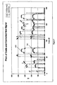
- An example of the time-aligned and corrected pitch contour 701 that would be observed in s"(n) as a result of multiplying pitch values of the time-aligned New Signal s'(n) by the corresponding correction factor values illustrated in FIG. 6 is shown in FIG. 7 .
- Most of the details of the Guide Signal pitch contour 401 now appear in this example of a computed modified pitch contour 701.
- the pitch shifting performed by the module 380 to create the pitch corrected time-aligned output signal waveform, s"(n) at store 390 can be achieved using any of the standard pitch-shifting methods such as TDHS, PS-OLA, FFT, which are described in references such as K. Lent (1989), "An efficient method for pitch shifting digitally sampled sounds," Computer Music Journal Vol. 13, No.4, at pages 65 - 71 ; N. Schnell, G. Peeters, S. Lemouton, P. Manoury, and X. Rodet (2000), “Synthesizing a choir in real-time using Pitch Synchronous Overlap Add (PSOLA),” International Computer Music Conference, at pages 102 - 108 ; J. Laroche and M.
- a time domain algorithm substantially as described in D. Malah (1979) "Time Domain Algorithms for Harmonic Bandwidth Reduction and Time Scaling of Speech Signals", IEEE Transactions Acoustics, Speech and Signal Processing, Volume 27, No.2, pages 121-133 , is used at module 380 to shift the pitch of the signal s'(n).
- h(p) is the pitch shifting analysis window of length P samples, the length of which in time is equal to twice the measured pitch period of the frame Fps, i.e. 2*To(Fps).
- h(p) is a Hann window of P samples.
- ta(u) is set to a constant rate of 10ms. It could also be set to the last valid value of To from a voiced frame.
- To'(Fps) To(Fps).
- To ⁇ Fps To Fps / C ⁇ s Fps
- window ta(u) of s'(n) data which is closest in time is selected.
- the selected window ta(u) of s'(n) data is then added to an output stream buffer (not shown) to generate an output signal stream s"(n) one frame at a time by the known method of overlap and add which combines all the short-term synthesis windows, ts(v) of one frame Fps.
- windowed samples s'(u,n) are recombined with a pitch period of To'(Fps) rather than with a period of To(Fps).
- pitch which includes vibrato and inflection curves
- many other features of sound signals are measurable and can be modified. Examples are instantaneous loudness, glottal characteristics, speech formant or resonant patterns, equalization, reverberation and echo characteristics.
- the New and Guide Signals are not necessarily restricted to having prosodic, rhythmic or acoustical similarities.
- f s(N) and f g(M) are indicated in bold as feature vectors, specifying the selected features measured at frames N and M respectively. These vectors need not be of the same features. While f g (M) must contain at least one feature, f s(N) can, in a further embodiment, be a null vector with no feature.
- a feature adjustment function A(f s(N), f g(M), M), must be provided and here is input to the system as a processing specification from a source 865.
- This function defines the desired relationship between the two signals' feature vectors at frames N and M, where these may or may not be the same frame, the elapsed time, as represented by frame parameter M, and the time-varying signal modification process implemented in software and applied at module 870.
- This function and variations would generally be defined and input by the system programmer and consequently can be presented as a set of presets and/or offer user-defined variations that can be selected by the system user.
- An example of using two different features in A(f s(N), f g(M), M), is having the loudness of the Guide Signal control the centre frequency of a moving bandpass filter process on the New Signal with the condition that the New Signal contain energy within the moving bandpass filter's band.
- Making A a function of M also generalizes the process to include possible time-based modifications to the function.
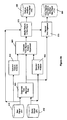
- FIG. 9A Another embodiment, employing the Method 2 described hereinbefore, is shown in FIG. 9A in which a time-aligned New Signal waveform is not generated as a first step. Instead the time-alignment data, obtained as in the embodiment of FIGS. 3 and 8 in a module 920, is used to time distort in a module 960, the measured features of the Guide Signal to the appropriate times in the New Signal. Module 970 makes the time-aligned modifications to the New Signal. An optional time-alignment can be performed on the modified New Signal in the feature modification process module 970 at the same time (combining the processing of modules 970 and 975 into one algorithm), or in a subsequent process module 975 on the feature modified signal. Further details of this approach are given below.
- Ps(Fs) is the estimated pitch of frame Fs of the New Signal.
- W(Fs) is the corresponding frame in the Guide from the warping function.
- This modification function is applied to s(n) at modification module 970 on a frame by frame basis to produce a modified output, s*(n).
- the processing shown in FIG. 9A is generalized as in the description of FIG.8 to allow any signal features to be specified for analysis and modification, but is different in that the modified output s*(n) in store 980 is not time-aligned with the Guide Signal but has instead the timing of the original New Signal s(n).
- Time alignment of the modified output s*(n) to the Guide Signal g(n) can be achieved for pitch modification in a single process where feature modification in module 970 and time alignment in a module 975 are executed simultaneously.
- Descriptions of methods for implementing, for example, simultaneous pitch and time modification are found in references such as J. McAulay and T.
- the normal time alignment function can also be applied to a non-linear editing process in module 975 to create a signal s'*(n), which is a time-aligned version of the feature modified New Signal s*(n).
- FIG. 9B Another embodiment, which performs Method 3, is illustrated in FIG. 9B , in which a time-aligned signal s'(n) in a storage module 982 is created by module 975 using the original time-alignment path created in module 920.
- a New Signal feature contour is produced by module 840 from the unmodified New Signal s(n), and a Guide Signal feature contour is produced by module 850.
- This modification contour is applied in module 972 to the time-aligned New Signal to create the time-aligned and feature modified New Signal, s*'(n), in output storage module 987.
- the Guide Signal can be made up of a series of different individual signals instead of one continuous signal, or multiple Guide Signals (e.g. harmony vocals) can be used to generate multiple vocal parts from a single New Signal.
- features in the New Signal do not have to be measured or input to the New Signal feature adjustment calculations and can simply be modified based on measurements of a feature or features of the Guide Signal.
- An example of this could be the application of reverberation or EQ to the New Signal as functions of those features in the Guide Signal.
- processing modules used in the embodiments described hereinbefore will be software modules when implemented in a system such as the system 100 of FIGS. 1 and 2 but may in alternative implementations be hardware modules or a mixture of hardware and software modules.
- One application of the invention is for creating personalised sound files with a user's voice that can provide, for example, a telephone ringtone on a mobile phone or computer-based telephone system.
- Other examples include replacing any of the ringing or other sounds that can be presented to the caller or call recipient during a phone call or other data exchange.
- Such exchanges can take place via a telephone networks, VOIP (Voice Over Internet Protocol) systems or other message delivery system.
- Further examples include the generation of personalised sound files for any device or system that can use a personalised pre-recorded message.
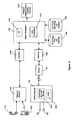
- FIG. 11 illustrates an embodiment of the invention for enabling a user to generate, send and receive such sound files.
- the user initiates a telephone call from landline handset 1110 or mobile phone handset 1120 and through a telecommunications network 1140.
- An appropriate converter 1150 receives the signal from the telecommunication network 1140 and converts it into digital audio signals and operational command tones, and these are processed by a server computer 1160.
- the server computer 1160 can optionally provide interactive Voice Response (IVR) from a module 1165 to give the user choices and feedback on operations.
- IVR Interactive Voice Response
- the server computer 1160 can be implemented in one or more computers and incorporates audio processing modules 1170 for implementing the processes as described in FIG. 3 or 8 or 9A or 9B.
- the computer 1160 accesses a storage module 1180 for storing song audio files and a database for referencing those song files.
- the computer 1160 also stores in a storage module 1185 original and processed user audio recordings and a database for referencing those recordings.
- the server computer 1160 interprets touchtone or other signals to initiate operations. For example, with the telephone keypad in this implementation, the user can instruct the computer 1160 to:
- step (c) the user's voice is recorded in the storage module 1185, processed via the processing module 1170, implementing processing such as that shown in FIG. 3 or 8 or 9A or 9B and the result stored in module 1185.
- the computer 1160 then sends a data message to the recipient's number using a ringtone delivery system 1190 such as "WAP push" system. This data message gives the recipient the information required to download the processed audio to his mobile telephone or other device.
- a user's computer 100 with microphone 159 and speaker 156 is used to access the server computer 1160 directly via the internet 175 or by a telephone call using VOIP software 1135.
- the user can then go through the same procedure as previously described, but listens and records by means of the computer 100 and sends commands entered on the keyboard 125 (not shown) of the computer 100 to the server computer 1160.
- the user can finally specify a mobile phone by its number to receive the created sound file through the delivery system 1190.
- the sound file can also be used in the user's computer 100 or another specified computer (such as a friend's computer) as a ringtone or other identifying sound file in the VOIP system of the specified computer.
- some or all of the processing modules of FIGS. 3 , or 8 , or 9A or 9B can be downloaded to the user's computer 100 as represented by a module 1130.
- a sound file resulting from the use of the module 1130 with or without the assistance of an audio processing module at the server computer 1160 and stored either on the user's computer 100 or the storage module 1185 can be sent via the Internet 175 or telecommunications network 1140 to a requested destination phone or other personal computer.
- the processes can be implemented wholly or in part in phones or any other devices that contain a computer system and memory and means for inputting and outputting the required audio signals.
- video signals (such as music videos) can be provided from the server computer 1160 with the song audio files that the user receives. The user can replay these audio and video signals and make sound recordings as described previously.
- the processed file, mixed with the backing track and synchronized video, is delivered to the designated telephone, personal computer or other device capable of playing an audio/visual file.
- the song audio files are not restricted to songs and can be any sound recording, including speech, sound effects, music or any combination of these.
Landscapes
- Physics & Mathematics (AREA)
- Engineering & Computer Science (AREA)
- Acoustics & Sound (AREA)
- Multimedia (AREA)
- Electrophonic Musical Instruments (AREA)
Priority Applications (1)
| Application Number | Priority Date | Filing Date | Title |
|---|---|---|---|
| PL06709573T PL1849154T3 (pl) | 2005-01-27 | 2006-01-26 | Sposoby i urządzenie do zastosowania w modyfikacji dźwięku |
Applications Claiming Priority (3)
| Application Number | Priority Date | Filing Date | Title |
|---|---|---|---|
| US64755505P | 2005-01-27 | 2005-01-27 | |
| GB0501744A GB2422755A (en) | 2005-01-27 | 2005-01-27 | Audio signal processing |
| PCT/GB2006/000262 WO2006079813A1 (en) | 2005-01-27 | 2006-01-26 | Methods and apparatus for use in sound modification |
Publications (2)
| Publication Number | Publication Date |
|---|---|
| EP1849154A1 EP1849154A1 (en) | 2007-10-31 |
| EP1849154B1 true EP1849154B1 (en) | 2010-12-15 |
Family
ID=36120266
Family Applications (1)
| Application Number | Title | Priority Date | Filing Date |
|---|---|---|---|
| EP06709573A Active EP1849154B1 (en) | 2005-01-27 | 2006-01-26 | Methods and apparatus for use in sound modification |
Country Status (4)
| Country | Link |
|---|---|
| EP (1) | EP1849154B1 (enExample) |
| JP (1) | JP5143569B2 (enExample) |
| PL (1) | PL1849154T3 (enExample) |
| WO (1) | WO2006079813A1 (enExample) |
Cited By (1)
| Publication number | Priority date | Publication date | Assignee | Title |
|---|---|---|---|---|
| US9607594B2 (en) | 2013-12-20 | 2017-03-28 | Samsung Electronics Co., Ltd. | Multimedia apparatus, music composing method thereof, and song correcting method thereof |
Families Citing this family (17)
| Publication number | Priority date | Publication date | Assignee | Title |
|---|---|---|---|---|
| JP4322283B2 (ja) | 2007-02-26 | 2009-08-26 | 独立行政法人産業技術総合研究所 | 演奏判定装置およびプログラム |
| JP5135931B2 (ja) * | 2007-07-17 | 2013-02-06 | ヤマハ株式会社 | 楽曲加工装置およびプログラム |
| US9159325B2 (en) * | 2007-12-31 | 2015-10-13 | Adobe Systems Incorporated | Pitch shifting frequencies |
| JP5141397B2 (ja) | 2008-06-24 | 2013-02-13 | ヤマハ株式会社 | 音声処理装置およびプログラム |
| KR101360456B1 (ko) | 2008-07-11 | 2014-02-07 | 프라운호퍼 게젤샤프트 쭈르 푀르데룽 데어 안겐반텐 포르슝 에. 베. | 시간 워프 활성 신호의 제공 및 이를 이용한 오디오 신호의 인코딩 |
| MY154452A (en) | 2008-07-11 | 2015-06-15 | Fraunhofer Ges Forschung | An apparatus and a method for decoding an encoded audio signal |
| US9601127B2 (en) | 2010-04-12 | 2017-03-21 | Smule, Inc. | Social music system and method with continuous, real-time pitch correction of vocal performance and dry vocal capture for subsequent re-rendering based on selectively applicable vocal effect(s) schedule(s) |
| US10930256B2 (en) | 2010-04-12 | 2021-02-23 | Smule, Inc. | Social music system and method with continuous, real-time pitch correction of vocal performance and dry vocal capture for subsequent re-rendering based on selectively applicable vocal effect(s) schedule(s) |
| EP2626856B1 (en) | 2010-10-06 | 2020-07-29 | Panasonic Corporation | Encoding device, decoding device, encoding method, and decoding method |
| JP6003083B2 (ja) * | 2012-02-27 | 2016-10-05 | ソニー株式会社 | 信号処理装置、信号処理方法、およびプログラム、電子機器、並びに、信号処理システムおよび信号処理システムの信号処理方法 |
| WO2014025819A1 (en) * | 2012-08-07 | 2014-02-13 | Smule, Inc. | Social music system and method with continuous, real-time pitch correction of vocal performance and dry vocal capture for subsequent re-rendering based on selectively applicable vocal effect(s) schedule(s) |
| CN107093991B (zh) * | 2013-03-26 | 2020-10-09 | 杜比实验室特许公司 | 基于目标响度的响度归一化方法和设备 |
| CN105869621B (zh) * | 2016-05-20 | 2019-10-25 | 广州华多网络科技有限公司 | 音频合成装置及其音频合成的方法 |
| WO2019035835A1 (en) * | 2017-08-17 | 2019-02-21 | Nuance Communications, Inc. | DETECTION WITH LOW SPEECH COMPLEXITY AND ESTIMATED HEIGHT |
| CN109841225B (zh) * | 2019-01-28 | 2021-04-30 | 北京易捷胜科技有限公司 | 声音替换方法、电子设备和存储介质 |
| CN110769309B (zh) * | 2019-11-04 | 2023-03-31 | 北京字节跳动网络技术有限公司 | 用于展示音乐点的方法、装置、电子设备和介质 |
| US11475867B2 (en) * | 2019-12-27 | 2022-10-18 | Spotify Ab | Method, system, and computer-readable medium for creating song mashups |
Family Cites Families (10)
| Publication number | Priority date | Publication date | Assignee | Title |
|---|---|---|---|---|
| CA1204855A (en) * | 1982-03-23 | 1986-05-20 | Phillip J. Bloom | Method and apparatus for use in processing signals |
| JPH0772881A (ja) * | 1993-09-06 | 1995-03-17 | Matsushita Electric Ind Co Ltd | カラオケ装置 |
| JP2904045B2 (ja) * | 1995-02-27 | 1999-06-14 | ヤマハ株式会社 | カラオケ装置 |
| JP3102335B2 (ja) * | 1996-01-18 | 2000-10-23 | ヤマハ株式会社 | フォルマント変換装置およびカラオケ装置 |
| GB9711339D0 (en) * | 1997-06-02 | 1997-07-30 | Isis Innovation | Method and apparatus for reproducing a recorded voice with alternative performance attributes and temporal properties |
| US6836761B1 (en) * | 1999-10-21 | 2004-12-28 | Yamaha Corporation | Voice converter for assimilation by frame synthesis with temporal alignment |
| JP2001117599A (ja) * | 1999-10-21 | 2001-04-27 | Yamaha Corp | 音声処理装置およびカラオケ装置 |
| JP3595286B2 (ja) * | 2001-07-31 | 2004-12-02 | 株式会社第一興商 | ピッチシフター付きカラオケ装置 |
| FR2843479B1 (fr) * | 2002-08-07 | 2004-10-22 | Smart Inf Sa | Procede de calibrage d'audio-intonation |
| JP2004287350A (ja) * | 2003-03-25 | 2004-10-14 | Casio Comput Co Ltd | 音声変換装置、音声効果付与装置、及びプログラム |
-
2006
- 2006-01-26 JP JP2007552713A patent/JP5143569B2/ja active Active
- 2006-01-26 PL PL06709573T patent/PL1849154T3/pl unknown
- 2006-01-26 EP EP06709573A patent/EP1849154B1/en active Active
- 2006-01-26 WO PCT/GB2006/000262 patent/WO2006079813A1/en not_active Ceased
Cited By (1)
| Publication number | Priority date | Publication date | Assignee | Title |
|---|---|---|---|---|
| US9607594B2 (en) | 2013-12-20 | 2017-03-28 | Samsung Electronics Co., Ltd. | Multimedia apparatus, music composing method thereof, and song correcting method thereof |
Also Published As
| Publication number | Publication date |
|---|---|
| JP5143569B2 (ja) | 2013-02-13 |
| WO2006079813A1 (en) | 2006-08-03 |
| JP2008529078A (ja) | 2008-07-31 |
| PL1849154T3 (pl) | 2011-05-31 |
| EP1849154A1 (en) | 2007-10-31 |
Similar Documents
| Publication | Publication Date | Title |
|---|---|---|
| US7825321B2 (en) | Methods and apparatus for use in sound modification comparing time alignment data from sampled audio signals | |
| EP1849154B1 (en) | Methods and apparatus for use in sound modification | |
| JP6083764B2 (ja) | 歌声合成システム及び歌声合成方法 | |
| JP6610714B1 (ja) | 電子楽器、電子楽器の制御方法、及びプログラム | |
| JP6610715B1 (ja) | 電子楽器、電子楽器の制御方法、及びプログラム | |
| US8244546B2 (en) | Singing synthesis parameter data estimation system | |
| US9847078B2 (en) | Music performance system and method thereof | |
| US10008193B1 (en) | Method and system for speech-to-singing voice conversion | |
| Umbert et al. | Expression control in singing voice synthesis: Features, approaches, evaluation, and challenges | |
| JP2008015195A (ja) | 楽曲練習支援装置 | |
| JP2012037722A (ja) | 音合成用データ生成装置およびピッチ軌跡生成装置 | |
| JP6737320B2 (ja) | 音響処理方法、音響処理システムおよびプログラム | |
| JP2003241757A (ja) | 波形生成装置及び方法 | |
| JP2016161919A (ja) | 音声合成装置 | |
| JP2010014913A (ja) | 声質変換音声生成装置および声質変換音声生成システム | |
| CN101111884B (zh) | 用于声学特征的同步修改的方法和装置 | |
| JP4430174B2 (ja) | 音声変換装置及び音声変換方法 | |
| JP5106437B2 (ja) | カラオケ装置及びその制御方法並びにその制御プログラム | |
| Alexandraki | Real-time machine listening and segmental re-synthesis for networked music performance | |
| JP2000010597A (ja) | 音声変換装置及び音声変換方法 | |
| EP0986807A1 (en) | Method and apparatus for reproducing a recorded voice with alternative performance attributes and temporal properties | |
| JP2022065554A (ja) | 音声合成方法およびプログラム | |
| Wang et al. | Mandarin singing voice synthesis based on harmonic plus noise model and singing expression analysis | |
| Bonada et al. | Improvements to a sample-concatenation based singing voice synthesizer | |
| Umbert Morist et al. | Expression control in singing voice synthesis: features, approaches, evaluation, and challenges |
Legal Events
| Date | Code | Title | Description |
|---|---|---|---|
| PUAI | Public reference made under article 153(3) epc to a published international application that has entered the european phase |
Free format text: ORIGINAL CODE: 0009012 |
|
| 17P | Request for examination filed |
Effective date: 20070821 |
|
| AK | Designated contracting states |
Kind code of ref document: A1 Designated state(s): AT BE BG CH CY CZ DE DK EE ES FI FR GB GR HU IE IS IT LI LT LU LV MC NL PL PT RO SE SI SK TR |
|
| DAX | Request for extension of the european patent (deleted) | ||
| 17Q | First examination report despatched |
Effective date: 20091106 |
|
| GRAP | Despatch of communication of intention to grant a patent |
Free format text: ORIGINAL CODE: EPIDOSNIGR1 |
|
| GRAS | Grant fee paid |
Free format text: ORIGINAL CODE: EPIDOSNIGR3 |
|
| GRAA | (expected) grant |
Free format text: ORIGINAL CODE: 0009210 |
|
| AK | Designated contracting states |
Kind code of ref document: B1 Designated state(s): AT BE BG CH CY CZ DE DK EE ES FI FR GB GR HU IE IS IT LI LT LU LV MC NL PL PT RO SE SI SK TR |
|
| REG | Reference to a national code |
Ref country code: CH Ref legal event code: EP Ref country code: GB Ref legal event code: FG4D |
|
| REG | Reference to a national code |
Ref country code: IE Ref legal event code: FG4D |
|
| REF | Corresponds to: |
Ref document number: 602006018867 Country of ref document: DE Date of ref document: 20110127 Kind code of ref document: P |
|
| REG | Reference to a national code |
Ref country code: NL Ref legal event code: VDEP Effective date: 20101215 |
|
| REG | Reference to a national code |
Ref country code: ES Ref legal event code: FG2A Ref document number: 2356476 Country of ref document: ES Kind code of ref document: T3 Effective date: 20110408 |
|
| PG25 | Lapsed in a contracting state [announced via postgrant information from national office to epo] |
Ref country code: LT Free format text: LAPSE BECAUSE OF FAILURE TO SUBMIT A TRANSLATION OF THE DESCRIPTION OR TO PAY THE FEE WITHIN THE PRESCRIBED TIME-LIMIT Effective date: 20101215 |
|
| LTIE | Lt: invalidation of european patent or patent extension |
Effective date: 20101215 |
|
| PG25 | Lapsed in a contracting state [announced via postgrant information from national office to epo] |
Ref country code: SI Free format text: LAPSE BECAUSE OF FAILURE TO SUBMIT A TRANSLATION OF THE DESCRIPTION OR TO PAY THE FEE WITHIN THE PRESCRIBED TIME-LIMIT Effective date: 20101215 Ref country code: CY Free format text: LAPSE BECAUSE OF FAILURE TO SUBMIT A TRANSLATION OF THE DESCRIPTION OR TO PAY THE FEE WITHIN THE PRESCRIBED TIME-LIMIT Effective date: 20101215 Ref country code: FI Free format text: LAPSE BECAUSE OF FAILURE TO SUBMIT A TRANSLATION OF THE DESCRIPTION OR TO PAY THE FEE WITHIN THE PRESCRIBED TIME-LIMIT Effective date: 20101215 Ref country code: BG Free format text: LAPSE BECAUSE OF FAILURE TO SUBMIT A TRANSLATION OF THE DESCRIPTION OR TO PAY THE FEE WITHIN THE PRESCRIBED TIME-LIMIT Effective date: 20110315 Ref country code: LV Free format text: LAPSE BECAUSE OF FAILURE TO SUBMIT A TRANSLATION OF THE DESCRIPTION OR TO PAY THE FEE WITHIN THE PRESCRIBED TIME-LIMIT Effective date: 20101215 Ref country code: NL Free format text: LAPSE BECAUSE OF FAILURE TO SUBMIT A TRANSLATION OF THE DESCRIPTION OR TO PAY THE FEE WITHIN THE PRESCRIBED TIME-LIMIT Effective date: 20101215 Ref country code: AT Free format text: LAPSE BECAUSE OF FAILURE TO SUBMIT A TRANSLATION OF THE DESCRIPTION OR TO PAY THE FEE WITHIN THE PRESCRIBED TIME-LIMIT Effective date: 20101215 Ref country code: SE Free format text: LAPSE BECAUSE OF FAILURE TO SUBMIT A TRANSLATION OF THE DESCRIPTION OR TO PAY THE FEE WITHIN THE PRESCRIBED TIME-LIMIT Effective date: 20101215 |
|
| REG | Reference to a national code |
Ref country code: PL Ref legal event code: T3 |
|
| PG25 | Lapsed in a contracting state [announced via postgrant information from national office to epo] |
Ref country code: PT Free format text: LAPSE BECAUSE OF FAILURE TO SUBMIT A TRANSLATION OF THE DESCRIPTION OR TO PAY THE FEE WITHIN THE PRESCRIBED TIME-LIMIT Effective date: 20110415 Ref country code: EE Free format text: LAPSE BECAUSE OF FAILURE TO SUBMIT A TRANSLATION OF THE DESCRIPTION OR TO PAY THE FEE WITHIN THE PRESCRIBED TIME-LIMIT Effective date: 20101215 Ref country code: CZ Free format text: LAPSE BECAUSE OF FAILURE TO SUBMIT A TRANSLATION OF THE DESCRIPTION OR TO PAY THE FEE WITHIN THE PRESCRIBED TIME-LIMIT Effective date: 20101215 Ref country code: GR Free format text: LAPSE BECAUSE OF FAILURE TO SUBMIT A TRANSLATION OF THE DESCRIPTION OR TO PAY THE FEE WITHIN THE PRESCRIBED TIME-LIMIT Effective date: 20110316 Ref country code: IS Free format text: LAPSE BECAUSE OF FAILURE TO SUBMIT A TRANSLATION OF THE DESCRIPTION OR TO PAY THE FEE WITHIN THE PRESCRIBED TIME-LIMIT Effective date: 20110415 Ref country code: BE Free format text: LAPSE BECAUSE OF FAILURE TO SUBMIT A TRANSLATION OF THE DESCRIPTION OR TO PAY THE FEE WITHIN THE PRESCRIBED TIME-LIMIT Effective date: 20101215 |
|
| PG25 | Lapsed in a contracting state [announced via postgrant information from national office to epo] |
Ref country code: MC Free format text: LAPSE BECAUSE OF NON-PAYMENT OF DUE FEES Effective date: 20110131 Ref country code: SK Free format text: LAPSE BECAUSE OF FAILURE TO SUBMIT A TRANSLATION OF THE DESCRIPTION OR TO PAY THE FEE WITHIN THE PRESCRIBED TIME-LIMIT Effective date: 20101215 Ref country code: RO Free format text: LAPSE BECAUSE OF FAILURE TO SUBMIT A TRANSLATION OF THE DESCRIPTION OR TO PAY THE FEE WITHIN THE PRESCRIBED TIME-LIMIT Effective date: 20101215 |
|
| REG | Reference to a national code |
Ref country code: CH Ref legal event code: PL |
|
| PLBE | No opposition filed within time limit |
Free format text: ORIGINAL CODE: 0009261 |
|
| STAA | Information on the status of an ep patent application or granted ep patent |
Free format text: STATUS: NO OPPOSITION FILED WITHIN TIME LIMIT |
|
| PG25 | Lapsed in a contracting state [announced via postgrant information from national office to epo] |
Ref country code: DK Free format text: LAPSE BECAUSE OF FAILURE TO SUBMIT A TRANSLATION OF THE DESCRIPTION OR TO PAY THE FEE WITHIN THE PRESCRIBED TIME-LIMIT Effective date: 20101215 Ref country code: CH Free format text: LAPSE BECAUSE OF NON-PAYMENT OF DUE FEES Effective date: 20110131 Ref country code: LI Free format text: LAPSE BECAUSE OF NON-PAYMENT OF DUE FEES Effective date: 20110131 |
|
| 26N | No opposition filed |
Effective date: 20110916 |
|
| REG | Reference to a national code |
Ref country code: DE Ref legal event code: R097 Ref document number: 602006018867 Country of ref document: DE Effective date: 20110916 |
|
| PG25 | Lapsed in a contracting state [announced via postgrant information from national office to epo] |
Ref country code: LU Free format text: LAPSE BECAUSE OF NON-PAYMENT OF DUE FEES Effective date: 20110126 |
|
| PG25 | Lapsed in a contracting state [announced via postgrant information from national office to epo] |
Ref country code: HU Free format text: LAPSE BECAUSE OF FAILURE TO SUBMIT A TRANSLATION OF THE DESCRIPTION OR TO PAY THE FEE WITHIN THE PRESCRIBED TIME-LIMIT Effective date: 20101215 |
|
| REG | Reference to a national code |
Ref country code: FR Ref legal event code: PLFP Year of fee payment: 11 |
|
| REG | Reference to a national code |
Ref country code: FR Ref legal event code: PLFP Year of fee payment: 12 |
|
| REG | Reference to a national code |
Ref country code: FR Ref legal event code: PLFP Year of fee payment: 13 |
|
| PGFP | Annual fee paid to national office [announced via postgrant information from national office to epo] |
Ref country code: PL Payment date: 20241230 Year of fee payment: 20 |
|
| PGFP | Annual fee paid to national office [announced via postgrant information from national office to epo] |
Ref country code: DE Payment date: 20250121 Year of fee payment: 20 |
|
| PGFP | Annual fee paid to national office [announced via postgrant information from national office to epo] |
Ref country code: ES Payment date: 20250203 Year of fee payment: 20 |
|
| PGFP | Annual fee paid to national office [announced via postgrant information from national office to epo] |
Ref country code: IE Payment date: 20250116 Year of fee payment: 20 |
|
| PGFP | Annual fee paid to national office [announced via postgrant information from national office to epo] |
Ref country code: FR Payment date: 20250117 Year of fee payment: 20 |
|
| PGFP | Annual fee paid to national office [announced via postgrant information from national office to epo] |
Ref country code: IT Payment date: 20250123 Year of fee payment: 20 Ref country code: GB Payment date: 20250121 Year of fee payment: 20 |
|
| PGFP | Annual fee paid to national office [announced via postgrant information from national office to epo] |
Ref country code: TR Payment date: 20250106 Year of fee payment: 20 |