EP1848876B1 - Procede pour augmenter la duree de vie en fatigue de l'emplanture d'une aube de turbomachine - Google Patents
Procede pour augmenter la duree de vie en fatigue de l'emplanture d'une aube de turbomachine Download PDFInfo
- Publication number
- EP1848876B1 EP1848876B1 EP06708140A EP06708140A EP1848876B1 EP 1848876 B1 EP1848876 B1 EP 1848876B1 EP 06708140 A EP06708140 A EP 06708140A EP 06708140 A EP06708140 A EP 06708140A EP 1848876 B1 EP1848876 B1 EP 1848876B1
- Authority
- EP
- European Patent Office
- Prior art keywords
- blade
- slot
- stress field
- impressing
- blade root
- Prior art date
- Legal status (The legal status is an assumption and is not a legal conclusion. Google has not performed a legal analysis and makes no representation as to the accuracy of the status listed.)
- Not-in-force
Links
Images

Classifications
-
- F—MECHANICAL ENGINEERING; LIGHTING; HEATING; WEAPONS; BLASTING
- F01—MACHINES OR ENGINES IN GENERAL; ENGINE PLANTS IN GENERAL; STEAM ENGINES
- F01D—NON-POSITIVE DISPLACEMENT MACHINES OR ENGINES, e.g. STEAM TURBINES
- F01D5/00—Blades; Blade-carrying members; Heating, heat-insulating, cooling or antivibration means on the blades or the members
- F01D5/12—Blades
- F01D5/14—Form or construction
-
- B—PERFORMING OPERATIONS; TRANSPORTING
- B23—MACHINE TOOLS; METAL-WORKING NOT OTHERWISE PROVIDED FOR
- B23P—METAL-WORKING NOT OTHERWISE PROVIDED FOR; COMBINED OPERATIONS; UNIVERSAL MACHINE TOOLS
- B23P9/00—Treating or finishing surfaces mechanically, with or without calibrating, primarily to resist wear or impact, e.g. smoothing or roughening turbine blades or bearings; Features of such surfaces not otherwise provided for, their treatment being unspecified
- B23P9/02—Treating or finishing by applying pressure, e.g. knurling
-
- F—MECHANICAL ENGINEERING; LIGHTING; HEATING; WEAPONS; BLASTING
- F01—MACHINES OR ENGINES IN GENERAL; ENGINE PLANTS IN GENERAL; STEAM ENGINES
- F01D—NON-POSITIVE DISPLACEMENT MACHINES OR ENGINES, e.g. STEAM TURBINES
- F01D5/00—Blades; Blade-carrying members; Heating, heat-insulating, cooling or antivibration means on the blades or the members
- F01D5/30—Fixing blades to rotors; Blade roots ; Blade spacers
-
- F—MECHANICAL ENGINEERING; LIGHTING; HEATING; WEAPONS; BLASTING
- F05—INDEXING SCHEMES RELATING TO ENGINES OR PUMPS IN VARIOUS SUBCLASSES OF CLASSES F01-F04
- F05D—INDEXING SCHEME FOR ASPECTS RELATING TO NON-POSITIVE-DISPLACEMENT MACHINES OR ENGINES, GAS-TURBINES OR JET-PROPULSION PLANTS
- F05D2270/00—Control
- F05D2270/01—Purpose of the control system
- F05D2270/11—Purpose of the control system to prolong engine life
- F05D2270/114—Purpose of the control system to prolong engine life by limiting mechanical stresses
-
- Y—GENERAL TAGGING OF NEW TECHNOLOGICAL DEVELOPMENTS; GENERAL TAGGING OF CROSS-SECTIONAL TECHNOLOGIES SPANNING OVER SEVERAL SECTIONS OF THE IPC; TECHNICAL SUBJECTS COVERED BY FORMER USPC CROSS-REFERENCE ART COLLECTIONS [XRACs] AND DIGESTS
- Y10—TECHNICAL SUBJECTS COVERED BY FORMER USPC
- Y10T—TECHNICAL SUBJECTS COVERED BY FORMER US CLASSIFICATION
- Y10T29/00—Metal working
- Y10T29/49—Method of mechanical manufacture
- Y10T29/49316—Impeller making
- Y10T29/49318—Repairing or disassembling
-
- Y—GENERAL TAGGING OF NEW TECHNOLOGICAL DEVELOPMENTS; GENERAL TAGGING OF CROSS-SECTIONAL TECHNOLOGIES SPANNING OVER SEVERAL SECTIONS OF THE IPC; TECHNICAL SUBJECTS COVERED BY FORMER USPC CROSS-REFERENCE ART COLLECTIONS [XRACs] AND DIGESTS
- Y10—TECHNICAL SUBJECTS COVERED BY FORMER USPC
- Y10T—TECHNICAL SUBJECTS COVERED BY FORMER US CLASSIFICATION
- Y10T29/00—Metal working
- Y10T29/49—Method of mechanical manufacture
- Y10T29/49316—Impeller making
- Y10T29/49336—Blade making
-
- Y—GENERAL TAGGING OF NEW TECHNOLOGICAL DEVELOPMENTS; GENERAL TAGGING OF CROSS-SECTIONAL TECHNOLOGIES SPANNING OVER SEVERAL SECTIONS OF THE IPC; TECHNICAL SUBJECTS COVERED BY FORMER USPC CROSS-REFERENCE ART COLLECTIONS [XRACs] AND DIGESTS
- Y10—TECHNICAL SUBJECTS COVERED BY FORMER USPC
- Y10T—TECHNICAL SUBJECTS COVERED BY FORMER US CLASSIFICATION
- Y10T29/00—Metal working
- Y10T29/49—Method of mechanical manufacture
- Y10T29/49718—Repairing
- Y10T29/49721—Repairing with disassembling
- Y10T29/49723—Repairing with disassembling including reconditioning of part
- Y10T29/49725—Repairing with disassembling including reconditioning of part by shaping
-
- Y—GENERAL TAGGING OF NEW TECHNOLOGICAL DEVELOPMENTS; GENERAL TAGGING OF CROSS-SECTIONAL TECHNOLOGIES SPANNING OVER SEVERAL SECTIONS OF THE IPC; TECHNICAL SUBJECTS COVERED BY FORMER USPC CROSS-REFERENCE ART COLLECTIONS [XRACs] AND DIGESTS
- Y10—TECHNICAL SUBJECTS COVERED BY FORMER USPC
- Y10T—TECHNICAL SUBJECTS COVERED BY FORMER US CLASSIFICATION
- Y10T29/00—Metal working
- Y10T29/49—Method of mechanical manufacture
- Y10T29/49718—Repairing
- Y10T29/49748—Repairing by shaping, e.g., bending, extruding, turning, etc.
Definitions
- the invention relates to a method for increasing the fatigue life of a blade root of a turbomachinery blade.
- turbomachinery blades are subjected to high mechanical loads during operation of the turbomachine. This applies in particular to the blade roots of rotor blades, via which the flow-induced forces acting on the respective blade during operation and the centrifugal forces acting on the respective blade are discharged into the adjacent shaft components. In addition to mechanical loads, turbine blades in particular also suffer from high thermal loads.
- blade root shapes are the hammer-foot design and the Christmas tree design.
- the mostly triangular-shaped blade root at least one groove is arranged on each of the two free sides of the triangle for engaging behind in an adjacent component.
- the component adjacent to the blade root in the assembly arrangement of the turbomachine has, for the positive reception of the blade root, a recess corresponding to the contour of the blade root.
- webs or thickenings are arranged, which engage in the assembly arrangement in the grooves of the blade root.
- the blade root of the blade can thus be positively inserted into the recess of the component and is fixed by the engaging behind in the grooves webs or thickening in the component.
- From the DE 43 09 176 A 1 shows a method with which the material areas of the fastening grooves on turbine blade roots are subject to multiple local compressive stress entry in order to obtain increased damage resistance to vibration crack corrosion in these areas.
- the groove bottom of the fastening grooves is repeatedly contacted with a pressurized pressure with a spherical tool, whereby internal compressive stresses are induced within the groove bottom by way of elastic and plastic deformations.
- the spherical tool is preferably formed as a roller and is inserted along the mounting grooves and rolled along this.
- the invention is therefore based on the object of specifying a method of the type mentioned above with which it should be possible to increase the fatigue life of a blade root of a turbomachinery blade with a reduced compared to the prior art process cost.
- the blade feet considered by the invention for example, designed as a hammer foot, respectively, as known from the prior art, equipped with a groove.
- the method comprises, likewise to the prior art, imparting a mechanical stress field to the notch root of the groove in at least one section of the groove, wherein the impressed mechanical stress field causes a plastic deformation of the notch root.
- Notched base denotes the material layer of the blade root adjoining the surface of the groove.
- the applied in the notch base of the groove mechanical stress field is then moved in Nutlhacksraum the groove, whereby in each swept portion of the groove, a plastic deformation of the notch base is effected.
- the impressed mechanical stress field is then removed again, wherein within the regions of the groove, in which the mechanical stress field was impressed, residual compressive stresses remain in the notch bottom of the groove.
- the impressed mechanical stress field is moved along the entire length of the groove, so that remain after the removal of the impressed mechanical stress field over the entire length of the groove residual compressive stresses in the notch.
- a residual compressive stress field is induced on the notch bottom of the groove.
- this residual compressive residual stress field is superimposed by the operational induced stresses resulting from the forces acting on the blade.
- the in operation on the Kerbground acting tensile loads are at least partially or completely compensated by the remaining compressive stress field, so that sets a considerably lower tension mean stress in the notch base.
- pressure loads acting on the notch base during operation add up to the compressive residual stresses of the compressive residual stress field.
- pressure loads have only a small influence on the fatigue of the material of the blade root. Overall, this thus leads to a lower fatigue of the blade root due to alternating loads of Nutut under the same load situation.
- the turbomachine blade can thus be used over a longer period of operation. This leads to lower maintenance costs and increased service life of the turbomachine.
- the press-in profile is trapezoidal in shape with a broad trapezoidal base side, a narrow trapezoidal base side and two trapezoidal limbs.
- the trapeze is stretched so that in a press-fitting arrangement, the narrow trapezoid base side penetrates furthest into the groove, but does not touch the notch bottom of the groove.
- the wide trapezoidal side is designed so wide that the trapezoidal legs, which are formed as connecting surfaces between the wide and the narrow trapezoidal base side, come to rest on the groove shoulders of the groove.
- the compressive residual stress field is chosen so that the load cycles occur symmetrically during operation. As a result, the usable number of cycles is ultimately increased significantly. At the same time, in addition, as a side effect, the fatigue strength is increased.
- the impressed in the notch base of the groove mechanical stress field is moved by rolling or rolling the press tool along the groove.
- the blade root is moved in synchronism with the rolling process of the press-in tool and adjusted thereto translationally.
- the press-in tool can be designed as a press-in wheel.
- a defined press-in force can be generated in a simple manner and moved along the entire groove.
- the defined press-in force is expediently determined as a function of the maximum alternating or oscillatory stress of the blade root occurring during operation of the blade, of the material of the blade root and of the contour of the press-fitting tool.
- a blade root made of a nickel-based alloy to deform the notch base of the groove by the impressed stress field in a range between 5% and 12% plastic strain.
- a plastic elongation of the material of the notch base within this preferred range forms after completion of the press-in a sufficiently high compressive residual stress field in order to compensate for tensile stresses occurring during operation of the blade sufficiently.
- an overstretching of the material of the notch base is avoided as a result of the Einpressvorgangs.
- the inventive method is preferably used in the production of blades for turbomachinery or turbo groups, such as gas or steam turbines, or the production of blades for other uses. As a result, both the overall service life of the blade to be produced and the operating time up to an inspection overhaul of the blade can be increased.
- the method according to the invention can also be applied to a blade which has already been used during operation and is to be overhauled.
- it is often possible to increase both the remaining service life of the scoop to be overhauled and the duration of time until the next inspection overhaul of the scoop.
- It has proved to be very expedient here that only very small changes in the geometry of the blade root are brought about by the method according to the invention for increasing the alternating strength of a blade. Reworking on the overhauling blade after performing the method according to the invention are therefore not required.
- a turbomachinery blade having a blade root with increased crush resistance.
- the blade root comprises at least one groove arranged in the blade root for engagement in a shaft component or a housing component of a turbomachine.
- the blade root is machined according to the method according to the invention described above.
- turbomachine blade according to the invention compared with the turbomachinery blades known from the prior art correspond to the embodiments made above with reference to the method executed according to the invention.
- the turbomachine blade is designed as a rotor blade of a turbomachine, preferably as a compressor rotor blade of a turbomachine.
- Rotor blades usually have high centrifugal forces during operation of the turbomachine.
- high-frequency vibrations for example, by the start-up and shutdown of the turbomachine and by load changes of the turbomachine additionally have high low-frequency alternating stresses on the blade roots of the rotor blades.
- the application of the method according to the invention leads to a considerable reduction of the effective stress load of the blade root and thus to an extension of the service life of the blades.
- the blade root of the turbomachine blade is suitably made of a nickel-base alloy or a titanium alloy.
- the groove arranged in the blade root is preferably designed with a semicircular or approximately semicircular contour.
- a semicircular or approximately semicircular contour of the groove a surface load of the notch base is ensured with a largely continuous course without sudden change in the surface load. Accordingly, the voltage curve in Kerbground is continuous and without sudden change.
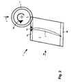
- FIG. 1 a compressor rotor blade 1 of a gas turbine is shown schematically.
- the blade 1 in each case comprises an airfoil 2 and a blade root 3 adjoining the airfoil blade 2 on the blade side longitudinal direction.
- the blade root 3 serves to anchor the relevant rotor blade 1 in a shaft component of the gas turbine.
- the respective semicircular grooves 4a, 4b extend perpendicularly or substantially perpendicularly to the blade airfoil longitudinal direction 2SL in the width direction of the respective blade root 3.
- the shaft components have recesses corresponding to the contour of the blade roots.
- Fixierstege are further arranged, which engage in the grooves 4a, 4b of the blade roots 3 and fix the blade roots 3 in each case by means of engaging behind positive engagement in blade longitudinal direction 2SL.
- the centrifugal forces acting on the respective blade during the operation of the blades due to the rotation of the rotor can be initiated in a favorable manner from the blade into the respective shaft component.
- Due to the semicircular contour of the grooves 4a and 4b and the engaging in the grooves Fixierstege results in a steady voltage curve over the groove contour without sudden changes in the voltage curve.
- the blades 1 are usually inserted laterally into the recesses of the shaft components.
- the blade roots are conventionally sand-blasted or shot-peened and / or coated and / or diffusion-hardened. Such a treatment leads to a higher surface hardness, so that the surface can be subjected to a higher static load.
- the lifetime of the blades is often limited today by the maximum permissible change stability of the blade root.
- the blade When reaching the maximum permissible number of oscillations, the blade must be renewed or at least overhauled. In the operation of the blades occur due to the superpositions of static and alternating or oscillating as well as thermal loads but also total loads that exceed the maximum permissible material load. As a result, as well as when the maximum permissible oscillation number is exceeded, cracking may occur, especially in the root of the blade, which necessitates replacement of the blade concerned.
- the invention aims to remedy this situation.
- the mean tensile stresses acting on a blade root during operation can be reduced, whereby the fatigue life of the blade root is increased.
- a mechanical stress field is impressed, wherein the impressed mechanical stress field, a plastic deformation of the notch bases 5a, 5b of the grooves 4a and 4b in the acted upon Section causes.
- the impressed mechanical stress field is then moved in the groove longitudinal direction of the respective groove 4a and 4b. If the groove 4a or 4b processed in this way over its entire length, the impressed mechanical stress field is removed again, but remain in the notch base 5a and 5b of the groove 4a and 4b residual compressive stresses.
- FIG. 1 In addition to the blade 1, a press-in tool is shown, which is suitable for carrying out the method according to the invention.
- the press-in tool is designed here as a press-in wheel 61, which is pressed circumferentially into the respective groove 4a and 4b of the relevant blade root 2 for generating the mechanical stress field.
- the press-in profile 71 of in FIG. 1 shown Einpressrades 61 is trapezoidal and comprises a broad trapezoidal base side 71-3, a narrow trapezoidal base side 71-4 and two trapezoidal legs 7I-1 and 7I-2.
- the free angles 7I-1W and 7I-2W between the trapezoidal legs 7I-1 and 7i-2 and the narrow trapezoidal base side 71-4 is preferably about 60 ° to 80 °.
- FIG. 2 clarifies For this the movements of the in FIG. 1 While the press-in 6 rotates at constant effective direction 8 of the press-in force about its axis of rotation (see rotary arrow 9), the blade 1 together with blade root 3 in the groove longitudinal direction NL according to the movement arrow 9b in FIG. 2 moved translationally. Translation of the blade 1 and rotation of the press-in wheel 6 are in this case coordinated so that no slip of the press-in wheel 6 occurs.
- a blade root machined in this way according to the method according to the invention has a higher fatigue life and, in addition, a higher fatigue strength than the conventionally machined blade root due to the induced compressive residual stress field.
- the blade can accordingly remain in operation longer without having to be replaced or overhauled.
- the blade root processed according to the invention can be loaded with a higher alternating stress.
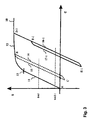
- FIG. 3 illustrates how alternating loads or vibration loads that occur during operation of the blade in the stress-strain diagram of the material of the notch base 5a and 5b of the groove 4a and 4b of the blade root 2 from FIG. 1 represent.
- stress-strain curve 10 here is the expansion behavior of the material of the notch base 5a and 5b of the blade root 2 under tensile load again.
- the material is first deformed purely elastically along the strain curve 11. This elastic deformation is linear to the applied tensile stress s. From a certain load limit 12 occurs in addition to the elastic deformation of the material and a plastic deformation of the material.
- the stress-strain curve 10 runs from here nonlinear and flatter (stress-strain curve in area 13).
- the result for the same cyclic loading of the material of the notch base is a lower mean stress value s m2-1 in FIG. 3 ,
- the notch bases 5a and 5b of the grooves 4a and 4b of the respective blade root 2 is impressed by pressing in the press-in wheel 6I a mechanical stress field, whereby in the respective notch base 5a and 5b, a plastic deformation is effected.
- a press tool in FIG. 1 Pressing in 6I used, so sets in the material of the notch base 5a and 5b during the pressing of the press-in 61, a stress-strain state, the point D-1 of the stress-strain curve 10 in FIG. 3 equivalent.
- a tensile stress according to the item D-1 is due to the fact that the press-in 6I with the trapezoidal limbs 7I-1 and 7I-2 at the groove shoulders 5a1 and 5a2 or 5b1 and 5b2 of the grooves 4a and 4b comes to rest and the grooves be spread by the thus introduced pressing force.
- the hereby caused in the relevant groove Tensile stress leads to a plastic tensile deformation of the notch base 5a or 5b according to the point D-1 in Figure 4.
- a compressive residual stress corresponding to the point E in the unloaded state -1 is due to the permanent plastic deformation in the notch base 5a or 5b then a compressive residual stress corresponding to the point E in the unloaded state -1. This compressive residual stress lies below the zero stress line and thus forms a negative offset with respect to tensile stresses which are subsequently introduced into the notch root.
- the blade root 3 machined in this manner according to the invention is subjected to an alternating or oscillating load with the same maximum tensile stress as in the reference load case described above, then the load curve E-1-F-1 is shown in solid line , The resulting mean stress value Sm2-1 is considerably lower than the mean stress value s m1 in the reference load case B-C.
- the material of the notch root is accordingly subjected to less stress, which increases the fatigue life of the blade root. Similar to a surface treatment by shot peening, this also increases the fatigue strength.
- the press-in force In order to achieve an optimum compressive residual stress field in the notch root of the blade root, the press-in force must be selected as a function of the maximum alternating stress of the blade root and of the material of the blade root and the contour of the pressfit tool.
- the blade root is made of a titanium alloy, it is expedient to deform the notch bottom of the groove by the impressed stress field in a range between 4% and 8% plastic strain.
- the method according to the invention is also characterized in particular by the fact that it can not be used in the manufacture of blades, but instead that blades that were already in operation, can be processed according to the inventive method.
- the deformations of the slot geometry caused by the use of the method are so small that no further machining of the blade root to compensate for the geometry changes is required.
- This represents, for example, in comparison to a coating of the blade root a significant advantage, in particular for blades that are not newly manufactured, but only outdated.
- By coating the blade root the outer dimensions of the blade root would be changed so that a processing of the blade root before coating or the blade root receiving recess to compensate for the geometry change due to the coating would neces sary. This would significantly increase the cost of such life-prolonging measures.
- the inventive method does not require a pretreatment or reworking of the blade root or the recess of the shaft or housing component to compensate for changes in geometry.
- the method according to the invention and the press-fit tools shown in FIG. 1 represent only exemplary embodiments of the invention that can be modified by a person skilled in a variety of ways without departing from the inventive concept.
Claims (9)
- Procédé pour augmenter la durée de vie en fatigue d'une emplanture d'aube (3) d'une aube de turbomachine (1), l'emplanture d'aube (3) présentant au moins une rainure (4a, 4b) pour la fixation par engagement par l'arrière de l'emplanture d'aube (3) dans un composant d'arbre ou un composant de boîtier d'une turbomachine, comprenant :une base d'encoche (5a, 5b) de la rainure (4a, 4b) pour appliquer dans une portion de la rainure (4a, 4b) un champ de contrainte mécanique, le champ de contrainte mécanique imprimé provoquant une déformation plastique de la base d'encoche (5a, 5b), afin de faire avancer le champ de contrainte mécanique imprimé dans la direction longitudinale de rainure (NL) de la rainure (4a, 4b), et de supprimer à nouveau le champ de contrainte mécanique imprimé, des contraintes de pression propres subsistant dans la base d'encoche (5a, 5b) de la rainure (4a, 4b) dans les régions de la rainure dans lesquelles le champ de contrainte mécanique était imprimé, l'impression du champ de contrainte mécanique étant produite au moyen d'un outil de pressage et l'outil de pressage présentant un profilé de pressage et le profilé de pressage (71) de l'outil de pressage étant réalisé sous forme trapézoïdale, et pendant l'opération de pressage, les branches trapézoïdales (7I-1, 7I-2) venant en appui contre les épaulements de rainure de la rainure.
- Procédé selon la revendication 1, caractérisé en ce que le champ de contrainte mécanique imprimé est avancé sur toute la longueur de la rainure (4a, 4b).
- Procédé selon l'une quelconque des revendications précédentes, caractérisé en ce que pour imprimer le champ de contrainte mécanique, l'outil de pressage est pressé avec une force de pressage définie dans la rainure.
- Procédé selon l'une quelconque des revendications précédentes, caractérisé en ce que le champ de contrainte mécanique imprimé dans la base d'encoche de la rainure est avancé le long de la rainure par un roulement ou un roulage de l'outil de pressage.
- Procédé selon l'une quelconque des revendications précédentes, caractérisé en ce que l'outil de pressage est une roue de pressage (61, 6II).
- Procédé selon l'une quelconque des revendications précédentes, caractérisé en ce que la force de pressage définie est déterminée en fonction de la sollicitation alternée maximale de l'emplanture d'aube, du matériau de l'emplanture d'aube et du contour de l'outil de pressage.
- Procédé selon l'une quelconque des revendications précédentes, caractérisé en ce que l'emplanture d'aube est fabriquée à partir d'un alliage à base de nickel, et la base d'encoche de la rainure est déformée par le champ de contrainte imprimé dans une plage comprise entre 5% et 12% d'étirement plastique.
- Procédé selon l'une quelconque des revendications 1 à 6, caractérisé en ce que l'emplanture d'aube est fabriquée à partir d'un alliage de titane et la base d'encoche de la rainure est déformée par le champ de contrainte imprimé dans une plage comprise entre 4% et 8% d'étirement plastique.
- Procédé selon l'une quelconque des revendications précédentes, caractérisé en ce que le procédé pour augmenter la durée de vie en fatigue de l'emplanture d'aube est appliqué par induction de contraintes de pression propres selon l'une quelconque des revendications précédentes sur une aube à reconditionner.
Applications Claiming Priority (2)
| Application Number | Priority Date | Filing Date | Title |
|---|---|---|---|
| CH2592005 | 2005-02-15 | ||
| PCT/EP2006/050796 WO2006087292A1 (fr) | 2005-02-15 | 2006-02-09 | Procede pour augmenter la duree de vie en fatigue de l'emplanture d'une aube de turbomachine |
Publications (2)
| Publication Number | Publication Date |
|---|---|
| EP1848876A1 EP1848876A1 (fr) | 2007-10-31 |
| EP1848876B1 true EP1848876B1 (fr) | 2011-08-17 |
Family
ID=34974734
Family Applications (1)
| Application Number | Title | Priority Date | Filing Date |
|---|---|---|---|
| EP06708140A Not-in-force EP1848876B1 (fr) | 2005-02-15 | 2006-02-09 | Procede pour augmenter la duree de vie en fatigue de l'emplanture d'une aube de turbomachine |
Country Status (4)
| Country | Link |
|---|---|
| US (1) | US7761993B2 (fr) |
| EP (1) | EP1848876B1 (fr) |
| AT (1) | ATE520861T1 (fr) |
| WO (1) | WO2006087292A1 (fr) |
Families Citing this family (7)
| Publication number | Priority date | Publication date | Assignee | Title |
|---|---|---|---|---|
| ES2343397B1 (es) * | 2008-03-07 | 2011-06-13 | GAMESA INNOVATION & TECHNOLOGY, S.L. | Una pala de aerogenerador. |
| US10189100B2 (en) | 2008-07-29 | 2019-01-29 | Pratt & Whitney Canada Corp. | Method for wire electro-discharge machining a part |
| US8925201B2 (en) | 2009-06-29 | 2015-01-06 | Pratt & Whitney Canada Corp. | Method and apparatus for providing rotor discs |
| DE102010024634A1 (de) * | 2010-06-22 | 2011-12-22 | Benteler Automobiltechnik Gmbh | Kraftfahrzeuglenker |
| EP2689886A1 (fr) * | 2012-07-27 | 2014-01-29 | Siemens Aktiengesellschaft | Procédé de traitement de matières par fraisage suivi de brossage |
| US20140053403A1 (en) * | 2012-08-22 | 2014-02-27 | General Electric Company | Method for extending an original service life of gas turbine components |
| CN113333558A (zh) * | 2021-06-15 | 2021-09-03 | 福建德兴节能科技有限公司 | 一种减少冲压件回弹变形率的方法 |
Family Cites Families (7)
| Publication number | Priority date | Publication date | Assignee | Title |
|---|---|---|---|---|
| DE430917C (de) | 1924-08-30 | 1926-06-28 | Wilhelm Muenter | Furnierpresse |
| JPS57168006A (en) | 1981-04-08 | 1982-10-16 | Mitsubishi Heavy Ind Ltd | Method of manufacturing turbine blades |
| SU1754422A1 (ru) * | 1986-03-18 | 1992-08-15 | Научно-производственное объединение по технологии машиностроения | Способ упрочнени галтелей коленчатых валов |
| DE4309176C2 (de) * | 1993-03-22 | 1995-10-19 | Siemens Ag | Verfahren zum Festwalzen eines Bauteils |
| DE19516834A1 (de) * | 1995-05-08 | 1996-11-14 | Siemens Ag | Walzvorrichtung zur Erzeugung von Druckeigenspannungen in einem Bauteil sowie Verwendung der Walzvorrichtung |
| CA2366325A1 (fr) * | 2001-12-27 | 2003-06-27 | Todd Howley | Methode de formage des talons d'ailettes de turbine |
| GB2406532A (en) * | 2003-10-03 | 2005-04-06 | Rolls Royce Plc | An apparatus for forming a compressively stressed layer in a root of a blade |
-
2006
- 2006-02-09 AT AT06708140T patent/ATE520861T1/de active
- 2006-02-09 WO PCT/EP2006/050796 patent/WO2006087292A1/fr active Application Filing
- 2006-02-09 EP EP06708140A patent/EP1848876B1/fr not_active Not-in-force
-
2007
- 2007-08-14 US US11/838,482 patent/US7761993B2/en not_active Expired - Fee Related
Also Published As
| Publication number | Publication date |
|---|---|
| US20080019837A1 (en) | 2008-01-24 |
| EP1848876A1 (fr) | 2007-10-31 |
| ATE520861T1 (de) | 2011-09-15 |
| WO2006087292A1 (fr) | 2006-08-24 |
| US7761993B2 (en) | 2010-07-27 |
Similar Documents
| Publication | Publication Date | Title |
|---|---|---|
| EP1848876B1 (fr) | Procede pour augmenter la duree de vie en fatigue de l'emplanture d'une aube de turbomachine | |
| EP2137381B1 (fr) | Procédé de fabrication d'aubes mobiles de turbine recouvertes | |
| EP2604792B1 (fr) | Procédé de réparation d'un composant d'une turbomachine et composant réparé associé | |
| EP2378065B1 (fr) | Procédé de réparation d'un agencement de rotor d'une turbomachine. | |
| DE102009003344A1 (de) | Verfahren und Vorrichtungen zum Reparieren einer Rotorscheibe für eine Gasturbine | |
| DE10052176A1 (de) | Dampfturbinenrotor und Verfahren zur Herstellung desselben | |
| EP2315641A2 (fr) | Procédé pour produire un joint d'assemblage avec une matière monocristalline ou à solidification directionnelle | |
| EP2055422A1 (fr) | Procédé à assembler par friction linéaire des composants en utilisation une pièce de liaison | |
| DE112013002984B4 (de) | Schaufelfußfeder-Einsetzvorrichtung und Schaufelfußfeder-Einsetzverfahren | |
| EP3043085A1 (fr) | Agencement d'aubes pour une turbo-machine thermique à flux axial et procédé de montage d'un élément amortisseur entre deux aubes d'une couronne d'aube d'une turbo-machine thermique | |
| DE102005035901A1 (de) | Sicherungselement | |
| EP1636448B1 (fr) | Procede pour fabriquer une bride d'assemblage | |
| EP2601010B1 (fr) | Fabrication d'aubes d'une turbomachine à partir d'un matériau de base formé à froid | |
| EP3042737A1 (fr) | Procédé de montage d'aubes rotoriques sur une roue de rotor et tensionneur destiné à exécuter un tel procédé | |
| EP2019188A1 (fr) | Etage de rotor comprenant un dispositif d'amortissement | |
| WO2011026468A2 (fr) | Turbomachine et procédé de production d'un revêtement de rodage structuré | |
| DE102008032919B4 (de) | Verfahren zum Oberflächenverfestigen eines Bauteils | |
| DE102015219883A1 (de) | Kurbelwelle | |
| DE102007053135A1 (de) | Gasturbinenbauteil, insbesondere Flugtriebwerksbauteil bzw. Verdichterbauteil | |
| EP1731254A1 (fr) | Méthode de soudage par friction oscillant de pièces avec une rainure fermée sur au moins l'une pièce localisée au voisnage de la zone d'assemblage | |
| EP2098687A1 (fr) | Rotor pour une turbomachine | |
| DE3108318A1 (de) | Aufbau einer antriebswelle aus einem metallverbundkoerper und verfahren zum herstellen derselben | |
| EP1980631A1 (fr) | Procédé de grenaillage d'une aube de turbine pour la zone chaude d'une turbine à gaz | |
| DE102004042707B4 (de) | Kurbelwelle und Verfahren zu ihrer Herstellung | |
| EP1870605A1 (fr) | Une pièce, en particulier un vilebrequin, avec la résistance dynamique améliorée |
Legal Events
| Date | Code | Title | Description |
|---|---|---|---|
| PUAI | Public reference made under article 153(3) epc to a published international application that has entered the european phase |
Free format text: ORIGINAL CODE: 0009012 |
|
| 17P | Request for examination filed |
Effective date: 20070809 |
|
| AK | Designated contracting states |
Kind code of ref document: A1 Designated state(s): AT BE BG CH CY CZ DE DK EE ES FI FR GB GR HU IE IS IT LI LT LU LV MC NL PL PT RO SE SI SK TR |
|
| RIN1 | Information on inventor provided before grant (corrected) |
Inventor name: CHEN, JIAN Inventor name: MEHLER, ALEXANDER |
|
| DAX | Request for extension of the european patent (deleted) | ||
| 17Q | First examination report despatched |
Effective date: 20100510 |
|
| GRAP | Despatch of communication of intention to grant a patent |
Free format text: ORIGINAL CODE: EPIDOSNIGR1 |
|
| GRAS | Grant fee paid |
Free format text: ORIGINAL CODE: EPIDOSNIGR3 |
|
| GRAA | (expected) grant |
Free format text: ORIGINAL CODE: 0009210 |
|
| AK | Designated contracting states |
Kind code of ref document: B1 Designated state(s): AT BE BG CH CY CZ DE DK EE ES FI FR GB GR HU IE IS IT LI LT LU LV MC NL PL PT RO SE SI SK TR |
|
| REG | Reference to a national code |
Ref country code: GB Ref legal event code: FG4D Free format text: NOT ENGLISH |
|
| REG | Reference to a national code |
Ref country code: CH Ref legal event code: EP |
|
| REG | Reference to a national code |
Ref country code: IE Ref legal event code: FG4D Free format text: LANGUAGE OF EP DOCUMENT: GERMAN |
|
| REG | Reference to a national code |
Ref country code: DE Ref legal event code: R096 Ref document number: 502006010030 Country of ref document: DE Effective date: 20111117 |
|
| REG | Reference to a national code |
Ref country code: NL Ref legal event code: VDEP Effective date: 20110817 |
|
| LTIE | Lt: invalidation of european patent or patent extension |
Effective date: 20110817 |
|
| PG25 | Lapsed in a contracting state [announced via postgrant information from national office to epo] |
Ref country code: IS Free format text: LAPSE BECAUSE OF FAILURE TO SUBMIT A TRANSLATION OF THE DESCRIPTION OR TO PAY THE FEE WITHIN THE PRESCRIBED TIME-LIMIT Effective date: 20111217 Ref country code: FI Free format text: LAPSE BECAUSE OF FAILURE TO SUBMIT A TRANSLATION OF THE DESCRIPTION OR TO PAY THE FEE WITHIN THE PRESCRIBED TIME-LIMIT Effective date: 20110817 Ref country code: SE Free format text: LAPSE BECAUSE OF FAILURE TO SUBMIT A TRANSLATION OF THE DESCRIPTION OR TO PAY THE FEE WITHIN THE PRESCRIBED TIME-LIMIT Effective date: 20110817 Ref country code: NL Free format text: LAPSE BECAUSE OF FAILURE TO SUBMIT A TRANSLATION OF THE DESCRIPTION OR TO PAY THE FEE WITHIN THE PRESCRIBED TIME-LIMIT Effective date: 20110817 Ref country code: PT Free format text: LAPSE BECAUSE OF FAILURE TO SUBMIT A TRANSLATION OF THE DESCRIPTION OR TO PAY THE FEE WITHIN THE PRESCRIBED TIME-LIMIT Effective date: 20111219 Ref country code: LT Free format text: LAPSE BECAUSE OF FAILURE TO SUBMIT A TRANSLATION OF THE DESCRIPTION OR TO PAY THE FEE WITHIN THE PRESCRIBED TIME-LIMIT Effective date: 20110817 |
|
| PG25 | Lapsed in a contracting state [announced via postgrant information from national office to epo] |
Ref country code: SI Free format text: LAPSE BECAUSE OF FAILURE TO SUBMIT A TRANSLATION OF THE DESCRIPTION OR TO PAY THE FEE WITHIN THE PRESCRIBED TIME-LIMIT Effective date: 20110817 Ref country code: CY Free format text: LAPSE BECAUSE OF FAILURE TO SUBMIT A TRANSLATION OF THE DESCRIPTION OR TO PAY THE FEE WITHIN THE PRESCRIBED TIME-LIMIT Effective date: 20110817 Ref country code: GR Free format text: LAPSE BECAUSE OF FAILURE TO SUBMIT A TRANSLATION OF THE DESCRIPTION OR TO PAY THE FEE WITHIN THE PRESCRIBED TIME-LIMIT Effective date: 20111118 Ref country code: PL Free format text: LAPSE BECAUSE OF FAILURE TO SUBMIT A TRANSLATION OF THE DESCRIPTION OR TO PAY THE FEE WITHIN THE PRESCRIBED TIME-LIMIT Effective date: 20110817 Ref country code: LV Free format text: LAPSE BECAUSE OF FAILURE TO SUBMIT A TRANSLATION OF THE DESCRIPTION OR TO PAY THE FEE WITHIN THE PRESCRIBED TIME-LIMIT Effective date: 20110817 |
|
| REG | Reference to a national code |
Ref country code: IE Ref legal event code: FD4D |
|
| PG25 | Lapsed in a contracting state [announced via postgrant information from national office to epo] |
Ref country code: CZ Free format text: LAPSE BECAUSE OF FAILURE TO SUBMIT A TRANSLATION OF THE DESCRIPTION OR TO PAY THE FEE WITHIN THE PRESCRIBED TIME-LIMIT Effective date: 20110817 Ref country code: IE Free format text: LAPSE BECAUSE OF FAILURE TO SUBMIT A TRANSLATION OF THE DESCRIPTION OR TO PAY THE FEE WITHIN THE PRESCRIBED TIME-LIMIT Effective date: 20110817 Ref country code: SK Free format text: LAPSE BECAUSE OF FAILURE TO SUBMIT A TRANSLATION OF THE DESCRIPTION OR TO PAY THE FEE WITHIN THE PRESCRIBED TIME-LIMIT Effective date: 20110817 |
|
| PG25 | Lapsed in a contracting state [announced via postgrant information from national office to epo] |
Ref country code: IT Free format text: LAPSE BECAUSE OF FAILURE TO SUBMIT A TRANSLATION OF THE DESCRIPTION OR TO PAY THE FEE WITHIN THE PRESCRIBED TIME-LIMIT Effective date: 20110817 Ref country code: EE Free format text: LAPSE BECAUSE OF FAILURE TO SUBMIT A TRANSLATION OF THE DESCRIPTION OR TO PAY THE FEE WITHIN THE PRESCRIBED TIME-LIMIT Effective date: 20110817 Ref country code: RO Free format text: LAPSE BECAUSE OF FAILURE TO SUBMIT A TRANSLATION OF THE DESCRIPTION OR TO PAY THE FEE WITHIN THE PRESCRIBED TIME-LIMIT Effective date: 20110817 |
|
| PLBE | No opposition filed within time limit |
Free format text: ORIGINAL CODE: 0009261 |
|
| STAA | Information on the status of an ep patent application or granted ep patent |
Free format text: STATUS: NO OPPOSITION FILED WITHIN TIME LIMIT |
|
| PG25 | Lapsed in a contracting state [announced via postgrant information from national office to epo] |
Ref country code: DK Free format text: LAPSE BECAUSE OF FAILURE TO SUBMIT A TRANSLATION OF THE DESCRIPTION OR TO PAY THE FEE WITHIN THE PRESCRIBED TIME-LIMIT Effective date: 20110817 |
|
| 26N | No opposition filed |
Effective date: 20120521 |
|
| BERE | Be: lapsed |
Owner name: ALSTOM TECHNOLOGY LTD Effective date: 20120228 |
|
| REG | Reference to a national code |
Ref country code: DE Ref legal event code: R097 Ref document number: 502006010030 Country of ref document: DE Effective date: 20120521 |
|
| PG25 | Lapsed in a contracting state [announced via postgrant information from national office to epo] |
Ref country code: MC Free format text: LAPSE BECAUSE OF NON-PAYMENT OF DUE FEES Effective date: 20120229 |
|
| REG | Reference to a national code |
Ref country code: CH Ref legal event code: PL |
|
| GBPC | Gb: european patent ceased through non-payment of renewal fee |
Effective date: 20120209 |
|
| PG25 | Lapsed in a contracting state [announced via postgrant information from national office to epo] |
Ref country code: CH Free format text: LAPSE BECAUSE OF NON-PAYMENT OF DUE FEES Effective date: 20120229 Ref country code: LI Free format text: LAPSE BECAUSE OF NON-PAYMENT OF DUE FEES Effective date: 20120229 |
|
| REG | Reference to a national code |
Ref country code: FR Ref legal event code: ST Effective date: 20121031 |
|
| REG | Reference to a national code |
Ref country code: DE Ref legal event code: R119 Ref document number: 502006010030 Country of ref document: DE Effective date: 20120901 |
|
| PG25 | Lapsed in a contracting state [announced via postgrant information from national office to epo] |
Ref country code: BE Free format text: LAPSE BECAUSE OF NON-PAYMENT OF DUE FEES Effective date: 20120228 |
|
| PG25 | Lapsed in a contracting state [announced via postgrant information from national office to epo] |
Ref country code: FR Free format text: LAPSE BECAUSE OF NON-PAYMENT OF DUE FEES Effective date: 20120229 Ref country code: GB Free format text: LAPSE BECAUSE OF NON-PAYMENT OF DUE FEES Effective date: 20120209 |
|
| REG | Reference to a national code |
Ref country code: AT Ref legal event code: MM01 Ref document number: 520861 Country of ref document: AT Kind code of ref document: T Effective date: 20120209 |
|
| PG25 | Lapsed in a contracting state [announced via postgrant information from national office to epo] |
Ref country code: ES Free format text: LAPSE BECAUSE OF FAILURE TO SUBMIT A TRANSLATION OF THE DESCRIPTION OR TO PAY THE FEE WITHIN THE PRESCRIBED TIME-LIMIT Effective date: 20111128 |
|
| PG25 | Lapsed in a contracting state [announced via postgrant information from national office to epo] |
Ref country code: DE Free format text: LAPSE BECAUSE OF NON-PAYMENT OF DUE FEES Effective date: 20120901 Ref country code: BG Free format text: LAPSE BECAUSE OF FAILURE TO SUBMIT A TRANSLATION OF THE DESCRIPTION OR TO PAY THE FEE WITHIN THE PRESCRIBED TIME-LIMIT Effective date: 20111117 Ref country code: AT Free format text: LAPSE BECAUSE OF NON-PAYMENT OF DUE FEES Effective date: 20120209 |
|
| PG25 | Lapsed in a contracting state [announced via postgrant information from national office to epo] |
Ref country code: TR Free format text: LAPSE BECAUSE OF FAILURE TO SUBMIT A TRANSLATION OF THE DESCRIPTION OR TO PAY THE FEE WITHIN THE PRESCRIBED TIME-LIMIT Effective date: 20110817 |
|
| PG25 | Lapsed in a contracting state [announced via postgrant information from national office to epo] |
Ref country code: LU Free format text: LAPSE BECAUSE OF NON-PAYMENT OF DUE FEES Effective date: 20120209 |
|
| PG25 | Lapsed in a contracting state [announced via postgrant information from national office to epo] |
Ref country code: HU Free format text: LAPSE BECAUSE OF FAILURE TO SUBMIT A TRANSLATION OF THE DESCRIPTION OR TO PAY THE FEE WITHIN THE PRESCRIBED TIME-LIMIT Effective date: 20060209 |