EP1848331B1 - Apparatus for locating defects in bone tissue - Google Patents
Apparatus for locating defects in bone tissue Download PDFInfo
- Publication number
- EP1848331B1 EP1848331B1 EP06734485.3A EP06734485A EP1848331B1 EP 1848331 B1 EP1848331 B1 EP 1848331B1 EP 06734485 A EP06734485 A EP 06734485A EP 1848331 B1 EP1848331 B1 EP 1848331B1
- Authority
- EP
- European Patent Office
- Prior art keywords
- probe
- instrument
- longitudinal axis
- operable
- bone tissue
- Prior art date
- Legal status (The legal status is an assumption and is not a legal conclusion. Google has not performed a legal analysis and makes no representation as to the accuracy of the status listed.)
- Active
Links
- 230000007547 defect Effects 0.000 title claims description 60
- 210000000988 bone and bone Anatomy 0.000 title claims description 46
- 239000000523 sample Substances 0.000 claims description 112
- 230000001537 neural effect Effects 0.000 claims description 32
- 210000005036 nerve Anatomy 0.000 claims description 20
- 238000012544 monitoring process Methods 0.000 claims description 14
- 230000008878 coupling Effects 0.000 claims description 11
- 238000010168 coupling process Methods 0.000 claims description 11
- 238000005859 coupling reaction Methods 0.000 claims description 11
- 238000001514 detection method Methods 0.000 claims description 7
- 239000004020 conductor Substances 0.000 claims description 3
- 238000010408 sweeping Methods 0.000 claims description 2
- 230000000638 stimulation Effects 0.000 description 13
- 238000000034 method Methods 0.000 description 11
- 238000003780 insertion Methods 0.000 description 6
- 230000037431 insertion Effects 0.000 description 6
- 238000012545 processing Methods 0.000 description 6
- 210000001519 tissue Anatomy 0.000 description 5
- 238000010586 diagram Methods 0.000 description 4
- 230000004044 response Effects 0.000 description 3
- 238000006243 chemical reaction Methods 0.000 description 2
- 239000011248 coating agent Substances 0.000 description 2
- 238000000576 coating method Methods 0.000 description 2
- 238000004891 communication Methods 0.000 description 2
- 230000010339 dilation Effects 0.000 description 2
- 230000003287 optical effect Effects 0.000 description 2
- 238000001356 surgical procedure Methods 0.000 description 2
- 239000013598 vector Substances 0.000 description 2
- 208000028389 Nerve injury Diseases 0.000 description 1
- 230000003044 adaptive effect Effects 0.000 description 1
- 230000004075 alteration Effects 0.000 description 1
- 238000004873 anchoring Methods 0.000 description 1
- 230000015572 biosynthetic process Effects 0.000 description 1
- 230000004397 blinking Effects 0.000 description 1
- 229920005994 diacetyl cellulose Polymers 0.000 description 1
- 238000002059 diagnostic imaging Methods 0.000 description 1
- 238000002405 diagnostic procedure Methods 0.000 description 1
- 238000002224 dissection Methods 0.000 description 1
- 230000000694 effects Effects 0.000 description 1
- 230000005684 electric field Effects 0.000 description 1
- 230000005611 electricity Effects 0.000 description 1
- 238000003384 imaging method Methods 0.000 description 1
- 239000004973 liquid crystal related substance Substances 0.000 description 1
- 239000003550 marker Substances 0.000 description 1
- 230000007246 mechanism Effects 0.000 description 1
- 239000000203 mixture Substances 0.000 description 1
- 238000012986 modification Methods 0.000 description 1
- 230000004048 modification Effects 0.000 description 1
- 210000003205 muscle Anatomy 0.000 description 1
- 230000008764 nerve damage Effects 0.000 description 1
- 230000006855 networking Effects 0.000 description 1
- 238000002360 preparation method Methods 0.000 description 1
- 230000001737 promoting effect Effects 0.000 description 1
- 230000000246 remedial effect Effects 0.000 description 1
- 238000002271 resection Methods 0.000 description 1
- 230000003068 static effect Effects 0.000 description 1
- 230000001225 therapeutic effect Effects 0.000 description 1
- 230000000472 traumatic effect Effects 0.000 description 1
Images


Classifications
-
- A—HUMAN NECESSITIES
- A61—MEDICAL OR VETERINARY SCIENCE; HYGIENE
- A61B—DIAGNOSIS; SURGERY; IDENTIFICATION
- A61B17/00—Surgical instruments, devices or methods, e.g. tourniquets
- A61B17/56—Surgical instruments or methods for treatment of bones or joints; Devices specially adapted therefor
-
- A—HUMAN NECESSITIES
- A61—MEDICAL OR VETERINARY SCIENCE; HYGIENE
- A61B—DIAGNOSIS; SURGERY; IDENTIFICATION
- A61B5/00—Measuring for diagnostic purposes; Identification of persons
- A61B5/05—Detecting, measuring or recording for diagnosis by means of electric currents or magnetic fields; Measuring using microwaves or radio waves
-
- A—HUMAN NECESSITIES
- A61—MEDICAL OR VETERINARY SCIENCE; HYGIENE
- A61B—DIAGNOSIS; SURGERY; IDENTIFICATION
- A61B17/00—Surgical instruments, devices or methods, e.g. tourniquets
-
- A—HUMAN NECESSITIES
- A61—MEDICAL OR VETERINARY SCIENCE; HYGIENE
- A61B—DIAGNOSIS; SURGERY; IDENTIFICATION
- A61B17/00—Surgical instruments, devices or methods, e.g. tourniquets
- A61B17/56—Surgical instruments or methods for treatment of bones or joints; Devices specially adapted therefor
- A61B17/58—Surgical instruments or methods for treatment of bones or joints; Devices specially adapted therefor for osteosynthesis, e.g. bone plates, screws, setting implements or the like
- A61B17/68—Internal fixation devices, including fasteners and spinal fixators, even if a part thereof projects from the skin
- A61B17/70—Spinal positioners or stabilisers ; Bone stabilisers comprising fluid filler in an implant
- A61B17/7074—Tools specially adapted for spinal fixation operations other than for bone removal or filler handling
- A61B17/7092—Tools specially adapted for spinal fixation operations other than for bone removal or filler handling for checking pedicle hole has correct depth or has an intact wall
-
- A—HUMAN NECESSITIES
- A61—MEDICAL OR VETERINARY SCIENCE; HYGIENE
- A61B—DIAGNOSIS; SURGERY; IDENTIFICATION
- A61B5/00—Measuring for diagnostic purposes; Identification of persons
- A61B5/40—Detecting, measuring or recording for evaluating the nervous system
- A61B5/4029—Detecting, measuring or recording for evaluating the nervous system for evaluating the peripheral nervous systems
- A61B5/4041—Evaluating nerves condition
-
- A—HUMAN NECESSITIES
- A61—MEDICAL OR VETERINARY SCIENCE; HYGIENE
- A61B—DIAGNOSIS; SURGERY; IDENTIFICATION
- A61B5/00—Measuring for diagnostic purposes; Identification of persons
- A61B5/45—For evaluating or diagnosing the musculoskeletal system or teeth
- A61B5/4504—Bones
-
- A—HUMAN NECESSITIES
- A61—MEDICAL OR VETERINARY SCIENCE; HYGIENE
- A61B—DIAGNOSIS; SURGERY; IDENTIFICATION
- A61B5/00—Measuring for diagnostic purposes; Identification of persons
- A61B5/48—Other medical applications
- A61B5/4887—Locating particular structures in or on the body
- A61B5/4893—Nerves
-
- A—HUMAN NECESSITIES
- A61—MEDICAL OR VETERINARY SCIENCE; HYGIENE
- A61B—DIAGNOSIS; SURGERY; IDENTIFICATION
- A61B17/00—Surgical instruments, devices or methods, e.g. tourniquets
- A61B2017/00017—Electrical control of surgical instruments
- A61B2017/00022—Sensing or detecting at the treatment site
- A61B2017/00039—Electric or electromagnetic phenomena other than conductivity, e.g. capacity, inductivity, Hall effect
Definitions
- Pedicle screws are advantageous in that they are strong and provide stability, however, care must be taken to avoid nerve impingement during the placement of pedicle screws in the spine. Measures taken to locate any potential defects before insertion of a pedicle screw can facilitate screw insertion.
- Locating defects such as openings in bone tissue that expose nerves can be difficult. Some procedures involve monitoring muscle reactions to electrical stimulation to locate nerves in an area of bone tissue. If a nerve is not located and a screw contacts an exposed nerve, the screw can impinge on the nerve or become too close to the nerve root causing pain and other implications for the patient. Additionally, it is often too late to reverse the nerve damage that is caused by removing the screw or conducting other remedial procedures.
- WO03/037170 describes a generally linear tool capable of performing pedicle integrity assessments.
- an instrument to indicate defects within bone tissue is provided with a handle member and a probe member.
- the handle member has a rotatable coupling member for connection with the probe member.
- the probe member extends distally from the handle member and includes a shaft portion and an angled portion. The angled portion extends transversely from the shaft portion and has a probe end. The probe end carries an electrical signal and the handle member operates to rotate the probe member and the probe end within a hole in bone tissue to locate neural elements in the bone tissue.
- the apparatus comprises a defect locating instrument with a handle member and a probe member.
- the probe member includes a longitudinal shaft portion and a distal angled portion.
- the distal angled portion includes a non-insulated probe end on its distal end that carries an electrical signal.
- the handle member rotates the probe member and the probe end about a longitudinal axis, while the probe end carries the electrical signal, to determine the proximity of neural elements and locate defects in bone tissue surrounding a hole.
- the apparatus further includes an operator display device to display a representation of the rotation of the probe end relative to the longitudinal axis and a representation of neural elements and defects in the bone tissue located by the probe end.
- the invention involves a system comprising a handle member, a probe member, and a nerve monitoring system.
- the handle member includes a circuit and a motor which rotates a coupling member within the handle member.
- the probe member has a proximal end and a distal end opposite the proximal end. The proximal end of the probe member is removably coupled to the coupling member of the handle member.
- the probe member has a longitudinal shaft portion along a longitudinal axis at its proximal end and a distal angled portion extending transversely to the longitudinal axis adjacent its distal end.
- the distal angled portion includes a probe end at its distal end which carries an electrical signal and is designed to rotate about the longitudinal axis to locate neural elements and defects in an area of bone tissue surrounding a hole.
- the nerve monitoring system is electrically coupled to the probe member.
- An instrument for locating defects within bone tissue includes a handle member and a probe member.
- the handle member includes a rotatable coupling member connected with the probe member.
- the probe member extends distally from the handle member and includes a longitudinal shaft and an angled end.
- the angled end has a non-insulated probe end, such as a ball tip, on its distal end that is designed to rotate around a longitudinal axis.
- the probe end carries an electrical signal to determine the proximity of neural elements and rotates within a hole in bone tissue to locate defects hi the bone tissue. The detection of the occurrence and location of bone tissue defects in the hole directs the surgeon in forming the hole to receive a bone screw in a manner that avoids neural elements hi the bone tissue.
- Fig. 1 illustrates a system 20 that includes an instrument, which is a defect locating device 60, and associated equipment arranged to provide medical treatment.
- System 20 is arranged to determine the proximity of neural elements and find defects within bone tissue surrounding a first hole in a pedicle wall of one or more vertebrae of spinal column B.
- system 20 is arranged to allow for redirection of a defect locating device to find an area of bone tissue without defects and thus a more suitable location for forming a hole in and placement of a screw in a pedicle or other bony structure.
- System 20 includes nerve monitoring system 30, connection link 50, and defect locating device 60.
- Nerve monitoring system 30 includes equipment 31 coupled to device 60 with connection link 50, or equipment 31 can be integrated with device 60.
- Device 60 is configured for placement within a hole in a spinal pedicle wall of spinal column B of a human patient or subject, as schematically represented in Fig. 1 .
- system 30 is part of the NIM-SpineTM System marketed by Medtronic, Inc.
- NIM-SpineTM System marketed by Medtronic, Inc.
- Another example of a probe and nerve monitoring procedure is provided in U.S. Patent No. 5,474,558 to Neubardt .
- Equipment 31 may include operator input devices 32, operator display device 34, and various other operator-utilized equipment of system 20 that is external to a patient during use.
- Input devices 32 may include an alphanumeric keyboard and mouse or other pointing device of a standard variety. Alternatively or additionally, one or more other input devices can be utilized, such as a voice input subsystem or a different type as would occur to those skilled in the art.
- Operator display device 34 can be of a Cathode Ray Tube (CRT) type, Liquid Crystal Display (LCD) type, plasma type, Organic Light Emitting Diode (OLED) type, or such different type as would occur to those skilled in the art.
- CTR Cathode Ray Tube
- LCD Liquid Crystal Display
- OLED Organic Light Emitting Diode
- Nerve monitoring system 30 also can include one or more communication interfaces suitable for connection to a computer network, such as a Local Area Network (LAN), Municipal Area Network (MAN), and/or Wide Area Network (WAN) like the Internet; a medical diagnostic device; another therapeutic device; a medical imaging device; a Personal Digital Assistant (PDA) device; a digital still image or video camera; and/or audio device, to name only a few.
- a computer network such as a Local Area Network (LAN), Municipal Area Network (MAN), and/or Wide Area Network (WAN) like the Internet
- LAN Local Area Network
- MAN Municipal Area Network
- WAN Wide Area Network
- Nerve monitoring system 30 can be arranged to show other information under control of the operator.
- Equipment 31 may also include processing subsystem 40 for processing signals and data associated with system 20.
- Subsystem 40 may include analog interface circuitry 42, Digital Signal Processor (DSP) 44, data processor 46, and memory 48.
- Analog interface circuitry 42 can be responsive to control signals from DSP 44 to provide corresponding analog stimulus signals to device 60.
- At least one of analog interface circuitry 42 and DSP 44 may include one or more digital-to-analog converters (DAC) and one or more analog-to-digital converters (ADC) to facilitate operation of system 20 in the manner to be described in greater detail hereinafter.
- DAC digital-to-analog converters
- ADC analog-to-digital converters
- Processor 46 can be coupled to DSP 44 to bidirectionally communicate therewith, selectively provide output to display device 34, and selectively respond to input from operator input devices 32.
- DSP 44 and/or processor 46 can be of a programmable type; a dedicated, hardwired state machine; or a combination of these. DSP 44 and processor 46 perform in accordance with operating logic that can be defined by software programming instructions, firmware, dedicated hardware, a combination of these, or in a different manner as would occur to those skilled in the art. For a programmable form of DSP 44 or processor 46, at least a portion of this operating logic can be defined by instructions stored in memory 48. Programming of DSP 44 and/or processor 46 can be of a standard, static type; an adaptive type provided by neural networking, expert-assisted learning, fuzzy logic, or the like; or a combination of these.
- Memory 48 is illustrated in association with processor 46; however, memory 48 can be separate from or at least partially included in one or more of DSP 44 and processor 46.
- Memory 48 includes at least one Removable Memory Device (RMD) 48a.
- RMD Removable Memory Device
- Memory 48 can be of a solid-state variety, electromagnetic variety, optical variety, or a combination of these forms. Furthermore, memory 48 can be volatile, nonvolatile, or a mixture of these types.
- Memory 48 can be at least partially integrated with circuitry 42, DSP 44, and/or processor 46.
- RMD 48a can be a floppy disc, cartridge, or tape form of removable electromagnetic recording media; an optical disc, such as a CD or DVD type; an electrically reprogrammable solid-state type of nonvolatile memory, and/or such different variety as would occur to those skilled in the art. In still other embodiments, RMD 48a is absent.
- Circuitry 42, DSP 44, and processor 46 can be comprised of one or more components of any type suitable to operate as described herein. Further, it should be appreciated that all or any portion of circuitry 42, DSP 44, and processor 46 can be integrated together in a common device, and/or provided as multiple processing units. For a multiple processing unit form of DSP 44 or processor 46; distributed, pipelined, and/or parallel processing can be utilized as appropriate.
- circuitry 42 is provided as one or more components coupled to a dedicated integrated circuit form of DSP 44; processor 46 is provided in the form of one or more general purpose central processing units that interface with DSP 44 over a standard bus connection; and memory 48 includes dedicated memory circuitry integrated within DSP 44 and processor 46, and one or more external memory components including a removable disk form of RMD 48a.
- Circuitry 42, DSP 44, and/or processor 46 can include one or more signal filters, limiters, oscillators, format converters (such as DACs or ADCs), power supplies, or other signal operators or conditioners as appropriate to operate system 20 in the manner to be described in greater detail hereinafter.
- connection link 50 includes flexible electric cabling 52 with proximal end 52a opposite distal end 52b, and connector 54 electrically connected to equipment 31 of nerve monitoring system 30.
- Cabling 52 extends from connector 54 at proximal end 52a to distal end 52b where it is connected with device 60.
- Connection link 50 may include forms in addition to or in alternative to cabling 52, including one or more wires, cords, wireless links, infrared components, bluetooth, or other communication link. Further, it should be appreciated that other components, devices, and systems can be integrated into system 20, such as an endoscope system, a catheterization system, an imaging system, a lighting system, and/or a video camera system, to name a few examples.
- Connection link 50 and device 60 are movable toward and away from spinal column B in a surgical procedure that may include one or more of retractors, tubes, sleeves, guards, micro-incisions or other components not shown to enhance clarity.
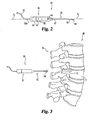
- Fig. 2 illustrates one embodiment of device 60.
- Device 60 extends generally along a longitudinal axis L and includes a handle member 61 and a probe member 62.
- Handle member 61 is composed of an insulative member or coating surrounding an inner portion 63.
- inner portion 63 carries a circuit 64 and a motor 65 which operates to rotate probe member 62 about longitudinal axis L.
- Inner portion 63 includes a rotatable coupling member 66 at a distal end thereof to operably connect with probe member 62.
- handle member 61 and probe member 62 can be operably, rotatably, and electrically coupled together by any suitable means, including threaded connections, ball-detent type connections, friction fits, slip fits, fasteners, and bayonet locks, for example.
- handle member 61 is operable to indicate to the operator that probe member 62 is coupled thereto. Such connection can switch on a display of the system, a light on the instrument, provide an audible indication, or provide any other suitable indicator.
- Probe member 62 can be provided in electrical engagement with an electrical current source to determine the proximity of neural elements relative to a location of probe member 62.
- an electrical lead can extend from probe member 62, through handle member 61, to nerve monitoring system 30.
- Probe member 62 includes a longitudinal section 67 at a proximal end and an angled section 68 adjacent a distal end of probe member 62.
- Angled section 68 includes a non-insulated probe end 69 at a distal end of probe member 62.
- Probe end 69 can be in the form of a ball tip or dissection or resection member that rotates about longitudinal axis L to sweep the hole formed in the bone tissue.
- the ball tip or other probe end is expandable to facilitate in tissue dilation and hole formation in bone tissue.
- a set of probe members is provided and attachable with a handle portion. The set of probe members can be provided with ends of various sizes for insertion into the bone tissue for sequential dilation of the hole in the tissue.
- angled section 68 is generally cylindrically shaped and probe end 69 is generally spherically shaped.
- handle member 61 and longitudinal section 67 of probe member 62 are generally cylindrically shaped about longitudinal axis L.
- Longitudinal section 67 and angled section 68 are composed of an electrically conductive material with an insulative member or coating thereabout to prevent shunting of electricity delivered therethrough to adjacent tissue or devices.
- Probe end 69 is not insulated so that the electrical signal carried thereby is exposed to the adjacent bone tissue.
- Fig. 3 illustrates the relationship of device 60 to a segment 70 of spinal column B.
- segment 70 includes a vertebra 71 which includes a hole 72 formed in a spinal pedicle.
- Probe member 62 is configured for insertion in or for forming hole 72 during normal use. After positioning in hole 72, probe end 69 rotates about longitudinal axis L to sweep hole 72 for defects. The proximity of neural elements to probe end 69 in the bone tissue surrounding hole 72 provides an indication of defects that expose neural elements.
- device 60 can also form a hole or bore in the bone tissue while locating defects therein.
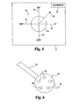
- Fig. 4 illustrates one embodiment of a display device 34 during operation of system 20.
- Display device 34 provides a diagram 80 according to one embodiment.
- Diagram 80 generally includes four vectors 82 representing positions of 0, 90, 180, and 270 degrees about longitudinal axis L relative to a particular orientation of handle member 61 relative to hole 72.
- Diagram 80 further includes a representation 84 of the sweeping rotational movement of probe end 69 in hole 72.
- Diagram 80 may also include an indication of a defect location in the bone tissue around hole 72 with a defect indicator 86.
- the location of defect indicator 86 relative to vectors 82 enables an operator of system 20 to determine the location of the defect about hole 72 in view of the relative orientation of handle member 61 with hole 72.
- defect indicator 86 has a blinking effect on operator display device 34 for increased visibility.
- operator display device 34 may display a representation 88 of the electrical current, voltage or the like supplied to probe end 69.
- a hole location for a hole in the bone tissue is identified, such as hole 72 for example.
- the bone tissue is an area of tissue within a spinal pedicle wall of vertebra 71 of spinal segment 70.
- probe end 69 of probe member 62 is inserted into hole 72.
- the probe end 69 can be manipulated to form an opening in the bone tissue along a particular path.
- probe end 69 is provided with an electrical signal so that the opening or hole can be swept for identification of defects.
- Probe end 69 is then rotated by motor 65 about longitudinal axis L. The continuous rotation of probe end 69 is illustrated on operator display device 34 as representation 84.
- An operator of system 20 can view display device 34 to monitor the rotation of probe end 69 in hole 72.
- the current at probe end 69 and patient reaction is monitored at stage 108 while probe end 69 continuously rotates about longitudinal axis L within hole 72 to determine the proximity of neural elements.
- the signal in probe end 69 will invoke a response by the patient that is recorded by system 30 to indicate that a neural element is in close proximity and a defect is present in the bone tissue about the hole.
- the location of probe end 69 relative to the opening in the bone tissue that results in the response is indicated by defect indicator 86.
- Procedure 100 continues at stage 110 where it is determined if the current at probe end 69 is below a predetermined threshold.
- the predetermined threshold can be the current at probe end 69 that invokes a response from the patient that indicates probe end 69 is sufficiently close in proximity with a neural element that hole 72 should be redirected to avoid the neural element. If the current flow is below the predetermined threshold and there is no indication of the presence of a defect or neural element at stage 112, the current is increased at stage 114 and the procedure is repeated at stage 110.
- stage 110 the procedure continues at stage 116 where is determined whether a defect or neural element has been indicated. If not, then the procedure continues at stage 118 where the hole is determined to be without an indicated defect, and hole preparation and/or anchor insertion continues. If a defect has been indicated at either of stage 112 or stage 116, a signal can be provided to circuit 64 that stops motor 65 from rotating probe end 69. Accordingly, probe end 69 stops rotating in alignment with the location about the hole in which the defect or neural element has been located, as indicated by the position of defect indicator 86 on operator display device 34. The operator of system 20 can view the relative location of indicator 86 and correlate it with a marker on device 60 to discern the relative location of the defect in hole 72. Another location and hole for insertion of a screw or anchor can be provided, or probe member 62 can be re-directed in a direction away from the location of the defect to re-route or re-direct the hole being formed.
- Probe member 162 which can be attachable to a handle portion, such as handle portion 61.
- Probe member 162 includes a probe end 164 illustrated in the form of a ball tip but may take any suitable form.
- Probe member 162 can include an elongated linear shaft portion that may or may not include a distal angled portion as discussed above.
- Probe end 164 includes a plurality of stimulation elements 166 spaced thereabout. Individual ones of the stimulation elements 166 can be alternately and sequentially energized to spatially deliver an electrical signal to the bone tissue about probe end 164.
- the neural stimulation delivered by individual ones of the stimulation elements 166 can be monitored and compared to one another and/or to a known threshold.
- the current flow or other condition of one or more of the stimulation elements 166 providing neural stimulation can indicate the presence of a defect in the bone wall or tissue that provides an electrical path to the neural element.
- the identification of the particular stimulation element indicating the presence defect can provide an indication of the location of the defect relative to the longitudinal axis of the probe member.
- the probe member need not be rotated in the hole in the bone tissue since electrical stimulation is provided and directed from various locations about the probe end.
- one or more stimulation elements create an external electrical field relative to the hole to be probed.
- the probe end is provided with sensors about its tip that alternately and sequentially measure neural stimulation created by the external stimulation about the hole.
- the sensor detecting neural stimulation from within the hole provides an indication of the presence and location of a defect in the bone tissue relative to the probe end inserted in the hole in the bone tissue.
Landscapes
- Health & Medical Sciences (AREA)
- Life Sciences & Earth Sciences (AREA)
- Surgery (AREA)
- Neurology (AREA)
- General Health & Medical Sciences (AREA)
- Public Health (AREA)
- Animal Behavior & Ethology (AREA)
- Engineering & Computer Science (AREA)
- Biomedical Technology (AREA)
- Heart & Thoracic Surgery (AREA)
- Medical Informatics (AREA)
- Molecular Biology (AREA)
- Veterinary Medicine (AREA)
- Orthopedic Medicine & Surgery (AREA)
- Pathology (AREA)
- Biophysics (AREA)
- Physics & Mathematics (AREA)
- Nuclear Medicine, Radiotherapy & Molecular Imaging (AREA)
- Neurosurgery (AREA)
- Radiology & Medical Imaging (AREA)
- Physiology (AREA)
- Dentistry (AREA)
- Oral & Maxillofacial Surgery (AREA)
- Rheumatology (AREA)
- Surgical Instruments (AREA)
- Ultra Sonic Daignosis Equipment (AREA)
Description
- Surgery for a patient can be painful and traumatic, particularly in the affected area of the patient's body. To accomplish spinal fixation, a necessary procedure often involves inserting spinal pedicle screws into a pedicle wall of a vertebra in a patient's spine. Pedicle screws are advantageous in that they are strong and provide stability, however, care must be taken to avoid nerve impingement during the placement of pedicle screws in the spine. Measures taken to locate any potential defects before insertion of a pedicle screw can facilitate screw insertion.
- Locating defects such as openings in bone tissue that expose nerves can be difficult. Some procedures involve monitoring muscle reactions to electrical stimulation to locate nerves in an area of bone tissue. If a nerve is not located and a screw contacts an exposed nerve, the screw can impinge on the nerve or become too close to the nerve root causing pain and other implications for the patient. Additionally, it is often too late to reverse the nerve damage that is caused by removing the screw or conducting other remedial procedures. In a procedure in which a screw is inserted into a pedicle wall without first determining the proximity of neural elements, it is very difficult to determine the existence and/or proximity of any defects in the bone tissue, what areas of the pedicle wall have been breached or contain a defect, and where to redirect the pedicle screw to avoid the breached wall or defect. There remains a need for instruments and methods that can be employed for locating any defects in bone tissue surrounding a hole in which a screw or other anchoring mechanism will be inserted. The present invention is directed to meeting these needs, among others.
-
WO03/037170 - The invention is defined in the appended claims.
- According to the invention, an instrument to indicate defects within bone tissue is provided with a handle member and a probe member. The handle member has a rotatable coupling member for connection with the probe member. The probe member extends distally from the handle member and includes a shaft portion and an angled portion. The angled portion extends transversely from the shaft portion and has a probe end. The probe end carries an electrical signal and the handle member operates to rotate the probe member and the probe end within a hole in bone tissue to locate neural elements in the bone tissue.
- Further, the invention involves a neural element and defect detection apparatus. The apparatus comprises a defect locating instrument with a handle member and a probe member. The probe member includes a longitudinal shaft portion and a distal angled portion. The distal angled portion includes a non-insulated probe end on its distal end that carries an electrical signal. The handle member rotates the probe member and the probe end about a longitudinal axis, while the probe end carries the electrical signal, to determine the proximity of neural elements and locate defects in bone tissue surrounding a hole. The apparatus further includes an operator display device to display a representation of the rotation of the probe end relative to the longitudinal axis and a representation of neural elements and defects in the bone tissue located by the probe end.
- Further, the invention involves a system comprising a handle member, a probe member, and a nerve monitoring system. The handle member includes a circuit and a motor which rotates a coupling member within the handle member. The probe member has a proximal end and a distal end opposite the proximal end. The proximal end of the probe member is removably coupled to the coupling member of the handle member. Additionally, the probe member has a longitudinal shaft portion along a longitudinal axis at its proximal end and a distal angled portion extending transversely to the longitudinal axis adjacent its distal end. The distal angled portion includes a probe end at its distal end which carries an electrical signal and is designed to rotate about the longitudinal axis to locate neural elements and defects in an area of bone tissue surrounding a hole. The nerve monitoring system is electrically coupled to the probe member.
-
-
Fig. 1 is a schematic view of a defect locating system. -
Fig. 2 is a partial, schematic view of a defect locating device. -
Fig. 3 is a partial, schematic view of a defect locating device relative to a section of a spine. -
Fig. 4 is a schematic view of a display. -
Fig. 5 is a flowchart of one type of diagnostic procedure that can be implemented with the system ofFig. 1 . -
Fig. 6 is another embodiment probe member usable with a defect locating system. - For the purposes of promoting an understanding of the principles of the invention, reference will now be made to the embodiments illustrated in the drawings and specific language will be used to describe the same. It will nevertheless be understood that no limitation of the scope of the invention is hereby intended, such alterations and further modifications in the illustrated devices, and such further applications of the principles of the invention as illustrated herein being contemplated as would normally occur to one skilled hi the art to which tine invention relates.
- An instrument for locating defects within bone tissue includes a handle member and a probe member. The handle member includes a rotatable coupling member connected with the probe member. The probe member extends distally from the handle member and includes a longitudinal shaft and an angled end. The angled end has a non-insulated probe end, such as a ball tip, on its distal end that is designed to rotate around a longitudinal axis. The probe end carries an electrical signal to determine the proximity of neural elements and rotates within a hole in bone tissue to locate defects hi the bone tissue. The detection of the occurrence and location of bone tissue defects in the hole directs the surgeon in forming the hole to receive a bone screw in a manner that avoids neural elements hi the bone tissue.
-
Fig. 1 illustrates asystem 20 that includes an instrument, which is a defect locatingdevice 60, and associated equipment arranged to provide medical treatment.System 20 is arranged to determine the proximity of neural elements and find defects within bone tissue surrounding a first hole in a pedicle wall of one or more vertebrae of spinal column B. - Based on the location of the defects found,
system 20 is arranged to allow for redirection of a defect locating device to find an area of bone tissue without defects and thus a more suitable location for forming a hole in and placement of a screw in a pedicle or other bony structure.System 20 includes nerve monitoring system 30, connection link 50, and defect locatingdevice 60. Nerve monitoring system 30 includesequipment 31 coupled todevice 60 with connection link 50, orequipment 31 can be integrated withdevice 60.Device 60 is configured for placement within a hole in a spinal pedicle wall of spinal column B of a human patient or subject, as schematically represented inFig. 1 . - In one embodiment, system 30 is part of the NIM-Spine™ System marketed by Medtronic, Inc. Another example of a probe and nerve monitoring procedure is provided in
U.S. Patent No. 5,474,558 to Neubardt . -
Equipment 31 may includeoperator input devices 32,operator display device 34, and various other operator-utilized equipment ofsystem 20 that is external to a patient during use.Input devices 32 may include an alphanumeric keyboard and mouse or other pointing device of a standard variety. Alternatively or additionally, one or more other input devices can be utilized, such as a voice input subsystem or a different type as would occur to those skilled in the art.Operator display device 34 can be of a Cathode Ray Tube (CRT) type, Liquid Crystal Display (LCD) type, plasma type, Organic Light Emitting Diode (OLED) type, or such different type as would occur to those skilled in the art. Alternatively or additionally, one or more other operator output devices can be utilized, such as a printer, one or more loudspeakers, headphones, or such different type as would occur to those skilled in the art. Nerve monitoring system 30 also can include one or more communication interfaces suitable for connection to a computer network, such as a Local Area Network (LAN), Municipal Area Network (MAN), and/or Wide Area Network (WAN) like the Internet; a medical diagnostic device; another therapeutic device; a medical imaging device; a Personal Digital Assistant (PDA) device; a digital still image or video camera; and/or audio device, to name only a few. Nerve monitoring system 30 can be arranged to show other information under control of the operator. -
Equipment 31 may also include processing subsystem 40 for processing signals and data associated withsystem 20. Subsystem 40 may includeanalog interface circuitry 42, Digital Signal Processor (DSP) 44,data processor 46, andmemory 48.Analog interface circuitry 42 can be responsive to control signals fromDSP 44 to provide corresponding analog stimulus signals todevice 60. At least one ofanalog interface circuitry 42 andDSP 44 may include one or more digital-to-analog converters (DAC) and one or more analog-to-digital converters (ADC) to facilitate operation ofsystem 20 in the manner to be described in greater detail hereinafter.Processor 46 can be coupled toDSP 44 to bidirectionally communicate therewith, selectively provide output to displaydevice 34, and selectively respond to input fromoperator input devices 32. -
DSP 44 and/orprocessor 46 can be of a programmable type; a dedicated, hardwired state machine; or a combination of these.DSP 44 andprocessor 46 perform in accordance with operating logic that can be defined by software programming instructions, firmware, dedicated hardware, a combination of these, or in a different manner as would occur to those skilled in the art. For a programmable form ofDSP 44 orprocessor 46, at least a portion of this operating logic can be defined by instructions stored inmemory 48. Programming ofDSP 44 and/orprocessor 46 can be of a standard, static type; an adaptive type provided by neural networking, expert-assisted learning, fuzzy logic, or the like; or a combination of these. -
Memory 48 is illustrated in association withprocessor 46; however,memory 48 can be separate from or at least partially included in one or more ofDSP 44 andprocessor 46.Memory 48 includes at least one Removable Memory Device (RMD) 48a.Memory 48 can be of a solid-state variety, electromagnetic variety, optical variety, or a combination of these forms. Furthermore,memory 48 can be volatile, nonvolatile, or a mixture of these types.Memory 48 can be at least partially integrated withcircuitry 42,DSP 44, and/orprocessor 46. RMD 48a can be a floppy disc, cartridge, or tape form of removable electromagnetic recording media; an optical disc, such as a CD or DVD type; an electrically reprogrammable solid-state type of nonvolatile memory, and/or such different variety as would occur to those skilled in the art. In still other embodiments, RMD 48a is absent. -
Circuitry 42,DSP 44, andprocessor 46 can be comprised of one or more components of any type suitable to operate as described herein. Further, it should be appreciated that all or any portion ofcircuitry 42,DSP 44, andprocessor 46 can be integrated together in a common device, and/or provided as multiple processing units. For a multiple processing unit form ofDSP 44 orprocessor 46; distributed, pipelined, and/or parallel processing can be utilized as appropriate. In one embodiment,circuitry 42 is provided as one or more components coupled to a dedicated integrated circuit form ofDSP 44;processor 46 is provided in the form of one or more general purpose central processing units that interface withDSP 44 over a standard bus connection; andmemory 48 includes dedicated memory circuitry integrated withinDSP 44 andprocessor 46, and one or more external memory components including a removable disk form of RMD 48a.Circuitry 42,DSP 44, and/orprocessor 46 can include one or more signal filters, limiters, oscillators, format converters (such as DACs or ADCs), power supplies, or other signal operators or conditioners as appropriate to operatesystem 20 in the manner to be described in greater detail hereinafter. - In one embodiment, connection link 50 includes flexible
electric cabling 52 withproximal end 52a oppositedistal end 52b, andconnector 54 electrically connected toequipment 31 of nerve monitoring system 30.Cabling 52 extends fromconnector 54 atproximal end 52a todistal end 52b where it is connected withdevice 60. Connection link 50 may include forms in addition to or in alternative to cabling 52, including one or more wires, cords, wireless links, infrared components, bluetooth, or other communication link. Further, it should be appreciated that other components, devices, and systems can be integrated intosystem 20, such as an endoscope system, a catheterization system, an imaging system, a lighting system, and/or a video camera system, to name a few examples. Connection link 50 anddevice 60 are movable toward and away from spinal column B in a surgical procedure that may include one or more of retractors, tubes, sleeves, guards, micro-incisions or other components not shown to enhance clarity. -
Fig. 2 illustrates one embodiment ofdevice 60.Device 60 extends generally along a longitudinal axis L and includes ahandle member 61 and aprobe member 62.Handle member 61 is composed of an insulative member or coating surrounding aninner portion 63. In one embodiment,inner portion 63 carries acircuit 64 and amotor 65 which operates to rotateprobe member 62 about longitudinal axisL. Inner portion 63 includes arotatable coupling member 66 at a distal end thereof to operably connect withprobe member 62. It should be appreciated that handlemember 61 andprobe member 62 can be operably, rotatably, and electrically coupled together by any suitable means, including threaded connections, ball-detent type connections, friction fits, slip fits, fasteners, and bayonet locks, for example. - In one embodiment, handle
member 61 is operable to indicate to the operator that probemember 62 is coupled thereto. Such connection can switch on a display of the system, a light on the instrument, provide an audible indication, or provide any other suitable indicator.Probe member 62 can be provided in electrical engagement with an electrical current source to determine the proximity of neural elements relative to a location ofprobe member 62. For example, an electrical lead can extend fromprobe member 62, throughhandle member 61, to nerve monitoring system 30. -
Probe member 62 includes alongitudinal section 67 at a proximal end and anangled section 68 adjacent a distal end ofprobe member 62.Angled section 68 includes anon-insulated probe end 69 at a distal end ofprobe member 62. Probeend 69 can be in the form of a ball tip or dissection or resection member that rotates about longitudinal axis L to sweep the hole formed in the bone tissue. In one embodiment, the ball tip or other probe end is expandable to facilitate in tissue dilation and hole formation in bone tissue. In another embodiment, a set of probe members is provided and attachable with a handle portion. The set of probe members can be provided with ends of various sizes for insertion into the bone tissue for sequential dilation of the hole in the tissue. - In the illustrated embodiment, angled
section 68 is generally cylindrically shaped and probeend 69 is generally spherically shaped. Additionally, handlemember 61 andlongitudinal section 67 ofprobe member 62 are generally cylindrically shaped about longitudinal axisL. Longitudinal section 67 andangled section 68 are composed of an electrically conductive material with an insulative member or coating thereabout to prevent shunting of electricity delivered therethrough to adjacent tissue or devices. Probeend 69 is not insulated so that the electrical signal carried thereby is exposed to the adjacent bone tissue. -
Fig. 3 illustrates the relationship ofdevice 60 to asegment 70 of spinal column B. In the illustrated embodiment,segment 70 includes avertebra 71 which includes ahole 72 formed in a spinal pedicle.Probe member 62 is configured for insertion in or for forminghole 72 during normal use. After positioning inhole 72,probe end 69 rotates about longitudinal axis L to sweephole 72 for defects. The proximity of neural elements to probeend 69 in the bonetissue surrounding hole 72 provides an indication of defects that expose neural elements. In an alternative embodiment and alternative operation ofsystem 20,device 60 can also form a hole or bore in the bone tissue while locating defects therein. -
Fig. 4 illustrates one embodiment of adisplay device 34 during operation ofsystem 20.Display device 34 provides a diagram 80 according to one embodiment. Diagram 80 generally includes fourvectors 82 representing positions of 0, 90, 180, and 270 degrees about longitudinal axis L relative to a particular orientation ofhandle member 61 relative to hole 72. Diagram 80 further includes arepresentation 84 of the sweeping rotational movement ofprobe end 69 inhole 72. Diagram 80 may also include an indication of a defect location in the bone tissue aroundhole 72 with adefect indicator 86. The location ofdefect indicator 86 relative tovectors 82 enables an operator ofsystem 20 to determine the location of the defect abouthole 72 in view of the relative orientation ofhandle member 61 withhole 72. In one embodiment,defect indicator 86 has a blinking effect onoperator display device 34 for increased visibility. Additionally,operator display device 34 may display a representation 88 of the electrical current, voltage or the like supplied to probeend 69. - An example of a
procedure 100 for operatingsystem 20 is provided inFig. 5 . Atstage 102, a hole location for a hole in the bone tissue is identified, such ashole 72 for example. In one embodiment, the bone tissue is an area of tissue within a spinal pedicle wall ofvertebra 71 ofspinal segment 70. Atstage 104, probe end 69 ofprobe member 62 is inserted intohole 72. Theprobe end 69 can be manipulated to form an opening in the bone tissue along a particular path. Atstage 106,probe end 69 is provided with an electrical signal so that the opening or hole can be swept for identification of defects. Probeend 69 is then rotated bymotor 65 about longitudinal axis L. The continuous rotation ofprobe end 69 is illustrated onoperator display device 34 asrepresentation 84. An operator ofsystem 20 can viewdisplay device 34 to monitor the rotation ofprobe end 69 inhole 72. The current atprobe end 69 and patient reaction is monitored atstage 108 while probe end 69 continuously rotates about longitudinal axis L withinhole 72 to determine the proximity of neural elements. The signal inprobe end 69 will invoke a response by the patient that is recorded by system 30 to indicate that a neural element is in close proximity and a defect is present in the bone tissue about the hole. The location ofprobe end 69 relative to the opening in the bone tissue that results in the response is indicated bydefect indicator 86. -
Procedure 100 continues atstage 110 where it is determined if the current atprobe end 69 is below a predetermined threshold. The predetermined threshold can be the current atprobe end 69 that invokes a response from the patient that indicatesprobe end 69 is sufficiently close in proximity with a neural element thathole 72 should be redirected to avoid the neural element. If the current flow is below the predetermined threshold and there is no indication of the presence of a defect or neural element atstage 112, the current is increased atstage 114 and the procedure is repeated atstage 110. - If at
stage 110 the current is determined to not be below the threshold, then the procedure continues atstage 116 where is determined whether a defect or neural element has been indicated. If not, then the procedure continues atstage 118 where the hole is determined to be without an indicated defect, and hole preparation and/or anchor insertion continues. If a defect has been indicated at either ofstage 112 orstage 116, a signal can be provided tocircuit 64 that stopsmotor 65 from rotatingprobe end 69. Accordingly, probeend 69 stops rotating in alignment with the location about the hole in which the defect or neural element has been located, as indicated by the position ofdefect indicator 86 onoperator display device 34. The operator ofsystem 20 can view the relative location ofindicator 86 and correlate it with a marker ondevice 60 to discern the relative location of the defect inhole 72. Another location and hole for insertion of a screw or anchor can be provided, orprobe member 62 can be re-directed in a direction away from the location of the defect to re-route or re-direct the hole being formed. - In
Fig. 6 there is shown anotherembodiment probe member 162 which can be attachable to a handle portion, such ashandle portion 61.Probe member 162 includes aprobe end 164 illustrated in the form of a ball tip but may take any suitable form.Probe member 162 can include an elongated linear shaft portion that may or may not include a distal angled portion as discussed above. Probeend 164 includes a plurality ofstimulation elements 166 spaced thereabout. Individual ones of thestimulation elements 166 can be alternately and sequentially energized to spatially deliver an electrical signal to the bone tissue aboutprobe end 164. - The neural stimulation delivered by individual ones of the
stimulation elements 166 can be monitored and compared to one another and/or to a known threshold. The current flow or other condition of one or more of thestimulation elements 166 providing neural stimulation can indicate the presence of a defect in the bone wall or tissue that provides an electrical path to the neural element. The identification of the particular stimulation element indicating the presence defect can provide an indication of the location of the defect relative to the longitudinal axis of the probe member. The probe member need not be rotated in the hole in the bone tissue since electrical stimulation is provided and directed from various locations about the probe end. - In another embodiment, one or more stimulation elements create an external electrical field relative to the hole to be probed. The probe end is provided with sensors about its tip that alternately and sequentially measure neural stimulation created by the external stimulation about the hole. The sensor detecting neural stimulation from within the hole provides an indication of the presence and location of a defect in the bone tissue relative to the probe end inserted in the hole in the bone tissue.
- While the invention has been illustrated and described in detail in the drawings and foregoing description, the same is to be considered as illustrative and not restrictive in character.
Claims (22)
- An instrument (60) for locating defects within bone tissue, comprising:a handle member (61) including a rotatable coupling member (66); anda probe member (62) coupled to said coupling member of said handle member and extending distally therefrom, wherein said probe member includes a longitudinal shaft portion (67) along a longitudinal axis (L) and characterised in that said probe member includes a distal angled portion (68) extending transversely to said longitudinal axis, wherein said angled portion includes a probe end (69) at a distal end thereof for carrying an electrical signal, wherein said handle member is operable to rotate said coupling member and said probe member and said probe end about said longitudinal axis to locate defects in bone tissue during sweeping rotational movement of the probe end.
- The instrument of claim 1, wherein said probe end is a ball tip.
- The instrument of claim 1, wherein said handle member extends along said longitudinal axis.
- The instrument of claim 1, further comprising an electrical lead extending from said probe member through said handle member.
- The instrument of claim 1, wherein said longitudinal shaft portion and said distal angled portion are composed of an electrically conductive material and are insulated.
- The instrument of claim 5, wherein said probe end is non-insulated.
- The instrument of claim 1, wherein at least said distal angled portion of said probe member is structured for positioning in a hole formed in a spinal pedicle wall to receive an anchor.
- The instrument of claim 1, wherein said handle member includes a motor operable to rotate said coupling member and said probe member about said longitudinal axis.
- The instrument of claim 1, wherein said handle member includes a circuit and a motor operable to rotate said probe member about the longitudinal axis within a first hole in the bone tissue.
- The instrument of claim 9, wherein said handle member is operable to automatically stop rotation of said probe member at the defect location in the bone tissue.
- The instrument of claim 1, wherein in operation:said probe end is operable to stop rotation in alignment with a defect in the bone tissue.
- The instrument of claim 1, further comprising a connection link extending from a proximal end of said handle member to a nerve monitoring system.
- The instrument of claim 1, wherein said probe member is operable for rotation about said longitudinal axis when said probe end is positioned in a first hole in the bone tissue.
- The instrument of claim 13, wherein the instrument is operable to automatically stop rotation of said probe member upon detection of the defect.
- A neural element detection apparatus, comprising:the instrument (60) of claim 1, wherein said probe end (69) is operable to rotate about the longitudinal axis to detect neural elements in bone tissue about a first hole in a pedicle wall when inserted in the hole; andan operator display device (34) to display a representation of the rotation of said probe end relative to the longitudinal axis and a location of a defect indicated by detection of neural elements in the bone tissue about said probe end.
- The apparatus of claim 15, wherein:upon detection of the neural element a signal is provided to said locating instrument to stop rotation of said probe end adjacent the defect; andsaid operator display device is operable to display a location of the probe end and thus the defect relative to the longitudinal axis.
- The apparatus of claim 15, wherein:said shaft portion and said angled portion are insulated and are composed of an electrically conductive material; andsaid probe end is non-insulated.
- The apparatus of claim 15, further comprising a nerve monitoring system electrically coupled to said locating instrument.
- A system, comprising:the instrument (60) of claim 1, wherein said handle member includes a circuit and a motor operable to rotate said coupling member of said handle member and whereinsaid probe member (62) includes a proximal end and a distal end opposite said proximal end, wherein said proximal end of said probe member is coupled to said coupling member of said handle member, wherein said longitudinal shaft portion extends along a longitudinal axis at said proximal end and said distal angled portion extends transversely to said longitudinal axis adjacent said distal end, wherein said probe end (69) is operable to detect neural elements in bone tissue; anda nerve monitoring system electrically coupled to said probe member operable to indicate a proximity of neural elements to said probe end.
- The system of claim 19, wherein said nerve monitoring system includes an operator display device operable to display a location of said probe end relative to said longitudinal axis.
- The system of claim 20, wherein upon detection of a neural element a defect in the bone tissue is located and the system is operable to provide a signal to said circuit to stop said motor and rotation of said probe member with said probe end adjacent the defect.
- The system of claim 21, wherein said operator display device is operable to display a location of the defect relative to said longitudinal axis.
Applications Claiming Priority (2)
| Application Number | Priority Date | Filing Date | Title |
|---|---|---|---|
| US11/052,666 US20060178594A1 (en) | 2005-02-07 | 2005-02-07 | Apparatus and method for locating defects in bone tissue |
| PCT/US2006/004237 WO2006086363A2 (en) | 2005-02-07 | 2006-02-06 | Apparatus and method for locating defects in bone tissue |
Publications (2)
| Publication Number | Publication Date |
|---|---|
| EP1848331A2 EP1848331A2 (en) | 2007-10-31 |
| EP1848331B1 true EP1848331B1 (en) | 2015-04-08 |
Family
ID=36572392
Family Applications (1)
| Application Number | Title | Priority Date | Filing Date |
|---|---|---|---|
| EP06734485.3A Active EP1848331B1 (en) | 2005-02-07 | 2006-02-06 | Apparatus for locating defects in bone tissue |
Country Status (7)
| Country | Link |
|---|---|
| US (2) | US20060178594A1 (en) |
| EP (1) | EP1848331B1 (en) |
| JP (1) | JP4959585B2 (en) |
| KR (1) | KR20070110322A (en) |
| CN (1) | CN101150982A (en) |
| AU (1) | AU2006212868B2 (en) |
| WO (1) | WO2006086363A2 (en) |
Families Citing this family (30)
| Publication number | Priority date | Publication date | Assignee | Title |
|---|---|---|---|---|
| US20040225228A1 (en) * | 2003-05-08 | 2004-11-11 | Ferree Bret A. | Neurophysiological apparatus and procedures |
| DE202005000544U1 (en) * | 2005-01-13 | 2006-05-24 | Mantsch, Christian | Medical electrode system |
| US8092455B2 (en) | 2005-02-07 | 2012-01-10 | Warsaw Orthopedic, Inc. | Device and method for operating a tool relative to bone tissue and detecting neural elements |
| US20070276286A1 (en) * | 2006-05-27 | 2007-11-29 | Craig James Miller | Device for Tissue Diagnosis and Spatial Tissue Mapping |
| US8374673B2 (en) | 2007-01-25 | 2013-02-12 | Warsaw Orthopedic, Inc. | Integrated surgical navigational and neuromonitoring system having automated surgical assistance and control |
| US7987001B2 (en) | 2007-01-25 | 2011-07-26 | Warsaw Orthopedic, Inc. | Surgical navigational and neuromonitoring instrument |
| US8326414B2 (en) * | 2007-04-20 | 2012-12-04 | Warsaw Orthopedic, Inc. | Nerve stimulating drill bit |
| US8075601B2 (en) * | 2007-04-30 | 2011-12-13 | Warsaw Orthopedic, Inc. | Deformity correction using neural integrity monitoring |
| US8348983B2 (en) * | 2007-11-13 | 2013-01-08 | Warsaw Orthopedic, Inc. | Surgical bone screw construction |
| US8019443B2 (en) | 2008-04-01 | 2011-09-13 | Boston Scientific Neuromodulation Corporation | Anchoring units for leads of implantable electric stimulation systems and methods of making and using |
| US9320891B2 (en) | 2008-04-02 | 2016-04-26 | Boston Scientific Neuromodulation Corporation | Lead anchor for implantable devices and methods of manufacture and use |
| US9887470B2 (en) | 2009-04-27 | 2018-02-06 | Boston Scienific Neuromodulation Corporation | Torque lock anchor and methods and devices using the anchor |
| US9352147B2 (en) | 2009-04-27 | 2016-05-31 | Boston Scientific Neuromodulation Corporation | Torque lock anchor and methods and devices using the anchor |
| US8206306B2 (en) * | 2009-05-07 | 2012-06-26 | Hitachi Aloka Medical, Ltd. | Ultrasound systems and methods for orthopedic applications |
| CN102421374B (en) * | 2009-05-07 | 2014-12-17 | 日立阿洛卡医疗株式会社 | Ultrasound systems for orthopedic applications |
| US20110230785A1 (en) * | 2010-03-16 | 2011-09-22 | ProNerve, LLC | Somatosensory Evoked Potential (SSEP) Automated Alert System |
| US10117564B2 (en) | 2010-04-16 | 2018-11-06 | Hitachi Healthcare Americas Corporation | Ultrasound and detachable instrument for procedures |
| US9629646B2 (en) | 2012-07-11 | 2017-04-25 | Jens Kather | Curved burr surgical instrument |
| US9216563B2 (en) | 2013-08-19 | 2015-12-22 | Boston Scientific Neuromodulation Corporation | Lead anchor with adhesive and systems and methods using the lead anchor |
| US9517334B2 (en) | 2013-08-19 | 2016-12-13 | Boston Scientific Neuromodulation Corporation | Lead anchors and systems and methods employing the lead anchors |
| US9415212B2 (en) | 2014-02-28 | 2016-08-16 | Boston Scientific Neuromodulation Corporation | Side loading lead anchor and methods of making and using thereof |
| US9987482B2 (en) | 2014-05-27 | 2018-06-05 | Boston Scientific Neuromodulation Corporation | Systems and methods for making and using reversible mechanical lead anchors for electrical stimulation systems |
| CN105030334A (en) * | 2015-06-10 | 2015-11-11 | 中国人民解放军第二军医大学 | Opening navigation detection system for spinal surgeries |
| US9636498B2 (en) | 2015-08-03 | 2017-05-02 | Boston Scientific Neuromodulation Corporation | Lead anchor with a wedge and systems using the lead anchor |
| WO2017151438A1 (en) | 2016-02-29 | 2017-09-08 | Boston Scientific Neuromodulation Corporation | Lead anchor for an electrical stimulation system |
| US10369354B2 (en) | 2016-05-17 | 2019-08-06 | Boston Scientific Neuromodulation Corporation | Systems and method for anchoring a lead for neurostimulation of a target anatomy |
| EP3518759A1 (en) * | 2016-09-30 | 2019-08-07 | Universidade do Porto | Injectable hydrogel-forming polymer solution for a reliable eeg monitoring and easy scalp cleaning |
| US10709886B2 (en) | 2017-02-28 | 2020-07-14 | Boston Scientific Neuromodulation Corporation | Electrical stimulation leads and systems with elongate anchoring elements and methods of making and using |
| US10835739B2 (en) | 2017-03-24 | 2020-11-17 | Boston Scientific Neuromodulation Corporation | Electrical stimulation leads and systems with elongate anchoring elements and methods of making and using |
| US10857351B2 (en) | 2017-04-28 | 2020-12-08 | Boston Scientific Neuromodulation Corporation | Lead anchors for electrical stimulation leads and systems and methods of making and using |
Family Cites Families (104)
| Publication number | Priority date | Publication date | Assignee | Title |
|---|---|---|---|---|
| US1926865A (en) * | 1932-04-16 | 1933-09-12 | Gen Railway Signal Co | Rubber insulated coil and method of making the same |
| US2704064A (en) * | 1952-09-10 | 1955-03-15 | Meditron Company | Neurosurgical stimulator |
| US3364929A (en) * | 1964-12-21 | 1968-01-23 | Burroughs Wellcome Co | Method for administering muscle relaxant drug |
| US3682162A (en) * | 1968-12-13 | 1972-08-08 | Wellcome Found | Combined electrode and hypodermic syringe needle |
| US3664329A (en) * | 1970-03-09 | 1972-05-23 | Concept | Nerve locator/stimulator |
| US3811449A (en) * | 1972-03-08 | 1974-05-21 | Becton Dickinson Co | Dilating apparatus and method |
| US3830226A (en) * | 1973-06-15 | 1974-08-20 | Concept | Variable output nerve locator |
| US3892232A (en) * | 1973-09-24 | 1975-07-01 | Alonzo J Neufeld | Method and apparatus for performing percutaneous bone surgery |
| US3957036A (en) * | 1975-02-03 | 1976-05-18 | Baylor College Of Medicine | Method and apparatus for recording activity in intact nerves |
| GB1534162A (en) * | 1976-07-21 | 1978-11-29 | Lloyd J | Cyosurgical probe |
| US4099519A (en) * | 1977-01-14 | 1978-07-11 | Warren Fred E | Diagnostic device |
| US4224949A (en) * | 1977-11-17 | 1980-09-30 | Cornell Research Foundation, Inc. | Method and electrical resistance probe for detection of estrus in bovine |
| US4235242A (en) * | 1979-04-02 | 1980-11-25 | Med General, Inc. | Electronic circuit permitting simultaneous use of stimulating and monitoring equipment |
| US4285347A (en) * | 1979-07-25 | 1981-08-25 | Cordis Corporation | Stabilized directional neural electrode lead |
| USRE34390E (en) * | 1980-12-31 | 1993-09-28 | Nicolet Instrument Corporation | Apparatus and method for topographic display of multichannel EEG data |
| US4592369A (en) * | 1982-07-12 | 1986-06-03 | National Research Development Corp. | Method and apparatus for use in temporal analysis of waveforms |
| US4545374A (en) * | 1982-09-03 | 1985-10-08 | Jacobson Robert E | Method and instruments for performing a percutaneous lumbar diskectomy |
| US4519403A (en) * | 1983-04-29 | 1985-05-28 | Medtronic, Inc. | Balloon lead and inflator |
| US4515168A (en) * | 1983-07-22 | 1985-05-07 | Chester Martin H | Clamp-on nerve stimulator and locator |
| US4573448A (en) * | 1983-10-05 | 1986-03-04 | Pilling Co. | Method for decompressing herniated intervertebral discs |
| US4616660A (en) * | 1984-12-10 | 1986-10-14 | Suncoast Medical Manufacturing, Inc. | Variable alternating current output nerve locator/stimulator |
| US4633889A (en) * | 1984-12-12 | 1987-01-06 | Andrew Talalla | Stimulation of cauda-equina spinal nerves |
| US4658835A (en) * | 1985-07-25 | 1987-04-21 | Cordis Corporation | Neural stimulating lead with fixation canopy formation |
| EP0233258A1 (en) * | 1985-08-16 | 1987-08-26 | BROWN, David | Electromyographic repetitive strain injury monitor |
| US4892105A (en) * | 1986-03-28 | 1990-01-09 | The Cleveland Clinic Foundation | Electrical stimulus probe |
| US4759377A (en) * | 1986-11-26 | 1988-07-26 | Regents Of The University Of Minnesota | Apparatus and method for mechanical stimulation of nerves |
| US4823791A (en) * | 1987-05-08 | 1989-04-25 | Circon Acmi Division Of Circon Corporation | Electrosurgical probe apparatus |
| DE8803153U1 (en) * | 1988-03-09 | 1988-06-23 | B. Braun Melsungen Ag, 3508 Melsungen | Catheter device for plexus anesthesia |
| US5127403A (en) * | 1988-07-05 | 1992-07-07 | Cardiac Control Systems, Inc. | Pacemaker catheter utilizing bipolar electrodes spaced in accordance to the length of a heart depolarization signal |
| US5058602A (en) * | 1988-09-30 | 1991-10-22 | Brody Stanley R | Paraspinal electromyography scanning |
| US4964411A (en) * | 1989-07-13 | 1990-10-23 | Empi, Inc. | Evoked EMG signal processing |
| US4962766A (en) * | 1989-07-19 | 1990-10-16 | Herzon Garrett D | Nerve locator and stimulator |
| US5454365A (en) * | 1990-11-05 | 1995-10-03 | Bonutti; Peter M. | Mechanically expandable arthroscopic retractors |
| US5095905A (en) * | 1990-06-07 | 1992-03-17 | Medtronic, Inc. | Implantable neural electrode |
| US5092344A (en) * | 1990-11-19 | 1992-03-03 | Lee Tzium Shou | Remote indicator for stimulator |
| SE467561B (en) * | 1990-12-04 | 1992-08-10 | Dorsograf Ab | DEVICE FOR SEATING TRANSPORT TIME OF NERV SIGNALS |
| US5091990A (en) * | 1991-02-15 | 1992-02-25 | Augat Communications Group | Fiber-optic connector |
| US5480440A (en) * | 1991-08-15 | 1996-01-02 | Smith & Nephew Richards, Inc. | Open surgical technique for vertebral fixation with subcutaneous fixators positioned between the skin and the lumbar fascia of a patient |
| US5242443A (en) * | 1991-08-15 | 1993-09-07 | Smith & Nephew Dyonics, Inc. | Percutaneous fixation of vertebrae |
| US5161533A (en) * | 1991-09-19 | 1992-11-10 | Xomed-Treace Inc. | Break-apart needle electrode system for monitoring facial EMG |
| US5255691A (en) * | 1991-11-13 | 1993-10-26 | Medtronic, Inc. | Percutaneous epidural lead introducing system and method |
| US5284153A (en) * | 1992-04-14 | 1994-02-08 | Brigham And Women's Hospital | Method for locating a nerve and for protecting nerves from injury during surgery |
| US5474558A (en) * | 1992-04-30 | 1995-12-12 | Neubardt; Seth L. | Procedure and system for spinal pedicle screw insertion |
| US5196015A (en) * | 1992-04-30 | 1993-03-23 | Neubardt Seth L | Procedure for spinal pedicle screw insertion |
| US5306275A (en) * | 1992-12-31 | 1994-04-26 | Bryan Donald W | Lumbar spine fixation apparatus and method |
| US5566678B1 (en) * | 1993-09-10 | 1999-11-30 | Cadwell Ind Inc | Digital eeg noise synthesizer |
| US5433739A (en) * | 1993-11-02 | 1995-07-18 | Sluijter; Menno E. | Method and apparatus for heating an intervertebral disc for relief of back pain |
| US5599345A (en) * | 1993-11-08 | 1997-02-04 | Zomed International, Inc. | RF treatment apparatus |
| US5560372A (en) * | 1994-02-02 | 1996-10-01 | Cory; Philip C. | Non-invasive, peripheral nerve mapping device and method of use |
| DE19520765B4 (en) * | 1994-06-09 | 2004-07-08 | Kabushiki Kaisha Morita Seisakusho | Dental treatment facility with root canal length measurement function |
| US5593429A (en) * | 1994-06-28 | 1997-01-14 | Cadwell Industries, Inc. | Needle electrode with depth of penetration limiter |
| US5482038A (en) * | 1994-06-28 | 1996-01-09 | Cadwell Industries, Inc. | Needle electrode assembly |
| US5540235A (en) * | 1994-06-30 | 1996-07-30 | Wilson; John R. | Adaptor for neurophysiological monitoring with a personal computer |
| US5630813A (en) * | 1994-12-08 | 1997-05-20 | Kieturakis; Maciej J. | Electro-cauterizing dissector and method for facilitating breast implant procedure |
| US5671752A (en) * | 1995-03-31 | 1997-09-30 | Universite De Montreal/The Royal Insitution For The Advancement Of Learning (Mcgill University) | Diaphragm electromyography analysis method and system |
| CA2229391C (en) * | 1995-04-10 | 2005-09-27 | Admir Hadzic | Peripheral nerve stimulation device for unassisted nerve blockade |
| US5711307A (en) * | 1995-04-13 | 1998-01-27 | Liberty Mutual Insurance Company | Method and apparatus for detecting myoelectric activity from the surface of the skin |
| US5775331A (en) * | 1995-06-07 | 1998-07-07 | Uromed Corporation | Apparatus and method for locating a nerve |
| US5807275A (en) * | 1995-07-19 | 1998-09-15 | Medical Biopsy, Inc. | Biopsy needle |
| US5797854A (en) * | 1995-08-01 | 1998-08-25 | Hedgecock; James L. | Method and apparatus for testing and measuring current perception threshold and motor nerve junction performance |
| US6283960B1 (en) * | 1995-10-24 | 2001-09-04 | Oratec Interventions, Inc. | Apparatus for delivery of energy to a surgical site |
| US5779642A (en) * | 1996-01-16 | 1998-07-14 | Nightengale; Christopher | Interrogation device and method |
| US5928158A (en) * | 1997-03-25 | 1999-07-27 | Aristides; Arellano | Medical instrument with nerve sensor |
| US6050992A (en) * | 1997-05-19 | 2000-04-18 | Radiotherapeutics Corporation | Apparatus and method for treating tissue with multiple electrodes |
| US6146335A (en) * | 1997-07-01 | 2000-11-14 | Neurometrix, Inc. | Apparatus for methods for the assessment of neuromuscular function of the lower extremity |
| US6132387A (en) * | 1997-07-01 | 2000-10-17 | Neurometrix, Inc. | Neuromuscular electrode |
| US5851191A (en) * | 1997-07-01 | 1998-12-22 | Neurometrix, Inc. | Apparatus and methods for assessment of neuromuscular function |
| US6132386A (en) * | 1997-07-01 | 2000-10-17 | Neurometrix, Inc. | Methods for the assessment of neuromuscular function by F-wave latency |
| US5876405A (en) * | 1997-09-17 | 1999-03-02 | The Anspach Effort, Inc. | Perforator |
| US6021343A (en) * | 1997-11-20 | 2000-02-01 | Surgical Navigation Technologies | Image guided awl/tap/screwdriver |
| US6391005B1 (en) * | 1998-03-30 | 2002-05-21 | Agilent Technologies, Inc. | Apparatus and method for penetration with shaft having a sensor for sensing penetration depth |
| US6104960A (en) * | 1998-07-13 | 2000-08-15 | Medtronic, Inc. | System and method for providing medical electrical stimulation to a portion of the nervous system |
| US6038477A (en) * | 1998-12-23 | 2000-03-14 | Axon Engineering, Inc. | Multiple channel nerve stimulator with channel isolation |
| US6266558B1 (en) * | 1998-12-01 | 2001-07-24 | Neurometrix, Inc. | Apparatus and method for nerve conduction measurements with automatic setting of stimulus intensity |
| US6564078B1 (en) * | 1998-12-23 | 2003-05-13 | Nuvasive, Inc. | Nerve surveillance cannula systems |
| US6224549B1 (en) * | 1999-04-20 | 2001-05-01 | Nicolet Biomedical, Inc. | Medical signal monitoring and display |
| US6277094B1 (en) * | 1999-04-28 | 2001-08-21 | Medtronic, Inc. | Apparatus and method for dilating ligaments and tissue by the alternating insertion of expandable tubes |
| US6259945B1 (en) * | 1999-04-30 | 2001-07-10 | Uromed Corporation | Method and device for locating a nerve |
| EP1115338B1 (en) * | 1999-05-07 | 2006-08-16 | Aesculap AG & Co. KG | Rotating surgical instrument |
| DE19921279C1 (en) * | 1999-05-07 | 2000-11-30 | Aesculap Ag & Co Kg | Rotating surgical tool |
| FR2795624B1 (en) * | 1999-07-01 | 2001-09-28 | Vanacker Gerard | METHOD FOR DRILLING THE VERTEBRAL PEDICLE, PARTICULARLY FOR THE PLACEMENT OF A PEDICULAR SCREW, AN INSTRUMENT FOR THE IMPLEMENTATION OF SUCH A PROCESS |
| US6224604B1 (en) * | 1999-07-30 | 2001-05-01 | Loubert Suddaby | Expandable orthopedic drill for vertebral interbody fusion techniques |
| US6315560B1 (en) * | 1999-09-21 | 2001-11-13 | ECOLE DE TECHNOLOGIE SUPéRIEURE | High-speed dental drill |
| US6287313B1 (en) * | 1999-11-23 | 2001-09-11 | Sdgi Holdings, Inc. | Screw delivery system and method |
| US6466817B1 (en) * | 1999-11-24 | 2002-10-15 | Nuvasive, Inc. | Nerve proximity and status detection system and method |
| US6582441B1 (en) * | 2000-02-24 | 2003-06-24 | Advanced Bionics Corporation | Surgical insertion tool |
| US6312392B1 (en) * | 2000-04-06 | 2001-11-06 | Garrett D. Herzon | Bipolar handheld nerve locator and evaluator |
| US6760616B2 (en) * | 2000-05-18 | 2004-07-06 | Nu Vasive, Inc. | Tissue discrimination and applications in medical procedures |
| US6554778B1 (en) * | 2001-01-26 | 2003-04-29 | Manan Medical Products, Inc. | Biopsy device with removable handle |
| US6512958B1 (en) * | 2001-04-26 | 2003-01-28 | Medtronic, Inc. | Percutaneous medical probe and flexible guide wire |
| US20030013986A1 (en) * | 2001-07-12 | 2003-01-16 | Vahid Saadat | Device for sensing temperature profile of a hollow body organ |
| US6554809B2 (en) * | 2001-08-02 | 2003-04-29 | Teodulo Aves | Epidural catheter needle |
| JP2005503857A (en) * | 2001-09-25 | 2005-02-10 | ヌバシブ, インコーポレイテッド | Systems and methods for performing surgical procedures and surgical diagnosis |
| EP1443859A4 (en) * | 2001-10-24 | 2006-03-22 | Cutting Edge Surgical Inc | Intraosteal ultrasound during surgical implantation |
| JP4340153B2 (en) * | 2001-10-30 | 2009-10-07 | ヌバシブ, インコーポレイテッド | System and method for performing percutaneous stem integrity assessment |
| US6638281B2 (en) * | 2002-03-21 | 2003-10-28 | Spinecore, Inc. | Gravity dependent pedicle screw tap hole guide |
| US7239912B2 (en) * | 2002-03-22 | 2007-07-03 | Leptos Biomedical, Inc. | Electric modulation of sympathetic nervous system |
| US7090030B2 (en) * | 2002-09-03 | 2006-08-15 | Microtorq L.L.C. | Tranducerized torque wrench |
| US20040073221A1 (en) * | 2002-10-11 | 2004-04-15 | Spineco, Inc., A Corporation Of Ohio | Electro-stimulation and medical delivery device |
| US20040122482A1 (en) * | 2002-12-20 | 2004-06-24 | James Tung | Nerve proximity method and device |
| US20040225228A1 (en) * | 2003-05-08 | 2004-11-11 | Ferree Bret A. | Neurophysiological apparatus and procedures |
| US20050113836A1 (en) * | 2003-11-25 | 2005-05-26 | Lozier Antony J. | Expandable reamer |
| AU2004299071B2 (en) * | 2003-12-17 | 2010-06-17 | Depuy Spine, Inc. | Instruments and methods for bone anchor engagement and spinal rod reduction |
| US8385810B2 (en) * | 2004-12-30 | 2013-02-26 | Norman J. Nolasco | System and method for real time tracking of student performance based on state educational standards |
-
2005
- 2005-02-07 US US11/052,666 patent/US20060178594A1/en not_active Abandoned
-
2006
- 2006-02-06 AU AU2006212868A patent/AU2006212868B2/en not_active Ceased
- 2006-02-06 CN CNA2006800078705A patent/CN101150982A/en active Pending
- 2006-02-06 EP EP06734485.3A patent/EP1848331B1/en active Active
- 2006-02-06 JP JP2007554317A patent/JP4959585B2/en not_active Expired - Fee Related
- 2006-02-06 KR KR1020077020243A patent/KR20070110322A/en not_active Application Discontinuation
- 2006-02-06 WO PCT/US2006/004237 patent/WO2006086363A2/en active Application Filing
-
2012
- 2012-02-02 US US13/364,525 patent/US20120136275A1/en not_active Abandoned
Also Published As
| Publication number | Publication date |
|---|---|
| JP4959585B2 (en) | 2012-06-27 |
| KR20070110322A (en) | 2007-11-16 |
| JP2008529604A (en) | 2008-08-07 |
| AU2006212868B2 (en) | 2011-04-21 |
| US20120136275A1 (en) | 2012-05-31 |
| CN101150982A (en) | 2008-03-26 |
| WO2006086363A2 (en) | 2006-08-17 |
| EP1848331A2 (en) | 2007-10-31 |
| AU2006212868A1 (en) | 2006-08-17 |
| US20060178594A1 (en) | 2006-08-10 |
| WO2006086363A3 (en) | 2006-12-07 |
Similar Documents
| Publication | Publication Date | Title |
|---|---|---|
| EP1848331B1 (en) | Apparatus for locating defects in bone tissue | |
| US8092455B2 (en) | Device and method for operating a tool relative to bone tissue and detecting neural elements | |
| US10524718B2 (en) | Deformity correction using neural integrity monitoring | |
| US20200289173A1 (en) | Neurophysiological Apparatus and Procedures | |
| US7582058B1 (en) | Surgical access system and related methods | |
| US8348954B2 (en) | Electronic guidance of spinal instrumentation | |
| KR20130129406A (en) | Handheld emg stimulator device with adjustable shaft length | |
| CN108135441A (en) | With the irradiation endoscope pedicle probe for docking adnerval dynamic realtime monitoring | |
| US11678924B2 (en) | Intraoperative monitoring and screw placement apparatus | |
| JP2018527118A (en) | Illuminated endoscopic pedicle probe for dynamic real-time monitoring for proximity to the nerve |
Legal Events
| Date | Code | Title | Description |
|---|---|---|---|
| PUAI | Public reference made under article 153(3) epc to a published international application that has entered the european phase |
Free format text: ORIGINAL CODE: 0009012 |
|
| 17P | Request for examination filed |
Effective date: 20070830 |
|
| AK | Designated contracting states |
Kind code of ref document: A2 Designated state(s): AT BE BG CH CY CZ DE DK EE ES FI FR GB GR HU IE IS IT LI LT LU LV MC NL PL PT RO SE SI SK TR |
|
| DAX | Request for extension of the european patent (deleted) | ||
| 17Q | First examination report despatched |
Effective date: 20100115 |
|
| REG | Reference to a national code |
Ref country code: DE Ref legal event code: R079 Ref document number: 602006045038 Country of ref document: DE Free format text: PREVIOUS MAIN CLASS: A61B0005040000 Ipc: A61B0017700000 |
|
| GRAP | Despatch of communication of intention to grant a patent |
Free format text: ORIGINAL CODE: EPIDOSNIGR1 |
|
| RIC1 | Information provided on ipc code assigned before grant |
Ipc: A61B 5/00 20060101ALI20140801BHEP Ipc: A61B 17/70 20060101AFI20140801BHEP Ipc: A61B 17/00 20060101ALI20140801BHEP Ipc: A61N 1/36 20060101ALI20140801BHEP Ipc: A61B 5/05 20060101ALI20140801BHEP |
|
| INTG | Intention to grant announced |
Effective date: 20140904 |
|
| GRAS | Grant fee paid |
Free format text: ORIGINAL CODE: EPIDOSNIGR3 |
|
| GRAA | (expected) grant |
Free format text: ORIGINAL CODE: 0009210 |
|
| AK | Designated contracting states |
Kind code of ref document: B1 Designated state(s): AT BE BG CH CY CZ DE DK EE ES FI FR GB GR HU IE IS IT LI LT LU LV MC NL PL PT RO SE SI SK TR |
|
| REG | Reference to a national code |
Ref country code: GB Ref legal event code: FG4D |
|
| REG | Reference to a national code |
Ref country code: CH Ref legal event code: EP |
|
| REG | Reference to a national code |
Ref country code: IE Ref legal event code: FG4D |
|
| REG | Reference to a national code |
Ref country code: DE Ref legal event code: R096 Ref document number: 602006045038 Country of ref document: DE Effective date: 20150513 |
|
| REG | Reference to a national code |
Ref country code: AT Ref legal event code: REF Ref document number: 719898 Country of ref document: AT Kind code of ref document: T Effective date: 20150515 |
|
| REG | Reference to a national code |
Ref country code: AT Ref legal event code: MK05 Ref document number: 719898 Country of ref document: AT Kind code of ref document: T Effective date: 20150408 |
|
| REG | Reference to a national code |
Ref country code: NL Ref legal event code: VDEP Effective date: 20150408 |
|
| REG | Reference to a national code |
Ref country code: LT Ref legal event code: MG4D |
|
| PG25 | Lapsed in a contracting state [announced via postgrant information from national office to epo] |
Ref country code: NL Free format text: LAPSE BECAUSE OF FAILURE TO SUBMIT A TRANSLATION OF THE DESCRIPTION OR TO PAY THE FEE WITHIN THE PRESCRIBED TIME-LIMIT Effective date: 20150408 |
|
| PG25 | Lapsed in a contracting state [announced via postgrant information from national office to epo] |
Ref country code: PT Free format text: LAPSE BECAUSE OF FAILURE TO SUBMIT A TRANSLATION OF THE DESCRIPTION OR TO PAY THE FEE WITHIN THE PRESCRIBED TIME-LIMIT Effective date: 20150810 Ref country code: FI Free format text: LAPSE BECAUSE OF FAILURE TO SUBMIT A TRANSLATION OF THE DESCRIPTION OR TO PAY THE FEE WITHIN THE PRESCRIBED TIME-LIMIT Effective date: 20150408 Ref country code: LT Free format text: LAPSE BECAUSE OF FAILURE TO SUBMIT A TRANSLATION OF THE DESCRIPTION OR TO PAY THE FEE WITHIN THE PRESCRIBED TIME-LIMIT Effective date: 20150408 Ref country code: ES Free format text: LAPSE BECAUSE OF FAILURE TO SUBMIT A TRANSLATION OF THE DESCRIPTION OR TO PAY THE FEE WITHIN THE PRESCRIBED TIME-LIMIT Effective date: 20150408 |
|
| PG25 | Lapsed in a contracting state [announced via postgrant information from national office to epo] |
Ref country code: GR Free format text: LAPSE BECAUSE OF FAILURE TO SUBMIT A TRANSLATION OF THE DESCRIPTION OR TO PAY THE FEE WITHIN THE PRESCRIBED TIME-LIMIT Effective date: 20150709 Ref country code: IS Free format text: LAPSE BECAUSE OF FAILURE TO SUBMIT A TRANSLATION OF THE DESCRIPTION OR TO PAY THE FEE WITHIN THE PRESCRIBED TIME-LIMIT Effective date: 20150808 Ref country code: LV Free format text: LAPSE BECAUSE OF FAILURE TO SUBMIT A TRANSLATION OF THE DESCRIPTION OR TO PAY THE FEE WITHIN THE PRESCRIBED TIME-LIMIT Effective date: 20150408 Ref country code: AT Free format text: LAPSE BECAUSE OF FAILURE TO SUBMIT A TRANSLATION OF THE DESCRIPTION OR TO PAY THE FEE WITHIN THE PRESCRIBED TIME-LIMIT Effective date: 20150408 |
|
| REG | Reference to a national code |
Ref country code: DE Ref legal event code: R097 Ref document number: 602006045038 Country of ref document: DE |
|
| PG25 | Lapsed in a contracting state [announced via postgrant information from national office to epo] |
Ref country code: DK Free format text: LAPSE BECAUSE OF FAILURE TO SUBMIT A TRANSLATION OF THE DESCRIPTION OR TO PAY THE FEE WITHIN THE PRESCRIBED TIME-LIMIT Effective date: 20150408 Ref country code: EE Free format text: LAPSE BECAUSE OF FAILURE TO SUBMIT A TRANSLATION OF THE DESCRIPTION OR TO PAY THE FEE WITHIN THE PRESCRIBED TIME-LIMIT Effective date: 20150408 |
|
| PLBE | No opposition filed within time limit |
Free format text: ORIGINAL CODE: 0009261 |
|
| STAA | Information on the status of an ep patent application or granted ep patent |
Free format text: STATUS: NO OPPOSITION FILED WITHIN TIME LIMIT |
|
| REG | Reference to a national code |
Ref country code: FR Ref legal event code: PLFP Year of fee payment: 11 |
|
| PG25 | Lapsed in a contracting state [announced via postgrant information from national office to epo] |
Ref country code: RO Free format text: LAPSE BECAUSE OF NON-PAYMENT OF DUE FEES Effective date: 20150408 Ref country code: SK Free format text: LAPSE BECAUSE OF FAILURE TO SUBMIT A TRANSLATION OF THE DESCRIPTION OR TO PAY THE FEE WITHIN THE PRESCRIBED TIME-LIMIT Effective date: 20150408 Ref country code: CZ Free format text: LAPSE BECAUSE OF FAILURE TO SUBMIT A TRANSLATION OF THE DESCRIPTION OR TO PAY THE FEE WITHIN THE PRESCRIBED TIME-LIMIT Effective date: 20150408 Ref country code: PL Free format text: LAPSE BECAUSE OF FAILURE TO SUBMIT A TRANSLATION OF THE DESCRIPTION OR TO PAY THE FEE WITHIN THE PRESCRIBED TIME-LIMIT Effective date: 20150408 |
|
| 26N | No opposition filed |
Effective date: 20160111 |
|
| PG25 | Lapsed in a contracting state [announced via postgrant information from national office to epo] |
Ref country code: IT Free format text: LAPSE BECAUSE OF FAILURE TO SUBMIT A TRANSLATION OF THE DESCRIPTION OR TO PAY THE FEE WITHIN THE PRESCRIBED TIME-LIMIT Effective date: 20150408 |
|
| REG | Reference to a national code |
Ref country code: DE Ref legal event code: R082 Ref document number: 602006045038 Country of ref document: DE Representative=s name: HERNANDEZ, YORCK, DIPL.-ING., DE |
|
| PG25 | Lapsed in a contracting state [announced via postgrant information from national office to epo] |
Ref country code: SI Free format text: LAPSE BECAUSE OF FAILURE TO SUBMIT A TRANSLATION OF THE DESCRIPTION OR TO PAY THE FEE WITHIN THE PRESCRIBED TIME-LIMIT Effective date: 20150408 Ref country code: BE Free format text: LAPSE BECAUSE OF NON-PAYMENT OF DUE FEES Effective date: 20160229 |
|
| PG25 | Lapsed in a contracting state [announced via postgrant information from national office to epo] |
Ref country code: BE Free format text: LAPSE BECAUSE OF FAILURE TO SUBMIT A TRANSLATION OF THE DESCRIPTION OR TO PAY THE FEE WITHIN THE PRESCRIBED TIME-LIMIT Effective date: 20150408 |
|
| PG25 | Lapsed in a contracting state [announced via postgrant information from national office to epo] |
Ref country code: MC Free format text: LAPSE BECAUSE OF FAILURE TO SUBMIT A TRANSLATION OF THE DESCRIPTION OR TO PAY THE FEE WITHIN THE PRESCRIBED TIME-LIMIT Effective date: 20150408 Ref country code: LU Free format text: LAPSE BECAUSE OF FAILURE TO SUBMIT A TRANSLATION OF THE DESCRIPTION OR TO PAY THE FEE WITHIN THE PRESCRIBED TIME-LIMIT Effective date: 20160206 |
|
| REG | Reference to a national code |
Ref country code: CH Ref legal event code: PL |
|
| GBPC | Gb: european patent ceased through non-payment of renewal fee |
Effective date: 20160206 |
|
| PG25 | Lapsed in a contracting state [announced via postgrant information from national office to epo] |
Ref country code: CH Free format text: LAPSE BECAUSE OF NON-PAYMENT OF DUE FEES Effective date: 20160229 Ref country code: LI Free format text: LAPSE BECAUSE OF NON-PAYMENT OF DUE FEES Effective date: 20160229 |
|
| REG | Reference to a national code |
Ref country code: IE Ref legal event code: MM4A |
|
| PG25 | Lapsed in a contracting state [announced via postgrant information from national office to epo] |
Ref country code: GB Free format text: LAPSE BECAUSE OF NON-PAYMENT OF DUE FEES Effective date: 20160206 Ref country code: IE Free format text: LAPSE BECAUSE OF NON-PAYMENT OF DUE FEES Effective date: 20160206 |
|
| REG | Reference to a national code |
Ref country code: FR Ref legal event code: PLFP Year of fee payment: 12 |
|
| PG25 | Lapsed in a contracting state [announced via postgrant information from national office to epo] |
Ref country code: SE Free format text: LAPSE BECAUSE OF FAILURE TO SUBMIT A TRANSLATION OF THE DESCRIPTION OR TO PAY THE FEE WITHIN THE PRESCRIBED TIME-LIMIT Effective date: 20150408 |
|
| REG | Reference to a national code |
Ref country code: FR Ref legal event code: PLFP Year of fee payment: 13 |
|
| PG25 | Lapsed in a contracting state [announced via postgrant information from national office to epo] |
Ref country code: CY Free format text: LAPSE BECAUSE OF FAILURE TO SUBMIT A TRANSLATION OF THE DESCRIPTION OR TO PAY THE FEE WITHIN THE PRESCRIBED TIME-LIMIT Effective date: 20150408 Ref country code: HU Free format text: LAPSE BECAUSE OF FAILURE TO SUBMIT A TRANSLATION OF THE DESCRIPTION OR TO PAY THE FEE WITHIN THE PRESCRIBED TIME-LIMIT; INVALID AB INITIO Effective date: 20060206 |
|
| PG25 | Lapsed in a contracting state [announced via postgrant information from national office to epo] |
Ref country code: TR Free format text: LAPSE BECAUSE OF FAILURE TO SUBMIT A TRANSLATION OF THE DESCRIPTION OR TO PAY THE FEE WITHIN THE PRESCRIBED TIME-LIMIT Effective date: 20150408 |
|
| PG25 | Lapsed in a contracting state [announced via postgrant information from national office to epo] |
Ref country code: BG Free format text: LAPSE BECAUSE OF FAILURE TO SUBMIT A TRANSLATION OF THE DESCRIPTION OR TO PAY THE FEE WITHIN THE PRESCRIBED TIME-LIMIT Effective date: 20150408 |
|
| PGFP | Annual fee paid to national office [announced via postgrant information from national office to epo] |
Ref country code: DE Payment date: 20240123 Year of fee payment: 19 |
|
| PGFP | Annual fee paid to national office [announced via postgrant information from national office to epo] |
Ref country code: FR Payment date: 20240123 Year of fee payment: 19 |