EP1848130A1 - Communication system - Google Patents
Communication system Download PDFInfo
- Publication number
- EP1848130A1 EP1848130A1 EP06712298A EP06712298A EP1848130A1 EP 1848130 A1 EP1848130 A1 EP 1848130A1 EP 06712298 A EP06712298 A EP 06712298A EP 06712298 A EP06712298 A EP 06712298A EP 1848130 A1 EP1848130 A1 EP 1848130A1
- Authority
- EP
- European Patent Office
- Prior art keywords
- magnetic field
- coil
- magnetic
- receiver
- electro
- Prior art date
- Legal status (The legal status is an assumption and is not a legal conclusion. Google has not performed a legal analysis and makes no representation as to the accuracy of the status listed.)
- Withdrawn
Links
- 238000004891 communication Methods 0.000 title claims description 75
- 230000005684 electric field Effects 0.000 claims abstract description 51
- 230000005540 biological transmission Effects 0.000 claims abstract description 40
- 230000005672 electromagnetic field Effects 0.000 claims description 28
- 239000000565 sealant Substances 0.000 claims description 14
- 238000001514 detection method Methods 0.000 claims description 12
- 230000035699 permeability Effects 0.000 claims description 4
- 230000003068 static effect Effects 0.000 claims description 3
- 230000004907 flux Effects 0.000 abstract description 14
- 230000009471 action Effects 0.000 abstract description 6
- 239000013078 crystal Substances 0.000 description 7
- 230000035945 sensitivity Effects 0.000 description 7
- 238000010168 coupling process Methods 0.000 description 5
- 238000005859 coupling reaction Methods 0.000 description 5
- 230000008878 coupling Effects 0.000 description 4
- 230000010287 polarization Effects 0.000 description 4
- 239000003570 air Substances 0.000 description 3
- 230000000694 effects Effects 0.000 description 3
- 238000005516 engineering process Methods 0.000 description 3
- 238000002474 experimental method Methods 0.000 description 3
- 238000000034 method Methods 0.000 description 2
- 230000008569 process Effects 0.000 description 2
- 230000005355 Hall effect Effects 0.000 description 1
- 241001465754 Metazoa Species 0.000 description 1
- 239000012080 ambient air Substances 0.000 description 1
- 239000004020 conductor Substances 0.000 description 1
- 239000003822 epoxy resin Substances 0.000 description 1
- 230000005669 field effect Effects 0.000 description 1
- 230000007274 generation of a signal involved in cell-cell signaling Effects 0.000 description 1
- 239000011810 insulating material Substances 0.000 description 1
- 239000006247 magnetic powder Substances 0.000 description 1
- 239000000463 material Substances 0.000 description 1
- 230000007246 mechanism Effects 0.000 description 1
- 229920000647 polyepoxide Polymers 0.000 description 1
Images


Classifications
-
- H—ELECTRICITY
- H04—ELECTRIC COMMUNICATION TECHNIQUE
- H04B—TRANSMISSION
- H04B13/00—Transmission systems characterised by the medium used for transmission, not provided for in groups H04B3/00 - H04B11/00
- H04B13/005—Transmission systems in which the medium consists of the human body
-
- H—ELECTRICITY
- H04—ELECTRIC COMMUNICATION TECHNIQUE
- H04B—TRANSMISSION
- H04B13/00—Transmission systems characterised by the medium used for transmission, not provided for in groups H04B3/00 - H04B11/00
- H04B13/02—Transmission systems in which the medium consists of the earth or a large mass of water thereon, e.g. earth telegraphy
-
- G—PHYSICS
- G01—MEASURING; TESTING
- G01R—MEASURING ELECTRIC VARIABLES; MEASURING MAGNETIC VARIABLES
- G01R29/00—Arrangements for measuring or indicating electric quantities not covered by groups G01R19/00 - G01R27/00
- G01R29/08—Measuring electromagnetic field characteristics
- G01R29/0864—Measuring electromagnetic field characteristics characterised by constructional or functional features
- G01R29/0878—Sensors; antennas; probes; detectors
-
- H—ELECTRICITY
- H01—ELECTRIC ELEMENTS
- H01Q—ANTENNAS, i.e. RADIO AERIALS
- H01Q1/00—Details of, or arrangements associated with, antennas
- H01Q1/12—Supports; Mounting means
- H01Q1/22—Supports; Mounting means by structural association with other equipment or articles
- H01Q1/2208—Supports; Mounting means by structural association with other equipment or articles associated with components used in interrogation type services, i.e. in systems for information exchange between an interrogator/reader and a tag/transponder, e.g. in Radio Frequency Identification [RFID] systems
- H01Q1/2216—Supports; Mounting means by structural association with other equipment or articles associated with components used in interrogation type services, i.e. in systems for information exchange between an interrogator/reader and a tag/transponder, e.g. in Radio Frequency Identification [RFID] systems used in interrogator/reader equipment
-
- H—ELECTRICITY
- H04—ELECTRIC COMMUNICATION TECHNIQUE
- H04B—TRANSMISSION
- H04B17/00—Monitoring; Testing
- H04B17/20—Monitoring; Testing of receivers
- H04B17/23—Indication means, e.g. displays, alarms, audible means
-
- H04B5/28—
-
- H04B5/48—
-
- H04B5/73—
-
- H—ELECTRICITY
- H04—ELECTRIC COMMUNICATION TECHNIQUE
- H04B—TRANSMISSION
- H04B17/00—Monitoring; Testing
- H04B17/30—Monitoring; Testing of propagation channels
- H04B17/309—Measuring or estimating channel quality parameters
- H04B17/318—Received signal strength
-
- H04B5/263—
Definitions
- the present invention relates to a communication system using electro-magnetic field for communication. Particularly, it relates to a communication system, which communicates by using electro-magnetic field induced in the human body.
- the communication systems known as using an electro-magnetic field induced in the human body include a communication systems comprising a transmitter, in which voltage signals generated by modulating communication information is applied to the human body by capacitance coupling to induce an electric field in the vicinity of the human body, and a receiver, in which the strength of the electric field induced by the human body is detected and the strength of the electric field is demodulated into communication information (refer to patent documents 1,2 and 3).
- the electric field strength in the receiver is detected by coupling the electric field in the vicinity of the human body with electro-optic crystal via electrode located near the human body as changes in polarization characteristics of the electro-optic crystal (Patent documents 1 and 2), orfromtheoutputfromFET (FieldEffect Transistor) with its gate connected with the electrodes located under the electric field in the vicinity of the human body (Patent document 3).
- the object of the present invention is to achieve stable receiving action in a communication system which conducts communications by using electro-magnetic field generated in the human body, with a simpler receiver configuration.
- the communication system of the present invention comprises a transmitter, which applies transmission signals produced by modulating communication information to a conductive transmission medium and induces an electric field in the vicinity of the aforementioned transmission medium, and a receiver, which detects the strength of the electric field induced by the transmission medium and demodulates the detected electric field strength into the communication information, wherein the receiver is equipped with an electric field detecting unit for detecting the strength of electric field induced by the transmission medium, and the said electric field detecting unit is configured with a receiving electrode, which the transmission medium comes close to or contact during communication between the transmitter and the receiver, a coil(s), a sensor electrode arranged near the central opening of the aforementioned coil, a conductive cable connecting the receiving electrode and the sensor electrode, and a circuit for outputting signals indicating the strength of electric field based on the electric current induced in the coil.
- Such communication system with a receiver of extremely simple and low-cost configuration, can detect the changes in the electric field strength more stably, than the receiver, in which a magnetic flux induced by the electric current generated by the electric field at the sensor electrode, etc., is detected by using coils, and the strength of electric field is detected as changes in polarization characteristics of electro-optic crystal.
- such communication system has a magnetic core placed as being inserted in the central opening of the coil in the electric field detecting unit, and that the sensor electrode is placed on the end face of the magnetic core as being adhered to the said end face. This can improve the sensitivity of the electric field detecting unit.
- the sensor electrode may be equipped with a sealant having a higher magnetic permeability than that of air to seal the entire or periphery of the sensor electrode on the magnetic core. This may reduce leakage of magnetic flux to the outside of coils and improve the sensitivity of the electric field detecting unit.
- a sealant having a higher magnetic permeability than that of air to seal the entire or periphery of the sensor electrode on the magnetic core. This may reduce leakage of magnetic flux to the outside of coils and improve the sensitivity of the electric field detecting unit.
- a sealant having a higher magnetic permeability than that of air to seal the entire or periphery of the sensor electrode on the magnetic core. This may reduce leakage of magnetic flux to the outside of coils and improve the sensitivity of the electric field detecting unit.
- the present invention constitutes the communication system, which comprises a transmitter, which applies transmission signals produced by modulating communication information to the conductive transmission medium and induces an electro-magnetic field in the vicinity of the transmission medium, and a receiver, which detects the strength of the electro-magnetic field induced by the transmission medium and demodulates the detected electro-magnetic field strength into the communication information, wherein the receiver is equipped with an electro-magnetic field detecting unit for detecting the strength of electro-magnetic field induced by the transmission medium, and the said electro-magnetic detecting unit is configured with a coil(s) and a sensor electrode placed near the central opening of the said coil, and which the transmission medium comes close to or contact during communications between the transmitter and the receiver, and a circuit for outputting signals indicating the strength of electro-magneticfieldbased on the electric current generated in the coil.
- the use of such transmission system can realize stable communications in a simpler configuration without using a receiving electrode.
- the transmission medium in the above communication system can be either human body or living body.
- the present invention constitutes the communication system, comprising a transmitter, which applies transmission signals produced by modulating communication information to a living body and induces a static electro-magnetic field or an induced electro-magnetic field in the vicinity of the living body, and a receiver, wherein the receiver is equipped with a magnetic field detecting unit for detecting the strength of the magnetic field component of the electro-magnetic field induced by the living body, and the magnetic detecting unit is configured with a magnetic field sensor, which the transmission medium comes close to or contact during communications between the transmitter and the receiver, and a magnetic field strength signal generating circuit which outputs signals indicating the strength of the magnetic field component based on the output from the magnetic field sensor.
- the magnetic field sensor a loop antenna can be used, for example.
- the present invention can provide stable receiving action in the communication system, which uses the electro-magnetic field induced in the human body for communications, with a simpler configuration of the receiver.
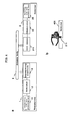
- Figure 1a shows the functional configuration of the communication system related to the embodiment of the present invention.
- the communication system is configured by the transmitter 1 and the receiver 2, which communicate via the antenna body 3.
- the transmitter 1 has the transmitting side data processing unit 11, which generates communication information, which is to be transmitted to the receiver 2, the modulator 12, whichmodulates communication information and outputs it as transmission signals, and the transmitting electrode 13, which applies transmission signals to the antenna body 3.
- the receiver 2 has the signal receiving unit 21, which detects the strength of electric field induced by the antenna body 3 and outputs it as received signals, the demodulator 22, which demodulates the received signals into communication information and the receiving side data processing unit 23, which processes demodulated communication information. Also, the signal receiving unit 21 of the receiver 2 has the receiving electrode 211 and the coil sensor 212.
- the transmitter 1 has the transmitter main frame unit 101, which houses the transmitting side data processing unit 11, the modulator 12 and the transmitting electrode 13, and the band 102, with which the transmitter main frame unit 101 is wrist-worn, as shown in Figure 1c.
- the transmitting electrode 13 is, is mounted on the backside of the main frame unit as covered by the non-conductive cover 103 so that the electrode 13 comes close to the human arm when the transmitter main frame unit 101 is attached to the arm. This configuration ensures that the transmitting electrode 13 and the human body are capacitance-coupled when the transmitter is attached to the human arm.
- the external appearance of the receiver 2 is shown in Figure 1e.
- the receiver 2 has the panel unit 201 housing the receiving electrode 211, and the receiver main frame unit 202 housing the coil sensor 212, the demodulator 22 and the receiving side data processing unit 23.
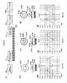
- the receiving electrode 211 is mounted, as shown in the top view of the panel unit 201 in Figure 1f and the cross-sectional view of the panel main frame unit 201 in Figure 1g, on the front side of the panel unit 201 as covered by the non-conductive cover 203 so that the human hand can be held over and come close to the receiving electrode.
- This configuration ensures that the electric field in the vicinity of the human body acts upon the receiving electrode 211 when the human hand is held over the panel unit 201.
- the configuration of the coil sensor 212 of the signal receiving unit 21 of the receiver 2 is schematically shown in Figure 2a.
- the coil sensor 212 has the coil 2121 with its ferrite-made core 2120 being inserted in the central opening, the copper-made sensor electrode 2122 fixed on the end face of the top of the core 2120 and the sealant 2123 with a relatively high magnetic permeability to seal the sensor electrode 2122 on the end face of the core 2120, wherein the sensor 2122 is connected with the receiving electrode 211 via conductive wire.
- the sealant 2123 epoxy resin mixed with magnetic powder and others can be used.
- the coil sensor 212 has the current detecting circuit 2124, which converts the current passing through the coil 2121 to voltage signals.
- this current detecting circuit 2124 is composed of the FET2125, in which the electric current passing through the coil 2121 is used as gate signals, the resistance 2127 for converting source-drain electric current of the FET 2125 passing through having the strength corresponding to the gate signals to electric voltage by the electric power 2126, the condenser 2128 for adjusting the frequency property of the coil condenser 212, and others.
- the communication information generated by the transmitting side dataprocessingunit 11 is AM-modulated by the modulator 12, using, for example, carrier wave with the amplitude of 2V and the frequency of 1MHz, and outputted to the transmitting electrode 13.
- the transmission signals are then applied from the transmitting electrode via capacitance-coupling to a human body.
- the human body functions as the antenna body 3 and induces a static or induced electro-magnetic field, the strength of which corresponds to the transmitting signals, in the vicinity of the human body.
- the electric field in the vicinity of the human body is coupled to the sensor electrode 2122 of the coil condenser 212 via the receiving electrode 211 of the panel unit 201.
- This generates alternate current at the sensor electrode 2122, and then induces a magnetic flux in the central opening of the coil 2121 corresponding to the strength of the electric field in the vicinity of the human body.
- the electric current passes through the coil 2121 corresponding to such changes in the magnetic flux, and this electric current passing through this coil 2121 is converted by the electric current detecting circuit 2124 of the coil sensor 212 to voltage signals and sent as received signals to the demodulator 22.
- the signals corresponding to the electric field in the vicinity of the human body namely the transmission signals of the transmitter 1 can be obtained as the received signal.
- the demodulator 22 demodulates the received signals by AM-demodulation to communication information and transmits the information to the receiving side data processing unit 23. And, the receiving side data processing unit 23 processes the transmitted the communication information.
- the action of the communication system relating to the first embodiment of the present invention has been explained above.
- the sealant 2123 in the coil sensor 212 is provided to improve the sensitivity of detecting the magnetic flux in the coil 2121.
- Figure 3 shows the experiment conducted to demonstrate the effect of this sealant 2123. As shown in Figure 3a, a sign wave with the amplitude of 2V and the frequency of 1MHz is outputted as transmission signals to the transmitting electrode 13.
- the transmission signals are applied from the transmitting electrode 13 via capacitance coupling to one end of the electric wire 302.
- the electric field generated around the electric wire 302 is received by the receiving electrode 211 and coupled to the coil sensor 212.
- the output from the coil sensor 212 is observed with the oscilloscope 303.
- an extremely simple and low-cost configuration of the receiver 2 in which the magnetic flux induced by the electric current generated by the electric field is detected by using the coil 2121, can detect the electric field stably, as compared with the configuration, in which the strength of electric field is detected as the changes in polarization characteristics of electro-optical crystal.
- the coil sensor 212 by connecting the sensor electrode 2122 with each core 2020 as being sandwiched between the cores 2120 of two coils 2121 as shown in Figure 2c, or by connecting the sensor electrode 2122 with each core 2120 as being placed among the cores 2120 of three coils 2121 as shown in Figure 3c, the coil sensor shown above can reduce the magnetic flux, which is escaped into air outside the coil 2121, can more sensitively detect the electric field coupled with the sensor electrode 2122.
- the electric current detecting circuit 2124 individually in each coil and the received signal generation circuit 2200 which generates received signals by adding each output from each electric current detecting circuit 2124.
- Figure 4a shows the functional configuration of the communication system of this embodiment.
- the communication system relating to the second embodiment of the present invention has the same configuration as that of the abovementioned first embodiment except that the receiving electrode 211 of the receiver 2 is removed.
- Figure 4b shows the external configuration of the receiver 2.
- the receiver 2 has a configuration that the coil sensor 212, the demodulator 22 and the receiving side data processing unit 23 are housed in the single case 401. And just under the top surface of such case 401, the coil sensor 212 is placed such that the axis of the coil 2121 becomes perpendicular to the surface.
- the electro-magnetic field in the vicinity of the human body acts upon the coil sensor 212 placed just under the top surface of the case 401, generates electric current passing through the coil 2121.
- the electric current passing through the coil 2121 is then converted by the electric current detecting circuit 2124 of the coil sensor 212 to voltage signals, which are then transmitted to the demodulator 22 as received signals.
- the received signals which correspond to the electro-magnetic field in the vicinity of the human body, namely the transmission signals of the transmitter 1, can be obtained.
- the demodulator 22 then, demodulates the received signals via AM demodulation to communication information, and delivers it to the receiving side data processing unit 23, in which the communication information is processed.
- the second embodiment of the present invention has been explained above. According to the second embodiment of the present invention as explained above, the receiving electrode 211 can be excluded in the first embodiment.
- the third embodiment of the present invention is explained below.
- Figure 5a shows the functional configuration of the communication system of the embodiment of the present invention. As shown in the figure, the communication system according to this embodiment is equipped with the magnetic field detection antenna 501 and the magnetic field strength detecting unit 502 in the signal receiving unit 21 of the receiver 2, in place of the receiving electrode 211 and the coil sensor 212 of the communication system of the aforementioned first embodiment.
- Figure 5b shows the appearance of the receiver 2.
- the receiver 2 has the antenna panel 503, which houses the magnetic field detection antenna 501, and the receiver chassis 504, which houses the magnetic field strength detecting unit 502, the demodulator 22 and the receiving side data processing unit 23.
- Magnetic field detection antenna 501 is of magnetic type, such as loop antenna, for example.
- a human hand can be held over close to the antenna, which is placed inside the panel as it can detect a magnetic flux in vertical direction. Because of this structure, when a human hand is held over the panel unit 201 the magnetic field in the vicinity of the human body acts upon the magnetic field detection antenna 501.
- the magnetic field in the vicinity of the human body acts upon the magnetic field detection antenna 501 placed inside the antenna panel 503 and makes the signals corresponding to the magnetic field pass through the magnetic field detection antenna 501.
- the magnetic field strength detecting unit 502 produces voltage signals indicating the strength of the magnetic field from the electric current passing through this magnetic field detection antenna 501 and sends them to the demodulator 22 as received signals.
- the signals corresponding to the magnetic field in the vicinity of human body, consequently the transmitted signals of the transmitter 1 are obtained as received signals.
- the demodulator 22 demodulates the received signals to communication information by AM demodulation and delivers them to the receiving side data processing unit 23, in which the communication information is processed.
- the magnetic field detection antenna 501 a Hall element, which generates voltage signals corresponding to the magnetic field by the Hall effect, can be used.
- the magnetic field strength detecting unit 502 acts to detect the strength of the magnetic field from voltage signals generated by the Hall element.
- the transmission signals are applied to the human body via capacitance coupling from the transmitting electrode 13, they can be applied to the human body by bringing the transmitting electrode 13 into direct contact with the human body.
- the receiver 2 can be configured to receive signals when a human hand is held over the receiving electrode 21 and coil sensor 212. Alternately, the receiver 2 can be configured to receive signals when a human hand is brought into direct contact with the receiving electrode 211.
- materials other than human body such as animal, plants and other conductive materials, may be used as the antenna 3.
Abstract
Stable receiving action is achieved with a receiver of simpler configuration.
When a human hand is held over the panel unit 201, the electric field in the vicinity of the human body is coupled to the sensor electrode 2122 of the coil sensor 212 from the receiving electrode 211 of the panel unit 201, and alternate current is generated at the sensor electrode 2122. This alternate current then induces a magnetic flux inside the central opening of the coil 2121 in proportion to the strength of the electric field in the vicinity of the human body. Depending on the changes in this magnetic flux, electric current passes through the coil 2121. The electric current passing through the coil 2121 is converted by the electric current detecting circuit 2124 of the coil sensor 212 to voltage signals and transmitted as received signals to the demodulator 22. As a result, the received signals corresponding to the electric field in the vicinity of the human body, namely the transmission signals applied by the transmitter 1 to the human body, are obtained.
Description
- The present invention relates to a communication system using electro-magnetic field for communication. Particularly, it relates to a communication system, which communicates by using electro-magnetic field induced in the human body.
- The communication systems known as using an electro-magnetic field induced in the human body include a communication systems comprising a transmitter, in which voltage signals generated by modulating communication information is applied to the human body by capacitance coupling to induce an electric field in the vicinity of the human body, and a receiver, in which the strength of the electric field induced by the human body is detected and the strength of the electric field is demodulated into communication information (refer to
patent documents - In these communication systems the electric field strength in the receiver is detected by coupling the electric field in the vicinity of the human body with electro-optic crystal via electrode located near the human body as changes in polarization characteristics of the electro-optic crystal (
Patent documents 1 and 2), orfromtheoutputfromFET (FieldEffect Transistor) with its gate connected with the electrodes located under the electric field in the vicinity of the human body (Patent document 3). - [Patent document 1]
Japanese Patent Application Laid-Open Publication No. 2001-298425 - [Patent document 2]
Japanese Patent Application Laid-Open Publication No.2001-352298 - [Patent document 3]
Japanese Patent Application Laid-Open Publication No.2004-282733 - When the technology to detect the electric field strength by means of the aforementioned electro-optic crystal is used, a laser apparatus is necessary, in addition to the electro-optic crystal itself, for measuring polarization characteristics of the electro-optic crystal. Consequently, the receiver will be of complicated structure and more costly.
On the other hand, when the technology to install the FET with a gate connected with the electrode located in the electric field in the vicinity of the human body, the gate voltage is strayed from the FET ground so that it's operating range is not assured. Consequently no stable communications action can be expected.
Also, since the electric field noise generated by various electric products is relatively high in the general environment, any of the aforementioned technology to detect electric field induced in the human body may not ensure stable communications in some cases.
The object of the present invention, therefore, is to achieve stable receiving action in a communication system which conducts communications by using electro-magnetic field generated in the human body, with a simpler receiver configuration. - In order to achieve the foregoing object, the communication system of the present invention comprises a transmitter, which applies transmission signals produced by modulating communication information to a conductive transmission medium and induces an electric field in the vicinity of the aforementioned transmission medium, and a receiver, which detects the strength of the electric field induced by the transmission medium and demodulates the detected electric field strength into the communication information, wherein the receiver is equipped with an electric field detecting unit for detecting the strength of electric field induced by the transmission medium, and the said electric field detecting unit is configured with a receiving electrode, which the transmission medium comes close to or contact during communication between the transmitter and the receiver, a coil(s), a sensor electrode arranged near the central opening of the aforementioned coil, a conductive cable connecting the receiving electrode and the sensor electrode, and a circuit for outputting signals indicating the strength of electric field based on the electric current induced in the coil.
- Such communication system, with a receiver of extremely simple and low-cost configuration, can detect the changes in the electric field strength more stably, than the receiver, in which a magnetic flux induced by the electric current generated by the electric field at the sensor electrode, etc., is detected by using coils, and the strength of electric field is detected as changes in polarization characteristics of electro-optic crystal.
- It is preferable here that such communication system has a magnetic core placed as being inserted in the central opening of the coil in the electric field detecting unit, and that the sensor electrode is placed on the end face of the magnetic core as being adhered to the said end face.
This can improve the sensitivity of the electric field detecting unit. - Also, in this case, for example, the sensor electrode may be equipped with a sealant having a higher magnetic permeability than that of air to seal the entire or periphery of the sensor electrode on the magnetic core.
This may reduce leakage of magnetic flux to the outside of coils and improve the sensitivity of the electric field detecting unit.
Alternately, for example, it is possible that plural pairs made of the magnetic body core and the coil wounded around the said magnetic body are mounted, and the sensor electrode is adhered to the end face of the magnetic core of each aforementioned pair as being sandwiched between (surrounded by) the end faces of the magnetic body core of each pair made of the magnetic body core and the coil wounded around the said magnetic body.
This may also reduce leakage of magnetic flux to the outside of coils and improve the sensitivity of the electric field detecting unit. - Also, in order to achieve the foregoing object, the present invention constitutes the communication system, which comprises a transmitter, which applies transmission signals produced by modulating communication information to the conductive transmission medium and induces an electro-magnetic field in the vicinity of the transmission medium, and a receiver, which detects the strength of the electro-magnetic field induced by the transmission medium and demodulates the detected electro-magnetic field strength into the communication information, wherein the receiver is equipped with an electro-magnetic field detecting unit for detecting the strength of electro-magnetic field induced by the transmission medium, and the said electro-magnetic detecting unit is configured with a coil(s) and a sensor electrode placed near the central opening of the said coil, and which the transmission medium comes close to or contact during communications between the transmitter and the receiver, and a circuit for outputting signals indicating the strength of electro-magneticfieldbased on the electric current generated in the coil.
- The use of such transmission system can realize stable communications in a simpler configuration without using a receiving electrode.
In such communication system, it is also preferable to provide a magnetic body core placed as being inserted into the central opening of the coil of the electro-magnetic field detecting unit, wherein the sensor electrode is placed on the end face of the aforementioned magnetic body core as being adhered to the said end face.
This can further improve the sensitivity of the electro-magnetic strength detecting unit.
Here, the transmission medium in the above communication system can be either human body or living body.
Also, in order to achieve the forgoing object, the present invention constitutes the communication system, comprising a transmitter, which applies transmission signals produced by modulating communication information to a living body and induces a static electro-magnetic field or an induced electro-magnetic field in the vicinity of the living body, and a receiver, wherein the receiver is equipped with a magnetic field detecting unit for detecting the strength of the magnetic field component of the electro-magnetic field induced by the living body, and the magnetic detecting unit is configured with a magnetic field sensor, which the transmission medium comes close to or contact during communications between the transmitter and the receiver, and a magnetic field strength signal generating circuit which outputs signals indicating the strength of the magnetic field component based on the output from the magnetic field sensor. Here, as the magnetic field sensor, a loop antenna can be used, for example. - Since such communication system uses the magnetic field with less ambient noise rather than the electric field, for the transmission from a living body to the receiver, communications will be more stable than that using electric field.
- As mentioned above, the present invention can provide stable receiving action in the communication system, which uses the electro-magnetic field induced in the human body for communications, with a simpler configuration of the receiver.
- An embodiment of the communication system of the present invention is described below with an example of its application to the human body communication system.
To begin with, the first embodiment of this invention is explained. Figure 1a shows the functional configuration of the communication system related to the embodiment of the present invention.
As shown in Figure la, the communication system is configured by thetransmitter 1 and thereceiver 2, which communicate via theantenna body 3.
Also, thetransmitter 1 has the transmitting sidedata processing unit 11, which generates communication information, which is to be transmitted to thereceiver 2, themodulator 12, whichmodulates communication information and outputs it as transmission signals, and the transmittingelectrode 13, which applies transmission signals to theantenna body 3. Thereceiver 2 has thesignal receiving unit 21, which detects the strength of electric field induced by theantenna body 3 and outputs it as received signals, thedemodulator 22, which demodulates the received signals into communication information and the receiving sidedata processing unit 23, which processes demodulated communication information. Also, thesignal receiving unit 21 of thereceiver 2 has the receivingelectrode 211 and thecoil sensor 212. - The external appearance of the
transmitter 1 is shown in Figure 1b.
As shown in the figure, thetransmitter 1 has the transmittermain frame unit 101, which houses the transmitting sidedata processing unit 11, themodulator 12 and the transmittingelectrode 13, and theband 102, with which the transmittermain frame unit 101 is wrist-worn, as shown in Figure 1c. As shown in the cross-sectional view of the transmittermain frame unit 101 in Figure 1d, the transmittingelectrode 13 is, is mounted on the backside of the main frame unit as covered by thenon-conductive cover 103 so that theelectrode 13 comes close to the human arm when the transmittermain frame unit 101 is attached to the arm. This configuration ensures that the transmittingelectrode 13 and the human body are capacitance-coupled when the transmitter is attached to the human arm. - The external appearance of the
receiver 2 is shown in Figure 1e.
As shown in the figure, thereceiver 2 has thepanel unit 201 housing thereceiving electrode 211, and the receivermain frame unit 202 housing thecoil sensor 212, thedemodulator 22 and the receiving sidedata processing unit 23. Thereceiving electrode 211 is mounted, as shown in the top view of thepanel unit 201 in Figure 1f and the cross-sectional view of the panelmain frame unit 201 in Figure 1g, on the front side of thepanel unit 201 as covered by thenon-conductive cover 203 so that the human hand can be held over and come close to the receiving electrode. This configuration ensures that the electric field in the vicinity of the human body acts upon thereceiving electrode 211 when the human hand is held over thepanel unit 201. - Next, the configuration of the
coil sensor 212 of thesignal receiving unit 21 of thereceiver 2 is schematically shown in Figure 2a.
As shown in the figure, thecoil sensor 212 has thecoil 2121 with its ferrite-madecore 2120 being inserted in the central opening, the copper-madesensor electrode 2122 fixed on the end face of the top of thecore 2120 and thesealant 2123 with a relatively high magnetic permeability to seal thesensor electrode 2122 on the end face of thecore 2120, wherein thesensor 2122 is connected with thereceiving electrode 211 via conductive wire. As thesealant 2123, epoxy resin mixed with magnetic powder and others can be used. - Also, the
coil sensor 212 has the current detectingcircuit 2124, which converts the current passing through thecoil 2121 to voltage signals. In the figure, this current detectingcircuit 2124 is composed of the FET2125, in which the electric current passing through thecoil 2121 is used as gate signals, theresistance 2127 for converting source-drain electric current of theFET 2125 passing through having the strength corresponding to the gate signals to electric voltage by theelectric power 2126, thecondenser 2128 for adjusting the frequency property of thecoil condenser 212, and others. - The action of such communication system is explained below.
The communication information generated by the transmittingside dataprocessingunit 11 is AM-modulated by themodulator 12, using, for example, carrier wave with the amplitude of 2V and the frequency of 1MHz, and outputted to the transmittingelectrode 13. The transmission signals are then applied from the transmitting electrode via capacitance-coupling to a human body. The human body functions as theantenna body 3 and induces a static or induced electro-magnetic field, the strength of which corresponds to the transmitting signals, in the vicinity of the human body. - On the other hand, when the human hand is held over the
panel unit 201 in thereceiver 2, the electric field in the vicinity of the human body is coupled to thesensor electrode 2122 of thecoil condenser 212 via thereceiving electrode 211 of thepanel unit 201. This generates alternate current at thesensor electrode 2122, and then induces a magnetic flux in the central opening of thecoil 2121 corresponding to the strength of the electric field in the vicinity of the human body. Then, the electric current passes through thecoil 2121 corresponding to such changes in the magnetic flux, and this electric current passing through thiscoil 2121 is converted by the electriccurrent detecting circuit 2124 of thecoil sensor 212 to voltage signals and sent as received signals to thedemodulator 22. As a result, the signals corresponding to the electric field in the vicinity of the human body, namely the transmission signals of thetransmitter 1, can be obtained as the received signal. - The
demodulator 22 demodulates the received signals by AM-demodulation to communication information and transmits the information to the receiving sidedata processing unit 23. And, the receiving sidedata processing unit 23 processes the transmitted the communication information.
The action of the communication system relating to the first embodiment of the present invention has been explained above.
Here, thesealant 2123 in thecoil sensor 212 is provided to improve the sensitivity of detecting the magnetic flux in thecoil 2121.
Figure 3 shows the experiment conducted to demonstrate the effect of thissealant 2123.
As shown in Figure 3a, a sign wave with the amplitude of 2V and the frequency of 1MHz is outputted as transmission signals to the transmittingelectrode 13. Then, by assuming theelectric wire 302 covered by insulating material as a human body, the transmission signals are applied from the transmittingelectrode 13 via capacitance coupling to one end of theelectric wire 302. And, at the other end of theelectric wire 302, the electric field generated around theelectric wire 302 is received by the receivingelectrode 211 and coupled to thecoil sensor 212. The output from thecoil sensor 212 is observed with theoscilloscope 303. - The results of such experiment have revealed that when no
sealant 2123 was provided as in Figure 3b1, the amplitude of the output from thecoil sensor 212 was 1.10V as shown in Figure 3b2, whereas when thesealant 2123 was mounted to cover only the periphery of thesensor electrode 2122 as shown in Figure 3c1, the amplitude of the output from thecoil sensor 212 was 1.38V as shown in Figure 3c2. When thesealant 2123 was provided to cover theentire sensor electrode 2122 as shown in Figure 3d1, the amplitude of the output from thecoil sensor 212 was 1.48V as shown in Figure 3d2. - And these experiment results indicate that by providing
such sealant 2123 to cover at least a part of thesensor electrode 2122, the magnetic flux detection sensitivity at thecoil 2121 can be improved. The mechanism to improve this magnetic flux detection sensitivity is considered that thesealant 2123 with a relatively high magnetic permeability (higher than that of ambient air at least) can induce the magnetic flux, which may escape into air above thesensor electrode 2122 unless thesealant 2123 is placed, into thecore 2120. - The first embodiment of the present invention has been explained above.
According to the first embodiment of the present invention, an extremely simple and low-cost configuration of thereceiver 2, in which the magnetic flux induced by the electric current generated by the electric field is detected by using thecoil 2121, can detect the electric field stably, as compared with the configuration, in which the strength of electric field is detected as the changes in polarization characteristics of electro-optical crystal. - In the meantime, for example, in the
coil sensor 212, by connecting thesensor electrode 2122 with each core 2020 as being sandwiched between thecores 2120 of twocoils 2121 as shown in Figure 2c, or by connecting thesensor electrode 2122 with each core 2120 as being placed among thecores 2120 of threecoils 2121 as shown in Figure 3c, the coil sensor shown above can reduce the magnetic flux, which is escaped into air outside thecoil 2121, can more sensitively detect the electric field coupled with thesensor electrode 2122. In this case, for example, there should be provided the electric current detectingcircuit 2124 individually in each coil and the receivedsignal generation circuit 2200 which generates received signals by adding each output from each electric current detectingcircuit 2124. - The second embodiment of the present invention is explained below.
Figure 4a shows the functional configuration of the communication system of this embodiment.
As shown in the figure, the communication system relating to the second embodiment of the present invention has the same configuration as that of the abovementioned first embodiment except that the receivingelectrode 211 of thereceiver 2 is removed.
Figure 4b shows the external configuration of thereceiver 2.
As shown in the figure, thereceiver 2 has a configuration that thecoil sensor 212, thedemodulator 22 and the receiving sidedata processing unit 23 are housed in thesingle case 401. And just under the top surface ofsuch case 401, thecoil sensor 212 is placed such that the axis of thecoil 2121 becomes perpendicular to the surface. - With
such receiver 2, when a human hand is held over thecase 401, the electro-magnetic field in the vicinity of the human body acts upon thecoil sensor 212 placed just under the top surface of thecase 401, generates electric current passing through thecoil 2121. The electric current passing through thecoil 2121 is then converted by the electric current detectingcircuit 2124 of thecoil sensor 212 to voltage signals, which are then transmitted to thedemodulator 22 as received signals. As a result, the received signals, which correspond to the electro-magnetic field in the vicinity of the human body, namely the transmission signals of thetransmitter 1, can be obtained. - The
demodulator 22, then, demodulates the received signals via AM demodulation to communication information, and delivers it to the receiving sidedata processing unit 23, in which the communication information is processed.
The second embodiment of the present invention has been explained above.
According to the second embodiment of the present invention as explained above, the receivingelectrode 211 can be excluded in the first embodiment.
The third embodiment of the present invention is explained below.
Figure 5a shows the functional configuration of the communication system of the embodiment of the present invention.
As shown in the figure, the communication system according to this embodiment is equipped with the magneticfield detection antenna 501 and the magnetic fieldstrength detecting unit 502 in thesignal receiving unit 21 of thereceiver 2, in place of the receivingelectrode 211 and thecoil sensor 212 of the communication system of the aforementioned first embodiment.
Figure 5b shows the appearance of thereceiver 2.
As illustrated in the figure, thereceiver 2 has theantenna panel 503, which houses the magneticfield detection antenna 501, and thereceiver chassis 504, which houses the magnetic fieldstrength detecting unit 502, thedemodulator 22 and the receiving sidedata processing unit 23. Themagneticfield detection antenna 501 is of magnetic type, such as loop antenna, for example. As shown in the top view of theantenna panel 503 in Figure 5c and the cross-sectional view of theantenna panel 503 in Figure 5d, a human hand can be held over close to the antenna, which is placed inside the panel as it can detect a magnetic flux in vertical direction. Because of this structure, when a human hand is held over thepanel unit 201 the magnetic field in the vicinity of the human body acts upon the magneticfield detection antenna 501. - According to
such receiver 2, when a human hand is held over theantenna panel 503, the magnetic field in the vicinity of the human body acts upon the magneticfield detection antenna 501 placed inside theantenna panel 503 and makes the signals corresponding to the magnetic field pass through the magneticfield detection antenna 501. The magnetic fieldstrength detecting unit 502 produces voltage signals indicating the strength of the magnetic field from the electric current passing through this magneticfield detection antenna 501 and sends them to thedemodulator 22 as received signals. As a result, the signals corresponding to the magnetic field in the vicinity of human body, consequently the transmitted signals of thetransmitter 1 are obtained as received signals. - The
demodulator 22 demodulates the received signals to communication information by AM demodulation and delivers them to the receiving sidedata processing unit 23, in which the communication information is processed.
As the magneticfield detection antenna 501, a Hall element, which generates voltage signals corresponding to the magnetic field by the Hall effect, can be used. In this case, the magnetic fieldstrength detecting unit 502 acts to detect the strength of the magnetic field from voltage signals generated by the Hall element.
The third embodiment of the present invention has been above explained.
According this third embodiment, since the magnetic field with less ambient noise than that of the electric field is used for the transmission between living body and the receiver, more stable communications than that using the electric field for transmission are achieved.
Although in every embodiment mentioned above, the transmission signals are applied to the human body via capacitance coupling from the transmittingelectrode 13, they can be applied to the human body by bringing the transmittingelectrode 13 into direct contact with the human body.
In the aforementioned first and second embodiments thereceiver 2 can be configured to receive signals when a human hand is held over the receivingelectrode 21 andcoil sensor 212. Alternately, thereceiver 2 can be configured to receive signals when a human hand is brought into direct contact with the receivingelectrode 211.
In all of the above embodiments, materials other than human body, such as animal, plants and other conductive materials, may be used as theantenna 3. -
- [Figure 1] A view showing the configuration of the communication system of the first embodiment of the present invention
- [Figure 2] A view showing the configuration of the coil sensor of the first embodiment of the present invention
- [Figure 3] A view showing the effect of the coil sensor sealant of the first embodiment of the present invention
- [Figure 4] A view showing the configuration of the communication system of the second embodiment of the present invention
- [Figure 5] A view showing the configuration of the communication system of the third embodiment of the present invention
- 1... Transmitter, 2... Receiver, 3... Antenna body, 11... Transmitting side data processing unit, 12... Modulator, 13... Transmitting electrode, 21... Signal receiving unit, 22... Demodulator, 23... Receiving side data processing unit, 101... Transmitter main frame, 102... Band, 201... Panel unit, 202... Receiver main frame unit, 211... Receiving electrode, 212... Coil sensor, 501... Magnetic field detection antenna, 502... Magnetic field strength detecting unit, 503... Antenna panel, 2120... Core, 2121... Coil, 2122... Sensor electrode, 2123... Sealant, 2124... Electric current detecting circuit, 2125... FET, 2126... Power source, 2127... Resistance, 2128... Condenser
Claims (9)
- A communication system comprises a transmitter, which applies transmission signals produced by modulating communication information to the conductive transmission medium and induces an electric field in the vicinity of the transmission medium, and a receiver, which demodulates the detected strength of electric field into communication information,
wherein the receiver has the electric field detecting unit to detect the strength of electric field induced by the transmission medium, and
the electric field detection unit comprises a receiving electrode, which the transmission medium comes close to or contacts during communication between the transmitter and the receiver, coil, a sensor electrode placed close to the central opening of the coil, conductive wire to connect the receiving electrode and the sensor electrode, and an electric field strength signal generating circuit, which outputs signals indicating the strength of electric field based on the electric current induced by the coil. - The communication system according to Claim 1,
wherein the electric field detecting unit has a magnetic body core placed as being inserted in the central opening of the coil and the sensor electrode is placed as being adhered to the end face of the magnetic body core. - The communication system according to Claim 2,
wherein the electric field detecting unit has a sealant with higher magnetic permeability than that of air to seal the entire or periphery of the sensor electrode onto the magnetic body core. - The communication system according to Claim 2,
wherein the electric field detecting unit is equipped with plural pairs of the magnetic body core and the coil wound around the magnetic core body, and the sensor electrode is adhered to the end face of the magnetic body core of the pairs as being sandwiched between (surrounded by) the end face of the magnetic body core of each pair of magnetic body core and the coil wound around the magnetic body. - A communication system comprising a transmitter, which applies transmission signals produced by modulating communication information to the conductive transmission medium and induces an electro-magnetic field in the vicinity of the transmission medium, and a receiver, which detects the strength of electro-magnetic field induced by the transmission medium and demodulates the detected strength of electro-magnetic field into communication information,
wherein the receiver has an electro-magnetic field detecting unit to detect the strength of electro-magnetic field induced by the transmission medium, and the electro-magnetic field detecting unit has a coil, a sensor electrode, which is placed close to the central opening of the coil and which the transmissionmediumcomes close to or contacts during communicationbetween the transmitter and the receiver, and an electro-magnetic field strength signals generating circuit, which outputs signals indicating the strength of electro-magnetic field based on the electric current induced by the coil . - The communication system according to Claim 5,
wherein the electro-magnetic field detecting unit has a magnetic body core placed as being inserted in the central opening of the coil and the sensor electrode is placed as being adhered to the end face of the magnetic body core. - A communication system according to any one of Claims 1, 2, 3, 4, 5 and 6, wherein the transmission medium is a human body or a living body.
- A communication system comprising a transmitter, which applies transmission signals produced by modulating communication information to a living body and induces static electro-magnetic field in the vicinity of living body, and a receiver,
wherein the receiver has the magnetic field detecting unit to detect the strength of the magnetic component of the electro-magnetic field induced by the living body, and
the magnetic field detecting unit has a magnetic sensor to which the transmissionmediumcomes close to or contacts during communication between the transmitter and the receiver, and the magnetic field strength signal generating circuit, which outputs signals indicating the strength of the component of the magnetic field based on the output from the magnetic field sensor. - A communication system according to Claim 6, wherein the magnetic field sensor is a loop antenna.
Applications Claiming Priority (2)
| Application Number | Priority Date | Filing Date | Title |
|---|---|---|---|
| JP2005032527A JP4099484B2 (en) | 2005-02-09 | 2005-02-09 | Communications system. |
| PCT/JP2006/301103 WO2006085438A1 (en) | 2005-02-09 | 2006-01-25 | Communication system |
Publications (1)
| Publication Number | Publication Date |
|---|---|
| EP1848130A1 true EP1848130A1 (en) | 2007-10-24 |
Family
ID=36793016
Family Applications (1)
| Application Number | Title | Priority Date | Filing Date |
|---|---|---|---|
| EP06712298A Withdrawn EP1848130A1 (en) | 2005-02-09 | 2006-01-25 | Communication system |
Country Status (7)
| Country | Link |
|---|---|
| US (1) | US8340575B2 (en) |
| EP (1) | EP1848130A1 (en) |
| JP (1) | JP4099484B2 (en) |
| KR (1) | KR101186450B1 (en) |
| CN (1) | CN101116268B (en) |
| HK (1) | HK1113443A1 (en) |
| WO (1) | WO2006085438A1 (en) |
Cited By (1)
| Publication number | Priority date | Publication date | Assignee | Title |
|---|---|---|---|---|
| CN101604999B (en) * | 2008-06-13 | 2013-01-02 | 三洋电机株式会社 | Communication system and receiver used in communication system |
Families Citing this family (70)
| Publication number | Priority date | Publication date | Assignee | Title |
|---|---|---|---|---|
| EP3827747A1 (en) | 2005-04-28 | 2021-06-02 | Otsuka Pharmaceutical Co., Ltd. | Pharma-informatics system |
| US8802183B2 (en) | 2005-04-28 | 2014-08-12 | Proteus Digital Health, Inc. | Communication system with enhanced partial power source and method of manufacturing same |
| US8730031B2 (en) | 2005-04-28 | 2014-05-20 | Proteus Digital Health, Inc. | Communication system using an implantable device |
| US9198608B2 (en) | 2005-04-28 | 2015-12-01 | Proteus Digital Health, Inc. | Communication system incorporated in a container |
| US8912908B2 (en) | 2005-04-28 | 2014-12-16 | Proteus Digital Health, Inc. | Communication system with remote activation |
| US8836513B2 (en) | 2006-04-28 | 2014-09-16 | Proteus Digital Health, Inc. | Communication system incorporated in an ingestible product |
| JP5714210B2 (en) * | 2005-09-01 | 2015-05-07 | プロテウス デジタル ヘルス, インコーポレイテッド | Implantable wireless communication system |
| JP2009544338A (en) | 2006-05-02 | 2009-12-17 | プロテウス バイオメディカル インコーポレイテッド | Treatment regimen customized to the patient |
| US20080020037A1 (en) * | 2006-07-11 | 2008-01-24 | Robertson Timothy L | Acoustic Pharma-Informatics System |
| JP4814014B2 (en) * | 2006-08-23 | 2011-11-09 | 株式会社カイザーテクノロジー | Electric field detecting device, receiving device and filter amplifier |
| EP2087589B1 (en) * | 2006-10-17 | 2011-11-23 | Proteus Biomedical, Inc. | Low voltage oscillator for medical devices |
| EP2083680B1 (en) | 2006-10-25 | 2016-08-10 | Proteus Digital Health, Inc. | Controlled activation ingestible identifier |
| EP2069004A4 (en) | 2006-11-20 | 2014-07-09 | Proteus Digital Health Inc | Active signal processing personal health signal receivers |
| JP4754508B2 (en) * | 2007-01-31 | 2011-08-24 | 株式会社カイザーテクノロジー | AC signal detector, receiver, and inter-board transmission system |
| ES2930588T3 (en) | 2007-02-01 | 2022-12-19 | Otsuka Pharma Co Ltd | Ingestible Event Marker Systems |
| JP4316670B2 (en) * | 2007-02-09 | 2009-08-19 | アルプス電気株式会社 | Communications system |
| KR101528748B1 (en) | 2007-02-14 | 2015-06-15 | 프로테우스 디지털 헬스, 인코포레이티드 | In-body power source having high surface area electrode |
| EP2124725A1 (en) | 2007-03-09 | 2009-12-02 | Proteus Biomedical, Inc. | In-body device having a multi-directional transmitter |
| US9270025B2 (en) | 2007-03-09 | 2016-02-23 | Proteus Digital Health, Inc. | In-body device having deployable antenna |
| JP4733667B2 (en) * | 2007-04-24 | 2011-07-27 | アルプス電気株式会社 | Communications system |
| US8115618B2 (en) * | 2007-05-24 | 2012-02-14 | Proteus Biomedical, Inc. | RFID antenna for in-body device |
| FI2192946T3 (en) | 2007-09-25 | 2022-11-30 | In-body device with virtual dipole signal amplification | |
| KR101586193B1 (en) | 2007-11-27 | 2016-01-18 | 프로테우스 디지털 헬스, 인코포레이티드 | Transbody communication systems employing communication channels |
| JP5074240B2 (en) * | 2008-03-03 | 2012-11-14 | 株式会社カイザーテクノロジー | AC signal detecting device and receiving device |
| AU2009221781B2 (en) | 2008-03-05 | 2014-12-11 | Otsuka Pharmaceutical Co., Ltd. | Multi-mode communication ingestible event markers and systems, and methods of using the same |
| MY154234A (en) | 2008-07-08 | 2015-05-15 | Proteus Digital Health Inc | Ingestible event marker data framework |
| AU2009281876B2 (en) | 2008-08-13 | 2014-05-22 | Proteus Digital Health, Inc. | Ingestible circuitry |
| KR101192690B1 (en) * | 2008-11-13 | 2012-10-19 | 프로테우스 디지털 헬스, 인코포레이티드 | Ingestible therapy activator system, therapeutic device and method |
| US8055334B2 (en) | 2008-12-11 | 2011-11-08 | Proteus Biomedical, Inc. | Evaluation of gastrointestinal function using portable electroviscerography systems and methods of using the same |
| TWI424832B (en) | 2008-12-15 | 2014-02-01 | Proteus Digital Health Inc | Body-associated receiver and method |
| WO2013012869A1 (en) | 2011-07-21 | 2013-01-24 | Proteus Digital Health, Inc. | Mobile communication device, system, and method |
| US9439566B2 (en) | 2008-12-15 | 2016-09-13 | Proteus Digital Health, Inc. | Re-wearable wireless device |
| US9659423B2 (en) | 2008-12-15 | 2017-05-23 | Proteus Digital Health, Inc. | Personal authentication apparatus system and method |
| EP3395333A1 (en) | 2009-01-06 | 2018-10-31 | Proteus Digital Health, Inc. | Pharmaceutical dosages delivery system |
| JP2012514799A (en) | 2009-01-06 | 2012-06-28 | プロテウス バイオメディカル インコーポレイテッド | Methods and systems for ingestion related biofeedback and individual pharmacotherapy |
| WO2010111403A2 (en) | 2009-03-25 | 2010-09-30 | Proteus Biomedical, Inc. | Probablistic pharmacokinetic and pharmacodynamic modeling |
| CN102458236B (en) | 2009-04-28 | 2016-01-27 | 普罗秋斯数字健康公司 | The Ingestible event marker of high reliability and using method thereof |
| US9149423B2 (en) | 2009-05-12 | 2015-10-06 | Proteus Digital Health, Inc. | Ingestible event markers comprising an ingestible component |
| US8558563B2 (en) | 2009-08-21 | 2013-10-15 | Proteus Digital Health, Inc. | Apparatus and method for measuring biochemical parameters |
| TWI517050B (en) | 2009-11-04 | 2016-01-11 | 普羅托斯數位健康公司 | System for supply chain management |
| UA109424C2 (en) | 2009-12-02 | 2015-08-25 | PHARMACEUTICAL PRODUCT, PHARMACEUTICAL TABLE WITH ELECTRONIC MARKER AND METHOD OF MANUFACTURING PHARMACEUTICAL TABLETS | |
| SG182825A1 (en) | 2010-02-01 | 2012-09-27 | Proteus Biomedical Inc | Data gathering system |
| BR112012025650A2 (en) | 2010-04-07 | 2020-08-18 | Proteus Digital Health, Inc. | miniature ingestible device |
| TWI557672B (en) | 2010-05-19 | 2016-11-11 | 波提亞斯數位康健公司 | Computer system and computer-implemented method to track medication from manufacturer to a patient, apparatus and method for confirming delivery of medication to a patient, patient interface device |
| JP2014504902A (en) | 2010-11-22 | 2014-02-27 | プロテウス デジタル ヘルス, インコーポレイテッド | Ingestible device with medicinal product |
| US9439599B2 (en) | 2011-03-11 | 2016-09-13 | Proteus Digital Health, Inc. | Wearable personal body associated device with various physical configurations |
| US9756874B2 (en) | 2011-07-11 | 2017-09-12 | Proteus Digital Health, Inc. | Masticable ingestible product and communication system therefor |
| WO2015112603A1 (en) | 2014-01-21 | 2015-07-30 | Proteus Digital Health, Inc. | Masticable ingestible product and communication system therefor |
| DE102011085876A1 (en) * | 2011-11-07 | 2013-05-08 | Robert Bosch Gmbh | object locator |
| US9235683B2 (en) | 2011-11-09 | 2016-01-12 | Proteus Digital Health, Inc. | Apparatus, system, and method for managing adherence to a regimen |
| JP5814854B2 (en) | 2012-04-18 | 2015-11-17 | 株式会社東芝 | Communication device |
| US9271897B2 (en) | 2012-07-23 | 2016-03-01 | Proteus Digital Health, Inc. | Techniques for manufacturing ingestible event markers comprising an ingestible component |
| SG11201503027SA (en) | 2012-10-18 | 2015-05-28 | Proteus Digital Health Inc | Apparatus, system, and method to adaptively optimize power dissipation and broadcast power in a power source for a communication device |
| JP2016508529A (en) | 2013-01-29 | 2016-03-22 | プロテウス デジタル ヘルス, インコーポレイテッド | Highly expandable polymer film and composition containing the same |
| JP5941240B2 (en) | 2013-03-15 | 2016-06-29 | プロテウス デジタル ヘルス, インコーポレイテッド | Metal detector device, system and method |
| US11744481B2 (en) | 2013-03-15 | 2023-09-05 | Otsuka Pharmaceutical Co., Ltd. | System, apparatus and methods for data collection and assessing outcomes |
| WO2014151929A1 (en) | 2013-03-15 | 2014-09-25 | Proteus Digital Health, Inc. | Personal authentication apparatus system and method |
| WO2014207337A1 (en) * | 2013-06-24 | 2014-12-31 | Inside Secure | Portable device including means for transmitting data by inductive coupling and intracorporeal current |
| JP2015032927A (en) * | 2013-08-01 | 2015-02-16 | 株式会社東芝 | Biological detection sensor, apparatus including biological detection sensor, and metal detection sensor |
| US9796576B2 (en) | 2013-08-30 | 2017-10-24 | Proteus Digital Health, Inc. | Container with electronically controlled interlock |
| EP3047618B1 (en) | 2013-09-20 | 2023-11-08 | Otsuka Pharmaceutical Co., Ltd. | Methods, devices and systems for receiving and decoding a signal in the presence of noise using slices and warping |
| JP2016537924A (en) | 2013-09-24 | 2016-12-01 | プロテウス デジタル ヘルス, インコーポレイテッド | Method and apparatus for use with electromagnetic signals received at frequencies that are not accurately known in advance |
| US10084880B2 (en) | 2013-11-04 | 2018-09-25 | Proteus Digital Health, Inc. | Social media networking based on physiologic information |
| US11051543B2 (en) | 2015-07-21 | 2021-07-06 | Otsuka Pharmaceutical Co. Ltd. | Alginate on adhesive bilayer laminate film |
| US10706869B2 (en) * | 2016-04-20 | 2020-07-07 | Genelec Oy | Active monitoring headphone and a binaural method for the same |
| CN106199214B (en) * | 2016-06-30 | 2019-11-26 | 联想(北京)有限公司 | A kind of detection device and detection method |
| KR102051875B1 (en) | 2016-07-22 | 2019-12-04 | 프로테우스 디지털 헬스, 인코포레이티드 | Electromagnetic detection and detection of ingestible event markers |
| US10075570B2 (en) * | 2016-08-09 | 2018-09-11 | Microsoft Technology Licensing, Llc | Providing sensing ability with a wireless communication apparatus |
| EP3531901A4 (en) | 2016-10-26 | 2021-01-27 | Proteus Digital Health, Inc. | Methods for manufacturing capsules with ingestible event markers |
| US10698005B2 (en) * | 2017-04-20 | 2020-06-30 | Asahi Kasei Microdevices Corporation | Magnetic detection device, current detection device, method for manufacturing magnetic detection device, and method for manufacturing current detection device |
Family Cites Families (11)
| Publication number | Priority date | Publication date | Assignee | Title |
|---|---|---|---|---|
| JPS60114774A (en) | 1983-11-28 | 1985-06-21 | K T Giken Kk | Electric field detecting apparatus |
| IN174635B (en) * | 1988-03-21 | 1995-01-28 | David William Eli Blatt | |
| JP2542955B2 (en) * | 1990-06-29 | 1996-10-09 | 三洋電機株式会社 | Signal strength peak detection circuit in automatic tuning circuit |
| JP3160685B2 (en) * | 1992-04-14 | 2001-04-25 | 株式会社トーキン | Inductor |
| JP2001076598A (en) * | 1999-09-03 | 2001-03-23 | Omron Corp | Detecting coil and proximity switch using it |
| US20050264427A1 (en) * | 2000-03-03 | 2005-12-01 | The Gov. Of The Usa As Repres. By The Secretary Of The Dept. Of Health And Human Services | Electrical injury protection system |
| JP3898418B2 (en) | 2000-04-13 | 2007-03-28 | 株式会社エヌ・ティ・ティ・ドコモ | Communications system |
| JP3507007B2 (en) | 2000-06-08 | 2004-03-15 | 日本電信電話株式会社 | Transceiver |
| JP2003163444A (en) | 2001-11-28 | 2003-06-06 | Jsr Corp | Printed wiring board and its manufacturing method |
| JP3707463B2 (en) * | 2002-09-20 | 2005-10-19 | ソニー株式会社 | Signal transmission method, signal transmission device, and signal reception device |
| JP4088896B2 (en) | 2003-02-27 | 2008-05-21 | ソニー株式会社 | Communication system and communication apparatus |
-
2005
- 2005-02-09 JP JP2005032527A patent/JP4099484B2/en not_active Expired - Fee Related
-
2006
- 2006-01-25 KR KR1020077020448A patent/KR101186450B1/en not_active IP Right Cessation
- 2006-01-25 US US11/883,363 patent/US8340575B2/en not_active Expired - Fee Related
- 2006-01-25 EP EP06712298A patent/EP1848130A1/en not_active Withdrawn
- 2006-01-25 WO PCT/JP2006/301103 patent/WO2006085438A1/en active Application Filing
- 2006-01-25 CN CN2006800044450A patent/CN101116268B/en not_active Expired - Fee Related
-
2008
- 2008-03-28 HK HK08103493.8A patent/HK1113443A1/en not_active IP Right Cessation
Non-Patent Citations (1)
| Title |
|---|
| See references of WO2006085438A1 * |
Cited By (1)
| Publication number | Priority date | Publication date | Assignee | Title |
|---|---|---|---|---|
| CN101604999B (en) * | 2008-06-13 | 2013-01-02 | 三洋电机株式会社 | Communication system and receiver used in communication system |
Also Published As
| Publication number | Publication date |
|---|---|
| CN101116268A (en) | 2008-01-30 |
| KR101186450B1 (en) | 2012-09-27 |
| CN101116268B (en) | 2012-02-08 |
| JP4099484B2 (en) | 2008-06-11 |
| US20100062709A1 (en) | 2010-03-11 |
| KR20070102606A (en) | 2007-10-18 |
| US8340575B2 (en) | 2012-12-25 |
| WO2006085438A1 (en) | 2006-08-17 |
| HK1113443A1 (en) | 2008-10-03 |
| JP2006222596A (en) | 2006-08-24 |
Similar Documents
| Publication | Publication Date | Title |
|---|---|---|
| US8340575B2 (en) | Communication system | |
| US6869019B1 (en) | Communication device | |
| US20110300801A1 (en) | Radio receiver and transmitter circuits and methods | |
| US20080070499A1 (en) | Magnetic communication through metal barriers | |
| ATE205793T1 (en) | SYSTEM FOR TRANSMITTING AND DETECTING ELECTROMAGNETIC ENERGY | |
| EP0758090A3 (en) | An electromagnetic wave-to-optical signal converting and modulating device and a communication system using the same | |
| JP3979640B2 (en) | Underwater or underground communication device | |
| JP2008053917A (en) | Electric field detector, receiver and filter amplifier | |
| JP2003163644A (en) | Signal transmission system, signal transmitter, and signal receiver | |
| US7425895B2 (en) | Reader device for contactless reading of transponder data | |
| JP2008288758A (en) | Communication system, and transmitter | |
| ATE308762T1 (en) | UNIVERSAL CONNECTING AND RECEIVING DEVICE FOR A MAGNETIC RESONANCE IMAGING DEVICE | |
| US6219529B1 (en) | Wireless communication system using only the magnetic field component | |
| JP5216705B2 (en) | Receiving machine | |
| JP2007243603A (en) | Receiving element and receiving device | |
| JPS6333646B2 (en) | ||
| JP5417376B2 (en) | Receiver | |
| EP0920141A3 (en) | A magnetic vector potential based communications system | |
| JP2516131B2 (en) | Transceiver circuit for ID card system | |
| JP2007184848A (en) | Communication system | |
| JPH0888590A (en) | Wireless data transfer system and constitution of transmission/reception part for wireless data transfer | |
| JP5800352B2 (en) | Communication device and electronic device | |
| JP2004064280A (en) | Portable radio communication system | |
| US20040219960A1 (en) | Contemplation wave communication device | |
| JPS59149432A (en) | Magnetic coupling signal transmitter for rotating mechanism |
Legal Events
| Date | Code | Title | Description |
|---|---|---|---|
| PUAI | Public reference made under article 153(3) epc to a published international application that has entered the european phase |
Free format text: ORIGINAL CODE: 0009012 |
|
| 17P | Request for examination filed |
Effective date: 20070831 |
|
| AK | Designated contracting states |
Kind code of ref document: A1 Designated state(s): DE FR GB |
|
| RBV | Designated contracting states (corrected) |
Designated state(s): DE FR GB |
|
| DAX | Request for extension of the european patent (deleted) | ||
| STAA | Information on the status of an ep patent application or granted ep patent |
Free format text: STATUS: THE APPLICATION HAS BEEN WITHDRAWN |
|
| 18W | Application withdrawn |
Effective date: 20120105 |