EP1847737A2 - Packungsring mit variablem Abstand und positivem Druck sowie Trägeranordnung mit Blattfedern - Google Patents
Packungsring mit variablem Abstand und positivem Druck sowie Trägeranordnung mit Blattfedern Download PDFInfo
- Publication number
- EP1847737A2 EP1847737A2 EP07105590A EP07105590A EP1847737A2 EP 1847737 A2 EP1847737 A2 EP 1847737A2 EP 07105590 A EP07105590 A EP 07105590A EP 07105590 A EP07105590 A EP 07105590A EP 1847737 A2 EP1847737 A2 EP 1847737A2
- Authority
- EP
- European Patent Office
- Prior art keywords
- packing ring
- carrier ring
- carrier
- segment
- segments
- Prior art date
- Legal status (The legal status is an assumption and is not a legal conclusion. Google has not performed a legal analysis and makes no representation as to the accuracy of the status listed.)
- Withdrawn
Links
- 238000012856 packing Methods 0.000 title claims abstract description 188
- 238000007789 sealing Methods 0.000 claims description 15
- 238000000034 method Methods 0.000 claims description 5
- 230000000717 retained effect Effects 0.000 claims description 5
- 230000014759 maintenance of location Effects 0.000 description 11
- 239000012530 fluid Substances 0.000 description 3
- 230000009471 action Effects 0.000 description 2
- 230000005484 gravity Effects 0.000 description 2
- 238000009434 installation Methods 0.000 description 2
- 238000003754 machining Methods 0.000 description 2
- 230000004048 modification Effects 0.000 description 2
- 238000012986 modification Methods 0.000 description 2
- 230000001052 transient effect Effects 0.000 description 2
- 230000015572 biosynthetic process Effects 0.000 description 1
- 230000008859 change Effects 0.000 description 1
- 230000001010 compromised effect Effects 0.000 description 1
- 230000000694 effects Effects 0.000 description 1
- 230000003993 interaction Effects 0.000 description 1
- 230000007246 mechanism Effects 0.000 description 1
- 239000000126 substance Substances 0.000 description 1
- 238000003466 welding Methods 0.000 description 1
Images


Classifications
-
- F—MECHANICAL ENGINEERING; LIGHTING; HEATING; WEAPONS; BLASTING
- F01—MACHINES OR ENGINES IN GENERAL; ENGINE PLANTS IN GENERAL; STEAM ENGINES
- F01D—NON-POSITIVE DISPLACEMENT MACHINES OR ENGINES, e.g. STEAM TURBINES
- F01D11/00—Preventing or minimising internal leakage of working-fluid, e.g. between stages
- F01D11/001—Preventing or minimising internal leakage of working-fluid, e.g. between stages for sealing space between stator blade and rotor
-
- F—MECHANICAL ENGINEERING; LIGHTING; HEATING; WEAPONS; BLASTING
- F16—ENGINEERING ELEMENTS AND UNITS; GENERAL MEASURES FOR PRODUCING AND MAINTAINING EFFECTIVE FUNCTIONING OF MACHINES OR INSTALLATIONS; THERMAL INSULATION IN GENERAL
- F16J—PISTONS; CYLINDERS; SEALINGS
- F16J15/00—Sealings
- F16J15/44—Free-space packings
- F16J15/441—Free-space packings with floating ring
- F16J15/442—Free-space packings with floating ring segmented
Definitions
- This disclosure relates generally to packing rings used in rotary machines, and more particularly to variable clearance, positive pressure packing rings for use in industrial steam turbines.
- seals are provided between rotating and stationary components.
- seals are provided between rotating and stationary components.
- the arcuate packing ring segments typically, four to six per annular seal
- the arcuate packing ring segments are disposed in an annular groove in the stationary component concentric to the axis of rotation of the machine and hence concentric to the sealing surface of the rotating component.
- Each arcuate seal segment carries an arcuate seal face in opposition to the sealing surface of the rotating component.
- the seal faces carry a radially directed array of axially spaced teeth, and which teeth are radially spaced from an array of axially spaced annular teeth forming the sealing surface of the rotating component.
- the sealing function is achieved by creating turbulent flow of a working media, for example, steam, as it passes through the relatively tight clearances within the labyrinth defined by the seal face teeth and the opposing surface of the rotating component.
- variable clearance packing rings may be used as further disclosed, and hereby incorporated by reference, in: GE Docket No. 193439, Cantor Colburn LLP Docket No. GS1-0202, entitled “Variable Clearance Packing Ring Arrangement”; ( US 11/287727 ) GE Docket No. 194777, Cantor Colburn LLP Docket No. GS1-0210, entitled “Apparatus and Method for Steam Turbine Variable Clearance Packing"; and GE Docket No. 193440, Cantor Colburn LLP Docket No.
- the packing ring segments are typically spring biased into outer or large clearance positions causing the seal faces carried by the packing ring to be spaced substantially outwardly of the rotary component.
- the working fluid medium e.g., steam
- the stationary component After start-up, the working fluid medium, e.g., steam, is inlet to the stationary component, creating a pressure differential which urges the segments to move inwardly against the bias of the springs, toward the inner or small clearance positions.
- These springs and corresponding ring components are typically located within the annular groove defined by the stationary housing.
- variable clearance packing rings installation of positive pressure, variable clearance packing rings in existing steam turbines can be a complicated matter which requires field machining or other modification of the rings or of the casing used to mount the rings within the annular groove of the stationary housing. Also, due to circumferential movement of the independent arch segments, retrofitted variable clearance packing rings are prone to archbinding, a condition where an arch segment rides circumferentially over an adjacent segment, jamming the segments in a radially offset position.
- variable clearance positive pressure packing ring which may be easily and simply installed in an annular groove of a stationary component of an existing steam turbine in such manner as to avoid undesired archbinding conditions and excessive extra re-machining of stationary components where retrofit is involved.
- a packing ring assembly including an arcuate carrier ring segment having an aperture formed therethrough, an arcuate packing ring segment including an attachment component extending through the aperture of the carrier ring segment and movably associating the carrier ring segment and the packing ring segment, and an actuator component disposed between the carrier ring segment and the packing ring segment and extending at least partially along the aperture, where the actuator component is configured to maintain the packing ring segment in a first position relative to the carrier ring segment and to allow a movement of the packing ring segment to a second position relative to the carrier ring segment when the packing ring assembly is exposed to a pressure condition.
- a steam turbine including a stationary turbine diaphragm, a rotary turbine shaft disposed within the turbine diaphragm, the turbine diaphragm including an annular groove extending around the turbine shaft, and a packing ring assembly comprising a carrier ring disposed within the annular groove, a plurality of variable clearance arcuate packing ring segments disposed around the turbine shaft in a radially moveable association relative to the carrier, and one or more leaf spring elements configured to maintain the packing ring segments in a first position relative to the carrier ring and to allow a movement of the packing ring segments to a second position relative to the carrier ring when the packing ring assembly is exposed to a pressure condition.
- a method of sealing a rotary machine with a positive pressure variable clearance packing ring assembly including configuring a carrier ring to be received and retained in an annular groove of a stationary diaphragm of the rotary machine, disposing the carrier ring within the annular groove and around a rotary shaft of the rotary machine, connecting a plurality of variable clearance packing ring segments to the carrier ring annularly around the rotary shaft, disposing one or more leaf springs between the packing ring segments and the carrier ring to create a radially moveable association between the packing ring segments and the carrier ring, and maintaining circumferential positions of the plurality of packing ring segments during radially movement of the plurality of packing ring segments.
- a portion of a steam turbine 10 includes a turbine shaft 12 disposed in a stationary turbine diaphragm 14.
- the turbine diaphragm 14 comprises opposing first and second diaphragm halves 16 and 18, respectively.
- a labyrinth seal is provided at the turbine shaft-to-diaphragm interface to prevent leakage.
- the labyrinth seal is formed by the interaction of a positive pressure, variable clearance packing ring assembly 20 and an outer surface of the turbine shaft 12.
- the packing ring assembly 20 is disposed in the turbine diaphragm 14 and is arranged circumferentially about the turbine shaft 12.
- the packing ring assembly 20 is shown illustratively in Figure 1 comprising an annular packing ring 21 composed of six arcuate segments including first, second, and third packing ring segments 22, 24, and 26, respectively, disposed on the lower second diaphragm half 18, and fourth, fifth, and sixth packing ring segments 28, 30, and 32, respectively, disposed on the upper first half 16 of the turbine diaphragm 14.
- the six packing ring segments 22, 24, 26, 28, 30, 32 are described herein by way of example only. Any plurality of ring segments may be used.
- the packing ring assembly 20 may include a total of four arcuate ring segments, two disposed at the first half 16 of the turbine diaphragm and two disposed at the second half 18.
- the various packing ring segments 22, 24, 26, 28, 30, and 32 are disposed in association with a carrier ring 36, as discussed in greater detail below.
- An actuator component 34 such as a spring, is disposed between the packing ring segments 22, 24, 26, 28, 30, 32 and the carrier ring 36 to thus allow movement of the former relative to the latter. See, e.g., Figure 2.
- the carrier ring 36 is disposed in an annular groove 38 of the turbine diaphragm 14 and is comprised, preferably, of a plurality of arcuate carrier ring segments.
- the carrier ring 36 may include, for example, six carrier ring segments which generally correspond in size and disposition to the various packing ring segments 22, 24, 26, 28, 30, and 32.
- one carrier ring segment may be of sufficient size and length so as to correspond to a multiple of packing ring segments, for example, one carrier ring segment may correspond to two packing ring segments.
- the packing ring segments 22, 24, 26, 28, 30, and 32 comprise positive pressure, variable clearance packing ring segments movable between an open outermost large clearance position and a closed innermost small clearance position about the turbine shaft 12 at startup and at speed operations, respectively.
- the packing ring segments 22, 24, 26, 28, 30, and 32 are biased to their open, outermost largest diameter position by the actuator component 34 disposed in association with the carrier ring 36.
- a flowing medium for example, steam
- a flowing medium for example, steam
- the turbine diaphragm 14 and/or the packing ring segments 22, 24, 26, 28, 30, and 32 may include a plurality of passages (not shown) to facilitate introduction and movement of the flowing medium.
- the packing ring assembly 20 delimits horizontal joints 40 and 42 at opposites sides of the turbine diaphragm 14 where the upper first half 16 of the turbine diaphragm 14 meets the lower second half 18. More particularly, the horizontal joints 40, 42 are formed at the intersection of the first and sixth packing ring segments 22 and 32, respectively, and at the intersection of the third and fourth packing ring segments 26 and 28, respectively. As discussed further below, the packing ring segments 22, 32 and 26, 36 (and their corresponding carrier ring segments) terminate respectively at the horizontal joints 40 and 42.
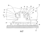
- Figure 2 shows a cross-sectional view of a portion of the steam turbine 10 taken along axis A-A of Figure 1. Particularly, Figure 2 shows the packing ring segment 22 at about mid-length along the segment 22. This view of the packing ring segment 22 is now discussed in detail as being representative of the remaining packing ring segments 24, 26, 28, 30, and 32 which are substantially similar to the segment 22 and thus which are not each discussed in detail herein.
- the packing ring segment 22 includes a sealing face 44 having teeth 46 arranged thereon so as to be opposite from protuberances 48 disposed on the turbine shaft 12.
- the remaining packing ring segments 22, 24, 26, 28, and 30 also include the sealing face 44 and the teeth 46 such that the packing ring 21 delimits a continuous sealing surface circumferentially around the turbine shaft 12.
- the protuberances 48 extend around the circumference of the shaft 12. The teeth 46 and the protuberances 48 serve to form the labyrinth seal during operation of the steam turbine 10.
- the packing ring assembly 20 comprises the carrier ring 36, the actuator component 34, and the annular packing ring 21 formed of the arcuate segments 22, 24, 26, 28, 30, 32.
- the carrier ring 36 is disposed within the annular groove 38 defined by the stationary turbine diaphragm 14.
- the diaphragm 14 includes flanges 50 which give the annular groove 38 a generally dovetail shaped cross-section, as shown in the drawing.
- the annular groove 38 comprises a first portion 52 and a second portion 54, where the first portion 52 is disposed at a radially outer position relative to the second portion 54, and where the second portion 54 is essentially a neck portion having a narrower cross-sectional width as compared to that of the first portion 52.
- the carrier ring 36 is configured to seat within the first portion 52 of the annular groove 38. That is, the segments of the carrier ring 36 are shaped and sized in correspondence with the configuration of the first portion 52 of the annular groove 38 such that the carrier ring 36 is held therein. Particularly, the carrier ring 36 is seated on and/or bears against the flanges 50 of the turbine diaphragm 14.
- the carrier ring 38 may be snap-fit into the first portion 52 of the annular groove 38 and held therein in a snug friction fit. Alternatively and/or additionally, the carrier ring 38 may be fixed at the interior of the annular groove 38 to the turbine diaphragm 14 by any suitable means such as, for example, mounting screws, set screws, etc.
- the carrier ring 36 is disposed in a floating arrangement relative to the annular groove 38. That is, a desired clearance is provided about the carrier ring 36 within the first portion 52 of the groove 52 such that the carrier ring 36 is permitted a slight degree of movement there within.
- the carrier ring 36 is comprised of a plurality of identical arcuate track-like segments each having one or more apertures 56 formed therethrough which allow passage of an attachment component 58, as described in more detail herein.
- Each segment of the carrier ring 36 further includes a plurality of bearing surfaces formed thereon.
- a first bearing surface 60 is disposed on the carrier ring 36 so as to engage the turbine diaphragm 14 at a location generally opposite from the flange 50 of the diaphragm 14.
- the carrier ring 36 includes a second bearing surface 62 disposed in association with the attachment component 58.
- a third bearing surface 63 is disposed in a association with the actuator component 34.
- the carrier ring 36 includes a fourth bearing surface 64 arranged in association with the flange 50 of the turbine diaphragm 14.
- the first and fourth bearing surfaces 60 and 64, respectively, of the carrier ring 36 bear against the annular groove 38 of the turbine diaphragm and serve to retain the carrier 36 therein.
- the fourth bearing surface 64 additionally serves to engage and impede outward radial movement of the packing ring segments 22, 24, 26, 28, 30, and 32, as discussed in detail below.
- the second bearing surface 62 acts as a stop surface with respect to inwardly radial movement of the attachment component 58.
- the third bearing surface 63 of the carrier ring 36 serves as a reaction point for the actuator component 34.
- the first and fourth bearing surfaces 60 and 64 are shaped and sized sufficiently to bear against the annular groove 38 as mentioned above.
- the segments which form the carrier ring 36 are arcuate in shape, thus giving the carrier ring 36 its annular configuration.
- the first and fourth bearing surfaces 60 and 64 are preferably smooth surfaces which extend the length of the segments of the carrier ring 36 generally concentric to one another. In this way, the first and fourth bearing surfaces 60 and 64 are capable of engaging the turbine diaphragm 14 along the length of the segments of the carrier ring 36.
- a plurality of the first and/or fourth bearing surfaces 60, 64 may be sparingly distributed in uniform or random fashion along the length of the packing ring 36 so as to sufficiently engage the turbine diaphragm 14 in order to effect retention of the carrier ring 36 within the annular groove 38.
- the second and third bearing surfaces 62 and 63 may possess any shape and size sufficient to provide bearing surfaces with regard to the actuator component 34 and the attachment component 58, as alluded to above.
- the surface 62 is a continuous smooth surface which extends the length of the segment of the carrier ring 36 concentric with the first bearing surface 60.
- the third bearing surface 63 forms a central region of the segment of the carrier ring 36 , in order to provide a bearing surface for the actuator component 34and further serves to delimit the aperture 56, as shown in Figure 2.
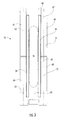
- a first carrier ring segment 37 is disposed adjacent to a second carrier ring segment 77 to form a portion of the carrier ring 36.
- similar additional carrier ring segments are arranged adjacent to the segments 37 and 77 to form the annular carrier ring 36.
- segments 37 and 77 are discussed by way of example.
- the first and second carrier ring segments 37 and 77 are essentially arcuate members, each contain the first, second, third, and fourth bearing surfaces 60, 62, 63, and 64, and a portion of the aperture 56.
- the portion of the aperture 56 is delimited by the third bearing surface 63 and is disposed at one end of each of the segments 37 and 77.
- the portion of the aperture 56 delimited by each carrier ring segment 37 and 77 comprises a portion of an oval such that, when the segments 37 and 77 are adjacently arranged, an elongated complete aperture 56 is formed.
- the aperture 56 is shaped and sized such that an extending component 72 of the packing ring segment 22 passes therethrough.
- the second bearing surface 62 is disposed relative to the aperture 56 in order to bear against an impeding component 70 of the packing ring segment 22 and, as discussed further herein, thus prevents passage thereof through the aperture 56.
- the third bearing surface 63 is configured to support and provide a reaction surface to the actuator component 34.
- the component 34 comprises an elongated spring element which extends on the bearing surface 63 over much of the length of the carrier ring segments 37 and 77.
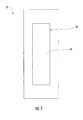
- the carrier ring 36 may be composed of carrier ring segments 39 and 79 as shown in Figure 4.
- the segments 39 and 79 are arcuate members each including two portions of the apertures 56 oppositely disposed as shown in the drawing.
- the third bearing surface 63 delimits the portions of the apertures 56 and extends therebetween as shown in Figure 4.
- the portions of the aperture 56 comprise part of the complete aperture 56 such that when the two carrier ring segments 39 and 79 are adjacently disposed, as in Figure 4, the two aperture portions 56 are arranged adjacent to one another thus forming a complete aperture 56.
- the bearing surfaces 60 and 62 extend the length of the segments 39.
- the carrier ring segments 39 and 79 may be used to form the carrier ring 36 in its entirety.
- the carrier ring 36 may be formed by one or more of the segments 39 and 79 used in combination with one or more of the carrier ring segments 37 and 77 discussed above.
- Each single carrier ring segment 37 and 77 corresponds to one half of the packing ring segments 22, 24, 26, 28, 30, 32.
- a pair of the segments 37 and 77 are required to properly fit one of the packing ring segments 22, 24, 26, 28, 30, 32.
- Each carrier ring segment 39 and 79 interacts with two packing ring segments 22, 24, 26, 28, 30, 32, one at either end of the carrier ring segments 39 and 79.
- a pair of the segments 39 and 79 are required to fit one packing ring segment 22. This is because the aperture 56 which receives and retains the attachment component 58 of the segments 22, 24, 26, 28, 30, 32 is formed by the alignment of a pair of the segments 39 and 79.
- the packing ring segment 22 includes an attachment component 58 which generally comprises a member that operatively connects the packing ring segment 22 and the carrier ring 36 in such manner as to allow radial movement of the packing ring segment 22 and/or the carrier ring 36 relative to one another.
- the attachment member 58 is integrally formed with the packing ring segment 22 and includes an impeding component 70 and an extending component 72.
- the impeding component 70 is shaped and sized accordingly for disposition within the second portion 54 of the annular groove 38 so as to permit radial movement of the attachment component 58 to a certain tolerance and to impede movement beyond such tolerance.
- the impeding component 70 is configured to move radially inwardly and outwardly within the annular groove 38 with respect to the turbine diaphragm 14 and the turbine shaft 12. This radial movement is limited in the inward direction by the second bearing surfaces 62 and in the outward direction by engagement of the packing ring segment 22 with the fourth bearing surface 64 of the carrier ring 36, as discussed in more detail below.
- the impeding component 70 is an elongated arcuate flange-like member which extends at least the length of the aperture 56 (see, Figures 3-4) and has a width which extends beyond the aperture 56, over the bearing surfaces 62.
- the extending component 72 of the attachment component 58 extends from a central area of the impeding component 70 in a direction radially inward relative to the turbine diaphragm 14.
- the extending component is particularly configured to pass through the aperture 56 of the carrier ring segment 22. That is, the extending component 72 is an elongated arcuate member configured to extend approximately the length of the aperture 56 (see, Figures 3-4) and configured to pass through the aperture 56 to permit radial movement of the packing ring segment 22 relative to the carrier ring 36.
- the aperture 56 includes a cross-sectional width which is slightly larger than that of the extending component 72 such that certain circumferential movement of the component 72 is permitted.
- the extending component 72 is formed integrally with the impeding portion 70 such that the extending portion is capable of the radial movement described above.
- the attachment component 58 is a member which is formed integrally with the packing ring segment 22.
- the attachment component 58 comprises a separate member which is selectively attached to the packing ring segment 22.
- the attachment component 58 comprises one or more shoulder bolts where the impeding component 70 is a circular, disk-shaped element and the extending component 72 is a threaded cylindrical member formed integrally with and extending from the impeding member 70.
- the packing ring carrier includes corresponding threaded apertures for receiving and threadingly engaging the extending component 72.
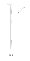
- the actuator component 34 is disposed within the carrier ring 21 proximate to the aperture 56. At a first side, the actuator component 34 contacts the impeding component 70 of the attachment component 58. At an opposite side, the actuator component 34 contacts the third bearing surface 63 of the carrier ring 36.
- the actuator component 34 is a leaf spring which is disposed within the carrier ring 36 on the third bearing surface 63.
- the leaf spring 34 is an elongated arcuate spring element which extends along a length of the carrier ring segments 37, 39, 77, and 79. Preferably, two such leaf springs 34 are disposed in the carrier ring 36, one on either side of the aperture 56.
- the springs 34 extend at least along an entire length of the aperture 56. In this way, the springs 34 are positioned to bear against an entire length of the impeding component 70 of the attachment component 58. In an alternate embodiment, multiple leaf springs 34 may be disposed at either side of the aperture 56.
- the configuration and disposition of the actuator component 34 biases the attachment component 58 radially outward and hence maintains the packing ring segment 22 (which is connected to the attachment component 58 via the extending component 72) in the open outermost large clearance position.
- This position allows a large clearance gap Y (see Figure 1) between the rotary turbine shaft 12 and the sealing face 44 of the packing ring segment 22 when the rotary machine is in a transient condition.
- This "clearance" position is achieved by an outward radial force produced by the reaction of the leaf springs 34 against the third bearing surfaces 63 of the carrier ring 36 where the radial force acts on the impeding component 70 of the attachment component 58 to urge the packing ring segment 22 into the clearance position.
- the actuator component 34 is described herein as comprising leaf springs by way of example only.
- the component 34 may be any actuating device, mechanism, or structure such as but not limited to at least one spring loaded bar, at least one cam, at least one hydraulic cylinder, at least one pneumatic device, at least one piezoelectric device, and at least one sinusoidal spring, etc.
- the packing ring segment 22 is movable from the clearance position to the closed innermost small clearance sealed position, wherein a small clearance gap Z is provided between the turbine shaft 12 and the sealing face 44 of the packing ring segment 22.
- the packing ring segment 22 is moved into this "sealed" position when, during operation of the steam turbine 10, a fluid medium such as steam is inlet into the annular groove 38 of the stationary turbine diaphragm 14 from a high pressure source.
- the fluid medium builds a pressure upon the packing ring segment 22 and inwardly biases the segment 22 against the bias of the actuator component 34, thus moving the packing ring segment 22 towards the rotary turbine shaft 12, and reducing the clearance gap until a seal with the turbine shaft 12 is ultimately formed.
- the packing ring segment 22 is capable of radial movement over a distance X between the open large clearance position and the closed small clearance position.
- the distance X is delimited in the radially inward direction by the reaction of the impeding component 70 against the second bearing surface 62 of the carrier ring 36.
- the distance X is delimited in the radially outward direction by the reaction of the packing ring segments 22-32 against the fourth bearing surface 64 of the carrier ring 36.
- this distance X may be precisely controlled by varying the radial length of the extending component 72 and/or by varying the disposition of the second bearing surface 62 relative to the fourth bearing surface 64.
- an extending component 72 having a greater radial length would allow more travel through the aperture 56 of the carrier ring 36 before contact is made between the packing ring 21 and the second or fourth surface 62, 64 of the carrier ring 36, thus increasing the distance X.
- reducing the radial length of the extending component 72 would allow for less movement of the packing ring 21 relative to the carrier ring 36, thus lessening the distance X.
- the distance X is approximately 0.05 inches to 0.09 inches and is preferably 0.07 inches.
- the actuator component 34 is configured such that the packing ring assembly 20 is retained in the open large clearance position for pressures within the turbine 10 of less than approximately fifty pounds per square inch (psi). For pressures greater than approximately 50psi, the attachment component 58 bears against and compresses the actuator component 34 to thus position the packing ring segment 22 in the closed small clearance position.
- the actuator component 34 forces the impeding component 70 radially outward until the packing ring segment 22 contacts the fourth bearing surface 64 of the carrier ring 36, thus returning the packing ring segment 22 to the outer large clearance position where the segment 22 is maintained until a change of pressure again urges the segment 22 inward.
- the packing ring assembly 20 further includes a retention member 84 at each of the horizontal joints 40 and 42.
- the retention member 84 is generally affixed at the horizontal joints 40 and 42 to the segments of the carrier ring 21 located in the lower second half 18 of the turbine diaphragm 14.
- retention members 84 are affixed to ends of the packing ring segments 22 and 26 proximate to the respective horizontal joints 40 and 42.
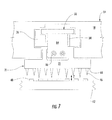
- Figure 7 is a cross-sectional view of the packing ring assembly 20 at the horizontal joint 40 taken along axis B-B of Figure 1. As shown, the retention member 84 extends radially outward from the packing ring segment 22.
- the retention member 84 is connected to the packing ring segment 22 by bolts 86 and extends freely therefrom over the carrier ring 36.
- bolts 86 extends freely therefrom over the carrier ring 36.
- the retention member 84 may be welded to the packing ring segment 22, formed integrally therewith, etc.
- the retaining member 84 serves to position and to maintain the position of the packing ring segment 22 relative to the carrier ring 36 in order to prevent an archbound condition.
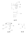
- Figure 8 shows an isolated view of one side of the carrier ring 36 of Figure 7.
- Figure 9 is a partial view of the side of the carrier ring 36 taken from axis C-C of Figure 8. From these views, it is apparent that the portion of the carrier ring 36 which delimits the third bearing surface 63 is set back circumferentially relative to the portions of the carrier 36 which form the bearing surfaces 60 and 62. This set back arrangement delimits a recess 88 configured to receive the retaining member 84.
- the retaining member 84 extends radially outward from the packing ring segment 22 and is received and retained in the recess 88 of the carrier ring 36, as best shown in Figures 3 and 11.
- the retaining member 84 secures the packing ring segment 22 on the corresponding segment of the carrier ring 36 and prevents circumferential movement of the former relative to the latter. That is, the retaining member 84 holds the packing ring segment 22 in a fixed circumferential position relative to the carrier ring segment and thus prevents gravity induced circumferential downward movement of the packing ring segment 22. This ensures that, during operation of the steam turbine 10, the packing ring segment 22 does not slip downward and ride over or under the adjacent packing ring segment 24 into an archbound position.
- the retention member 84 allows for radial movement of the packing ring segment 22 to allow for variable clearance of the packing ring 21 but yet inhibits circumferential movement of the segment 22.
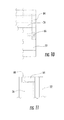
- Figure 12 shows a cross-sectional view of the carrier ring assembly 20 taken from the axis D-D of Figure 1. That is, this view shows the packing ring segment 28 at the horizontal joint 42.
- the retention member 84 is not utilized on the segments 28 and 32.
- a set screw 90 is used to retain the carrier ring 36 within the annular groove 38 of the turbine diaphragm 14. This is particularly advantageous during initial fitting of the segments of the carrier ring 36 within the groove 38 in order to maintain the carrier segments in the upper half of the annular groove 38 during installation of the packing ring assembly 20.
- the packing ring assembly 20 further includes a securing member 92 attached to the carrier ring 36 by way of additional bolts 86.
- the securing member 92 secures the actuator component 34 and the attachment component 58 of the packing ring segment 28 within the carrier ring 34 and prevents the same from gravity induced downward movement.
- the carrier ring 36 at the horizontal joint 42 comprises a recess 89 for receiving the securing member 92.
- the recess 89 is delimited by a circumferential extension of a part of the carrier ring 36 which forms the first bearing surface 60.
- the portion of the carrier ring 36 which delimits the surface 60 extends circumferentially further than the portions of the carrier ring 36 which form the second and third bearing surfaces 62 and 63.
- This extension delimits the recess 89, as can be seen in Figures 14 and 15.
- the securing member 92 extends in the recess 89 between opposite sides of the carrier ring 36.
- the packing ring segment 32 at the horizontal joint 40 appears substantially similar to the segment 28 discussed above with reference to Figures 12-15. That is, the packing ring segment 32 includes the set screw 90 and the securing member 92. Therefore, the segment 32 is not shown or discussed herein in detail, instead reference is made to the packing ring segment 28.
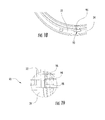
- the packing ring assembly 20 further includes an alignment arrangement 93 disposed between adjacent packing ring segments 22 and 24, segments 24 and 26, segments 28 and 30, and segments 30 and 32. That is, the alignment arrangement 93 is utilized between all packing ring segments 22, 24, 26, 28, 30, and 32 except at the horizontal joints 40 and 42.
- the alignment arrangement 93 comprises an arrangement which provides for proper radial movement of the packing ring segments 22, 24, 26, 28, 30, and 32 but which does not allow undesirable misalignment thereof.
- the alignment arrangement 93 comprises a key 94 which is fixed to and which extends circumferentially from one of a pair of adjacent packing ring segments.
- the key 94 is fixed in the packing ring segment 22 and partially extends therefrom.
- the key 94 may be disposed within in an aperture 96 of the segment 22 by a friction fit, via a set screw, via welding, etc.
- the key 94 may be formed integrally with the segment 22.
- the portion of the key 94 extending from the packing ring segment 22 is received within an aperture 98 of the adjacent packing ring segment 24.
- the aperture 98 has a larger cross-sectional area than that of the extending portion of the key 94 such that the key 94 may move slightly within the aperture 98.
- This arrangement circumferentially associates the adjacent packing ring segments 22 and 24 in order to avoid archbinding thereof but yet permits desired radial movement of the segments 22 and 24 to provide for the pressure induced variable clearance positioning thereof.
Landscapes
- Engineering & Computer Science (AREA)
- General Engineering & Computer Science (AREA)
- Mechanical Engineering (AREA)
- Turbine Rotor Nozzle Sealing (AREA)
Applications Claiming Priority (1)
| Application Number | Priority Date | Filing Date | Title |
|---|---|---|---|
| US11/399,719 US7384235B2 (en) | 2006-04-07 | 2006-04-07 | Variable clearance positive pressure packing ring and carrier arrangement with leaf springs |
Publications (1)
| Publication Number | Publication Date |
|---|---|
| EP1847737A2 true EP1847737A2 (de) | 2007-10-24 |
Family
ID=38222754
Family Applications (1)
| Application Number | Title | Priority Date | Filing Date |
|---|---|---|---|
| EP07105590A Withdrawn EP1847737A2 (de) | 2006-04-07 | 2007-04-04 | Packungsring mit variablem Abstand und positivem Druck sowie Trägeranordnung mit Blattfedern |
Country Status (4)
| Country | Link |
|---|---|
| US (1) | US7384235B2 (de) |
| EP (1) | EP1847737A2 (de) |
| JP (1) | JP2007292068A (de) |
| CN (1) | CN101135248B (de) |
Cited By (1)
| Publication number | Priority date | Publication date | Assignee | Title |
|---|---|---|---|---|
| WO2014143237A1 (en) * | 2013-03-12 | 2014-09-18 | Dierksmeier Douglas D | Active seal system and method of operating a turbomachine |
Families Citing this family (12)
| Publication number | Priority date | Publication date | Assignee | Title |
|---|---|---|---|---|
| US8540479B2 (en) * | 2007-01-11 | 2013-09-24 | General Electric Company | Active retractable seal for turbo machinery and related method |
| US7909335B2 (en) * | 2008-02-04 | 2011-03-22 | General Electric Company | Retractable compliant plate seals |
| US20120027582A1 (en) | 2010-08-02 | 2012-02-02 | General Electric Company | Floating packing ring assembly |
| US8628092B2 (en) | 2010-11-30 | 2014-01-14 | General Electric Company | Method and apparatus for packing rings |
| US8794918B2 (en) | 2011-01-07 | 2014-08-05 | General Electric Company | System for adjusting brush seal segments in turbomachine |
| US9121297B2 (en) | 2011-03-28 | 2015-09-01 | General Electric Company | Rotating brush seal |
| US9255486B2 (en) | 2011-03-28 | 2016-02-09 | General Electric Company | Rotating brush seal |
| US9920644B2 (en) * | 2013-02-20 | 2018-03-20 | Siemens Aktiengesellschaft | Riffled seal for a turbomachine, turbomachine and method of manufacturing a riffled seal for a turbomachine |
| JP6379997B2 (ja) * | 2014-10-24 | 2018-08-29 | 浜名湖電装株式会社 | 流体制御弁装置 |
| US20220178266A1 (en) * | 2020-12-04 | 2022-06-09 | General Electric Company | Fast response active clearance control system with piezoelectric actuator |
| CN113027539B (zh) * | 2021-03-16 | 2022-11-25 | 中国联合重型燃气轮机技术有限公司 | 燃气轮机和用于燃气轮机的旋转阻尼密封 |
| US12404779B1 (en) * | 2024-02-20 | 2025-09-02 | Ge Infrastructure Technology Llc | Axially adjustable inserted ring within packing ring and method of using same |
Family Cites Families (14)
| Publication number | Priority date | Publication date | Assignee | Title |
|---|---|---|---|---|
| US3529906A (en) * | 1968-10-30 | 1970-09-22 | Westinghouse Electric Corp | Static seal structure |
| US5002288A (en) * | 1988-10-13 | 1991-03-26 | General Electric Company | Positive variable clearance labyrinth seal |
| JPH04187801A (ja) * | 1990-11-21 | 1992-07-06 | Hitachi Ltd | タービンのシール部間隙調整装置 |
| US5374068A (en) * | 1991-05-07 | 1994-12-20 | General Electric Co. | Method for providing uniform radial clearance of labyrinth seals between rotating and stationary components |
| US5603510A (en) * | 1991-06-13 | 1997-02-18 | Sanders; William P. | Variable clearance seal assembly |
| US5362072A (en) * | 1992-12-21 | 1994-11-08 | Imo Industries, Inc., Quabbin Division | Turbine radial adjustable labyrinth seal |
| US5709388A (en) * | 1996-09-27 | 1998-01-20 | General Electric Co. | Variable clearance packing ring with guide for preventing circumferential displacement |
| US6065754A (en) * | 1998-04-15 | 2000-05-23 | General Electric Co. | Uniform clearance, temperature responsive, variable packing ring |
| JP3358994B2 (ja) * | 1998-09-24 | 2002-12-24 | 三菱重工業株式会社 | ターボ回転機械の自動調整シール |
| JP2002070505A (ja) * | 2000-08-30 | 2002-03-08 | Toshiba Corp | ターボ機械のシール部隙間調整装置 |
| US6840519B2 (en) * | 2001-10-30 | 2005-01-11 | General Electric Company | Actuating mechanism for a turbine and method of retrofitting |
| US6572115B1 (en) * | 2001-12-21 | 2003-06-03 | General Electric Company | Actuating seal for a rotary machine and method of retrofitting |
| US6655696B1 (en) * | 2002-06-28 | 2003-12-02 | General Electric Company | Seal carrier for a rotary machine and method of retrofitting |
| US7229246B2 (en) * | 2004-09-30 | 2007-06-12 | General Electric Company | Compliant seal and system and method thereof |
-
2006
- 2006-04-07 US US11/399,719 patent/US7384235B2/en not_active Expired - Fee Related
-
2007
- 2007-04-04 EP EP07105590A patent/EP1847737A2/de not_active Withdrawn
- 2007-04-05 JP JP2007099052A patent/JP2007292068A/ja active Pending
- 2007-04-09 CN CN2007101097979A patent/CN101135248B/zh not_active Expired - Fee Related
Cited By (1)
| Publication number | Priority date | Publication date | Assignee | Title |
|---|---|---|---|---|
| WO2014143237A1 (en) * | 2013-03-12 | 2014-09-18 | Dierksmeier Douglas D | Active seal system and method of operating a turbomachine |
Also Published As
| Publication number | Publication date |
|---|---|
| US20070237623A1 (en) | 2007-10-11 |
| CN101135248B (zh) | 2011-04-06 |
| JP2007292068A (ja) | 2007-11-08 |
| US7384235B2 (en) | 2008-06-10 |
| CN101135248A (zh) | 2008-03-05 |
Similar Documents
| Publication | Publication Date | Title |
|---|---|---|
| EP1847737A2 (de) | Packungsring mit variablem Abstand und positivem Druck sowie Trägeranordnung mit Blattfedern | |
| US7704041B2 (en) | Variable clearance positive pressure packing ring and carrier arrangement with coil type spring | |
| CA2354261C (en) | Soft bearing support | |
| US7344357B2 (en) | Methods and apparatus for assembling a rotary machine | |
| EP1860356B1 (de) | Verfahren und Vorrichtung zur Dichtung mit variablen Abständen | |
| JP4117927B2 (ja) | 回転機械 | |
| EP4299964A2 (de) | Drehverbindung mit mehreren durchgängen | |
| CN104220769B (zh) | 具有内部面密封表面的旋转卡盘密封件 | |
| CN101054909B (zh) | 蒸汽涡轮机可变间隙填塞件 | |
| EP0950798A2 (de) | Auf Temperatur ansprechender Dichtring mit gleichbleibendem Spiel | |
| GB2439635A (en) | A variable clearance packing ring for a seal | |
| US6022027A (en) | Variable clearance packing ring with clips for preventing circumferential displacement | |
| US6651986B2 (en) | Retractable packing ring lower half segment retaining key and method for retaining retractable packing ring lower half segment | |
| US8794633B2 (en) | Leaf seal | |
| CA2793080C (en) | Brush ring seal | |
| EP1790886B1 (de) | Dichtring mit variablem Radialspiel | |
| US20070257445A1 (en) | Tension Spring Actuators for Variable Clearance Positive Pressure Packings for Steam Turbines | |
| US11287043B2 (en) | High clearance seal assembly | |
| EP1890060A1 (de) | Packungsring mit variablem Abstand | |
| CN102341628A (zh) | 用于涡轮机的迷宫式密封衬套和用于安装具有迷宫式密封衬套的迷宫式密封装置的方法 | |
| US20070120329A1 (en) | Apparatus and method for steam turbine variable clearance packing | |
| GB2297363A (en) | Ring seal |
Legal Events
| Date | Code | Title | Description |
|---|---|---|---|
| PUAI | Public reference made under article 153(3) epc to a published international application that has entered the european phase |
Free format text: ORIGINAL CODE: 0009012 |
|
| AK | Designated contracting states |
Kind code of ref document: A2 Designated state(s): AT BE BG CH CY CZ DE DK EE ES FI FR GB GR HU IE IS IT LI LT LU LV MC MT NL PL PT RO SE SI SK TR |
|
| AX | Request for extension of the european patent |
Extension state: AL BA HR MK YU |
|
| STAA | Information on the status of an ep patent application or granted ep patent |
Free format text: STATUS: THE APPLICATION IS DEEMED TO BE WITHDRAWN |
|
| 18D | Application deemed to be withdrawn |
Effective date: 20121101 |