EP1847424A1 - Self-locking winder for an automobile seat belt and safety system comprising such a winder - Google Patents
Self-locking winder for an automobile seat belt and safety system comprising such a winder Download PDFInfo
- Publication number
- EP1847424A1 EP1847424A1 EP07290489A EP07290489A EP1847424A1 EP 1847424 A1 EP1847424 A1 EP 1847424A1 EP 07290489 A EP07290489 A EP 07290489A EP 07290489 A EP07290489 A EP 07290489A EP 1847424 A1 EP1847424 A1 EP 1847424A1
- Authority
- EP
- European Patent Office
- Prior art keywords
- torsion bar
- additional
- airbag
- winder
- predetermined
- Prior art date
- Legal status (The legal status is an assumption and is not a legal conclusion. Google has not performed a legal analysis and makes no representation as to the accuracy of the status listed.)
- Granted
Links
Images


Classifications
-
- B—PERFORMING OPERATIONS; TRANSPORTING
- B60—VEHICLES IN GENERAL
- B60R—VEHICLES, VEHICLE FITTINGS, OR VEHICLE PARTS, NOT OTHERWISE PROVIDED FOR
- B60R22/00—Safety belts or body harnesses in vehicles
- B60R22/34—Belt retractors, e.g. reels
- B60R22/341—Belt retractors, e.g. reels comprising energy-absorbing means
- B60R22/3413—Belt retractors, e.g. reels comprising energy-absorbing means operating between belt reel and retractor frame
-
- B—PERFORMING OPERATIONS; TRANSPORTING
- B60—VEHICLES IN GENERAL
- B60R—VEHICLES, VEHICLE FITTINGS, OR VEHICLE PARTS, NOT OTHERWISE PROVIDED FOR
- B60R22/00—Safety belts or body harnesses in vehicles
- B60R22/28—Safety belts or body harnesses in vehicles incorporating energy-absorbing devices
- B60R2022/286—Safety belts or body harnesses in vehicles incorporating energy-absorbing devices using deformation of material
- B60R2022/287—Safety belts or body harnesses in vehicles incorporating energy-absorbing devices using deformation of material of torsion rods or tubes
-
- B—PERFORMING OPERATIONS; TRANSPORTING
- B60—VEHICLES IN GENERAL
- B60R—VEHICLES, VEHICLE FITTINGS, OR VEHICLE PARTS, NOT OTHERWISE PROVIDED FOR
- B60R22/00—Safety belts or body harnesses in vehicles
- B60R22/34—Belt retractors, e.g. reels
- B60R22/36—Belt retractors, e.g. reels self-locking in an emergency
-
- B—PERFORMING OPERATIONS; TRANSPORTING
- B60—VEHICLES IN GENERAL
- B60R—VEHICLES, VEHICLE FITTINGS, OR VEHICLE PARTS, NOT OTHERWISE PROVIDED FOR
- B60R22/00—Safety belts or body harnesses in vehicles
- B60R22/34—Belt retractors, e.g. reels
- B60R22/46—Reels with means to tension the belt in an emergency by forced winding up
Definitions
- the present invention relates to a self-locking retractor for a seat belt of a motor vehicle, comprising a winding spool rotatably mounted in a housing and a stepped stress limiter with a torsion bar mounted by one of its two opposite ends on one axis of the winding spool and the other end on a locking means controlled by a parameter of the vehicle and / or the seat belt.
- the present invention also relates to a safety system for the passengers of a motor vehicle with at least one airbag mounted in front of a passenger and a self-locking retractor for a seat belt of a motor vehicle as described above.
- stepped limiting devices as described for example in the document US-A-6,592,064 , comprise a traditional torsion bar and an additional steel constrictor element which bends or breaks to admit a point load of a certain amplitude in connection with a load or stress limiter formed by a traditional torsion bar.
- the object of the invention is to provide a self-locking winder of the type described in the introduction, which does not have the limited characteristics of the reels traditionally used.
- the invention should provide a safety system comprising an inflated cushion and an improved winder so that the use of the inflated cushion and the seat belt is optimized.
- the invention should make it possible to obtain a safety system with a kinetic energy absorption system of a passenger, in which the airbag and the self-locking reel co-operate essentially in a predictable and predetermined manner.
- a self-locking winder for a seat belt of a motor vehicle comprising a winding spool rotatably mounted in a housing and a torsion bar torsion limiter mounted by one of its two opposite ends on one axis of the winding spool and the other end on a controlled blocking means by a parameter of the vehicle and / or the seat belt.
- the torsion bar is a limiter with two stress levels comprising torsion bar main limiting means and, axially aligned with them, additional stress limiting means mounted by their outer end on an element. locked in rotation in a predetermined situation.
- the object of the invention is also achieved with a safety system for the passengers of a motor vehicle with at least one airbag mounted in front of a passenger and a reel as described above.
- the system is shaped so that the additional limiting means breaks at a predetermined torque angle depending on the inflation of the airbag and so that the airbag absorbs a significant portion of the passenger's energy in the event of an accident.
- the present invention relates to a safety system for the passengers of a motor vehicle with a self-locking retractor of a safety belt and an airbag.
- a safety system for the passengers of a motor vehicle with a self-locking retractor of a safety belt and an airbag.
- Figure 1 shows a driver retained by a seat belt 1 on a seat 2 in front of a steering wheel 3.
- the driver's movement attached with the seat belt is idle first by the self-locking retractor until the airbag 6 is fully inflated as shown by the broken line 6.
- the self-locking winder of the invention comprises load-step limiting means described in more detail hereinafter, in particular with reference to FIG. 2.
- the winder is designed to to ensure that a relatively large portion of the kinetic energy of the passenger will be absorbed by the airbag that ensures contact with the passenger body on a large enough surface while the interaction between the seat belt and passenger passenger around the shoulder should be considered almost punctual.
- the self-locking retractors can be adapted, for example, to ensure optimal absorption of kinetic energy between the seat belt and the airbag.
- the retractor proposed by the invention makes it possible to obtain different proportions of absorption according to the geometrical data of the interior space of the vehicle and according to the needs of the passengers.
- Figures 2 and 3 show two different ways and in more detail, a self-locking winder according to the invention.
- a self-locking retractor for a seat belt of a motor vehicle essentially comprises a winding shaft or winding spool 8 for the safety belt 1, rotatably mounted in a housing 7, and a stress limiter two-level torsion bar 9 which concentrically extends inside the coil 8 and comprises a main portion 10 of the stress limiter of the torsion bar and, axially aligned with this main portion 10, a limiter
- the standard portion 10 of the torsion bar is provided, at its outer end, with a head member 12 non-rotatably mounted in a threaded profiled head 13 which cooperates with a parameter-controlled locking means. of the motor vehicle and / or the seat belt, as described, for example, in the document WO 96/32303 .
- the connecting head 12 may be in the form of a pinion.
- the main part 10 of the torsion bar which can be considered as a primary torsion bar, is fixed on the other end, the inner end, by a connecting head 15 in the form of a pinion, so non-rotating in the winding coil 8 of the seat belt.
- the secondary or additional stress limiter 11 is made in one piece with the torsion bar primary portion 10 and shares with it the connection head 15.
- free outer end 16 of the abutment 11 is in the form of a connection head non-rotatably mounted in a termination piece 18.
- the connection head 16 may have a radially outer profile of a pinion.
- connection head 15 which is in common with the primary part and the secondary part of the bar, and the connection head 16 of the free end is shaped so as to form a breakable portion 19 whose function will be explained below.
- the termination head or cover 18 comprises an end 20 in the form of a flange rotatably engaged in the coil 8.
- a pre-tensioning pyrotechnic device 21 applies a torque to the cover 18, as described, for example, in the document US-A-6,241,172 .
- FIGS. 2 and 4 to 6 show various embodiments of the additional load limiter 11, in that FIGS. 2 and 4 relate to a two-level torsion bar load limiter in one piece and FIGS. rooms.
- the additional or secondary load limiter 11 which is made in one piece with the primary torsion bar 10, is a tubular bar portion having a predetermined inner diameter and a predetermined thickness. .
- FIG. 4 shows an embodiment in which the additional load limiter 11 is formed by a torsion bar which does not comprise an axial hole but which comprises a predetermined annular groove 22 whose diameter is determined as a function of the angle of twist and breakage sought.
- FIGS. 5 and 6 show another embodiment of the additional or auxiliary load limiter in two different variants which are distinguished by the fact that the additional or auxiliary load limiter is in the form of a separate torsion bar 24 axially aligned with the main torsion bar 25 and which is fixed by its outer end 27 non-rotatively to the cover 18, the portion between the heads 26 and 27 constituting the breakable portion of the bar.
- the torsion bar 25 is connected by non-rotating connectors 28 and 29 respectively to the coil 8 and to the threaded head 13.
- the secondary torsion bar 24 does not comprise an axial hole, whereas in the variant shown in FIG. 6, the bar representing the secondary part comprises an axial hole 30.
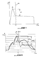
- Figure 7 shows the manner in which the winder and an airbag cooperate and more particularly indicates the torque T acting on the torsion bar as a function of the torsion angle ⁇ .
- the curve shown in this diagram corresponds to the embodiment with a tubular torsion bar.
- the steep slope is determined by the pre-tensioning pyrotechnic device winding the belt and holding the passenger thus on his seat, and by the combination of the load limiting means of the primary and secondary torsion bars to reach the maximum value (T k ) at which the additional torsion bar breaks.
- ⁇ T stepped change
- AB indicates the angle of torsion ⁇ i of the intervention of the airbag. Up to this angle ⁇ i , the load is taken into account by the two-level torsion bar system. It should be noted that the airbag intervenes advantageously at the end of the gradual change of the load.
- angle ⁇ i at which the airbag intervenes, varies according to the belts of security considered and according to the designs of the vehicles.
- Figure 8 shows the load on a safety belt passing through the shoulder as a function of the time elapsed in an accident.
- Curve A relates to a device traditionally used and curve B relates to the winder according to the invention.
- the line AB indicates the moment T i at which the airbag intervenes to take over the absorption of the kinematic energy of the passenger.
- the slope of curve B is more regular.
- the load on the belt is therefore optimal for the passenger attached.
- the torsion bar two-level load limiting means according to the invention provide the advantage over traditional designs of a longer duration of the maximum value BLm and a much larger change of the graduated change ⁇ BL. the load acting on the seat belt followed by a relatively lower and substantially constant load value on the belt passing through the shoulder, as determined by the primary portion of the torsion bar.
Abstract
Description
La présente invention concerne un enrouleur autobloquant pour une ceinture de sécurité d'un véhicule automobile, comprenant une bobine d'enroulement montée en rotation dans un boîtier et un limiteur étagé de contraintes avec une barre de torsion montée par une de ses deux extrémités opposées sur un axe de la bobine d'enroulement et par l'autre extrémité sur un moyen de blocage commandé par un paramètre du véhicule et/ou de la ceinture de sécurité. La présente invention concerne également un système de sécurité pour les passagers d'un véhicule automobile avec au moins un coussin gonflable monté devant un passager et un enrouleur autobloquant pour une ceinture de sécurité d'un véhicule automobile comme décrit ci avant.The present invention relates to a self-locking retractor for a seat belt of a motor vehicle, comprising a winding spool rotatably mounted in a housing and a stepped stress limiter with a torsion bar mounted by one of its two opposite ends on one axis of the winding spool and the other end on a locking means controlled by a parameter of the vehicle and / or the seat belt. The present invention also relates to a safety system for the passengers of a motor vehicle with at least one airbag mounted in front of a passenger and a self-locking retractor for a seat belt of a motor vehicle as described above.
Traditionnellement, des dispositifs limiteurs étagés, tels que décrits par exemple dans le document
Le désavantage du dispositif connu du document
En ce qui concerne le système de sécurité pour les passagers d'un véhicule automobile, système qui comprend au moins un coussin gonflable et un enrouleur autobloquant comme décrit ci avant, la demande internationale
Le but de l'invention est de proposer un enrouleur autobloquant du type décrit en introduction, qui ne présente pas les caractéristiques limitées des enrouleurs traditionnellement utilisés.The object of the invention is to provide a self-locking winder of the type described in the introduction, which does not have the limited characteristics of the reels traditionally used.
Avantageusement, l'invention devrait proposer un système de sécurité comprenant un coussin gonflé et un enrouleur amélioré de manière que l'utilisation du coussin gonflé et de la ceinture de sécurité soit optimisée.Advantageously, the invention should provide a safety system comprising an inflated cushion and an improved winder so that the use of the inflated cushion and the seat belt is optimized.
L'invention devrait enfin permettre d'obtenir un système de sécurité avec un système d'absorption d'énergie cinétique d'un passager, dans lequel le coussin gonflable et l'enrouleur autobloquant coopèrent essentiellement d'une manière prévisible et prédéterminée.Finally, the invention should make it possible to obtain a safety system with a kinetic energy absorption system of a passenger, in which the airbag and the self-locking reel co-operate essentially in a predictable and predetermined manner.
Le but de l'invention est atteint avec un enrouleur autobloquant pour une ceinture de sécurité d'un véhicule automobile, comprenant une bobine d'enroulement montée en rotation dans un boîtier et un limiteur étagé de contrainte à barre de torsion montée par une de ses deux extrémités opposées sur un axe de la bobine d'enroulement et par l'autre extrémité sur un moyen de blocage commandé par un paramètre du véhicule et/ou de la ceinture de sécurité.The object of the invention is achieved with a self-locking winder for a seat belt of a motor vehicle, comprising a winding spool rotatably mounted in a housing and a torsion bar torsion limiter mounted by one of its two opposite ends on one axis of the winding spool and the other end on a controlled blocking means by a parameter of the vehicle and / or the seat belt.
Conformément à l'invention, la barre de torsion est un limiteur à deux niveaux de contrainte comprenant des moyens limiteurs principaux à barre de torsion et, axialement aligné avec ceux-ci, des moyens supplémentaires limiteurs de contrainte montés par leur extrémité extérieure sur un élément bloqué en rotation dans une situation prédéterminée.According to the invention, the torsion bar is a limiter with two stress levels comprising torsion bar main limiting means and, axially aligned with them, additional stress limiting means mounted by their outer end on an element. locked in rotation in a predetermined situation.
Selon différents modes de réalisation et de variantes envisageables, la présente invention concerne également les caractéristiques ci-après, considérés isolément ou selon toutes combinaisons techniquement possibles :
- les moyens limiteurs principaux et les moyens supplémentaires sont des parties d'une barre de torsion réalisée en une seule pièce ;
- les moyens supplémentaires sont constitués par une barre de torsion tubulaire ayant un diamètre intérieur prédéterminé et une épaisseur prédéterminée ;
- les moyens supplémentaires sont constitués par une partie de la barre de torsion, dont le diamètre est réduit d'une manière prédéterminée ;
- la barre de torsion formant un limiteur à deux niveaux de contrainte est réalisée en deux parties, les moyens supplémentaires limiteurs de contrainte étant reliés par leur extrémité intérieure de manière non rotative à la bobine d'enroulement de la ceinture de sécurité et par leur extrémité extérieure de manière non rotative à l'élément bloqué en rotation en cas d'accident ;
- la barre formant les moyens limiteurs supplémentaires est pourvue d'une rainure annulaire afin de casser sous un angle de torsion prédéterminé ;
- la barre formant les moyens limiteurs supplémentaires est pourvue d'un trou axial ayant un diamètre prédéterminé et une épaisseur prédéterminée entre son diamètre extérieur et son diamètre intérieur ;
- l'enrouleur comprend des moyens pré-tendeurs.
- the main limiting means and the additional means are parts of a torsion bar made in one piece;
- the additional means are constituted by a tubular torsion bar having a predetermined inner diameter and a predetermined thickness;
- the additional means are constituted by a portion of the torsion bar, the diameter of which is reduced in a predetermined manner;
- the torsion bar forming a limiter with two levels of stress is made in two parts, the additional stress limiting means being connected by their inner end non-rotatably to the winding coil of the safety belt and by their outer end non-rotatably to the element locked in rotation in the event of an accident;
- the bar forming the additional limiting means is provided with an annular groove to break at a predetermined twist angle;
- the bar forming the additional limiting means is provided with an axial hole having a predetermined diameter and a predetermined thickness between its outside diameter and its inside diameter;
- the retractor comprises pre-tensioning means.
Le but de l'invention est également atteint avec un système de sécurité pour les passagers d'un véhicule automobile avec au moins un coussin gonflable monté devant un passager et un enrouleur tel que décrit ci avant. Le système est conformé pour que les moyens limiteurs supplémentaires cassent à un angle de torsion prédéterminé en fonction du gonflage du coussin gonflable et de manière que le coussin gonflable absorbe une partie importante de l'énergie du passager en cas d'accident.The object of the invention is also achieved with a safety system for the passengers of a motor vehicle with at least one airbag mounted in front of a passenger and a reel as described above. The system is shaped so that the additional limiting means breaks at a predetermined torque angle depending on the inflation of the airbag and so that the airbag absorbs a significant portion of the passenger's energy in the event of an accident.
D'autres caractéristiques et avantages de la présente invention ressortiront de la description ci-après d'un mode de réalisation de l'invention, description fait en référence aux dessins annexés, dans lesquels
- la figure 1 montre schématiquement l'intérieur d'un véhicule automobile avec un conducteur sécurisé par une ceinture de sécurité et un coussin gonflable activé,
- la figure 2 est une coupe axiale d'un enrouleur selon l'invention,
- la figure 3 est une vue explosée d'un enrouleur selon l'invention,
- les figures 4 à 6 sont des coupes axiales, similaires à celle de la figure 2, de trois modes de réalisation différents d'un enrouleur selon l'invention,
- la figure 7 est un diagramme montrant le couple agissant sur une barre de torsion de l'enrouleur selon l'invention en fonction de l'angle de torsion de la barre de torsion, et
- la figure 8 est un diagramme montrant la charge sur une ceinture de sécurité passant par l'épaule en fonction du temps écoulé dans un accident, pour deux enrouleurs différents dont l'un est un enrouleur traditionnellement utilisé et dont l'autre est un enrouleur selon l'invention.
- FIG. 1 schematically shows the interior of a motor vehicle with a driver secured by a safety belt and an activated airbag,
- FIG. 2 is an axial section of a winder according to the invention,
- FIG. 3 is an exploded view of a winder according to the invention,
- FIGS. 4 to 6 are axial sections, similar to that of FIG. 2, of three different embodiments of a winder according to the invention,
- FIG. 7 is a diagram showing the torque acting on a torsion bar of the winder according to the invention as a function of the torsion angle of the torsion bar, and
- FIG. 8 is a diagram showing the load on a safety belt passing through the shoulder as a function of the time elapsed in an accident, for two different reels, one of which is a reel traditionally used and the other of which is a reel according to the invention.
La présente invention concerne un système de sécurité pour les passagers d'un véhicule automobile avec un enrouleur autobloquant d'une ceinture de sécurité et un coussin gonflable. Un tel système est représenté schématiquement sur la figure 1 qui représente un conducteur retenu par une ceinture de sécurité 1 sur un siège 2 devant un volant 3. Comme cela est représenté par des lignes interrompues 5, le mouvement du conducteur attaché avec la ceinture de sécurité est ralenti d'abord par l'enrouleur autobloquant jusqu'à ce que le coussin gonflable 6 est entièrement gonflé comme représenté par la ligne interrompue 6.The present invention relates to a safety system for the passengers of a motor vehicle with a self-locking retractor of a safety belt and an airbag. Such a system is shown schematically in Figure 1 which shows a driver retained by a seat belt 1 on a seat 2 in front of a steering wheel 3. As shown by broken lines 5, the driver's movement attached with the seat belt is idle first by the self-locking retractor until the airbag 6 is fully inflated as shown by the broken line 6.
Conformément à l'invention, on recherche à limiter la contrainte agissant sur l'enrouleur afin d'absorber l'énergie cinétique du passager très tôt dans un accident. A cette fin, l'enrouleur autobloquant de l'invention comprend des moyens limiteurs étagés de charge décrit en d'avantage de détails ci-après, notamment en référence à la figure 2. Conformément à l'invention, l'enrouleur est conçu de manière à assurer qu'une partie relativement importante de l'énergie cinétique du passager sera absorbée par le coussin gonflable qui assure un contact avec le corps du passager sur une surface assez importante alors que l'interaction entre la ceinture de sécurité et le passager aux alentours de l'épaule doit être considérée comme quasiment ponctuelle.According to the invention, it is sought to limit the stress acting on the winder in order to absorb the kinetic energy of the passenger very early in an accident. To this end, the self-locking winder of the invention comprises load-step limiting means described in more detail hereinafter, in particular with reference to FIG. 2. In accordance with the invention, the winder is designed to to ensure that a relatively large portion of the kinetic energy of the passenger will be absorbed by the airbag that ensures contact with the passenger body on a large enough surface while the interaction between the seat belt and passenger passenger around the shoulder should be considered almost punctual.
Les enrouleurs autobloquants peuvent être adaptés, par exemple, de manière à assurer une absorption optimale d'énergie cinétique entre la ceinture de sécurité et le coussin gonflable. Toutefois, l'enrouleur proposé par l'invention permet d'obtenir différentes proportions d'absorption selon les données géométriques de l'espace intérieur du véhicule et selon les besoins des passagers.The self-locking retractors can be adapted, for example, to ensure optimal absorption of kinetic energy between the seat belt and the airbag. However, the retractor proposed by the invention makes it possible to obtain different proportions of absorption according to the geometrical data of the interior space of the vehicle and according to the needs of the passengers.
Les figures 2 et 3 représentent de deux manières différentes et en plus de détails, un enrouleur autobloquant selon l'invention.Figures 2 and 3 show two different ways and in more detail, a self-locking winder according to the invention.
Un enrouleur autobloquant pour une ceinture de sécurité d'un véhicule automobile selon l'invention comprend essentiellement un axe d'enroulement ou bobine d'enroulement 8 pour la ceinture de sécurité 1, monté en rotation dans un boîtier 7, et un limiteur de contrainte à deux niveaux à barre de torsion 9 qui s'étend de manière concentrique à l'intérieur de la bobine 8 et comprend une partie principale 10 du limiteur de contrainte de la barre de torsion et, axialement alignée avec cette partie principale 10, un limiteur supplémentaire de contrainte 11. La partie standard 10 de la barre de torsion est pourvue, à son extrémité extérieure, avec un élément de tête 12 monté de manière non rotative dans une tête profilée taraudée 13 qui coopère avec un moyen de blocage commandé par un paramètre du véhicule automobile et/ou de la ceinture de sécurité, comme cela est décrit, par exemple, dans le document
La partie principale 10 de la barre de torsion, qui peut être considérée comme une barre de torsion primaire, est fixée sur l'autre extrémité, l'extrémité intérieure, par une tête de connexion 15 ayant la forme d'un pignon, de manière non rotative dans la bobine d'enroulement 8 de la ceinture de sécurité.The
Selon le mode de réalisation représenté sur les figures 2 et 3, le limiteur de contrainte secondaire ou supplémentaire 11 est réalisé en une seule pièce avec la partie primaire de barre de torsion 10 et partage avec celle-ci la tête de connexion 15. L'extrémité extérieure libre 16 de la partie secondaire 11 est réalisée sous la forme d'une tête de connexion montée de manière non rotative dans une pièce de terminaison 18. La tête de connexion 16 peut avoir un profil radialement extérieur d'un pignon.According to the embodiment shown in FIGS. 2 and 3, the secondary or
La partie supplémentaire ou secondaire de barre de torsion entre la tête de connexion 15, qui est en commun à la partie primaire et à la partie secondaire de la barre, et la tête de connexion 16 de l'extrémité libre est conformée de manière à former une partie 19 cassable dont la fonction sera expliquée ci-après.The additional or secondary portion of the torsion bar between the
La tête de terminaison ou couvercle 18 comprend une extrémité 20 sous la forme d'une bride engagée de manière rotative dans la bobine 8. Un dispositif pyrotechnique pré-tendeur 21 applique un couple au couvercle 18, comme cela est décrit, par exemple, dans le document
Les figures 2 et 4 à 6 représentent différents modes de réalisation du limiteur de charge supplémentaire 11, sachant que les figures 2 et 4 concernent un limiteur de charge à deux niveaux à barre de torsion en une seule pièce et les figures 5 et 6 à deux pièces.FIGS. 2 and 4 to 6 show various embodiments of the
Dans le mode de réalisation représenté sur la figure 2, le limiteur de charge supplémentaire ou secondaire 11, qui est réalisé en une seule pièce avec la barre de torsion primaire 10, est une partie de barre tubulaire ayant un diamètre intérieur prédéterminé et une épaisseur prédéterminée.In the embodiment shown in FIG. 2, the additional or
La figure 4 montre un mode de réalisation dans lequel le limiteur de charge supplémentaire 11 est formé par une barre de torsion qui ne comprend pas de trou axial mais qui comporte une rainure annulaire 22 prédéterminée dont le diamètre est déterminé en fonction de l'angle de torsion et de casse recherché.FIG. 4 shows an embodiment in which the
Les figures 5 et 6 montrent un autre mode de réalisation du limiteur de charge supplémentaire ou auxiliaire en deux variantes différentes qui se distinguent par le fait que le limiteur de charge supplémentaire ou auxiliaire se présente sous la forme d'une barre de torsion séparée 24 axialement alignée avec la barre de torsion principale 25 et qui est fixée par son extrémité extérieure 27 de manière non rotative au couvercle 18, la partie entre les têtes 26 et 27 constituant la partie cassable de la barre. La barre de torsion 25 est reliée par des connecteurs non rotatifs 28 et 29 respectivement à la bobine 8 et à la tête taraudée 13.FIGS. 5 and 6 show another embodiment of the additional or auxiliary load limiter in two different variants which are distinguished by the fact that the additional or auxiliary load limiter is in the form of a
Dans la version représentée sur la figure 5, la barre de torsion secondaire 24 ne comprend pas de trou axial, alors que dans la variante représentée sur la figure 6, la barre représentant la partie secondaire comprend un trou axial 30.In the version shown in FIG. 5, the
La description ci-après se réfère à la figure 7 et a pour objet le fonctionnement d'un enrouleur autobloquant selon l'invention en cas d'un accident. La figure 7 représente la façon dans laquelle l'enrouleur et un coussin gonflable coopèrent et indique plus particulièrement le couple T agissant sur la barre de torsion en fonction de l'angle de torsion α. La courbe représentée dans ce diagramme correspond au mode de réalisation avec une barre de torsion tubulaire. Tout au début, la pente fortement montante est déterminée par le dispositif pyrotechnique pré-tendeur enroulant la ceinture et retenant le passager ainsi sur son siège, et par la combinaison des moyens limiteurs de charge des barres de torsion primaire et secondaire jusqu'à atteindre la valeur maximale (Tk), à laquelle la barre de torsion supplémentaire casse. Ceci engendre un changement étagé (ΔT) de la charge sur la ceinture jusqu'à une valeur essentiellement constante déterminée essentiellement uniquement par la charge sur la barre de torsion. A un angle de torsion αi prédéterminé de la barre de torsion, par exemple à 50° ou plus, le coussin gonflable est suffisamment gonflé pour pouvoir supporter la charge et prendre en charge l'absorption de l'énergie cinétique du passager attaché avec la ceinture de sécurité.The following description refers to Figure 7 and relates to the operation of a self-locking retractor according to the invention in case of an accident. Figure 7 shows the manner in which the winder and an airbag cooperate and more particularly indicates the torque T acting on the torsion bar as a function of the torsion angle α. The curve shown in this diagram corresponds to the embodiment with a tubular torsion bar. In the beginning, the steep slope is determined by the pre-tensioning pyrotechnic device winding the belt and holding the passenger thus on his seat, and by the combination of the load limiting means of the primary and secondary torsion bars to reach the maximum value (T k ) at which the additional torsion bar breaks. This results in a stepped change (ΔT) of the load on the belt to a substantially constant value determined essentially solely by the load on the torsion bar. At a predetermined torsion angle α i of the torsion bar, for example at 50 ° or more, the airbag is inflated sufficiently to be able to support the load and take care of the absorption of the kinetic energy of the passenger attached with the seatbelt.
AB indique l'angle de torsion αi de l'intervention du coussin gonflable. Jusqu'à cet angle αi, la charge est prise en compte par le système à barre de torsion à deux niveaux. Il convient de noter que le coussin gonflable intervient avantageusement à la fin du changement gradué de la charge.AB indicates the angle of torsion α i of the intervention of the airbag. Up to this angle α i , the load is taken into account by the two-level torsion bar system. It should be noted that the airbag intervenes advantageously at the end of the gradual change of the load.
Il convient de noter également que l'angle αi, auquel le coussin gonflable intervient varie selon les ceintures de sécurité considérées et selon les conceptions des véhicules.It should also be noted that the angle α i , at which the airbag intervenes, varies according to the belts of security considered and according to the designs of the vehicles.
L'avantage du système enrouleur autobloquant selon l'invention par rapport à des systèmes limiteurs de charge gradués tels que décrit par exemple dans le document
En comparaison avec la courbe A, la pente de la courbe B est plus régulière. La charge sur la ceinture est donc optimale pour le passager attaché. Par ailleurs, les moyens limiteur de charge à deux niveaux à barre de torsion selon l'invention apportent l'avantage par rapport à des conceptions traditionnelles d'une plus grande durée de la valeur maximale BLm et un changement beaucoup plus grand du changement gradué ΔBL de la charge agissant sur la ceinture de sécurité suivi par une valeur relativement plus faible et essentiellement constante de charge sur la ceinture passant par l'épaule, comme déterminé par la partie primaire de la barre de torsion.In comparison with curve A, the slope of curve B is more regular. The load on the belt is therefore optimal for the passenger attached. Moreover, the torsion bar two-level load limiting means according to the invention provide the advantage over traditional designs of a longer duration of the maximum value BLm and a much larger change of the graduated change ΔBL. the load acting on the seat belt followed by a relatively lower and substantially constant load value on the belt passing through the shoulder, as determined by the primary portion of the torsion bar.
Claims (9)
Applications Claiming Priority (1)
| Application Number | Priority Date | Filing Date | Title |
|---|---|---|---|
| FR0651419A FR2900113B1 (en) | 2006-04-21 | 2006-04-21 | AUTOBLAQUANT REEL FOR A SEAT BELT OF A MOTOR VEHICLE AND A SAFETY SYSTEM COMPRISING SUCH A REEL |
Publications (2)
| Publication Number | Publication Date |
|---|---|
| EP1847424A1 true EP1847424A1 (en) | 2007-10-24 |
| EP1847424B1 EP1847424B1 (en) | 2009-03-25 |
Family
ID=37547010
Family Applications (1)
| Application Number | Title | Priority Date | Filing Date |
|---|---|---|---|
| EP20070290489 Expired - Fee Related EP1847424B1 (en) | 2006-04-21 | 2007-04-19 | Self-locking winder for an automobile seat belt and safety system comprising such a winder |
Country Status (2)
| Country | Link |
|---|---|
| EP (1) | EP1847424B1 (en) |
| FR (1) | FR2900113B1 (en) |
Cited By (3)
| Publication number | Priority date | Publication date | Assignee | Title |
|---|---|---|---|---|
| WO2010060558A1 (en) * | 2008-11-27 | 2010-06-03 | Autoliv Development Ab | Belt retractor having a force limitation device and a tightening device |
| EP2455262A1 (en) * | 2009-07-15 | 2012-05-23 | Autoliv Development AB | Seat belt retractor and method for assembling spindle of seat belt retractor |
| WO2019020388A1 (en) * | 2017-07-26 | 2019-01-31 | Trw Automotive Gmbh | Force-limiting device of a seatbelt retractor |
Citations (2)
| Publication number | Priority date | Publication date | Assignee | Title |
|---|---|---|---|---|
| DE29622181U1 (en) * | 1996-12-20 | 1997-04-17 | Trw Repa Gmbh | Belt retractor with multi-level force limiter |
| US6241172B1 (en) * | 1996-06-26 | 2001-06-05 | Autoliv Development Ab | Belt retractor with adjustable force-limiting device |
Family Cites Families (2)
| Publication number | Priority date | Publication date | Assignee | Title |
|---|---|---|---|---|
| DE19681341D2 (en) | 1995-04-14 | 1998-03-19 | Autoliv Dev | Belt retractor with damped force limiter |
| DE20110423U1 (en) | 2000-06-29 | 2001-10-11 | Autoliv Dev | Belt retractor with double-acting force limiting device |
-
2006
- 2006-04-21 FR FR0651419A patent/FR2900113B1/en not_active Expired - Fee Related
-
2007
- 2007-04-19 EP EP20070290489 patent/EP1847424B1/en not_active Expired - Fee Related
Patent Citations (2)
| Publication number | Priority date | Publication date | Assignee | Title |
|---|---|---|---|---|
| US6241172B1 (en) * | 1996-06-26 | 2001-06-05 | Autoliv Development Ab | Belt retractor with adjustable force-limiting device |
| DE29622181U1 (en) * | 1996-12-20 | 1997-04-17 | Trw Repa Gmbh | Belt retractor with multi-level force limiter |
Cited By (7)
| Publication number | Priority date | Publication date | Assignee | Title |
|---|---|---|---|---|
| WO2010060558A1 (en) * | 2008-11-27 | 2010-06-03 | Autoliv Development Ab | Belt retractor having a force limitation device and a tightening device |
| CN102227341A (en) * | 2008-11-27 | 2011-10-26 | 奥托立夫开发公司 | Safety belt retractor having load limitation device and tightening device |
| JP2012509808A (en) * | 2008-11-27 | 2012-04-26 | オートリブ ディベロップメント エービー | Seat belt retractor having load limiting device and tension device |
| CN102227341B (en) * | 2008-11-27 | 2014-06-18 | 奥托立夫开发公司 | Safety belt retractor having load limitation device and tightening device |
| EP2455262A1 (en) * | 2009-07-15 | 2012-05-23 | Autoliv Development AB | Seat belt retractor and method for assembling spindle of seat belt retractor |
| EP2455262A4 (en) * | 2009-07-15 | 2013-01-30 | Autoliv Dev | Seat belt retractor and method for assembling spindle of seat belt retractor |
| WO2019020388A1 (en) * | 2017-07-26 | 2019-01-31 | Trw Automotive Gmbh | Force-limiting device of a seatbelt retractor |
Also Published As
| Publication number | Publication date |
|---|---|
| EP1847424B1 (en) | 2009-03-25 |
| FR2900113A1 (en) | 2007-10-26 |
| FR2900113B1 (en) | 2009-04-17 |
Similar Documents
| Publication | Publication Date | Title |
|---|---|---|
| EP2139718B1 (en) | Energy absorption device for automobile seat, and assembly and set including said device | |
| EP1176082A1 (en) | Pyrotechnically adjustable energy absorbing device along the axis of a motor vehicle steering column | |
| FR2791016A1 (en) | DEVICE FOR RETAINING A VEHICLE OCCUPANT AND OPERATING MEMBER FOR THIS DEVICE | |
| FR2725673A3 (en) | BELT REEL FOR A VEHICLE SEAT BELT | |
| EP1847424B1 (en) | Self-locking winder for an automobile seat belt and safety system comprising such a winder | |
| JP5560384B2 (en) | Seat belt device | |
| EP0655383B1 (en) | Energy absorbing system for a steering column of a motor vehicle | |
| EP1723005A1 (en) | Load carrier mounted at the rear of a motor vehicle | |
| EP1265771B1 (en) | Protective assembly for a motor vehicle passenger's lower limbs | |
| EP0089879B1 (en) | Fast locking and unlocking safety belt retractor with reduced operating noise | |
| FR3003228A1 (en) | "MOTOR VEHICLE COMPRISING MEANS FOR POSITIONING A RETRACTABLE STEERING COLUMN" | |
| FR2989052A1 (en) | System for connecting engine mounting with vehicle casing of car, has locking element allowing movement of displacement element in event of application of force on locking element, where force is greater than predetermined threshold | |
| EP0777064B1 (en) | Traction load limiting device | |
| US6659383B2 (en) | Seat belt retractor | |
| EP1810894B1 (en) | Protection device for pedestrians in case of impact with a vehicle and a vehicle equipped with such a device | |
| FR2863298A1 (en) | Hood lock for use in motor vehicle, has cam with end that cooperates with edge of bolt when bolt is turned under effect of force exerted by strike plate wire, and leaf spring that tends to turn cam to slow down rotation of bolt | |
| EP2468584B1 (en) | Steering column of an automobile with improved anti-theft device | |
| EP2900523A1 (en) | Seatbelt winder support with programmed deformation | |
| FR2886247A1 (en) | Pedestrian protecting device for motor vehicle, has displacement unit, locking and unlocking unit for axles in rotation in respective hood`s closed and raised positions, and compression spring exerting push on intermediate movable hinge | |
| FR2867744A1 (en) | MOTOR VEHICLE HAVING A WHEEL EMERGENCY MOUNTED BY A WINCH | |
| FR2814415A1 (en) | Vehicle rear seat belt has spool axis and support positioned horizontally for easy belt retraction | |
| FR3057170A1 (en) | FALLING BRAKE DEVICE WITH ROLLING BRAKE | |
| FR2861671A1 (en) | Front hood for motor vehicle, has upper sheet covering free end of shaft and free end penetrates recess when hood is subjected to impact, where sheet is disposed at vertical distance above shaft | |
| EP2468582B1 (en) | Improved harness for child care equipment | |
| WO2014135763A1 (en) | Device for anchoring seat belt buckles |
Legal Events
| Date | Code | Title | Description |
|---|---|---|---|
| PUAI | Public reference made under article 153(3) epc to a published international application that has entered the european phase |
Free format text: ORIGINAL CODE: 0009012 |
|
| AK | Designated contracting states |
Kind code of ref document: A1 Designated state(s): AT BE BG CH CY CZ DE DK EE ES FI FR GB GR HU IE IS IT LI LT LU LV MC MT NL PL PT RO SE SI SK TR |
|
| AX | Request for extension of the european patent |
Extension state: AL BA HR MK YU |
|
| 17P | Request for examination filed |
Effective date: 20071022 |
|
| AKX | Designation fees paid |
Designated state(s): FR |
|
| REG | Reference to a national code |
Ref country code: DE Ref legal event code: 8566 |
|
| GRAP | Despatch of communication of intention to grant a patent |
Free format text: ORIGINAL CODE: EPIDOSNIGR1 |
|
| GRAS | Grant fee paid |
Free format text: ORIGINAL CODE: EPIDOSNIGR3 |
|
| GRAA | (expected) grant |
Free format text: ORIGINAL CODE: 0009210 |
|
| AK | Designated contracting states |
Kind code of ref document: B1 Designated state(s): FR |
|
| PLBE | No opposition filed within time limit |
Free format text: ORIGINAL CODE: 0009261 |
|
| STAA | Information on the status of an ep patent application or granted ep patent |
Free format text: STATUS: NO OPPOSITION FILED WITHIN TIME LIMIT |
|
| 26N | No opposition filed |
Effective date: 20091229 |
|
| REG | Reference to a national code |
Ref country code: FR Ref legal event code: PLFP Year of fee payment: 10 |
|
| PGFP | Annual fee paid to national office [announced via postgrant information from national office to epo] |
Ref country code: FR Payment date: 20160420 Year of fee payment: 10 |
|
| REG | Reference to a national code |
Ref country code: FR Ref legal event code: ST Effective date: 20171229 |
|
| PG25 | Lapsed in a contracting state [announced via postgrant information from national office to epo] |
Ref country code: FR Free format text: LAPSE BECAUSE OF NON-PAYMENT OF DUE FEES Effective date: 20170502 |