EP1847293A2 - Phototherapieleuchte mit doppelter Nackenstützfeder - Google Patents
Phototherapieleuchte mit doppelter Nackenstützfeder Download PDFInfo
- Publication number
- EP1847293A2 EP1847293A2 EP07106097A EP07106097A EP1847293A2 EP 1847293 A2 EP1847293 A2 EP 1847293A2 EP 07106097 A EP07106097 A EP 07106097A EP 07106097 A EP07106097 A EP 07106097A EP 1847293 A2 EP1847293 A2 EP 1847293A2
- Authority
- EP
- European Patent Office
- Prior art keywords
- elongated neck
- light
- distal end
- phototherapy
- flexible section
- Prior art date
- Legal status (The legal status is an assumption and is not a legal conclusion. Google has not performed a legal analysis and makes no representation as to the accuracy of the status listed.)
- Withdrawn
Links
Images



Classifications
-
- A—HUMAN NECESSITIES
- A61—MEDICAL OR VETERINARY SCIENCE; HYGIENE
- A61N—ELECTROTHERAPY; MAGNETOTHERAPY; RADIATION THERAPY; ULTRASOUND THERAPY
- A61N5/00—Radiation therapy
- A61N5/06—Radiation therapy using light
- A61N5/0613—Apparatus adapted for a specific treatment
- A61N5/0621—Hyperbilirubinemia, jaundice treatment
-
- A—HUMAN NECESSITIES
- A61—MEDICAL OR VETERINARY SCIENCE; HYGIENE
- A61N—ELECTROTHERAPY; MAGNETOTHERAPY; RADIATION THERAPY; ULTRASOUND THERAPY
- A61N5/00—Radiation therapy
- A61N5/06—Radiation therapy using light
- A61N2005/0632—Constructional aspects of the apparatus
- A61N2005/0633—Arrangements for lifting or hinging the frame which supports the light sources
-
- F—MECHANICAL ENGINEERING; LIGHTING; HEATING; WEAPONS; BLASTING
- F21—LIGHTING
- F21V—FUNCTIONAL FEATURES OR DETAILS OF LIGHTING DEVICES OR SYSTEMS THEREOF; STRUCTURAL COMBINATIONS OF LIGHTING DEVICES WITH OTHER ARTICLES, NOT OTHERWISE PROVIDED FOR
- F21V21/00—Supporting, suspending, or attaching arrangements for lighting devices; Hand grips
- F21V21/14—Adjustable mountings
- F21V21/32—Flexible tubes
Definitions
- the present invention relates generally to a phototherapy light for treating infants and, more particularly, to a phototherapy light having an improved support system.
- Hyperbilimbinemia is an affliction of newborn infants typified by an elevated level of a toxic molecule known as bilirubin in the infant's blood.
- Current medical therapy for such affliction is through the use of phototherapy where light radiation, generally within a certain wavelength band is directed upon the infant's skin.
- Another means of providing phototherapy is through the use of a fiberoptic pad that is comprised of woven optical fibers such that the light radiation couples out of the optical fibers at the various bends that are formed in the optical fibers during the weaving process.
- a still further means or device is by the use of a "gooseneck" phototherapy device that has a maneuverable, elongated neck that the caregiver can bend to the desired position to direct the light radiation upon the area of the infant where the light radiation is needed.
- the distal end is positioned so as to direct the light radiation upon the infant and, in use, the distal end actually may be located over the infant in order to provide the needed light for phototherapy.
- the base is considerably remote from the distal end and yet the base supports that distal end and the elongated neck mounted therebetween in a cantilever manner extending outwardly from the base.
- a single pre-stressed helical spring that comprises a flexible section of the elongated neck in order to allow the user to position the distal end of the device at the desired location with respect to the infant.
- the present invention relates to a phototherapy light device that is usable in the treatment of bilirubinemia of an infant.
- the device preferably has a base that provides a foundation for the device. Extending from the base is an elongated "gooseneck" type of flexible neck that terminates at a distal end.
- a light producing device such as a light bulb
- the elongated neck encloses a light pipe or optical fiber system that transmits the light from the light source in the base to the distal end where a light emanating device is located to direct the light to impinge upon the infant.
- the light producing device may be located at the distal end of the elongated neck.
- distal and proximal will be referred to in defining the location of the various components that are assembled to make up the present phototherapy light device of the present invention, that is, the proximal direction will be referred to as being toward the fixed base of the device while the distal direction will be referred to as toward the cantilever or light emanating end of the device.
- the location of the distal end can be manipulated by the user to direct the light upon the desired area of the infant while the base remains in a stationary position.
- the light emanating from the distal end of the optical fiber radiates somewhat outwardly in a diverging pattern by a lens where the light is directed outwardly from a housing to impinge upon the infant.
- the construction and operation of an embodiment of the lens and the overall assembly details of an exemplary distal end of the elongated neck is shown and described in co-pending U.S. Patent Application Serial No. 11/327,554 entitled PHOTOTHERAPY LIGHT WITH FRESNEL LENS, filed January 6, 2006 and owned by the present assignee and the disclosure of that pending patent application is hereby incorporated herein by reference in its entirety.
- the elongated neck is specially constructed in order to sustain the weight of the distal end and extends from the base to the distal end of the phototherapy device.
- At least a portion of the elongated neck comprises a flexible section having an inner coil spring and an outer coil spring.
- the outer coil spring is an extension spring that is preloaded and encircles the inner coil spring such that the two springs are generally in a coaxial orientation.
- the flexible section is strengthened by the presence of the two coaxial coil springs so that the elongated neck can fully support the distal end of the elongated neck and prevent the distal end of the elongated neck from sagging downwardly where it could contact an infant.
- the outer spring can be only lightly pre-loaded as opposed to the prior art single spring that was heavily loaded.
- the employment of dual springs creates a double fault structural system which does not compromise the needed flexibility of the elongated neck, or ergonomics, and which allows the inner spring to support the distal end of the phototherapy device in combination with the outer spring.
- the elongated neck has a distal flexible section and a proximal flexible section.
- the proximal flexible section has the dual spring configuration while the distal flexible section may comprise only an inner spring.
- the proximal flexible section can be directly affixed to the base and there can be an intermediate tubing that is located between the proximal flexible section and the distal flexible section. A distal tubing thereupon extends for the distal flexible section to the distal end where the light emanating device is located.
- the coaxial spring arrangement is constructed by means of an outer spring assembly having end fittings and the outer spring assembly is dimensioned so as to be slidably affixed over the inner spring so that the outer spring assembly can be readily assembled to form the elongated neck and, just as easily, the outer spring assembly can be readily removed at the proximal end of the elongated neck for replacement thereof.
- the other spring can be retained and only the failed spring replaced.
- the phototherapy light device 10 includes a base 12 and, in the embodiment shown, the base 12 can be mounted to a stand 14 so that the phototherapy light device 10 can be moved to a location proximate to an infant for use in administering phototherapy.
- the base 12 can be affixed to an infant care apparatus, such as an incubator or infant warmer or may be physically incorporated into an infant care apparatus.
- a power switch 16 and an intensity control 18 to allow the user to set a desired intensity of the phototherapy light device directed onto an infant.
- an opening 20 In the upper surface of the base 12 there is an opening 20 where an elongated neck 22 is affixed to the base 12.
- the elongated neck 22 itself is manipulatable by a user such as typical of a gooseneck lamp so that the user can position the elongated neck 22 as desired in order to position the distal end 24 of the elongated neck 22 in a particular location to direct the phototherapy light at a selected area of the infant.
- Affixed to the distal end 24 of the elongated neck 22 is a shade assembly 26 that is generally conical shaped with a reduced diameter proximal end 28 and a larger diameter distal end 30.
- the light source 32 located in the base 12 and which provides the light that is emitted from a light emanating device located at the distal end 30 of the shade assembly 26 to impinge upon the infant.
- the light source 32 can be a light bulb, for example, of about 50 watts, that provides light at the preferred wavelength to alleviate the bilirubinemia.
- the elongated neck 22 is comprised of a number of components. As can be seen the proximal end 34 of the elongated neck 22 is affixed to the base 12 and there is a proximal flexible section 36 located at or adjacent to that proximal end 34 and the specific construction and assembly of that proximal flexible section 36 will be later explained. Extending distally from the proximal flexible section 36 is an intermediate tubing 38 that joins the proximal flexible section 36 to a distal flexible section 40. Extending distally from the distal flexible section 40 is a curved distal tubing 42 that extends to the distal end 24 of the elongated neck 22 so as to be conveniently locatable at a desired orientation with respect to an infant.
- Fig 2 there is shown a top view of the elongated neck 22 constructed in accordance with the present invention and, in particular, there can be seen, the proximal end 34, the proximal flexible section 36, the intermediate tubing 38, the distal flexible section 40 and the curved distal tubing 42.
- a proximal inner spring 44 and a distal inner spring 46 are of the type used in gooseneck lamps, that is, the proximal and distal inner springs 44, 46 can be distended or bent and will remain at the distended position so that the elongated neck 22 can be manipulated to a desired position and remain at that orientation. As such the elongated neck 22 can be bent at both of the locations of the proximal and distal inner springs 44, 46 i.e. the proximal flexible section 36 and the distal flexible section 40.
- FIGs. 4A, 4B and 4C there are cross sectional views taken at the locations indicated as 3A, 3B and 3C of Figure 3 and illustrating the mounting of the proximal and distal inner springs 44, 46.
- the distal end of the inner spring 44 can be seen fitting into an inner socket 48 formed in the proximal end of the intermediate tubing 38 and is preferable adhesively bonded thereto.
- Fig. 4B there can be seen the proximal end of the distal inner spring 46 that is located within and preferably adhesively bonded to an inner socket 50 formed in the distal end of the intermediate tubing 38.
- Fig, 4C there is an illustration of the distal end of the distal inner spring 46 that is located within, and preferably adhesively bonded to an inner socket 52 formed at the proximal end of the distal tubing 42.
- the intermediate tubing 38 spans between and is adhesively bonded to the distal end of the proximal inner spring 44 and the proximal end of the distal inner spring 46 wherein the distal end of the distal inner spring 46 is adhesively bonded to the proximal end of the distal tubing 42.
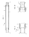
- FIG. 5 there is shown a further side view of the elongated neck 22 having an inner fitting 54 that is used to connect the elongated neck 22 to the base 12 (Fig. 1).
- Fig. 6 taken along with Fig. 5, there is an enlarged cross sectional view of that inner fitting 54 and illustrating the proximal end 34 of the elongated neck 22 where there can be seen the optical fiber 56 that transmits the light from the light source 32 (Fig. 1) to the optical fiber 56, through the elongated neck 22 to the light emanating device located in the shade assembly 26 (Fig. 1).
- the optical fiber 56 is shown located generally coaxially within the proximal inner spring 44.
- a protective sleeve 58 that encloses and contains any debris that may be created by the flexure of the proximal inner spring 44 and to prevent that debris from migrating outwardly.
- the protective sleeve 58 is, in the illustrated embodiment, a heat shrink sleeve.
- the proximal inner spring 44 can be adhesively affixed within the inner fitting 54.
- the inner fitting 54 has an inner cylindrical bore 60, within which there is located a quartz member 62 having a proximal end 64 that receives the light from the light source 32 (Fig. 1) and a distal end 66 that abuts against the proximal end of the optical fiber 56 to transmit that light to the optical fiber 56.
- the proximal end of the optical fiber 56 is bonded to the inner cylindrical bore 60, again preferably by means of an adhesive.
- the inner fitting 54 reduces in diameter towards the proximal end 34 of the elongated neck 22, thereby forming a shoulder 68, the purpose of which will be later explained.
- FIG. 7 there is shown a cross section view of an outer spring assembly 70 that is used to complete the elongated neck 22 by being located just external to and coaxial with the proximal inner spring 44 (Fig. 6).
- the outer spring assembly 70 comprises an outer spring 72 having a proximal fitting 74 and a distal fitting 76.
- Surrounding the exterior surface of the outer spring 72 is a cover sleeve 78 that provides a barrier to the migration of debris generated by the flexing of the outer spring 72 as well as to provide a good appearance to the overall device.
- the cover sleeve 78 is normally adhesively adhered to the proximal and distal fittings 74, 76 as is the outer spring 72.
- the outer spring is an extension spring that is preloaded so as to keep the elongated neck 22 in its position if there is some failure.
- the design of the outer spring 72 is dependent upon various factors, including the length of the spring, its internal stress level, the wire size, effect of corrosion, wear and the like.
- Fig. 8 taken along with Fig. 7, there is a cross sectional view of the proximal fitting 74 and, as can be seen, the proximal fitting 74 includes a cylindrical proximal end 80 and a distally extending cylindrical flange 82.
- the proximal end 80 is adapted to be plugged into the base 12 (Fig. 1) and has a pair of O-rings 84 so as to fit with a close fitting within the base 12.
- the proximal end of the outer spring 72 is affixed to the cylindrical flange 82, preferable by an adhesive and the cover sleeve 78 is also affixed to the proximal fitting 74 at an outer flange 86 and, again, preferable by means of an adhesive.
- the proximal fitting 74 there is a shoulder 88 formed that faces proximally and the purpose of which will be later explained.
- Fig. 8A taken along with Fig 7, there is a cross sectional view of the distal fitting 76 and, with this distal fitting 76, the outer spring 72 as well as the cover sleeve 78 are affixed, preferably by adhesive bonding, within an annular opening 90 formed in the distal fitting 76.
- the distal fitting 76 also has an internal opening 92 formed therein having a predetermined internal diameter and the purpose of that internal opening 92 will be later explained.
- Figs. 9 and 10 there is shown, respectively, a side view and a side cross sectional view, taken along the line 10-10 of Fig. 9, of the outer spring assembly 70 in its assembled position to make up the elongated neck 22.
- the outer spring assembly 70 has been slid over the proximal end 34 of the elongated neck 22 and is located at a position surrounding and general coaxial with the proximal inner spring 44.
- the proximal flexible section 36 has the advantage of having both the outer spring 72 and the proximal inner spring 44 acting together to prevent the distal end 24 of the elongated neck 22 (Fig. 1) from sagging downwardly and also can provide protection against that sagging even in the event of a failure either the outer spring 72 or the proximal inner spring 44.
- the outer spring assembly 70 In order to position the outer spring assembly 70 in the proper position, the outer spring assembly 70 is slid onto the proximal end 34 of the elongated neck 22 until the shoulder 88 of the outer spring assembly 70 abuts against the shoulder 68 of the inner fitting 54 so that the outer spring assembly 70 fits firmly against inner fitting 54. At that point, the internal opening 92 of the distal fitting 76 has been dimensioned to slide tighty against the outer diameter of the intermediate tubing 38. That slippage may be enhanced by the presence of some lubricious material i.e wrapped Teflon, intermediate distal fitting 76 of the outer spring assembly 70 and the outer surface of the intermediate tubing 38 as well as having a polished surface on that outer surface.
- some lubricious material i.e wrapped Teflon
- the elongated neck 22 can be directed by the user to the desired area of the infant.
- the phototherapy light device 10 can be manipulated as desired, however, with the proximal flexible section having an inner proximal spring and an outer spring proximate to each other and generally coaxial, there is a safety factor in the event of a failure of either of those springs to prevent the distal end of the light therapy device from sagging downwardly to contact the infant.
Landscapes
- Health & Medical Sciences (AREA)
- Engineering & Computer Science (AREA)
- Biomedical Technology (AREA)
- Pathology (AREA)
- Nuclear Medicine, Radiotherapy & Molecular Imaging (AREA)
- Radiology & Medical Imaging (AREA)
- Life Sciences & Earth Sciences (AREA)
- Animal Behavior & Ethology (AREA)
- General Health & Medical Sciences (AREA)
- Public Health (AREA)
- Veterinary Medicine (AREA)
- Radiation-Therapy Devices (AREA)
Applications Claiming Priority (1)
| Application Number | Priority Date | Filing Date | Title |
|---|---|---|---|
| US11/405,231 US8267922B2 (en) | 2006-04-17 | 2006-04-17 | Phototherapy light with dual spring support neck |
Publications (2)
| Publication Number | Publication Date |
|---|---|
| EP1847293A2 true EP1847293A2 (de) | 2007-10-24 |
| EP1847293A3 EP1847293A3 (de) | 2009-01-07 |
Family
ID=38265138
Family Applications (1)
| Application Number | Title | Priority Date | Filing Date |
|---|---|---|---|
| EP07106097A Withdrawn EP1847293A3 (de) | 2006-04-17 | 2007-04-13 | Phototherapieleuchte mit doppelter Nackenstützfeder |
Country Status (3)
| Country | Link |
|---|---|
| US (1) | US8267922B2 (de) |
| EP (1) | EP1847293A3 (de) |
| CA (1) | CA2584853A1 (de) |
Cited By (1)
| Publication number | Priority date | Publication date | Assignee | Title |
|---|---|---|---|---|
| EP4137202A1 (de) * | 2016-04-29 | 2023-02-22 | Neolight LLC | Phototherapievorrichtungen und -verfahren |
Families Citing this family (4)
| Publication number | Priority date | Publication date | Assignee | Title |
|---|---|---|---|---|
| WO2015041919A1 (en) | 2013-09-18 | 2015-03-26 | D-Rev: Design For The Other Ninety Percent | Phototherapy device for the treatment of hyperbilirubinemia |
| CN105664372B (zh) * | 2016-02-24 | 2018-06-19 | 广州美琳美健医疗科技有限公司 | 黄疸检测蓝光治疗仪 |
| US11058596B2 (en) | 2017-06-28 | 2021-07-13 | General Electric Company | Autoregulation of irradiance in phototherapy systems |
| CN108295381B (zh) * | 2018-04-10 | 2024-03-22 | 广州甘芸医疗科技有限公司 | 一种自动化光纤无拉扯式蓝光毯编织设备 |
Family Cites Families (31)
| Publication number | Priority date | Publication date | Assignee | Title |
|---|---|---|---|---|
| US1790500A (en) | 1931-01-27 | Charles hscher | ||
| US2607881A (en) * | 1951-04-04 | 1952-08-19 | John M Anderson | Light and mirror attachment for hospital beds |
| US2832157A (en) * | 1954-06-01 | 1958-04-29 | Perry D Hudson | Hair driers for human hair |
| US3666938A (en) * | 1971-02-17 | 1972-05-30 | Frank J Dolega | Lamp structure |
| US4698068A (en) * | 1985-09-20 | 1987-10-06 | Eric Jensen | Fire starter |
| JPH07103392B2 (ja) | 1987-06-29 | 1995-11-08 | 旭化成工業株式会社 | 電気粘性流体 |
| JPS6460903A (en) * | 1987-08-31 | 1989-03-08 | Toshiba Electric Equip | Desk lamp |
| US4809677A (en) * | 1987-09-14 | 1989-03-07 | The Boc Group, Inc. | Heater traverse mechanism for infant care center |
| US5008793A (en) * | 1990-05-07 | 1991-04-16 | Flos S.P.A. | Guidable arm, particularly for free-positioning lamps |
| US5339223A (en) * | 1993-03-24 | 1994-08-16 | Ohmeda Inc. | Servocontrol for fiberoptic phototherapy pad |
| EP0627243A1 (de) | 1993-05-24 | 1994-12-07 | Ohmeda Inc. | Laser Phototherapie |
| US5792214A (en) * | 1995-01-31 | 1998-08-11 | Medela, Inc. | Apparatus and method for treating neonatal hyperbilirubinemia |
| US5746753A (en) * | 1996-05-13 | 1998-05-05 | Boston Scientific Corporation | Needle grasping apparatus |
| US5915072A (en) * | 1997-04-30 | 1999-06-22 | Hill-Rom, Inc. | Infrared heater apparatus |
| US5851212A (en) * | 1997-06-11 | 1998-12-22 | Endius Incorporated | Surgical instrument |
| US5924681A (en) * | 1997-08-26 | 1999-07-20 | L&P Property Management Company | Preloaded spring assembly |
| US6234640B1 (en) * | 1998-05-22 | 2001-05-22 | Bruce D. Belfer | Fiber optic replicant lamp |
| US6290713B1 (en) * | 1999-08-24 | 2001-09-18 | Thomas A. Russell | Flexible illuminators for phototherapy |
| US6402681B1 (en) * | 2000-03-07 | 2002-06-11 | Hill-Rom Services, Inc. | Phototherapy apparatus |
| US6413205B1 (en) * | 2000-05-18 | 2002-07-02 | Harris County Hospital District | Infant warmer with light shield |
| US6698044B2 (en) * | 2002-03-30 | 2004-03-02 | Saul P. Greenfield | Pediatric stirrup device and method |
| US7147653B2 (en) * | 2002-08-23 | 2006-12-12 | Lumitex, Inc. | Pad like device for use during phototherapy treatment |
| WO2004106795A1 (ja) | 2003-05-30 | 2004-12-09 | Kokusan Rasenkan Co., Ltd. | フレキシブルパイプ及びその製造方法 |
| BR8302354U (pt) * | 2003-09-17 | 2004-05-18 | Orlando Rossi Jr | Aperfeiçoamento introduzido em fonte de luz fototerápica para tratamento da hiperbilirrubinemia |
| US7357811B2 (en) * | 2003-10-22 | 2008-04-15 | General Electric Company | Integrated procedure light for infant care apparatus |
| US20060072327A1 (en) * | 2004-09-30 | 2006-04-06 | Adesso Inc. | Gooseneck lighting apparatus with decorative jelly sleeve |
| US20060077672A1 (en) * | 2004-09-30 | 2006-04-13 | Adesso Inc. | Gooseneck lighting apparatus with decorative woven sleeve |
| US20060098961A1 (en) * | 2004-11-08 | 2006-05-11 | Jess Seutter | Baby warmer |
| US8109981B2 (en) * | 2005-01-25 | 2012-02-07 | Valam Corporation | Optical therapies and devices |
| US7290898B2 (en) * | 2005-03-31 | 2007-11-06 | Biz Research Inc. | Portable and mobile illumination and detection |
| US20060278816A1 (en) * | 2005-06-09 | 2006-12-14 | Booty Donald J | Portable mountable indoor lamp having a positionable lamp head and motion and light sensors which can be aimed |
-
2006
- 2006-04-17 US US11/405,231 patent/US8267922B2/en not_active Expired - Fee Related
-
2007
- 2007-04-12 CA CA002584853A patent/CA2584853A1/en not_active Abandoned
- 2007-04-13 EP EP07106097A patent/EP1847293A3/de not_active Withdrawn
Cited By (2)
| Publication number | Priority date | Publication date | Assignee | Title |
|---|---|---|---|---|
| EP4137202A1 (de) * | 2016-04-29 | 2023-02-22 | Neolight LLC | Phototherapievorrichtungen und -verfahren |
| US12226652B2 (en) | 2016-04-29 | 2025-02-18 | NeoLight LLC | Phototherapy apparatuses and methods |
Also Published As
| Publication number | Publication date |
|---|---|
| US8267922B2 (en) | 2012-09-18 |
| EP1847293A3 (de) | 2009-01-07 |
| CA2584853A1 (en) | 2007-10-17 |
| US20070244525A1 (en) | 2007-10-18 |
Similar Documents
| Publication | Publication Date | Title |
|---|---|---|
| EP1847293A2 (de) | Phototherapieleuchte mit doppelter Nackenstützfeder | |
| US5497295A (en) | Lighting system | |
| US5029581A (en) | Laser therapeutic apparatus | |
| US4842356A (en) | Light ray radiation device for use in medical treatment of the nose and throat passages | |
| US6187030B1 (en) | Photodynamic therapy method | |
| JP5238077B2 (ja) | Uv光線治療提供装置 | |
| TW200840539A (en) | Thermally robust illumination probe tip | |
| CA2139820C (en) | Fiberoptic illuminator for infant care | |
| US2896066A (en) | Lighting apparatus for dental surgeries | |
| US20060195165A1 (en) | Optical therapy devices, systems, kits and methods for providing therapy to a body cavity | |
| CN101808565A (zh) | 柔性红外输送装置和方法 | |
| JPH0351194B2 (de) | ||
| JP2003038663A (ja) | レーザ治療装置 | |
| CN105920741A (zh) | 一种氦氖激光复合led治疗仪 | |
| KR20210001284A (ko) | 비염치료기 | |
| US4790500A (en) | Optical conductor cable supporting stand for a light ray radiation device used in medical treatment | |
| IE904554A1 (en) | Infrared delivery system with aiming component | |
| US1656777A (en) | Combination heat and light therapy lamp | |
| EP1813307A1 (de) | Phototherapieleuchte mit Stufenlinse für eine Säuglingspflegevorrichtung | |
| US4785811A (en) | Solar ray energy radiation device for use in medical treatment | |
| US6115540A (en) | Radiative keyboard heating apparatus | |
| US4911511A (en) | Light ray radiation stand | |
| US4995712A (en) | Light radiation stand | |
| AU598223B2 (en) | A solar ray energy radiation device for use in medical treatment | |
| CN205360265U (zh) | 蓝光治疗仪 |
Legal Events
| Date | Code | Title | Description |
|---|---|---|---|
| PUAI | Public reference made under article 153(3) epc to a published international application that has entered the european phase |
Free format text: ORIGINAL CODE: 0009012 |
|
| AK | Designated contracting states |
Kind code of ref document: A2 Designated state(s): AT BE BG CH CY CZ DE DK EE ES FI FR GB GR HU IE IS IT LI LT LU LV MC MT NL PL PT RO SE SI SK TR |
|
| AX | Request for extension of the european patent |
Extension state: AL BA HR MK YU |
|
| PUAL | Search report despatched |
Free format text: ORIGINAL CODE: 0009013 |
|
| AK | Designated contracting states |
Kind code of ref document: A3 Designated state(s): AT BE BG CH CY CZ DE DK EE ES FI FR GB GR HU IE IS IT LI LT LU LV MC MT NL PL PT RO SE SI SK TR |
|
| AX | Request for extension of the european patent |
Extension state: AL BA HR MK RS |
|
| RIC1 | Information provided on ipc code assigned before grant |
Ipc: F21V 21/32 20060101ALI20081128BHEP Ipc: A61N 5/06 20060101AFI20070725BHEP |
|
| 17P | Request for examination filed |
Effective date: 20090707 |
|
| 17Q | First examination report despatched |
Effective date: 20090731 |
|
| AKX | Designation fees paid |
Designated state(s): DE FR GB |
|
| GRAP | Despatch of communication of intention to grant a patent |
Free format text: ORIGINAL CODE: EPIDOSNIGR1 |
|
| INTG | Intention to grant announced |
Effective date: 20160408 |
|
| STAA | Information on the status of an ep patent application or granted ep patent |
Free format text: STATUS: THE APPLICATION IS DEEMED TO BE WITHDRAWN |
|
| 18D | Application deemed to be withdrawn |
Effective date: 20160819 |